

AIR CONDITIONER CONTENTS
SYSTEM AIR CONDITIONER
1. Precautions
2. Product Specifications
3. Disassembly and Reassembly
4. Troubleshooting
5. PCB Diagram
6. Reference Sheet
Indoor Unit Outdoor Unit
Model : AC036JB1DEC AC036JCADEC
AC052JB1DEC AC052JCADEC
AC071JB1DEC AC071JCADEC
AC026MN1DKH
AC035MN1DKH
Model Code : AC036JB1DEC/TL AC036JCADEC/TL
AC052JB1DEC/TL AC052JCADEC/TL
AC071JB1DEC/TL AC071JCADEC/TL
AC026MN1DKH/TK
AC035MN1DKH/TK
AC026MN1DKH/EU
AC035MN1DKH/EU
AC036JB1DEC/TL
AC026MN1DKH/TK
AC035MN1DKH/TK
AC026MN1DKH/EU
AC035MN1DKH/EU
AC036JCADEC/TL
AC052JCADEC/TL
AC052JB1DEC/TL
AC071JB1DEC/TL
AC071JCADEC/TL

Contents
11. Precautions
........................................................................................................................................
1-1
1-1 Precautions for the Service
..............................................................................................................
1-1
1-2 Precautions related to static electricity and PL
............................................................................
1-1
1-3 Precautions related to product safety
...........................................................................................
1-2
1-4 Other precautions
..............................................................................................................................
1-2
12. Product Specifications
...............................................................................................................
2-1
2-1 The Feature of Product
.....................................................................................................................
2-1
2-2 Product Specifications
......................................................................................................................
2-2
2-3 Accessories
..........................................................................................................................................
2-3
13. Disassembly and Reassembly
...............................................................................................
3-1
3-1 Indoor Unit
.........................................................................................................................................
3-2
3-2 Outdoor Unit
.....................................................................................................................................
3-15
14. Troubleshooting
............................................................................................................................
4-1
4-1 Setting an indoor unit address and installation option
............................................................
4-1
4-1-1 The procedure of setting option
..........................................................................................
4-1
4-1-2 The procedure of setting option
..........................................................................................
4-2
4-1-3 Order for Setting Options
......................................................................................................
4-5
4-1-4 Setting an indoor unit installation option
..........................................................................
4-6
4-1-5 Changing a particular option
................................................................................................
4-8
4-1-6 Option code for each model
................................................................................................
4-9
4-2 Items to check before diagnostics
.................................................................................................
4-10
4-2-1 Test run mode and View mode
............................................................................................
4-10
4-2-2 Troubleshooting for indoor unit
.........................................................................................
4-11
4-2-3 Changing a particular option ............................................................................................................. 4-14
4-2-4 Option code for each model
................................................................................................
4-15
4-3 Items to check before diagnostics
..................................................................................................
4-16
4-3-1 Four directions cassette type
...............................................................................................
4-16
4-3-2 Indoor heat exchanger temperature sensor (open/short)
.............................................
4-19
4-3-3 ECO mode(Power save)
..........................................................................................................
4-19
4-3-4 Communication error after finishing Tracking
.................................................................
4-21
4-3-5 Troubleshooting for outdoor unit
.......................................................................................
4-22
4-3-6 Wired remote controller
.......................................................................................................
4-24

4-4 Troubleshooting by symptoms .................................................................................................................... 4-27
4-4-1 Indoor temperature sensor (open/short)(E121).......................................................................... 4-27
4-4-2 Indoor heat exchanger temperature sensor (open/short) (E122) ....................................... 4-28
4-4-3 Indoor FAN error (E154) ....................................................................................................................... 4-29
4-4-4 Communication error after finishing Tracking (E202) .............................................................. 4-30
4-4-5 Indoor unit float sensor error (E153) ................................................................................................ 4-31
4-4-6 EEPROM circuit failure (E162) ............................................................................................................. 4-32
4-4-7 Thermal Fuse Open Error ...................................................................................................................... 4-33
1
5. PCB Diagram and Parts List
.......................................................................................................
5-1
5-1 Indoor Unit
.........................................................................................................................................
5-1
5-1-1 Indoor Unit
..............................................................................................................................
5-1
5-1-2 Panel PCB
.................................................................................................................................
5-2
5-2 Outdoor Unit
.....................................................................................................................................
5-6
6. Reference Sheet
.................................................................................................................................
6-1
6-1 Index for Model Name
......................................................................................................................
6-1
6-2 Refrigerating Cycle Diagramc
..........................................................................................................
6-4

Samsung Electronics 1-1
1. Precautions
1-1 Precautions for the Service
●Use the standard parts when replacing the electric parts.
– Confirm the model name, rated voltage, rated current of the electric parts.
●When repairing the equipment, connection of the harness parts must be firm and solid.
– A loose connection may cause noise or other malfunction.
●When assembling and disassembling the equipment while it is laid down, lay it on soft cloth.
– Otherwise it may scratch the back of the exterior of the product.
●Remove dust or dirt completely from the housing block, wiring block and service parts during repair.
– This helps prevent the danger of fire caused by tracking or short circuit.
●Fasten the valve caps of service valves and charging valves of outdoor unit as much as possible using adjustable wrenches.
●Check the status of the components’ assembly after repair service.
– The status must be the same as before the repair service.
1-2 Precautions related to static electricity and PL
● The PCB power supply block is susceptible to static electricity. Therefore, care must be taken during repair or measuring
while the power is on.
– Wear insulation gloves for PCB repair or measuring.
● Check whether the installation location is at least two meters away from other electronic products such as TV, video, or
audio.
– Otherwise, the video quality might be degraded or noise might be generated.
●Do not let end users repair the products themselves.
– Unauthorized disassembly might cause electric shock or fire.

1-2 Samsung Electronics
1-3 Precautions related to product safety
●Do not pull the power cord and do not touch the power plug or aux power switch with wet hands.
– It might cause electric shock or fire.
●A damaged power line or power plug must be replaced to prevent danger.
●Do not bend the power cable with excessive force, and do not place a heavy weight on the case as it might damage the cable.
– It might cause electric shock or fire.
●Do not use multiple electric outlets.
– This might cause electric shock or fire.
●Connect the ground terminal when necessary.
– You must connect the ground terminal if you determine that there is a danger of electric leakage due to moisture or water.
●Unplug the power cable or turn off the auxiliary power switch for electric part replacement and repair service.
– Otherwise it might cause electric shock.
●Instruct end users to separate the batteries from the remote controllers and store them separately when the product is not
used for long time.
– Otherwise leakage from the dry cell may cause problems with the remote controller.
1-4 Other precautions
●The pipes should have no leaks during installation, and the compressor must be stopped before removing connecting pipes
for pump down work. Operating the compressor while the service valve is open and coolant pipe is not properly connected
may cause explosion or injury due to abnormal high pressure created inside the coolant cycle as the air can be absorbed
through the pipe.
●Pump Down work procedure (When uninstalling the product)
– Turn on the air conditioner, select cooling operation, and run the compressor for more than three minutes.
– Release the high pressure and low pressure valve caps.
– Close the high pressure valve completely using an L-wrench
– After about two minutes, close the low pressure valve completely.
– Stop running the air conditioner.
– Separate the connecting pipe.

Samsung Electronics 2-1
●Built-in Cassette Type
After installed, the air conditioner can be harmonized with a room interior.
●High Performance & Energy Saving
With the advanced BLDC inverter technology, it makes a room cool with highly energy saving and arises the efficiency of air conditioner.
●Long Ambient Operation(In Low Temperature)
It can arise the reliability and the capacity of the air conditioner, especially operated in low temperature.
●Eco-friendly Product(Lead-Free, RoHS, WEEE)
●Easy installation of ultra-lightweight indoor unit
2. Product Specifications
2-1 The Feature of Product
2-2 Samsung Electronics
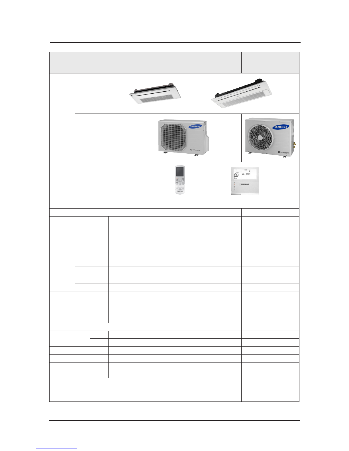
2-2 Product Specifications
ITEM
AC036JB1DEC/TL
AC026/035MN1DKH/TK
AC026/035MN1DKH/EU
AC036JCADEC/TL
AC052JB1DEC/TL
AC052JCADEC/TL
AC071JB1DEC/TL
AC071JCADEC/TL
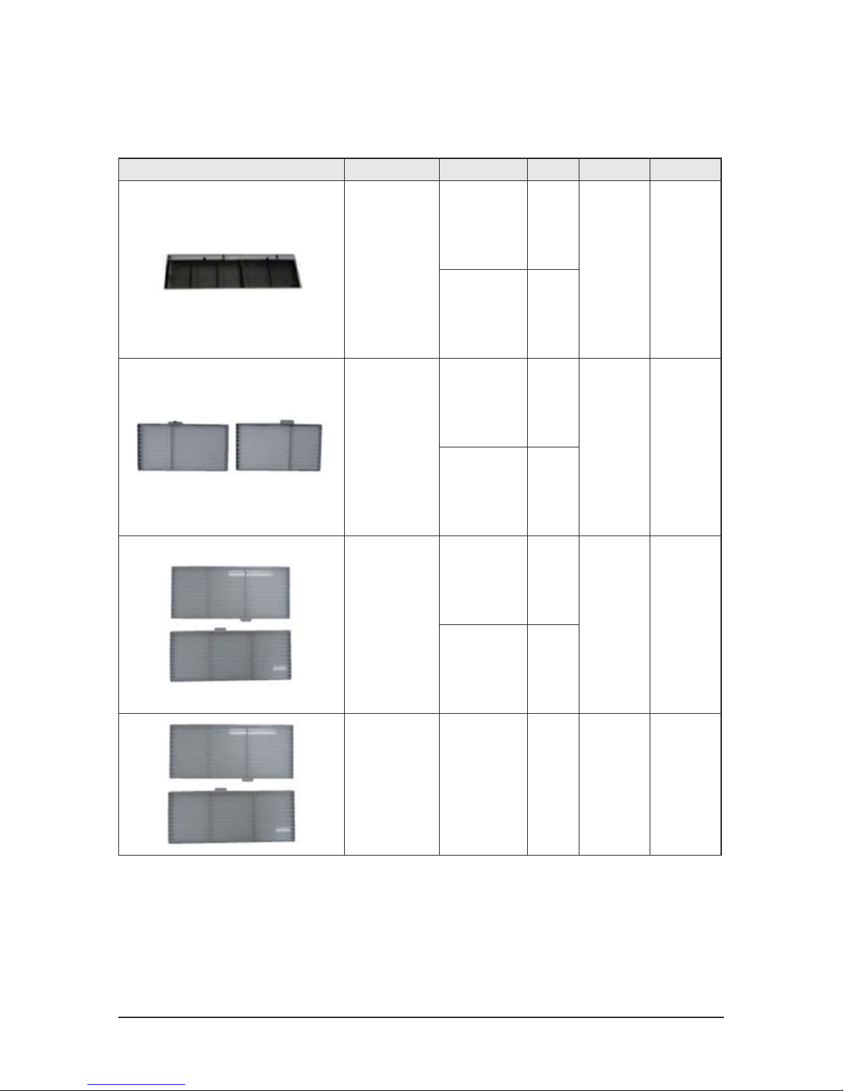
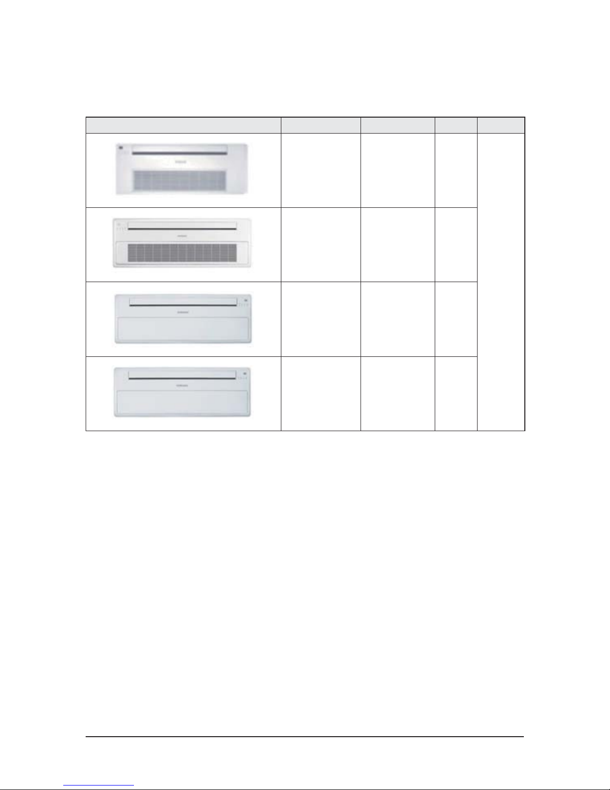
IMAGE
Indoor Unit
Outdoor Unit
Remote Controller
Wireless remote controller
: MR-EC00
Wired remo te controller
: MWR-WE10
Power Product 1Φ, 230V/50Hz 1Φ, 230V/50Hz 1Φ, 230V/50Hz
Indoor L x H x D mm 970x135x410 1200x138x450 1200x138x450
Panel L x H x D mm
1180x25x460(PC1NUSMAN)
1198x25x500(PC1NUPMAN)
1410 x 23 x 500 1410 x 23 x 500
Outdoor L x H x D mm 790x548x285 790x548x285 880x638x310
Indoor Product kg(Net) 9.5 13.4 13.4
Outdoor Product kg(Net) 34.0 34.0 46.1
Capacity
Cooling(STD) W 3,600 5,200 7,100
Heating(STD) W - - -
Power
Consumption
Cooling(STD) W 1,200 1,730 2,730
Heating(STD) W - - -
Operation
current
Cooling(STD) A 5.5 7.8 11.5
Heating(STD) A - - -
Noise
Indoor unit (C/H) dB 35/- 39/- 41/-
Outdoor unit (C/H) dB 49/- 50/- 50/-
Refrigerant 900 900 1,000
Connecting Pipe
Liquid mm 6.35 6.35 6.35
Gas mm 12.7 12.7 15.88
Additional Refrigerant (R410A) g/m 20 20 20
Standard m 5 5 5
Extension length(Total) m 30 30 30
Extension length(Elevation) m 15 15 15
Option Code
Product Option 01707C-11042D-272800-375260 01807C-19042C-273400-372560 01807C-19044C-274800-37F560
Installation option 020000-100000-200000 -300000 020000-100000-200000-300000 020000-100000-200000-300000
Cycle Option 034000-103100-200000-300020 034C00-104000-200000-300020 034C00-103C00-200000-300020
Samsung Electronics 2-3
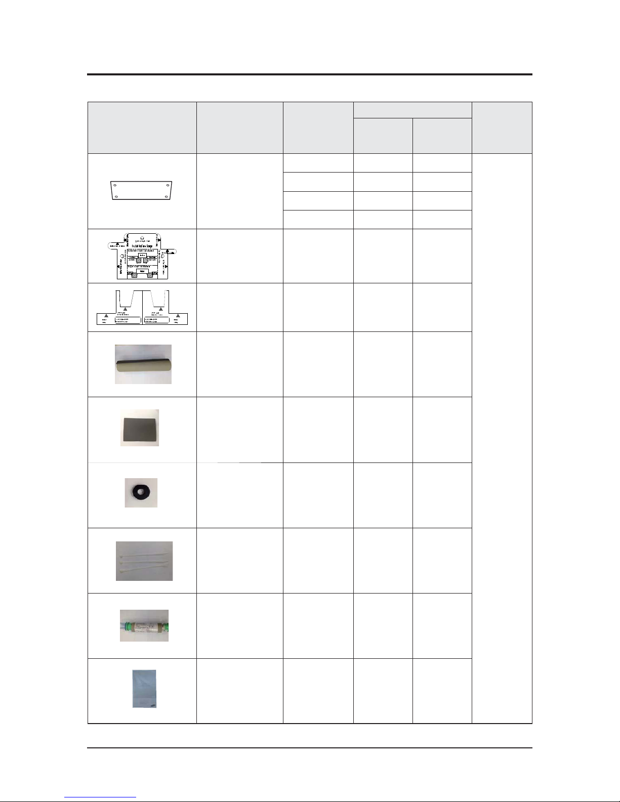
2-3 Accessories
■1WAY CASSETTE (AC✳✳✳JB1DEC Series)
Item Descriptions Code-No.
Q'TY
Remark
AC036JB1DEC
AC052JB1DEC
AC071JB1DEC
Pattern sheet
DB69-01947A 1 1
Essential Offer
(Indoor Unit)
DB69-01947B 1 1
DB69-03017A 1 1
DB69-03017B 1 1
Installation gauge DB69-01936A 1 1
Installation gauge DB69-03011A 1 1
Seal-drain ass'y DB62-05810A 1 1
Insulation-base DB72-00401C 2 2
Grommet hanger DB63-00237A 8 8
Cable tie DB65-10088C 3 3
Ass'y drain hose joint DB94-01258C 1 1
User & Installation
manual
DB68-05546A 1 1
2-4 Samsung Electronics
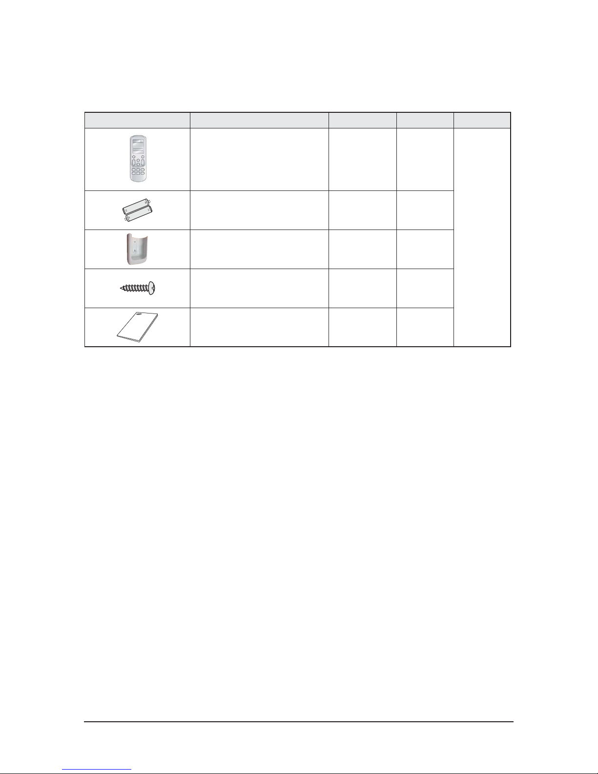
■Wireless remote controller (MR-EC00)
Item Descriptions Code-No. Q'TY Remark
Wireless remote controller DB93-14643K 1
Optional
Batteries for remote controller
(specification: ""AAA"" type)
4301-000121 2
Remote controller holder DB61-06087A 1
M4×16 screw 6002-000581 2
User’s manual DB68-04667A 1
Samsung Electronics 2-5
■Wired remote controller (MWR-WE10) [Code No. : DB97-17002B]
Item Descriptions Code-No. Q'TY Remark
Wired remote controller DB93-11251B 1
Optional
Cable tie DB65-10088B 2
Cable clamp DB65-10074E 3
M4×16 Screw 6002-000474 5
User’s manual DB98-32810A 1
Installation guide DB98-32811A 1
2-6 Samsung Electronics
䒲 Central controller (MCM-A202D) [Code No. : DB97-18602B]
Item Descriptions Code-No. Q'TY Remark
Central controller DB93-03425N 1
Optional
Cable tie DB65-10088B 2
Cable clamp DB65-10074E 5
M4 X 16 Screw 6002-000474 7
User’s manual DB98-33437A 1
Installation guide DB98-33434A 1
Samsung Electronics 2-7
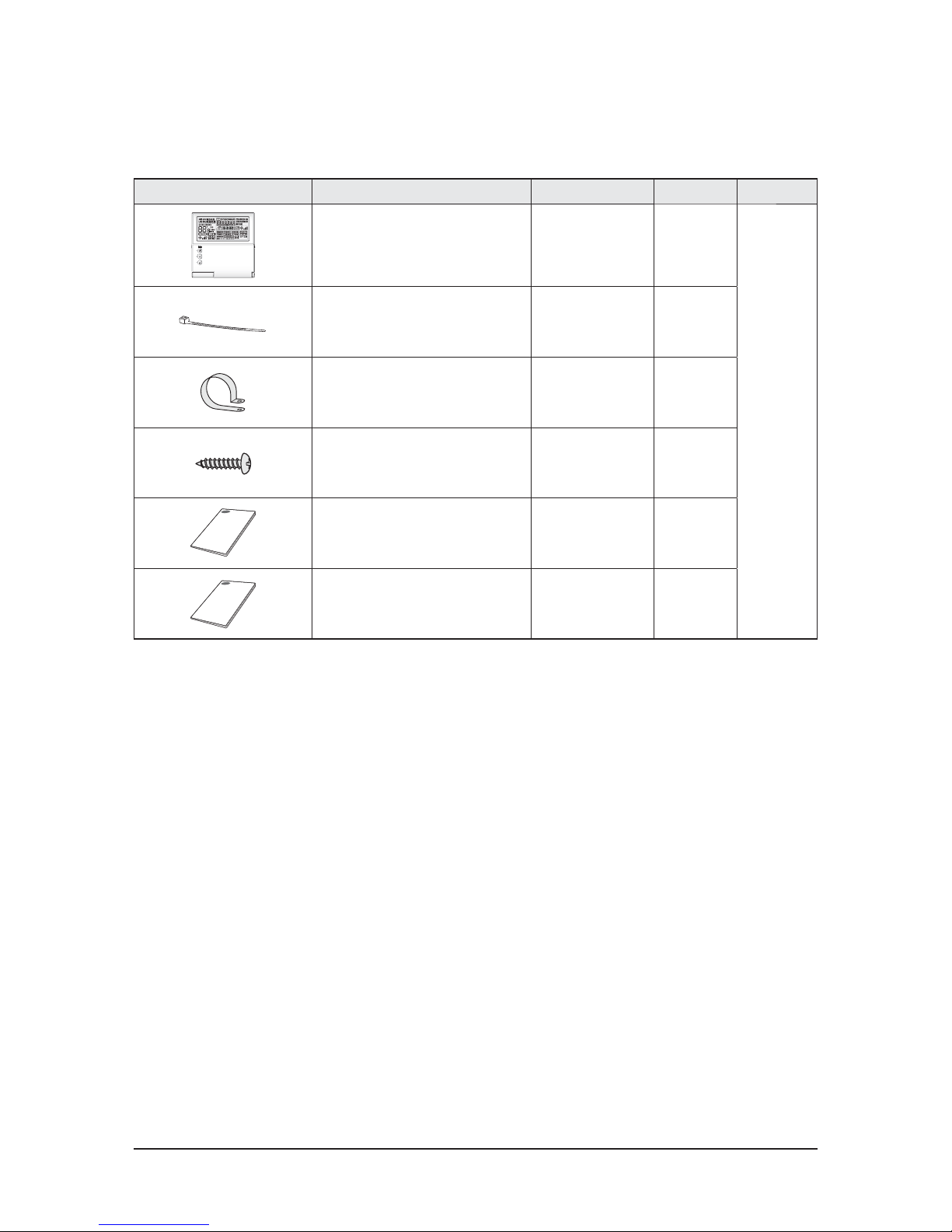
䒲 Filter accessory
Item Descriptions Code-No. Q'TY Panel Code Remark
Dust filter
DB63-01694A 1
PC1NUSMAN
Basic/
Water wash
DB63-01695A 1
Dust filter
DB63-02354A 1
PC1NUPMAN
Basic/
Water wash
DB63-02355A 1
Dust filter
DB63-02276A 1
PC1BWSEAN
Basic/
Water wash
DB63-02277A 1
Dust filter DB63-02277A 2 PC1BWPEAN
Basic/
Water wash
2-8 Samsung Electronics
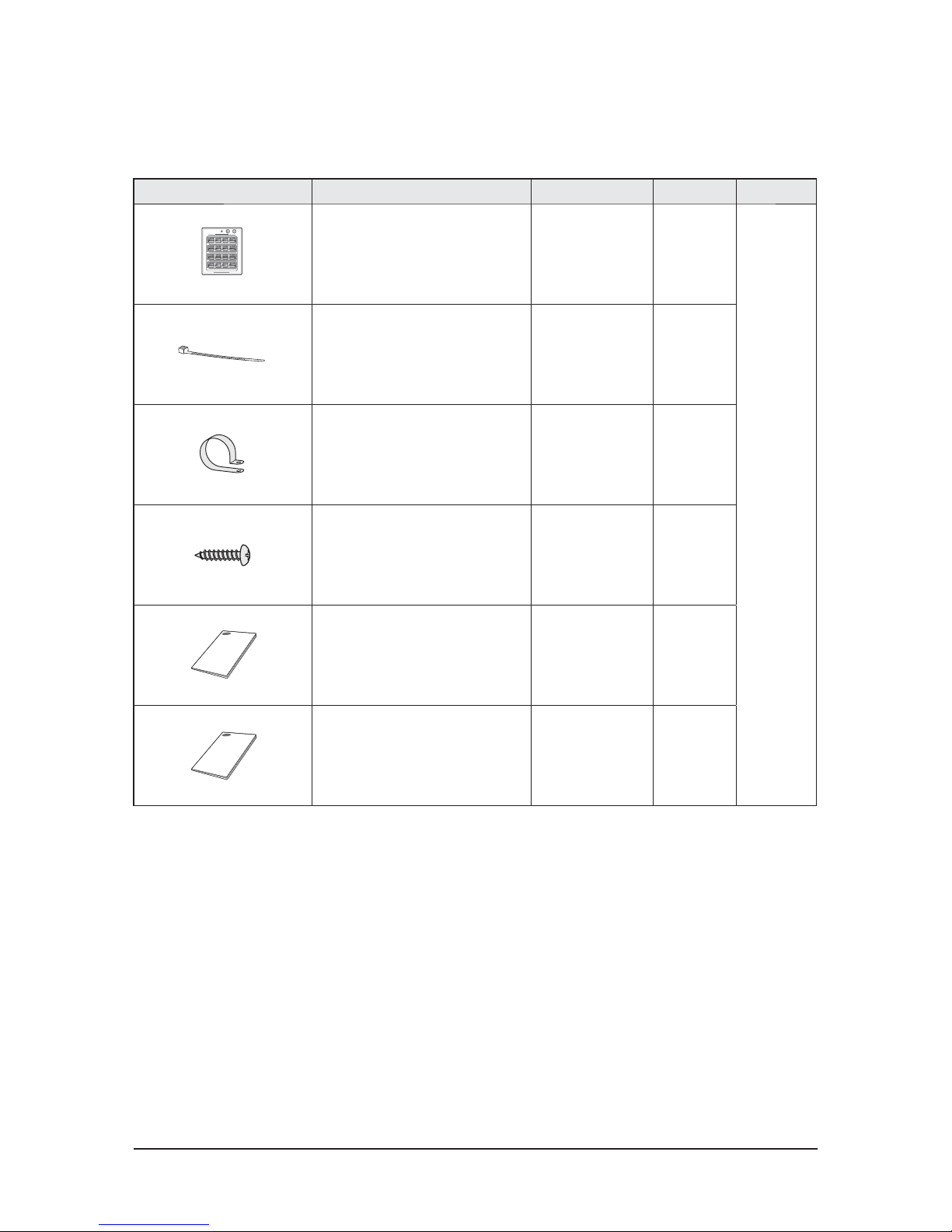
䒲 Front panel
Item Descriptions Code-No. Q'TY Remark
PC1NUSMAN AC036JB1DEC* 1
PC1BWSEAN
AC052JB1DEC*
AC071JB1DEC*
2
PC1NUPMAN AC036JB1DEC* 5
PC1BWPEAN
AC052JB1DEC*
AC071JB1DEC*
7
Samsung Electronics 3-1
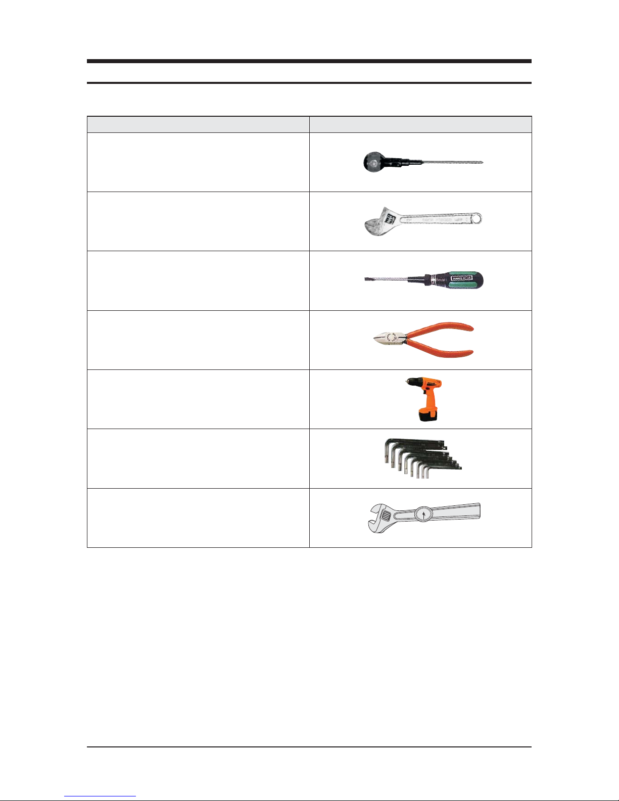
QNecessary Tools
3. Disassembly and Reassembly
Item Remarks
+Screw Driver
Monkey Spanner
–Screw Driver
Nipper
Electric Motion Driver
L-Wrench
Spanner Torque Wrench
3-2 Samsung Electronics
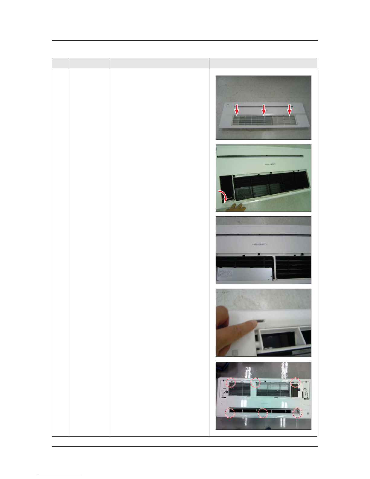
No Parts Procedure Remark
1 PANEL & FILTER
NORMAL TYPE
(PC1NWSK 1N
PC1NWAK 1N)
1)
Push the push button of grille and open it.
2)
Detach one clip from panel and separate the
grille from panel tilting the grille 45°.
3)
Detach filter from panel.
4)
Detach 3 cover screws.
5)
Unscrew 6 panel fixing screws from indoor
unit.(use +screw driver)
3-1 Indoor unit
䒲 1WAY CASSETTE (AC036JB1DEC Series)
Samsung Electronics 3-3
No Parts Procedure Remark
6)
Press the left and right hook of panel and
detach the panel from the indoor unit.

3-4 Samsung Electronics
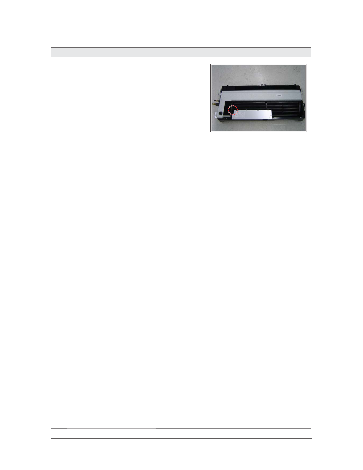
No Parts Procedure Remark
2 Control-Box
1)
Unscrew 5 fixing screws of drain pan.
(use +screw driver)
2)
Pull the drain pan and detach it from indoor
unit.
Be careful that your hands don't touch heat
exchanger panel when you detach the drain
pan.
3 ELECTRICAL
EQUIPMENT PART
1)
Unscrew 5 fixing screws of electrical
equipment part and detach the cover.
(use +screw driver)
Samsung Electronics 3-5
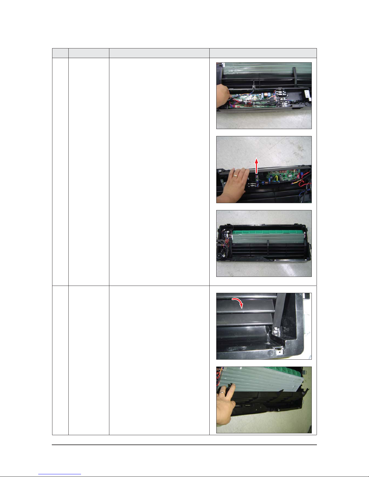
No Parts Procedure Remark
ELECTRICAL
EQUIPMENT PART
2)
Detach several connector connected to the
indoor unit PCB.
3)
Detach electrical equipment part from indoor
unit.
4 DRAIN SUB
1)
Press the hook of drain sub and detach it.
3-6 Samsung Electronics
No Parts Procedure Remark
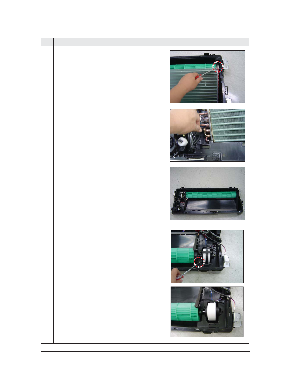
5 HEAT EXCHANGER
1)
Unscrew 1 fixing screws of heat exchanger.
(use +screw driver)
2)
Detach indoor unit sensor from heat
exchanger.
3) Detach heat exchanger from indoor unit.
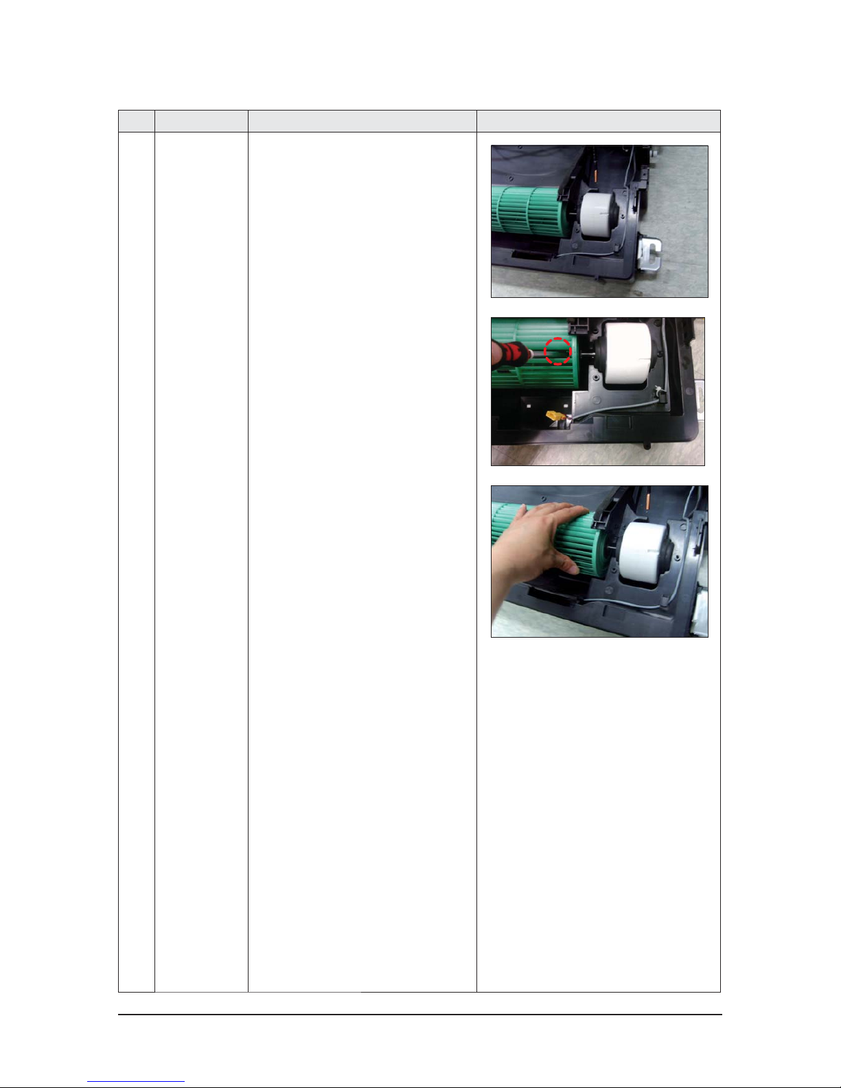
6 CROSS PAN
1)
Unscrew 3 fixing screws of cover fan motor.
(use +screw driver)
2) Detach cover fan motor from indoor unit.
Samsung Electronics 3-7
No Parts Procedure Remark
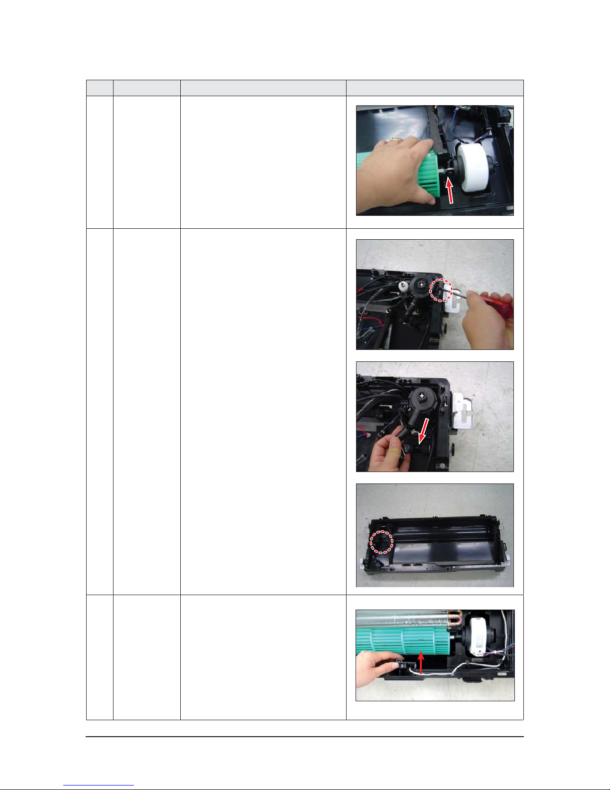
6 CROSS PAN
3)
Detach cross fan from indoor unit.
7 DRAIN PUMP
1) Unscrew 1 fixing screws of cover drain pump.
(use +screw driver)
2) Detach drain hose from drain pump.
3) Detach drain pump from indoor unit.
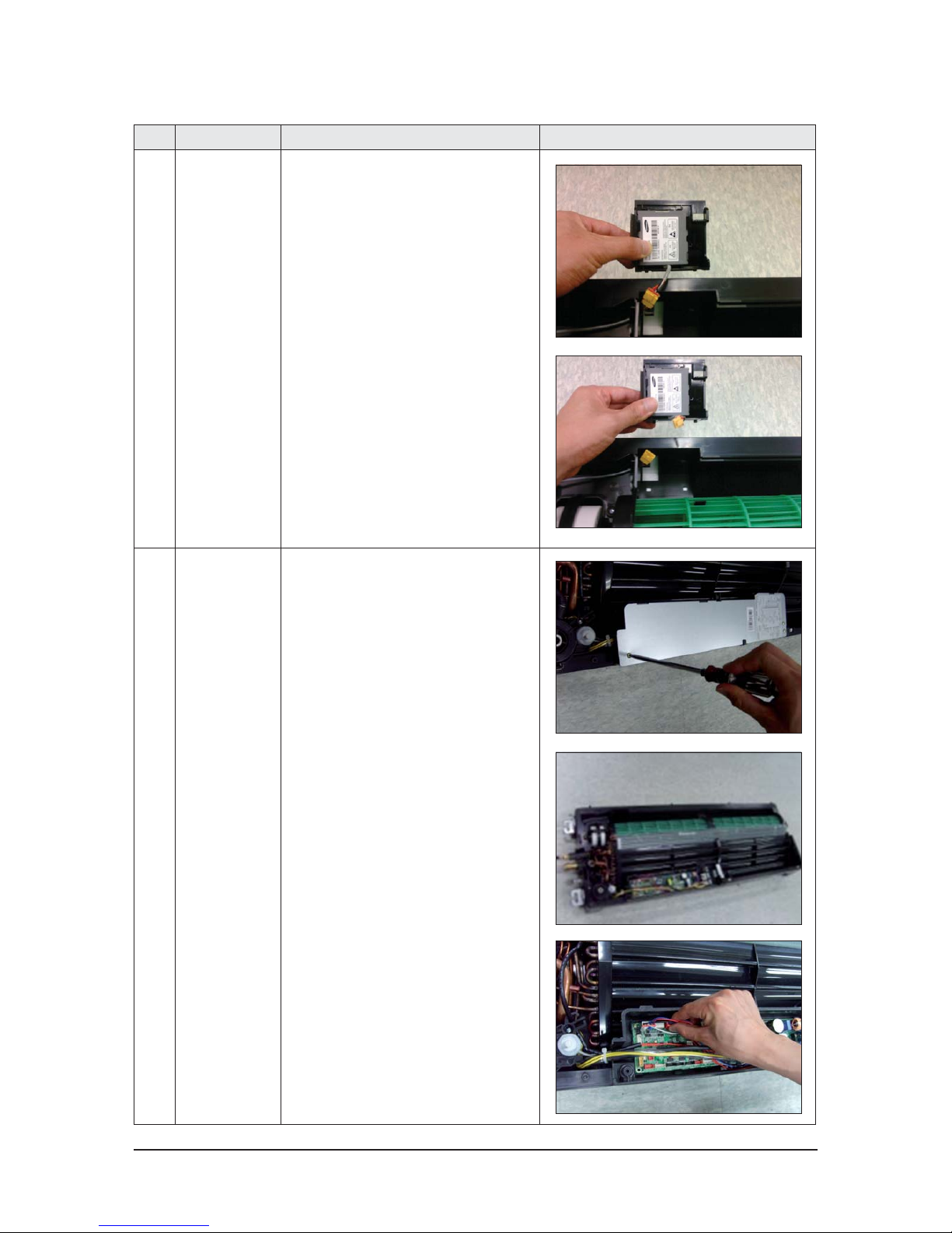
8 SPI KIT 1) Detach SPI KIT from.
3-8 Samsung Electronics
No Parts Procedure Remark
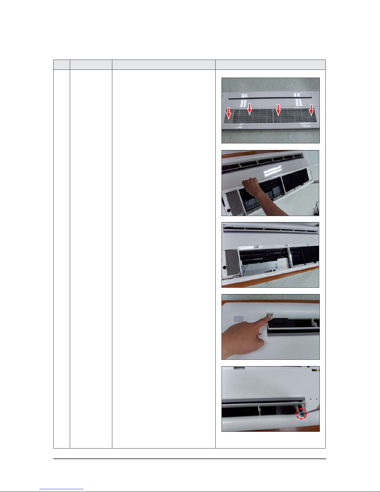
1 PANEL & FILTER
NORMAL
TYPE(PC1NWSK 1N
PC1NWAK 1N)
1) Push the push button of grille and open it.
2) Detach one clip from panel and separate the
grille from panel tilting the grille 90°.
3) Detach filter from panel.
4) Detach 4 cover screws.
5) Unscrew 7 panel fixing screws from indoor
unit.(use +screw driver)
䒲 1WAY CASSETTE (AC052/71JB1DEC Series)
Samsung Electronics 3-9
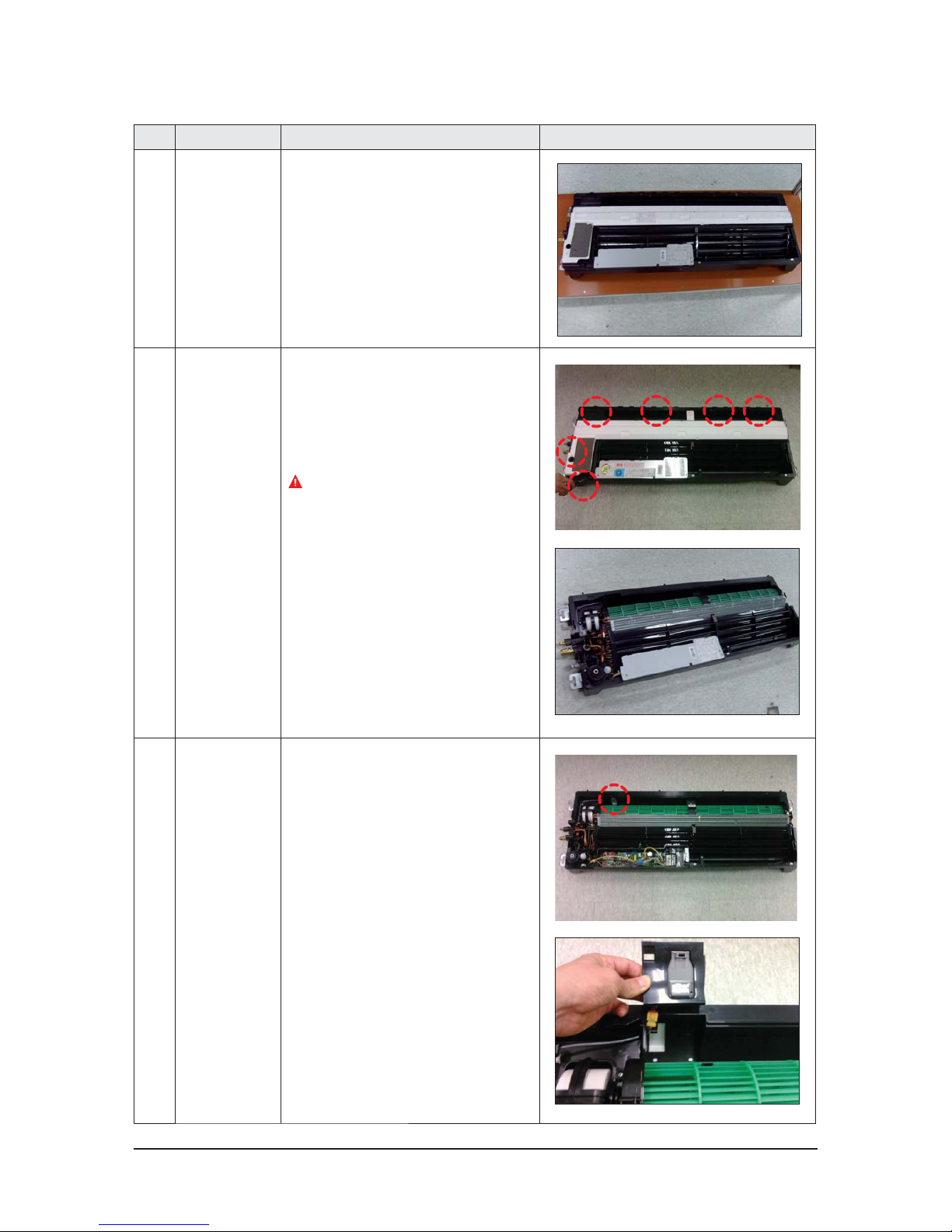
No Parts Procedure Remark
6) Press the left and right hook of panel and
detach the panel from the indoor unit.
2 DRAIN PAN 1) Unscrew 6 fixing screws of drain pan.
(use +screw driver)
2) Detach from indoor unit after separating
2 drain pan fixing hook
Be careful that your hands don't touch heat
exchanger panel when you detach the drain
pan.
3 SPI-KIT(option) 1) Detach SPI KIT from indoor unit as as shown
in the figure.
3-10 Samsung Electronics
No Parts Procedure Remark
4 ELECTRICAL
EQUIPMENT PART
1) Detach a cover unscrewing 3 electrical
equipment part fixing screw.
2) Detach several connector connected to
indoor unit PCB.
Samsung Electronics 3-11
No Parts Procedure Remark
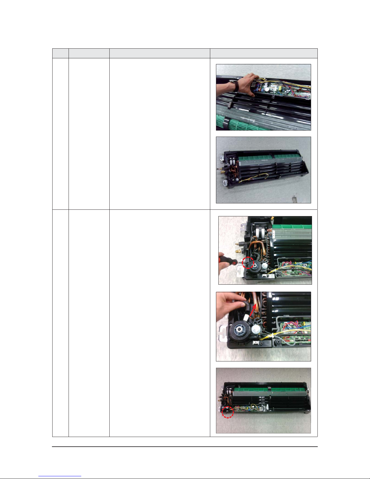
ELECTRICAL
EQUIPMENT PART
3) Detach electrical equipment part from
indoor unit.
5 DRAIN PAN 1) Unscrew 2 fixing screws of drain pan.
(use +screw driver)
2) Release band ring and Detach drain hose
from drain pump.
3) Detach drain pump from indoor unit.
3-12 Samsung Electronics
No Parts Procedure Remark
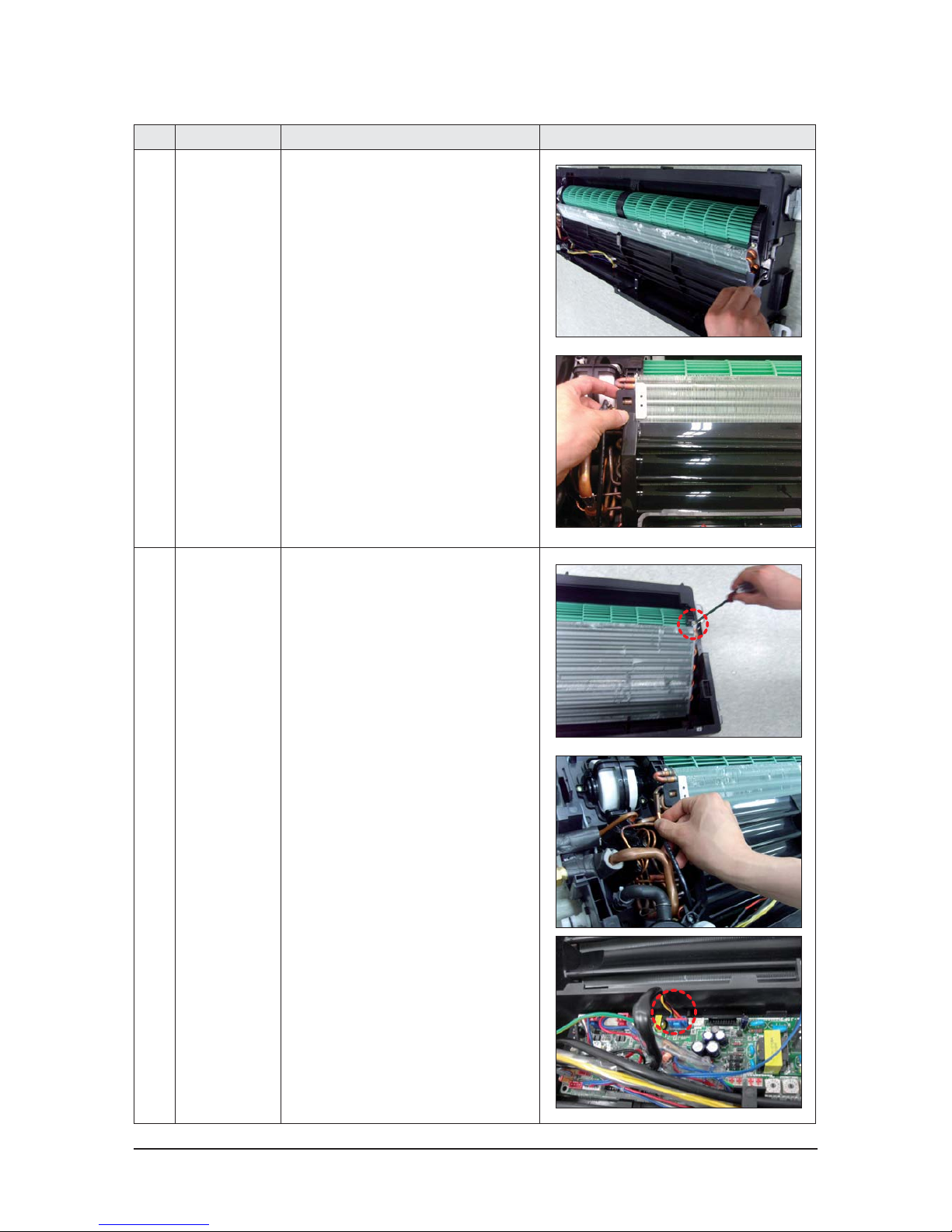
6 DRAIN SUB
1) Unscrew a drain sub fixing screw.
(use +screw driver)
2) Hold hook of drain sub and detach it.
7 HEAT EXCHANGER 1) Unscrew 1 fixing screws of heat exchanger.
(use +screw driver)
2) Detach indoor unit sensor from heat
exchanger.
3) Detach EEV connector from PCB.
Samsung Electronics 3-13
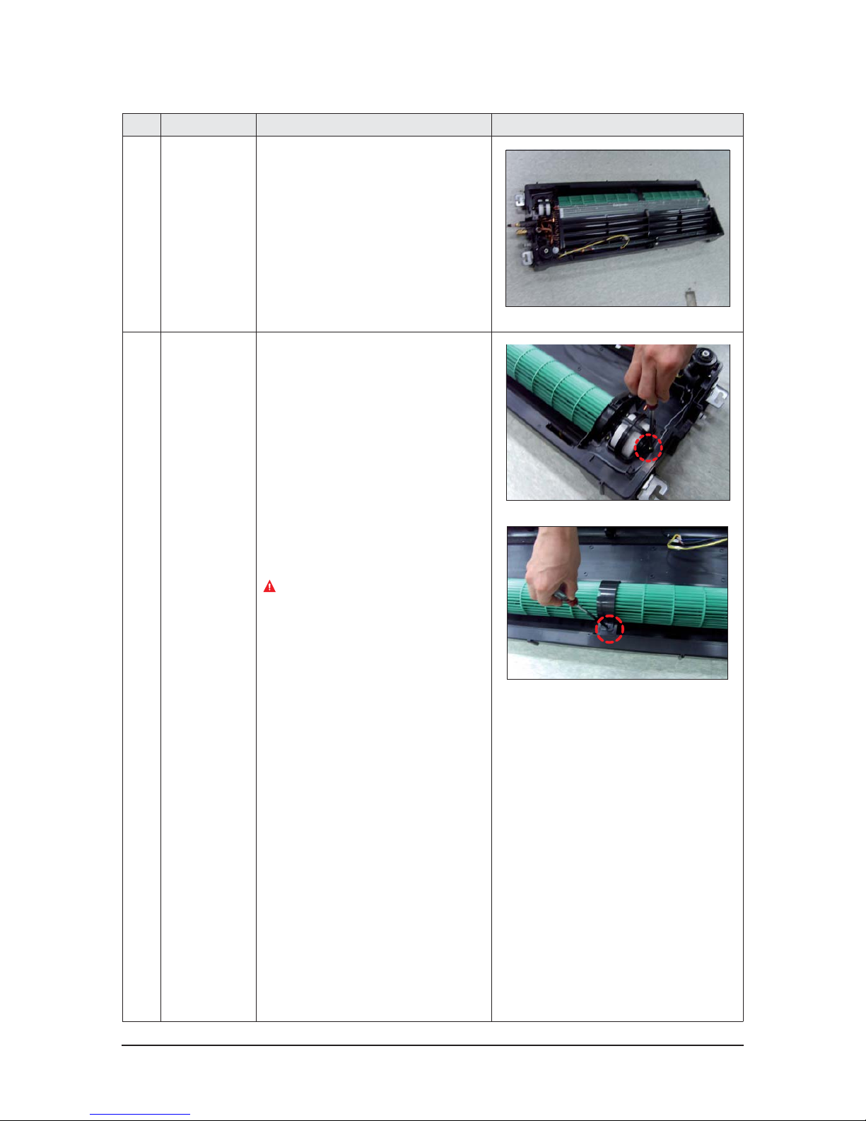
No Parts Procedure Remark
4) Detach heat exchanger from indoor unit.
8 CROSS PAN 1) Unscrew 3 fixing screws of cover fan motor.
(use +screw driver)
2) Unscrew a fixing screw of holder fan.
(use +screw driver)
Assemble to match a side end of holder fan
with a side of cross fan when you
reassemble it.
3-14 Samsung Electronics
No Parts Procedure Remark
3) Detach cover fan motor from indoor unit.
4) Unscrew 1 fixing screws of cross fan.
5) Detach cross fan from indoor unit.
Samsung Electronics 3-15
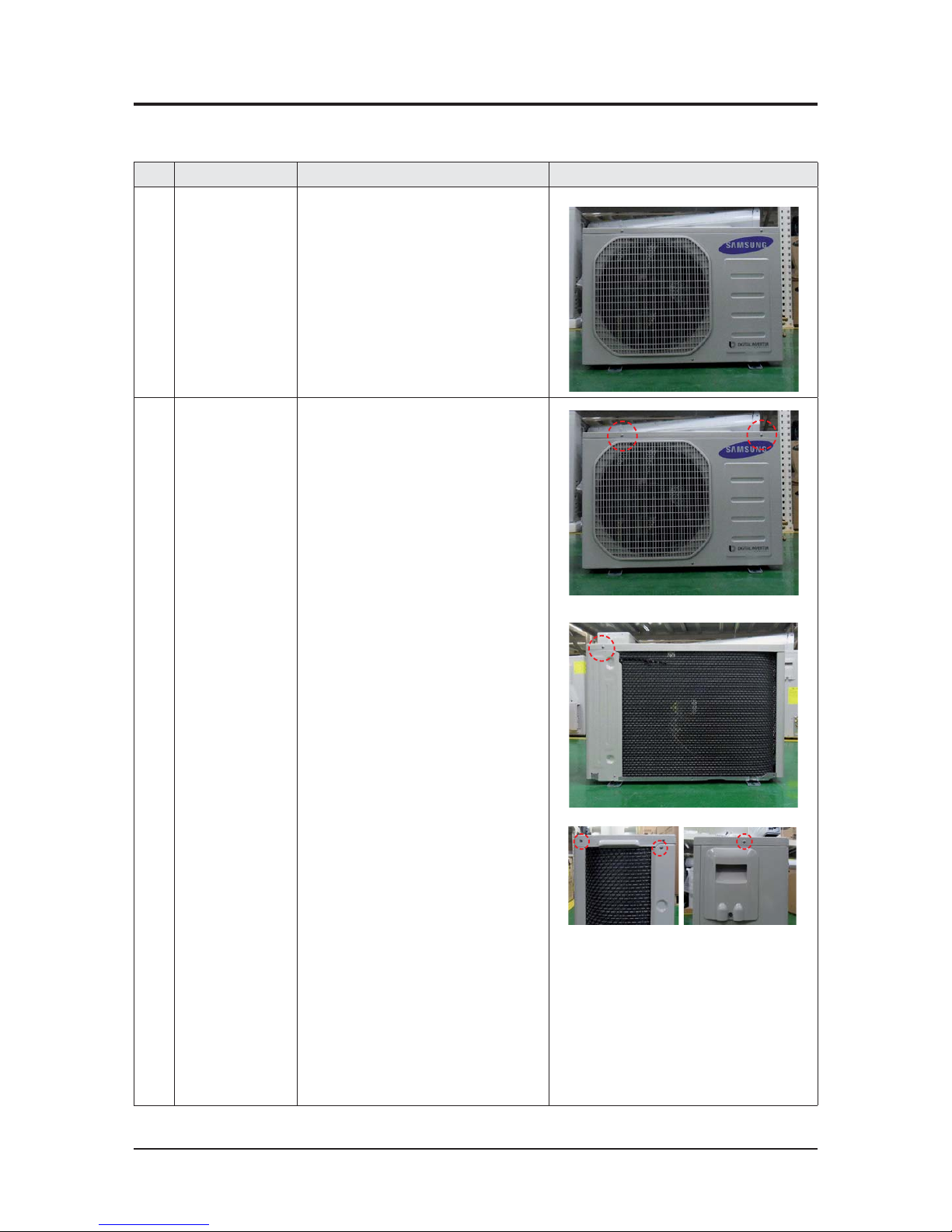
3-2 Outdoor Unit
䒲 AC036/052JCADEC Series
No Parts Procedure Remark
1 1) Stop the operation of air conditioner and
shut off the main power.
2 Assy Cabi Top 1) loosen 6 pcs screw and detach the Assy
Cabi Top.

3-16 Samsung Electronics
No Parts Procedure Remark
3 Assy Cover Control 1) loosen 1 pcs screw and detach the Assy
Cover Control.
4 Assy Cabi Side RH 1) Loosen 2 pcs screws fixed to assemble
Control Box with Cabinet-Side RH.
2) Loosen fixing 7 pcs screws and detach the
Cabinet-Side RH.

Samsung Electronics 3-17
No Parts Procedure Remark
5 Guard Cond 1) Loosen 1 pcs screw and detach the Guard
Cond.
6 Assy Cabinet Front 1) Loosen 5 pcs screws and detach the Assy
Cabinet Front.

3-18 Samsung Electronics
No Parts Procedure Remark
7 Fan & Motor,
Bracket Motor
1) loosen the 1 nut according the indication and
detach the fan propeller.
2) Disconnect the Motor wire from Assy Control
Out.
3) Loosen 4 pcs screws and detach the Motor.
4) Loosen 5 fixing screws and detach the Bracket
Motor.

Samsung Electronics 3-19
No Parts Procedure Remark
8 Assy Control Out 1) Detach several connectors from the Assy
Control Out.
2) Loosen 1 pcs screws fixed to assemble
Control Box with Assy Partition and detach
the Assy Control Out.

3-20 Samsung Electronics
No Parts Procedure Remark
9 Thermister 1) Disconnect the thermister wire from Assy
Control Out.
2) Detach the temperature sensor assembled
to pipe & heat exchanger.
10 Reactor 1) Loosen 3 pcs screws and detach the
Reactor.

Samsung Electronics 3-21
No Parts Procedure Remark
11 Compressor
Remove the refrigerant surely before
compressor disassembly.
1) Disassemble the Felt Compressor Sound.
2) Loosen the fixing nut and detach the
Compressor Lead Wire.
3) Disassemble the pipes in both Discharge
pipe and Suction Pipe with welding torch.
4) Loosen the 3 nuts at the bottom of
Compressor.

3-22 Samsung Electronics
No Parts Procedure Remark
12 Tube Parts
(Assy Tube Suction,
Assy Tube Discharge,
Assy Tube EEV)
1. Remove the refrigerant surely before pipe
disassembly.
2. Disassemble EEV Coil before work when
you replace EEV.
3. Please weld after wrapping head with a
towel and others so that EEV head is not
heated, when you replace EEV.
1) Loosen 4 bolts fixed to assemble Valve
Service with Bracket Valve.
2) Disassemble the serevel pipe with welding
torch.
13 Heat Excharger
Remove the refrigerant surely before Heat
Exchanger.
1) Loosen fixing screw on both sides.
2) Disassemble the pipes in both inlet and
outlet with welding torch.
3) Detach the Heat Exchanger.

Samsung Electronics 3-23
䒲 AC071JCADEC Series
No Parts Procedure Remark
1 common work 1) Stop the operation of air conditioner
and shut off the main power.
2 Assy Cabi Top 1) loosen 8 pcs screw and detach the Assy
Cabi Top.

3-24 Samsung Electronics
No Parts Procedure Remark
3 Assy Cover Control
1)
loosen 1 pcs screw and detach the Assy
Cover Control.
4 Assy Cabi Side RH
1)
Loosen 2 pcs screws fixed to assemble
Control Box with Cabinet-Side RH.
2)
Loosen fixing 7 pcs screws and detach the
Cabinet-Side RH.

Samsung Electronics 3-25
No Parts Procedure Remark
5 Guard Cond
1)
Loosen 1 pcs screw and detach the Guard
Cond.
6 Assy Cabinet Front
1)
Loosen 7 pcs screws and detach the Assy
Cabinet Front.

3-26 Samsung Electronics
No Parts Procedure Remark
7 Fan & Motor, Bracket
Motor
1)
loosen the 1 nut according the indication
and detach the fan propeller.
2)
Disconnect the Motor wire from Assy
Control Out.
3) Loosen 4 pcs screws and detach the Motor.
4)
Loosen 2 fixing screws and detach the
Bracket Motor.

Samsung Electronics 3-27
No Parts Procedure Remark
8 Assy Control Out
1)
Detach several connectors from the
Assy Control Out.
2)
Loosen 2 pcs screws fixed to assemble
Control Box with Assy Partition and detach
the Assy Control Out.
9 Thermister
1) Disconnect the thermister wire from
Assy Control Out.

3-28 Samsung Electronics
No Parts Procedure Remark
2)
Detach the temperature sensor assembled
to pipe & heat exchanger.

Samsung Electronics 3-29
No Parts Procedure Remark
10 Reactor 1) Loosen 3 pcs screws and detach the
Reactor.
11 Compressor
Remove the refrigerant surely before
compressor disassembly.
1) Disassemble the Felt Compressor Sound.
2) Loosen the fixing nut and detach the
Compressor Lead Wire.
3) Disassemble the pipes in both Discharge
pipe and Suction Pipe with welding torch.
4) Loosen the 3 nuts at the bottom of
Compressor.

3-30 Samsung Electronics
No Parts Procedure Remark
12 Tube Parts
(Assy Tube Suction,
Assy Tube Discharge,
Assy Tube EEV)
1. Remove the refrigerant surely before pipe
disassembly.
2. Disassemble EEV Coil before work when
you replace EEV.
3. Please weld after wrapping head with a
towel and others so that EEV head is not
heated, when you replace EEV.
1) Loosen 4 bolts fixed to assemble Valve
Service with Bracket Valve.
2) Disassemble the serevel pipe with welding
torch.

Samsung Electronics 3-31
No Parts Procedure Remark
13 Heat Excharger
Remove the refrigerant surely before
Heat Exchanger.
1) Loosen fixing screw on both sides.
2) Disassemble the pipes in both inlet and
outlet with welding torch.
3) Detach the Heat Exchanger.

Samsung Electronics 4-1
4. Troubleshooting
4-1 Setting an indoor unit address and installation option
▶ Set the indoor unit address and installation option with remote controller option.
Set the each option separately since you cannot set the ADDRESS setting and indoor unit installation setting option at the
same time.You need to set twice when setting indoor unit address and installation option.
4-1-1 The procedure of setting option
Step 2
Option setting procedure. (The option setting procedure is the same for other models.)
After entering the option setting status, select the option as listed below.
Step 1
Entering mode for option setting.
1. Remove batteries from the remote controller.
2. Insert the batteries while you press [+ Temperature] and [- Temperature] button at the same time.
3. Check if you have entered the option setting status.
High Temp Button
High Fan Button
Mode change
Low Temp Button
Low Fan Button
Entering mode for
setting option
Option setting mode
t 0QUJPOTFUUJOHJTBWBJMBCMFGSPN4&(UP4&(
t 4&(4&(4&(4&(BSFOPUTFUBTQBHFPQUJPO
t 4FUUIF4&(_4&(4&(_4&(JOUIF0/TUBUVTBOE4&(_4&(_JOUIF0''TUBUVT
SEG1 SEG2 SEG3 SEG4 SEG5 SEG6 SEG7 SEG8 SEG9 SEG10 SEG11 SEG12
0XXXXX1XXXXX
SEG13 SEG14 SEG15 SEG16 SEG17 SEG18 SEG19 SEG20 SEG21 SEG22 SEG23 SEG24
2XXXXX3XXXXX
0O4&(_ 0ò4&(_

4-2 Samsung Electronics
4-1-2 The procedure of setting option
Option setting Status
1. Setting SEG2, SEG3 option
Press Low Fan button(
) to enter SEG2 value.
Press High Fan button(
) to enter SEG3 value.
Each time you press the button,
p p … p will be selected in rotation .
SEG2 SEG3
2. Setting Cool mode
Press Mode button to be changed to Cool mode in the ON status .
3. Setting SEG4, SEG5 option
Press Low Fan button(
) to enter SEG4 value.
Press High Fan button(
) to enter SEG5 value.
Each time you press the button,
p p … p will be selected in rotation .
SEG4 SEG5
4. Setting Dry mode
Press Mode button to be changed to DRY mode in the ON status .
5. Setting SEG6, SEG8 option
Press Low Fan button(
) to enter SEG6 value.
Press High Fan button(
) to enter SEG8 value.
Each time you press the button,
p p … p will be selected in rotation .
SEG6 SEG8
6. Setting Fan mode
Press Mode button to be changed to FAN mode in the ON status .
7. Setting SEG9, SEG10 option
Press Low Fan button(
) to enter SEG9 value.
Press High Fan button(
) to enter SEG10 value .
Each time you press the button,
p p … p will be selected in rotation .
SEG9 SEG10
8. Setting Heat mode
Press Mode button to be changed to HEAT mode in the ON status .
9. Setting SEG11, SEG12 option
Press Low Fan button(
) to enter SEG11 value .
Press High Fan button(
) to enter SEG12 value.
Each time you press the button,
p p … p will be selected in rotation .
SEG11 SEG12
10. Setting Auto mode
Press Mode button to be changed to AUTO mode in the OFF status.
11. Setting SEG14, SEG15 option
Press Low Fan button(
) to enter SEG14 value.
Press High Fan button(
) to enter SEG15 value.
Each time you press the button,
p p … p will be selected in rotation.
SEG14 SEG15

Samsung Electronics 4-3
The procedure of setting option (cont.)
Option setting Status
12. Setting Cool mode
Press Mode button to be change to Cool mode in the OFF status.
13. Setting SEG16, SEG17 option
Press Low Fan button(
) to enter SEG16 value.
Press High Fan button(
) to enter SEG17 value.
Each time you press the button,
p p … p will be selected in rotation.
SEG16 SEG17
14. Setting Dry mode
Press Mode button to be change to Dry mode in the OFF status.
15. Setting SEG18, SEG20 option
Press Low Fan button(
) to enter SEG18 value.
Press High Fan button(
) to enter SEG20 value.
Each time you press the button,
p p … p will be selected in rotation.
SEG18 SEG20
16. Setting Fan mode
Press Mode button to be change to Fan mode in the OFF status.
17. Setting SEG21, SEG22 option
Press Low Fan button(
) to enter SEG21 value.
Press High Fan button(
) to enter SEG22 value.
Each time you press the button,
p p … p will be selected in rotation.
SEG21 SEG22
18. Setting Heat mode
Press Mode button to be change to HEAT mode in the OFF status.
19. Setting SEG23, SEG24 mode
Press Low Fan button(
) to enter SEG23 value.
Press High Fan button(
) to enter SEG24 value.
Each time you press the button,
p p … p will be selected in rotation.
SEG23 SEG24

4-4 Samsung Electronics
Step 3. Check the option you have set
After setting option, press button to check whether the option code you input is correct or not.
Step 4. Input option
Press the operation button with the direction of remote control for set.
For the correct option setting, you must input the option twice.
Step 5. Check operation
1) Reset the indoor u
nit by pressing the RESET button of indoor unit or outdoor unit.
2) Take the batteries out of the remote controller and insert them again and then press the operation
button.
→
→
→
→
→
→
→
→
→

Samsung Electronics 4-5
1. If you want to use the various additional functions for your Wired Remote Controller, press the Set and Esc buttons at the
same time for more than three seconds.
Ź
You will enter the additional function settings, and the [main menu] will be displayed.
2. Refer to the list of additional functions for your Wired Remote Controller on the next page, and select the desired menu.
Ź
Using the [ఴ]/[వ] buttons, select a main menu number and press the [] button to enter the sub-menu setting screen.
Ź
Using the [ఴ]/[వ]
buttons, select a sub-menu number and press the [] button to enter data setting screen.
Ź
When you enter the setting stage, the current setting will be displayed.
Ź
Refer to the chart for data settings.
Ź
Using the [ఴ]/[వ] buttons, sel
ect the settings. Press the [] button to move to the next setting.
Ź
Press the Set button to save the settings and exit to the sub-menu setting screen.
Ź
Press the Esc button to exit to normal mode.
t8IJMFTFUUJOHUIFEBUBZPVDBOVTFUIF<]/[] buttons to set the range of Data bit.
t8IJMFDPOGJHVSJOHUIFTFUUJOHQSFTTUIFEsc button to exit to the setting sub-menu without saving your changes.
4-1-3 Order for Setting Options (Wired Remote Controller)
Main Menu
Sub-menu
1 2 3546
SEGs for Use

4-6 Samsung Electronics
4-1-4 Setting an indoor unit installation option
(Suitable for the condition of each installation location)
1. Check whether power is supplied or not.
- When the indoor unit is not plugged in, there should be additional power supply in the indoor unit.
2. The panel(display ) should be c onnected to an indoor unit to receive option.
3.
Set the installation option according to the installation condition of an air conditioner.
- The default setting of an indoor unit installation option is 02000-100000-200000-300000.
- Individual control of a remote controller(SEG20) is the function that controls an
indoor unit individually when there is more
than one indoor unit.
4. Set the indoor unit option by wireless remot e controller.
▶
Drain pump(SEG8) will be set to ‘USE + 3 minute delay’ even if the drain pump is set to 0.
▶
Number of hours using lter(SEG18) will be set to ‘1000 hour’ even if the SEG18 is set to except for 2 or 6.
▶
*GZPVJOQVUBOVNCFSPUIFSUIBO_PGUIFJOEJWJEVBMDPOUSPMPGUIFJOEPPSVOJU4&(UIFJOEPPSJTTFUBTiJOEPPSw
SEG1 SEG2 SEG3 SEG4 SEG5 SEG6
0 2 RESERVED
Exterior temperature
sensor
Central control RESERVED
SEG7 SEG8 SEG9 SEG10 SEG11 SEG12
1 Drain pump RESERVEDRESERVEDRESERVEDRESERVED
SEG13 SEG14 SEG15 SEG16 SEG17 SEG18
2External control
External control
output
S-Plasma ion Buzzer
Number of hours
using lter
SEG19 SEG20 SEG21 SEG22 SEG23 SEG24
3
Individual control of
a remote controller
RESERVEDRESERVEDRESERVEDRESERVED
Indoor Unit
1(L)
F2
F1
2(N)

Samsung Electronics 4-7
Option No. : 02XXXX-1XXXXX-2XXXXX-3XXXXX
Option SEG1 SEG2SEG3 SEG4 SEG5 SEG6
Explanation PAGE MODE
RESERVED
Use of external
temperature sensor
Use of central control
RESERVED
Remote
Controller
Display
Indication
and Details
Indication Details Indication Details Indication Details Indication Details
0 2
0 Disuse 0 Disuse
1Use1Use
Option SEG7 SEG8 SEG9 SEG10 SEG11 SEG12
Explanation PAGE Use of drain pump
RESERVED RESERVED RESERVED RESERVED
Remote
Controller
Display
Indication
and Details
Indication Details Indication Details
1
0 Disuse
1Use
2
Use +
3minute
delay
Option SEG13 SEG14 SEG15 SEG16 SEG17 SEG18
Explanation PAGE Use of external control
Setting the output of
external control
S-Plasma ion Buzzer control
Remote
Controller
Display
Indication
and Details
Indication Details Indication Details Indication Details Indication Details Indication Details Indication Details
2
0 Disuse 0 Thermo on 0 Disuse 0
Use of
buzzer
2 1000 Hour
1
ON/OFF
Control
1
Operation
on
1Use1
Non use of
buzzer
6 2000 Hour
2
OFF
Control
3
Window
ON/OFF
Control
Option SEG19 SEG20 SEG21 SEG22 SEG23 SEG24
Explanation PAGE
Individual control of a
remote controller
RESERVED RESERVED RESERVED RESERVED
Remote
Controller
Display
Indication
and Details
Indication Details Indication Details
3
0 or 1 Indoor 1
2 Indoor 2
3 Indoor 3
4 Indoor 4

4-8 Samsung Electronics
4-1-5 Changing a particular option
You can change each digit of set option.
t 8IFODIBOHJOHBEJHJUPGBOJOEPPSVOJUBEESFTTTFUUJOHPQUJPOTFUUIF4&(BTA"
t 8IFODIBOHJOHBEJHJUPGJOEPPSVOJUJOTUBMMBUJPOPQUJPOTFUUIF4&(BTA
Ex) When setting the 'buzzer control' into disuse status.
Option
SEG1 SEG2 SEG3 SEG4 SEG5 SEG6
Explanation PAGE MODE
The option mode
you want to
change
The tens’ digit of an
option SEG you will
change
The unit digit of an
option SEG you will
change
Changed value
Indication 0D217 1
Option SEG1 SEG2SEG3 SEG4 SEG5 SEG6
Explanation PAGE MODE
The option mode you
want to change
The tens’ digit of an
option SEG you will
change
The unit digit of an
option SEG you will
change
The changed value
Remote
Controller
Display
Indication
and Details
Indication Details Indication Details Indication Details Indication Details Indication Details Indication Details
0D
Option
mode
0~F
Ten s’ digi t
of SEG
0~9
Unit digit
of SEG
0~9
The
changed
value
0~F

Samsung Electronics 4-9
4-1-6 Option code for each model
Model SEG1 SEG2 SEG3 SEG4 SEG5 SEG6 SEG7 SEG8 SEG9 SEG10 SEG11 SEG12
Remocon
display
AC036JB1DEC0 1 707C110 42D
AC052JB1DEC0 1 807C1 9042C
AC071JB1DEC0 1 807C1 9044C
Model SEG13 SEG14 SEG15 SEG16 SEG17 SEG18 SEG19 SEG20 SEG21 SEG22 SEG23 SEG24
Remocon
display
AC036JB1DEC 2 7 2 80037
5 260
AC052JB1DEC 2 734 00372 5 6 0
AC071JB1DEC 2 7 4 80037F 5 6 0

4-10 Samsung Electronics
4-2 Items to check before diagnostics
4-2-1 Test run mode and View mode
䒲 Display Option Key
ఐ
Short push K2 (Start cooling test mode) ױ Short push 1 more time (Stop cooling test mode and start inverter checker mode)
ױ
Short push 1 more time (Stop inverter checker mode)
S/W Operation Contents
Display
SEG1 SEG2SEG3 SEG4
K2
Short push 1 Cooling test mode
After short push 1
Inverter Checker mode
(For service only)
After short push 1 KEY operation end
K3 Short push 1 Reset
K4
Refer to view mode display
View mode Refer to view mode display
Short
push
Display contents SEG1 SEG2SEG3 SEG4 Unit
1 Order frequency 1 Hundreds' digit Tens' digit Unit digit Hz
2 Current frequency 2 Hundreds' digit Tens' digit Unit digit Hz
3 The number of current indoor units 3 Hundreds' digit Tens' digit Unit digit EA
4 The sensor for outdoor air intake4 + / - Tens' digit Unit digit °C
5 Discharge sensor 5 Hundreds' digit Tens' digit Unit digit °C
6 Eva-Mid sensor 6 + / - Tens' digit Unit digit °C
7 Cond sensor 7 + / - Tens' digit Unit digit °C
8 Current 8 Tens' digit Unit digit
decimals
A
9 Fan RPM 9
Thousands'
digit
Hundreds' digit Tens' digit rpm
10 Target discharge temperature A Hundreds' digit Tens' digit Unit digit °C
11 EEV B Hundreds' digit Tens' digit Unit digit step
12 The capacity sum of indoor units C Tens' digit Unit digit
decimals
kW
13 Protective control D
0: Cooling
1: Heating
Protective control
0: No Protective control
1: Freezing
2: Non-stop defrosting
3: Over-load
4: Discharge
5: Total electric current
Frequency status
0: Normal
1: Hold
2: Down
3: Up_limit
4: Down_limit
-
14
The temperature of heat radiating plate
E Hundreds' digit Tens' digit Unit digit -
15
The number of connected indoor units
F- - - -
Long push 1 Main micom version Year (Hex) Month (Hex) Date (Tens' digit) Date (Unit digit)
After short push 1 Inverter micom version Year (Hex) Month (Hex) Date (Tens' digit) Date (Unit digit)
After short push 1 E2P version Year (Hex) Month (Hex) Date (Tens' digit) Date (Unit digit)
❋ Long push K4(Main micom ver.) short push 1 more(Inv. micom ver.) short push 1 more(E2P. ver.)

4-11 Samsung Electronics
Error Mode
LED Display
Ca
u
Operation Timer
SPi Filter
Blue Green BlueBlueBlue
Power Reset XXXXAbnormal power.
Error on room temperature sensor of indoor unit (Short or Open)
(E121)
XX
XXIndoor unit temperature
s
Error on Eva-in sensor of indoor unit (Short or Open)(E122)
Error on Eva-out sensor of indoor unit (Short or Open)(E123)
X XXIndoor unit heat exchang
e
Indoor fan error (E154) :
Under 450 RPM for more than 15 seconds
XX X
X
Restriction of indoor unit
f
Low speed operation of i
n
Error of outdoor unit
Error of the terminal block thermal fuse (Open) (E198)
X X
Outdoor unit error occurs
Terminal Block thermal fu
Error on float switch (2nd detection)(E153) XXX
Check the float sensor
EEPROM circuit failure (E162)
Faulty of EEPROM parts.
Faulty of EEPROM circuit
p
EEPROM option error (E163) Blockage of outdoor unit
v
Communication error between indoor unit and outdoor unit(E101) XX X
2 minutes no communica
unit and outdoor unit.(Co
more than 2 minutes)
Communication error after tracking due to unmatching number of
installed units(E201)
XX
X
After complete Trackin
g
of the indoor unit nu
communicated error
disconnection)
Communication error between indoor unit and outdoor unit(E202)
When there is no respon
s
tracking is completed
Communication error between outdoor unit inv - main
micom(E203)
Communication error be
main micom
Blockage detected on high pressure pipe (E422)
XX Blockage of outdoor unit
v
4-2-2 Troubleshooting for indoor unit
䒲 Error detection and reoperation
1. If an error occurs during operaion, the LED flashers to indicate that there is a problem then all operations stop except LED.
2. When resuming operation with remote controller and switch, it determines error mode after normal operation.
䒲 1way cassette(AC666JB1DEC Series)

Samsung Electronics 4-12
se Action to take
Judgement Method
Reset Power
ensor Open/Short.
Check the connection of indoor unit main PCB and sensor wire.Check open/short of indoor unit
main PCB, sensor parts pattern and parts.
427 page
e
r Open/Short.
Check the connection of indoor unit main PCB and sensor wire.
Check open/short of indoor unit main PCB, sensor parts pattern and parts.
428 page
f
an motor.
door unit fan motor.
Check the connection of indoor unit main PCB and fan motor wire.
Check the restriction of indoor unit fan motor.
Check the normal/fault of indoor unit fan motor.
429 page
/
se error(Open)
Check the condition of out door unit error.
Check open of Terminal Block
thermal fuse connection wire.
Check the connection of indoor unit main PCB and sensor wire.
Check abnormality of float sensor unit.
431 page
art.
Check insufficient-solder/cold-solder/short/parts non-mounting of IC202 parts PIN.
Check insufficient-solder/cold-solder/short/parts non-mounting of IC202 circuit periphery parts.
432 page
v
alve Check the Blockage of outdoor unit valve
tion between the indoor
mmunication error for Check electrical connection and setting between indoor unit and outdoor unit 443 page
5 times, missmatching
mbers set with those
(some of indoor unit
Check electrical connection and setting between indoor unit and outdoor unit
e from indoor units after
Check electrical connection and setting between indoor unit and outdoor unit 430 page
tween outdoor unit inv -
Check electrical connection and setting between indoor unit MAIN PBA - INVERTER PBA
v
alve Check the Blockage of outdoor unit valve
: On
: Flashes X : OFF

4-13 Samsung Electronics
Option
SEG19 SEG20 SEG21 SEG22 SEG23 SEG24
Explanation
PAGE
Individual control of
a remote controller
Heating setting
compensation
RESERVED
Motion detect
sensor
RESERVED
Indication
and
Details
Indication
Details
Indication
Details
0 Disuse
Indication
Details
3
0 or 1Indoor 1
0.No Use (Factory Setting)
1. Standard Mode/Auto
Set OFF30 Min.
2. Standard Mode/Auto
Set OFF60 Min.
3. Standard Mode/Auto
Set OFF 120 Min.
4. Standard Mode/Auto
Set OFF 180 Min.
5. Premium Mode/Auto
Set OFF30 Min.
6. Premium Mode/Auto
Set OFF60 Min.
7. Premium Mode/Auto
Set OFF 120 Min.
8. Premium Mode/Auto
Set OFF 180 Min.
2Indoor 2
3 Indoor 3
4Indoor 4
1
2ԕʹ
2
5ԕʹ
X If you input a number other than 0~4 on the individual control of the indoor unit(SEG 20), the indoor is set as
"Indoor 1".
Example) If you want to set as "Exterior temperature sensor : USE, External control : USE, Number of hours using ler :
2000hr", assign option codes except SEG 1, 7, 13, 19 which are page options.
SEG1 SEG2 SEG3 SEG4 SEG5 SEG6
0 2-10 -
SEG7 SEG8 SEG9 SEG10 SEG11 SEG12
1 0 ---0
SEG13 SEG14 SEG15 SEG16 SEG17 SEG18
210 - 0 6
SEG19 SEG20 SEG21 SEG22 SEG23 SEG24
30----
▶
1WAY/2WAY/4WAY MODEL : Drain pump(SEG8) will be set to 'USE + 3minute delay' even if the drain pump is set to 0.
▶
1 WAY/2WAY/4WAY, DUCT MODEL : Number of hours using lter(SEG18) will be set to '1000hour' even if the SEG18 is set to
exept for 2 or 6.
▶
*GZPVJOQVUBOVNCFSPUIFSUIBO_PGUIFJOEJWJEVBMDPOUSPMPGUIFJOEPPSVOJU4&(UIFJOEPPSJTTFUBTJOEPPS
▶
4WAY MODEL : Even when the value of Heating setting compensation(SEG21) is set to '0', it wil be recognized as '5°C'.

Samsung Electronics 4-14
You can change each digit of set option.
Option
SEG1 SEG2 SEG3 SEG4 SEG5 SEG6
Explanation
PAGE MODE
The option mode
you want to
change
The tens ’ digit of an
option SEG you will
change
The unit digit of
an option SEG you
will change
The changed value
Indication
and
Details
Indication
Details
Indication
Details
Indication
Details
Indication
Details
Indication
Details
Indication
Details
0D
Option
mode
_'
Tens’ digit
of SEG
_
Unit digit
of SEG
_
The
changed
value
_'
t 8IFODIBOHJOHBEJHJUPGBOJOEPPSVOJUBEESFTTTFUUJOHPQUJPOTFUUIF4&(BTA"
t 8IFODIBOHJOHBEJHJUPGJOEPPSVOJUJOTUBMMBUJPOPQUJPOTFUUIF4&(BTA
Ex) When setting the 'buzzer control' into disuse status.
Option
SEG1 SEG2 SEG3 SEG4 SEG5 SEG6
Explanation PA GE MODE
The option
mode you want
to change
The tens ’ digit of
an option SEG
you will change
The unit digit of
an option SEG
you will change
The changed
value
Indication 0D 217 1
4-2-3 Changing a particular option

4-15 Samsung Electronics
4-2-4 Option code for each model
Model OPTION CODE
ACN026NDEHA/EU 015077-166 0F8-271A21-370000
ACN035NDEHA/EU 015077-166 219-272328-370000
ACN052NDEHA/EU 015077-17625D-273437-370040
ACN060NDEHA/EU 015077-18626E-273C46-370040
ACN071NDEHA/EU 015077-156391-274750-370040
ACN026NDEHH/SA01
5077-166 0F8-271A21-370000
ACN035NDEHH/SA 015077-16 6219-272328-370040
ACN052NDEHH/SA 015077-17625D-273437-370040
ACN060NDEHH/SA 015077-18626E-273C40-370040
AC026FBNDEH/EU 015077-1960C8-271A21-370000
AC035FBNDEH/EU 015077-1860F9-2
72328-370000
AC052FBNDEH/EU 015077-17625D-273437-370040
AC060FBNDEH/EU 015077-18626E-273C46-370040
AC071FBNDEH/EU 015077-166 381-274750-370040
NS0261DXEA 017057-1860F8-2 71A23-370010
NS0351DXEA 017057-17624
D-272328-370010
AC026FB1DEH/EU 017057-1760F8-271A23-370010
AC035FB1DEH/EU 017057-18624D-272328-370010

4-16 Samsung Electronics Samsung Electronics 4-17
4-3 Items to check before diagnostics
4-3-1 Four directions cassette type
Error Mode
Cause Measures
Product operation with error
Diagnosis method
Operation Defrost Timer Filter
Outdoor Unit
compressor
Outdoor Unit
fan
indoor Unitheat
fan
XXXPower reset - operation-off operation-off operation-off -
X
XX
Error of room temperature sensor in the indoor
unit (Open/Short)
t$IFDLJOEPPSUFNQFSBUVSFTFOTPSDPOOFDUJPO
t$IFDLJOEPPSUFNQFSBUVSFTFOTPSTSFTJTUBODFWBMVFUPTFFJGJUTTIPSUPQFO
operation-off operation-off operation-off -
XX
Error of heat exchanger IN/OUT sensor in the
indoor unit (Open/Short)
t$IFDL&7"*/065TFOTPSDPOOFDUJPO
t$IFDL&7"*/065TFOTPSTSFTJTUBODFWBMVFUPTFFJGJUTTIPSUPQFO
operation-off operation-off operation-off -
XX
XError of fan motor in the indoor unit
t$IFDLUIFDPOOFDUJPOPGNPUPSDPOOFDUPS
t$IFDLUIFTQFFEPGUIFNPUPSGBO
operation-off operation-off operation-off -
X X
Error of the outdoor temperature sensor
Error of the condensor temperature sensor
Error of the discharge temperature sensor
t$IFDLPVUEPPSUFNQFSBUVSFTFOTPSDPOOFDUJPO
t$IFDLPVUEPPSUFNQFSBUVSFTFOTPSTSFTJTUBODFWBMVFUPTFFJGJUTTIPSUPQFO
operation-off operation-off operation-off -
X
X
No communication for 2 minutes between indoor
and outdoor unit (communication error for more
than 2 minutes)
t$IFDLDPOOFDUJPOCFUXFFOJOEPPSBOEPVUEPPSVOJUDPNNVOJDBUJPODBCMFT operation-off operation-off operation-off -
X
Error of outdoor unit t$IFDLFSSPSPDDVSSFEXJUIPVUEPPSVOJU operation-off operation-off operation-off -
XX
Detection of the float switch
t$IFDLGMPBUTXJUDIDPOOFDUJPO
t$IFDLXIFUIFSUIFESBJOIBTCFFOGJMMFEXJUIXBUFS
operation-off operation-off operation-off -
XEEPROM err or t$IFDLJGUIFSFJTEBNBHFXJUI&&130.DPNQPOFOU operation-off operation-off operation-off -
EEPROM option error
t$IFDLUIFJOEPPSNPEFMUPTFUUIFPQUJPOT
t*OTQFDUJPOGPSNBUDICFUXFFOJOEPPSBOEPVUEPPSNBDIJOFNPEFMT
operation-off operation-off operation-off -
XX
.%4LJUFSSPS
$IFDLUIFXJSFDPOOFDUJ PO
$IFDLUIF.%4,*5
$IFDLUIFJOEPPS1#"
operation-on operation- on operation-on
-
4-11
لTurn onስFlashingΉTurn off

4-18 Samsung Electronics
4-3-2 Test run mode and View mode
䒲
Display Option Key
KEY KEY operation 7-segment display
K1
Press once : Heating test run
i
[Comparison of weights with other compani
e
HAUZEN
Other compani
e
Weight
20Kg
17kg
35%
29kg
wi wi#-"/,wi#-"/,w
Press twice : Defrost test run
i
[Comparison of weights with other compani
e
HAUZEN
Other compani
e
Weight
20Kg
17kg
35%
29kg
wi wi#-"/,wi#-"/,w
K2 Press once : Cooling test run
i
[Comparison of weights with other compani
e
HAUZEN
Other compani
e
Weight
20Kg
17kg
35%
29kg
wi wi#-"/,wi#-"/,w
K3 Reset
K4 View mode Refer to View mode display
䒲 VIEW mode display
Number
of press
Display contents
Display
Units
Segment 1 Segment 2 Segment 3 Segment 4
1 Order frequency 1Three digits Two digits One digit Hz
2 Current frequency 2Three digits Two digits One digit Hz
3Number of indoor heat exchangers 3 Three digits Two digits One digit Hz
4 Out sensor 4Two digits One digit First decimal °C
5 Discharge sensor 5 Two digits One digit First decimal °C
6 OLP sensor 6Two digits One digit First decimal °C
7 Cond sensor 7 Two digits One digit First decimal °C
8Current 8 Two digits One digit First decimal C
9 Fan RPM 9 Three digits Two digits One digit rpm
10 Target discharge temperature A Three digits Two digits One digit °C
11 E E V B Three digits Two digits One digit step
12 Total indoor heat
exchanger capacity C Two digits One digit First decimalkW
13Protection control D
0 : air conditioning
1 : heating
Protection control
0 : no protection
control
1 : freezing
2 : non-stop
defrosting
3 : over-load
4 : discharge
Frequency state
0 : Normal
1 : Hold
2 : Down
3 : Up_limit
4 : S
own_limit
-
14
Group address of indoor heat
exchanger
EThree digits Two digits One digit -
15 S/W checkF----
7-segment display
Key Switch

Samsung Electronics 4-19
4-3-3 ECO mode(Power save)
Mode
Display ECO mode lamp
Segment 1 Segment 2 Segment 3 Segment 4 RED color
ECO mode i#-"/,w i#-"/,w i#-"/,w i#-"/,w On
Exit ECO mode Press K3 to exit Off
ECO mode lamp : RED

4-20 Samsung Electronics
4-3-4 1 way cassette type
㽞 Error detection and reoperation
1. If an error occurs during operation, the LED flashes to indicate that there is a problem then all operations stop except LED.
2. When resuming operation with remote controller and switch, it determines error mode after normal operation.
㽞LED lamp display when error is detected
Error LED lamp Display
Cause Actions to take
Operation Defrost
XX䢻XX
ח Breakaway from the room temperature
sensor connector.
ח Cut the room temperature sensor wire.
ח Check the connection between the room tem-
perature wire and the main PCB of the indoor
unit.
ח Check the pattern of the room temperature sen-
sor part of the
main PCB of the indoor unit and if
parts are open or shorted.
䢻
X
䢻
XX
ח Disjoint of the in/out sensor connector
of the indoor heat exchanger.
ח Cut the in/out sensor wir e of the
indoor heat exchanger.
ח Check the connection between the room tem-
perature wire and the main PCB of the indoor
unit.
ח Chec
k the pattern of the room temperature sen-
sor part of the main PCB of the indoor unit and if
parts are open or shorted.
XXX䢻X
ח Indoor fan motor is non-operative.
ח Indoor fan motor is operating
slowly.
ח Indoor fan motor operates at an exces-
sive speed.
ח Check if a motor connector has been
dismounted. (CN44. CN73)
ח Check the fastening of the motor fan.
䢻
XX
䢻
X
ח Disjointed or cut off of outdoor tem-
perature sensor.
ח Disjointed or cut off of the outdoor
sensor of heat exchanger (COND).
ח Dismounted/cut off of the outdoor
discharge sensor.
ח Check the PCB display window of the outdoor
unit then refer to a breakdown diag nosis.
XX
䢻䢻
X
ח Communication error between indoor
units and outdoor units for more than
2 minutes.
ח 3 min. error of the outdoor unit track-
ing. (multi-product specification)
ח Inconsistency between the number
of installed units and communication
units. (multi-product
specification)
ח Check the connection between indoor and out-
door units
ח Check the settings for indoor Main/RMC address
switch
XX
䢻䢻䢻
ח The detection of secondary high tem-
perature at COND.
(out door heat exchanger)
ח The detection of secondary high tem-
perature at discharge.
ח Reverse detection error.
ח Check the PCB display window of the outdoor
unit then refer to breakdown diagnosis.
XXX
䢻䢻
ח Deviation of float sensor connector.
ח Cut of float sensor wire.
ח Check the connection between main PCB and
float sensor in the indoor unit.
لTurn onስFlashingΉTu rn off

Samsung Electronics 4-21
Error LED lamp Display
Cause Actions to take
Operation Defrost
䢻
X
䢻䢻
X
ח EEPROM part defect
ח EEPROM circuit defect
ח
Check non-delivery/cool delivery/non-insertion of IC51
Part Pin.
ח
Check non-delivery/cool delivery/non-insertion of IC51
peripheral circuit components.
䢻䢻䢻䢻䢻
ח EEPROM option none input/error
input.
ח
Re-input of option code for indoor unit.
لTurn onስFlashingΉTu rn off
㽞LED lamp display when error is detected

4-22 Samsung Electronics
4-3-5 Troubleshooting for outdoor unit
No.
Error Code
Meaning Remarks
1 E121 Error on room temperature sensor of indoor unit (Short or Open)
Indoor unit Room Thermistor Open/Short
2
E122
Error on EVA IN sensor of indoor unit (Short or Open)
Indoor unit EVA_IN Thermistor Open/Short
3 E123
Error on EVA OUT sensor of indoor unit (Short or Open) Indoor unit EVA_OUT Thermistor Open/Short
4
E153
Error on float switch (2nd detection)
Indoor unit Float Switch Open/Short
Drain
Pump operation Check.
5 E154Indoor fan error
Check on indoor unit indoor Fan operation
6E198 Error on thermal fuse of indoor unit (Open)
Thermal Fuse Open Check of indoor unit
Terminal Block
7 E201
Communication error between indoor unit and outdoor unit
(Pre tracking failure or when actual number of indoor units are
different from
the indoor unit quantity setting on the outdoor
unit) Error due to communication traking failure after initial
power is supplied. (The error occurs regardless of the number
of units.)
Check indoor quantity setting in outdoor
8 E202
Communication error between indoor unit and outdoor unit
(When there is no response from indoor units after tracking is
completed)
Check electrical connection and setting between indoor unit and outdoor
unit
9 E203
"Communication error between outdoor unit inv - main micom
'PS1'_DPOUSPMMFSFSSPSXJMMCFEFUFSNJOFEGSPNUIFUJNF
when compressor is turned on)"
Check electrical connection and setting between indoor unit MAIN PBA -
INVERTER PBA
10 E221 Error on outdoor temperature sensor (Short or Open) Check Outdoor sensor Open / Short
11 E231Error on outdoor COND OUT sensor (Short or Open)
Check Cond-Out sensor Open / Short
12
E251
Error on discharge temperature sensor of compressor 1 (Short or
Open)
Check Discharge sensor Open / Short
13 E320
Error on OLP sensor (Short or Open)
Check OLP sensor Open / Short
14
E403
Compressor down due to freeze protection control
Check Outdoor Cond.
15 E404
System stop due to overload protection control Check Comp. when it start
16 E416 System stop due to discharge temperature -
17 E422 Blockage detected on high pressure pipe
1. Check if the service valve is open
2. Check for refrigerant leakage(pipe
connections, heat exchanger) and
charge refrigerant if necessary
3. Check if there's any blockage on
refrigerant cycle(indoor unit/
outdoor
unit)
4. Check if additional refrigerant has
been added after pipe extension
18 E425Reverse phase or open phase
Check whether 3 phase is reversed or
opened.
19 E440
Heating operation restricted at outdoor temperature over
Theat_high value (default: 30
C)
HEATING
20 E441
Cooling operation restricted at outdoor temperature below
Tcool_low value (default: 0 C)
COOLING
21 E458 Fan speed error FAN1 ERROR
22 E461 Error due to operation failure of inverter compressor -
23 E462 System stop due to full
current control-

Samsung Electronics 4-23
No.
Error Code
Meaning Remarks
24 E463Over current trip / PFC over curr en t error Check OLP sensor
25 E464 IPM Over Current(O.C) IPM
26 E465 Comp. Over load error -
27 E466 DC-Link voltage under/over error Check AC Power and DC Link Voltage
28 E467
Error due to
abnormal rotation of the compressor or uncon-
nected wire of compressor
Check Comp wire
29 E468 Error on current sensor (Short or Open) Check Outdoor Inverter PBA.
30 E469 Error on DC-Link voltage sensor (Short or Open) -
31E470 Outdoor unit EEPROM Read/Write error (Option) Check Ou
tdoor EEPROM Data
32E471 Outdoor unit EEPROM Read/Write error (H/W) Check Outdoor EEPROM PBA
33 E474Error on IPM Heat Sink sensor of inverter 1 (Short or Open) Check Outdoor Inverter PBA.
34E475 Error on inverter fan 2FAN2 ERROR
35 E483 H/W DC_Link Over Voltage
Error Check AC Power
36E484
PFC Overload (Over current) Error Check Outdoor Inverter PBA.
37 E485 Error on input current sensor of inverter 1 (Short or Open)
38 E488 AC Input Voltage Sensor Error
Check Outdoor Inverter PBA
39 E500 IPM over heat error on inverter 1 Check Outdoor Inverter PBA.
40 E554Gas leak detected Check the refrigerant
41 E556
Error due to mismatching capacity of indoor and outdoor
unit
Check the indoor and Outdoor unit
Capacity
42 E557 DPM remote controller option error Check
the indoor option code
43 E590 Inverter EEPROM CheckSum error -

4-24 Samsung Electronics
4-3-6 Wired remote controller
- If an error occurs, ( ) icon will be displayed on the wired remote controller.
- Press the Test button to see the error code.
Error mode Contents Measure
Product operation in
error condition
Error type
Outdoor unit/
Compressor/Indoor
unit
Indoor unit communication error
Check the communication cable of indoor
unit. Check the DC output voltage at the
communication terminal
Operation Off
Communication
error
Indoor unit Eva In sensor
(Open/Short)
Check indoor unit pipe sensor. Check indoor
PCB connector CN41(White)
Operation Off Indoor sensor error
Indoor unit Eva In sensor
(Open/Short)
Check indoor unit pipe sensor.
Check indoor PCB connector CN413(White)
Operation Off Indoor sensor error
Indoor unit Eva In sensor
disconnection
Check the disconnection of indoor unit pipe
sensor
Operation Off Indoor sensor error
Remocon Option for MDS is set for
ON, but MDS kit is disconnected or
the signals for sensors are abnormal.
Check the wire connection
Check the MDS kit
Check the main PBA
Normal operation
(without MDS kit)
MDS kit Error
Indoor floating switch secondary
detection
Check indoor unit float sensor. Check indoor
PCB connector CN5 (black)
Operation Off
Self diagnostic
error
Indoor fan error Check on indoor unit indoor fan operation Operation Off
Self diagnostic
error
Error on thermal fuse of indoor unit
(Open)
Thermal fuse open check of indoor unit
terminal block
Operation Off
Indoor unit
protection control
error.
Communication error after tracking
due to unmatching number of
installed units
Check indoor quantity setting in outdoor Operation Off
Communication
error
Indoor/outdoor communication
error (1 min)
Check the communication connection
between indoor and outdoor units. Check
the power line and communication cable
connection status
Operation Off
Communication
error
Communication error between
indoor/outdoor INV
׳
MAIN MICOM (1 min)
Check MAIN MICOM
Check INVERTER MICOM
-
Communication
error
Outdoor temperature sensor error
Check sensor connection status
Check sensor location
Check sensor resistance
Operation Off
Outdoor sensor
error
Error on outdoor COND OUT sensor
(Short or Open)
Check sensor connection status
Check sensor location
Check sensor resistance
Operation Off
Outdoor sensor
error
[Inverter] Emission temperature
sensor error
Check sensor connection status
Check sensor location
Check sensor resistance
Operation Off
Outdoor sensor
error
Error on OLP sensor (Short or Open)
Check sensor connection status
Check sensor location
Check sensor resistance
Operation Off
Outdoor sensor
error
Compressor down due to freeze
protection control
Check outdoor cond. Operation Off
Outdoor unit
protection control
error.
System stop due to overload
protection control
Check compressor when it start Operation Off
Outdoor unit
protection control
error.

Samsung Electronics 4-25
Wired remote controller (cont.)
Error mode Contents Measure
Product operation in
error condition
Error type
Outdoor unit/
Compressor/Indoor
unit
Emission temperature excessively
high
No error (DISCHARGE temperature control) -
Outdoor unit
protection control
error
High pressure blockage error
(Refrigerant completely Leakage
error)
Check whether the outdoor unit service valve
is open.
Check the connection of the pipes.
Check the operation of the EEV.
Check for refrigerant leakage.
(Completely leakage).
Operation Off
Self
diagnostic
error
Reverse phase or open phase
Check whether 3 phase is reversed or opened.
Check EMI PBA fuse
Operation Off
Outdoor unit
protection control
error.
Heating operation blocked
Check the operation setting state
Check temperature sensor
Operation Off
Self diagnostic
error
Cooling operation blocked
Check the operation setting state
Check temperature sensor
Operation Off
Self diagnostic
error
Outdoor fan 1 error
Check input power connection status
Check the connection status between the
motor and outdoor unit PCB
Check indoor/outdoor fuse
Operation Off
Self diagnostic
error
[Inverter] Compressor startup error
Check the compressor connection status
Check the resistance between difference
phases of the compressor
Operation Off
Outdoor unit
protection control
error
[Inverter] Total current error/
PFC over current error
Check the input power
Check the coolant charging status
Check the normal operation of outdoor fan
Operation Off
Outdoor unit
protection control
error
Over current trip/
PFC over current error
Check service valve open
Check pipe connections leakage.
Check outdoor location and orientation.
Operation Off
Outdoor unit
protection control
error.
[Inverter] IPM over current error
Check coolant charging
Check the compressor connection status and
normal operation
Check the obstacles around the indoor and
outdoor units
Check whether the outdoor unit service valve
is open
Check whether the indoor/outdoor installation
pipe/wiring are correct
Operation Off
Outdoor unit
protection control
error
Compressor V limit error
Check the compressor connection status
Check the resistance between difference
phases of the compressor
Operation Off
Outdoor unit
protection control
error
DC LINK over/low voltage error
Check input power
Check AC power connection
Restart in 3 minutes
Outdoor unit
protection control
error
[Inverter] Compressor rotation error
Check the compressor connection status
Check the resistance between difference
phases of the compressor
Operation Off
Outdoor unit
protection control
error
[Inverter] Current sensor error
Check EEPROM DATA
Check the normal operation of PCB
Operation Off
Outdoor unit
protection control
error

4-26 Samsung Electronics
Wired remote controller (cont.)
Error mode Contents Measure
Product operation in
error condition
Error type
Outdoor unit/
Compressor/Indoor
unit
[Inverter] DC LINK voltage sensor
error
Check the input power connection
Check the status of RY21 and R200 in the
INVERTER PCB
Operation Off
Outdoor unit
protection control
error
[Inverter] OTP error
Check EEPROM DATA
Check the normal operation of PCB
Operation Off
Outdoor unit
protection control
error
Error on IPM Heat Sink sensor of
inverter 1 (Short or Open)
Check outdoor inverter PBA Operation Off
Outdoor sensor
error
Outdoor fan 2 error
Check the input power connection status
Check the connection status of the motor and
the outdoor unit PCB
Check the indoor/outdoor unit fuse
Operation Off
Self diagnostic
error
H/W DC_Link Over Voltage Error
Check AC power
Check reactor wire
Check outdoor PBA
Operation Off
Outdoor unit
protection control
error.
PFC Overload (Over current) Error Check outdoor inverter PBA Operation Off
Outdoor unit
protection control
error.
Error on input current sensor of
inverter 1 (Short or Open)
- Operation Off
Outdoor sensor
error
AC Input Voltage Sensor Error
Check AC power
Check reactor wire
Check outdoor inverter PBA
Operation Off
Outdoor sensor
error
IPM over heat error on inverter 1 Check outdoor inverter PBA Operation Off
Outdoor unit
protection control
error.
Gas leak error
Check the coolant charging status
Check the indoor EVA sensor
Check if the outdoor unit service value is open
Check that the indoor/outdoor installation
pipe/wiring are correct
Operation Off
Self diagnostic
error
Capacities not matched Check the option code of the indoor unit Operation Off
Outdoor unit
protection control
error
Inverter EEPROM CheckSum error Check outdoor PBA Operation Off
Self diagnostic
error
Communication error between
the indoor unit and wired remote
controller
Check the connection wire between the indoor
unit and the wired remote controller
Normal operation
Wired remote
controller error
Communication error between
the Master and Slave wired remote
controllers
Check the option switch for defining the
Master and Slave (only one Master and one
Slave can exist)
Normal operation
Wired remote
controller error
COM1/COM2 cross installation error
Check that wired remote controller is
connected to the COM2 terminal of the indoor
unit
Normal operation
Wired remote
controller error
Wired remote controller COM2
option setting error
Check that Com1, Com2 setting DIP switch is
set to Com2
Normal operation
Wired remote
controller error

Samsung Electronics 4-27
Indoor unit display
4Way
X (Operation) (Defrost) X (Timer) X (Filter)
1Way
X (Operation) X (Defrost) (Reservation) X (Fan) X (Filter)
Symptom
In case of open or short circuit of indoor temperature sensor
Failure
Short or leakage of the corresponding sensor
Yes
No
No
In this case, is the resistance
value out of range in the temperature
table on the right?
Yes
Is indoor temperature
sensor disconnected from the
connector in PCB?
Restart the system after replacing the PCB
Restart the system after connecting
to the PCB connector
Indoor temperature sensor
failure (replace)
Remove the indoor temperature sensor
connector from the PCB and measure the
resistance between two terminals
4-4 Troubleshooting by symptoms
4-4-1 Indoor temperature sensor (open/short)(E121)
Current
temperature
(°C)
Resistance
(k)
40 5.800
35 6.900
30 8.300
25 10.00
20 12.10
15 14.70
10 18.00
5 22.00
0 28.30
-5 33.90
-10 42.30
<Temperature sensor
resistance value>

4-28 Samsung Electronics
Yes
No
No
In this case, is the resistance
value out of range in the temperature table
on the right?
Yes
Is the indoor heat exchanger
temperature sensor connector disconnected
from the PCB?
Restart the system after replacing the PCB
Restart the system after
connecting the connector to PCB
Failure of the indoor heat
exchanger temperature sensor
(replace)
Remove the indoor heat exchanger
temperature sensor connector from
the PCB and measure the resistance
between two terminals
Indoor unit display
4way
(Operation) (Defrost) X (Timer) X (Filter)
1way
(Operation) X (Defrost) (Reservation) X (Fan) X (Filter)
Symptom
Short or open circuit of indoor heat exchanger temperature sensor
Failure
Short or open circuit in the corresponding sensor
4-4-2 Indoor heat exchanger temperature sensor (open/short) (E122)
Current
temperature
(°C)
Resistance
(k)
40 5.800
35 6.900
30 8.300
25 10.00
20 12.10
15 14.70
10 18.00
5 22.00
0 28.30
-5 33.90
-10 42.30
<Temperature sensor
resistance value>

Samsung Electronics 4-29
Indoor unit display
4way
X (Operation) X (Defrost) (Timer) X (Filter)
1way
X (Operation) X (Defrost) X (Reservation) (Fan) X (Filter)
Symptom
Indoor unit fan does not run /Runs at excessive high speed and stops
Failure
Check if the motor connector is disconnected/ check the motor fan assembly status
4-4-3 Indoor FAN error (E154)
Check the normal
operation.
No
Is the motor connector(CN73)
disconnected from the PCB?
Connect the
connector to PCB
Yes
No
Does the motor rotates when operating?
Motor ᐯ׳ᐱ :
*TWPMUBHFPG%$7_%$7EJTQMBZFE
Check the PCB and
replace it
Is the RPM of motor less
than 120?
Yes
During operation or Operation at the beginning :
E154 is displayed.
No
Check the motor and
replace it.
Yes
Ex) Depending on FAN RPM, voltage of
%$7_%$7JTPVUQVU
↓ ↓
1 2 3 4 5 6
[ 4-way cassette type ]
Check the normal
operation.
No
Is the motor connector(CN73 or CN44)
disconnected from the PCB?
Connect the
connector to PCB.
Yes
No
[After the start of operation of FAN]
Motor ᐯ׳ᐱ : Is voltage of
AC 220V displayed?
Check the PCB and replace it.
Yes
Check the motor and
replace it.
[1 way cassette type]

4-30 Samsung Electronics
Indoor unit display
4way
X (Operation) (Defrost) (Timer) X (Filter)
1way
X (Operation) X (Defrost) (Reservation) (Fan) X (Filter)
Symptom
Communication error between the indoor and outdoor unit for two minutes
Failure
Communication error between the indoor unit and outdoor unit
4-4-4 Communication error after finishing Tracking (E202)
No
Yes
No
Yes
Is there a response from the indoor PCB?
(LED01 (RED) is not ON)
In this case, is the
voltage waveform between the lines square
wave with amplitude over ±0.7V as shown
in the following picture?
+0.7V
-0.7V
Good
Bad
Check the communication cable and
replace the indoor unit PCB
Remove the communication cable
connecting the outdoor unit to indoor unit,
and measure the signal on LINE 2 of the
outdoor unit with a scope
Reconnect the cable connecting
the outdoor unit to the indoor unit
and restart the unit.
If the communication still doesn’t work,
replace the indoor unit PCB.
Check the communication
cable in the outdoor unit PCB
and replace the PCB
LED01

Samsung Electronics 4-31
Indoor unit display
4way
X (Operation) X (Defrost) (Timer) (Filter)
1way
X (Operation) X (Defrost) X (Reservation) (Fan) (Filter)
Symptom
The indoor unit floating sensor is open and that state is maintained for more than one minute.
Failure
Increase in the drain pan water level due to failure of the indoor unit drain pump,
or float sensor failure.
4-4-5 Indoor unit float sensor error (E153)
No
No
No
Yes
Yes
Yes
Yes
Yes
Remove the floating sensor
connector connected to the indoor unit
PCB and the resistance measured between the
two terminals. Is the resistance ∞?
(open circuit)
Is the water level in the drain pan high?
Does drain pump operate
when compressor operates?
Same error occurs again
No
Is the water level in
drain pan decreasing?
Reset the indoor unit power and
check the operation of the drain pump.
(it vibrates when operating)
Normal operation
Replace the indoor unit PCB
Reassemble the floating sensor
connector and reset the outdoor unit power.
(Indoor unit power reset is required)
Normal operation
Replace the floating sensor
when it fails and reset the
indoor unit power
Replace the drain pump
Error occurs
Float sensor error is released when
indoor unit power is reset.
Use AC drain pump.
Which one of AC drain pump
and DC drain pump is used?
DC drain pump PCB unit
(CN76) voltage = around DC 12V ?
DC AC drain pump
PCB unit(CN74)
voltage = around AC 12V ?
Replac AC drain pump
Replace indoor unit PBA
Replac DC drain pump
Use DC drain pump.
Replace indoor unit PBA
Yes
Yes
No

4-32 Samsung Electronics
Indoor unit
display
4way
(Operation) (Defrost) (Timer) X (Filter)
1way
AC
666
JB1DEC6except
AC
666
MN1DKH6except
(Operation) X (Defrost) (Reservation) (Fan) X (Filter)
1way
AC
666
JB1DEC6only
AC
666
MN1DKH6only
(Operation) (Defrost) (Reservation) (Fan) (Filter)
Symptom
EEPROM circuit failure
Failure
EEPROM component failure, EEPROM circuit parts missing/damaged/soldering failure
4-4-6 EEPROM circuit failure (E162)
Restart the unit after replacing the PCB
No
Yes
Are the EEPROM circuit
components in good conditions?
(missing components / damage /
soldering failure)
Replace the PCB if the restart fails
AC666JB1DEC6(only)
AC666MN1DKH6(only)
AC666JB1DEC6 except
AC666MN1DKH6 except
EEPROM Reassembly
Remove short or
unsoldering
Replace EEPROM PBA
No
No
Yes
Yes
Is EEPROM SUB PBA reassembled correctly?
Is any problem such as short or unsoldering
between EEPROM PIN?
Turn on the unit.
162 Occurs.
EEPROM PBA CODE
: DB93-12483A

Samsung Electronics 4-33
Indoor unit display 1way
AC666JB1DEC6 except
AC
666
MN1DKH6except
X (Operation) X (Defrost) (Reservation) (Fan) (Filter)
Symptom
Thermal Fuse Open Error
Failure
Check the connection of the CN140 wire.
Check the connection of the terminal block.
(Temperature rise by untightening a screw/ Termal Fuse open)
4-4-7 Thermal Fuse Open Error
E198 occurs.
Measure both ends of connector
connected the TERMINAL BLOCK.
Replace the MAIN PBA.
No
No
Yes
Is the CN140 connector of
PCB between wire correctly
connected?
Paragraph (Short) Has the connector ends?
Re-operation after the connector.

Samsung Electronics 5-1
PCB Diagram and Parts List
5. PCB Diagram and Parts List
5-1 Indoor Unit
5-1-1 Slim 1 way cassette type
■ 1way cassette(AC036JB1DEC6, AC026/036MN1DKH6)
22
1 2 3 4 5 16 11 17 6 18 7 19
8 20
9
12
14
13
23 15 21 10

PCB Diagram and Parts List
5-2 Samsung Electronics
1way cassette(AC036JB1DEC6,AC026/036MN1DKH6) (cont.)
①
#1: GND
②
#1: POWER(N)
#3 : SSR MOTOR POWER(L)
#5 : POWER(N)
③
#1: FUSE CHECK SIGNAL
#2: GND
④
#1 : ROOM THERMISTOR
#2 : GND
⑤
#1: DC12V
#2: LED_0
#3: LED_1
#4: LED_2
#5: LED_3
#6: LED_4
#8: REMOCON_OUTPUT_SIGNAL
#9 : AUTO SWITCH
#10: REMOCON_INPUT_SIGNAL
#11: GND
#12: DC5V
#13: GND
⑥
#1: DC12V
#2: GND
⑦
#1: GND
#2: EXT-CTRL SIGNAL
⑧
#1 : EVA-IN THERMISTOR
#2 : GND
#3 :
EVA-OUT THERMISTOR
#4 : GND
#5 : DISCHARGE THERMISTOR
#6 : GND
⑨
#1: F/S SIGNAL
#2: GND
⑩
#1: D/ P POWER(DC12V)
#2: GND
⑪
#1: DC12V
#2: ERROR SIGNAL OUTPUT(GND)
#3: DC12V
#4: COMP/OPER. SIGNAL OUT
PUT(GND)
⑫
#1: GND
#3: DC5V
#4: EEPROM_SELECT
#5: EEPROM_SO
#6: EEPROM_SI
#7: EEPROM_CLK
⑬
⑭
#1: DC12V
#2: VENT SIGNAL OUTPUT(GND)
⑮
#1: DC12V
#2: HUMAN SENSOR COMM(TXD)
#3: HUMAN SENSOR COMM(RXD)
#4: GND
⑯
#1:
GND
#2: GND
#3: SPI POWER OUTPUT(DC12V)
⑰
#1 : DC5V
#2 : GND
#3 : MOTOR FEEDBACK
⑱
#1 : DC12V
#2~#5: LOUVER SIGNAL OUTPUT
#6 : DC12V
#7~#10: LOUVER SIGNAL OUTPUT
⑲
#1 : DC12V
#2~#5:
LOUVER SIGNAL OUTPUT
⑳
#1 : DC12V
#2~#5: LOUVER SIGNAL OUTPUT
㉑
#1~#4: EEV SIGNAL OUTPUT
#5 : DC12V
#6 : DC12V
㉒
#1: POWER(L)
#2: POWER(N)
㉓
#1: COM1(F1)
#2: COM1(F2)
#3: V1(DC12V)
#4: V2(GND)
#5:
COM2(F3)
#6: COM2(F4)
CN101-GND CN701-FAN MOTOR CN140-FUSE CHECK CN412-ROOM THERMISTOR
CN501-DISPLAY CN301-DOWNLOAD CN83-E XT CTRL CN413:THERMISTOR
CN411-FLOAT SWITCH CN103-DRAIN PUMP CN81-ERROR /COMP CHECK CN201-EEPROM
CN311-2WIRED REMOCON CN804-VENTILATOR CN401-HUMAN SENSING CN801-SPI
CN702-HALL IC CN806 -SLIDE 2/3 CN2-SLIDE 1 CN805-LOUVER
CN808-EEV TB101-AC POWER TE04-COMMUNICATION

Samsung Electronics 5-3
PCB Diagram and Parts List
■ 1way cassette(AC052/071JB1DEC6)
22 1 2 3 4 16 5 11 6 7 8 20 10 13 15 23
17 18 19 912 21 14

PCB Diagram and Parts List
5-4 Samsung Electronics
1way cassette(AC052/071JB1DEC6) (cont.)
①
#1: GND
②
#1: DC310V
#3 : GND
#4 : DC15V
#5 : FAN RPM
#6 : RPM FEEDBACK
③
#1: FUSE CHECK SIGNAL
#2: GND
④
#1 : DC12V
#4 : REMOCON SIGNAL
#5 : GND
⑤
#1: DC12V
#2: LED_0
#3: LED_1
#4
: LED_2
#5: LED_3
#6: LED_4
#7: LED_5
#8: REMOCON_OUTPUT_SIGNAL
#9 : AUTO SWITCH
#10: REMOCON_INPUT_SIGNAL
#11: GND
#12: DC5V
#13: GND
⑥
⑦
#1: GND
#2: EXT-CTRL SIGNAL
⑧
#1 : EVA-IN THERMISTOR
#2 : GND
#3 : EVA-OUT THERMISTOR
#4 : GND
#5 : DISCHARGE THERMISTOR
#6 : GND
⑨
#1: F/S SIGNAL
#2: GND
⑩
#1: D/ P POWER(DC12V)
#2: GND
⑪
#1: DC12V
#2: ERROR SIGNAL OUTPUT(GND)
#3: DC12V
#4: COMP/OP
ER. SIGNAL OUTPUT(GND)
⑫
#1: GND
#3: DC5V
#4: EEPROM_SELECT
#5: EEPROM_SO
#6: EEPROM_SI
#7: EEPROM_CLK
⑬
⑭
#1: DC12V
#2: VENT SIGNAL OUTPUT(GND)
⑮
#1: DC12V
#2: HUMAN SENSOR COMM(TXD)
#3: HUMAN SENSOR COMM(RX
D)
#4: GND
⑯
#1:ROOMTHERMISTOR
#2:GND
⑰
#1~#4: EEV SIGNAL OUTPUT
#5 : DC12V
#6 : DC12V
⑱
#1 : DC12V
#2~#5: LOUVER SIGNAL OUTPUT
⑲
#1 : DC12V
#2~#5: LOUVER SIGNAL OUTPUT
#6 : DC12V
#7~#10: LOUVER SIGNAL OUTPUT
⑳
#1:DC12V
#2~#5:LOUVERSIGNALOUTPUT
㉑
#1: GND
#2: GND
#3: SPI POWER OUTPUT(DC12V)
㉒
#1: POWER(L)
#2: POWER(N)
㉓
#1: COM1(F1)
#2: COM1(F2)
#3: V1(DC12V)
#4: V2(GND)
#5: COM2(F3)
#6: COM2(F4)
CN101-GND CN701-BLDC MOTOR CN140-FUSE CHECK CN809-AUTO GRILL
CN501-DISPLAY CN301-DOWNLOAD CN83-EX T CTRL CN413:THERMISTOR
CN411-FLOAT SWITCH CN103-DRAIN PUMP CN81-ERROR /COMP CHECK CN201-EEPROM
CN311-2WIRED REMOCON CN804-VENTILATOR CN401-HUMAN SENSING CN412-ROOM THERMISTOR
CN808-EEV CN807-LOUVER5 CN806-LOUVER3/4 CN805-LOUVER1/2
CN801-SPI TB101-AC POWER TE04-COMMUNICATION

Samsung Electronics 5-5
PCB Diagram and Parts List
5-1-2 PANEL PCB
■ 1way cassette
1
①
#1 : CN01- INDOOR UNIT MAIN PBA
CONNECTION
#1,#2,#3,#4,#5 : DISPLAY LED CONTROL
#6: NOT USED
#7: RECEIVE REMOCON SIGNAL
DC Connector

PCB Diagram and Parts List
5-6 Samsung Electronics
17 6 7 1 16 2 11 4 13 12 3 5 8 14 9 1510
■ Main PCB
- AC036/052JCADEC6
5-2 Outdoor Unit

Samsung Electronics 5-7
PCB Diagram and Parts List
①
#1-7: SEGMENT SIGNAL
#8-10: KEY INPUT SIGNAL
②
#1: KEY INPUT SIGNAL
#2-5: GRID SIGNAL
#6-10: REPEATER SIGNAL
③
#1 : DC 12V
#2 : GND
#3 : DC 5V
#4-5: COMM SIGNAL
④
#1 : GND
#2 : NOT USED
#3 : DC5V
#4 :
ENABLE
#5 : RX
#6 : TX
#7 : CLOCK
⑤
#1 : F1
#2 : F2
⑥
#1: OUT TEMP
#3: DISCHARGE TEMP
#5: COND TEMP
#7: OLP TEMP
⑦
#1-4: EEV-A CONTROL SIGNAL
#5 : DC12V
⑧
#1 : DC 310V
#2 :
NOT USED
#3 : AGND
#4 : DC 15V
#5 : CONTROL SIGNAL
#6 : FEED BACK CONTROL
⑨
#1: 4WAY CONTROL SIGNAL
#2: NOT USED
⑩
#1 : DC 15V
#2 : GND
#3 : ENABLE
⑪
#1~20 : DOWNLOAD PORT
⑫
#1 : DC 12V
#2 : GND
#3 : DC 5V
⑬
#1: U
#2: V
#3: W
⑭
#1 : REACTOR1
#2 : REACTOR2
⑮
#1 : NEUTRAL
#2 : LIVE
⑯
⑰
#1-#3: DRED SIGNAL
#4 : GND
#5 : DC 5V
CN206 - SUB DISPLAY
CN205 - SUB DISPLAY
CN207 - SUB DISPLAY
CN551 - INVERTER DOWNLOAD
CN204 - DRED
CN501 - EEPROM PORT
CN301 - 485 COMM CN251 - TEMP SENSOR
EEV-A - EEV VALVE
CN901 - BLDC MOTOR
CN030 - 4WAY VALVE(H/P CN151-INVERTER DC POWER CN551 - MAIN DOWNLOAD CN152 -MAIN DC POWER
CN402 - COMP CN401 - REACTOR CN150 -SMPS AC POWER
Outdoor PCB (cont.)
■ Main PCB
- AC036/052JCADEC6

PCB Diagram and Parts List
5-8 Samsung Electronics
5 6 9 17 7 4 3 2 12 15 14 13
1 11 8 10
16
Outdoor PCB (cont.)
■ Main PCB
- AC071JCADEC6

Samsung Electronics 5-9
PCB Diagram and Parts List
Outdoor PCB (cont.)
■ Main PCB
- AC071JCADEC6
①
#1-7: SEGMENT SIGNAL
#8-10: KEY INPUT SIGNAL
②
#1: KEY INPUT SIGNAL
#2-5: GRID SIGNAL
#6-10: REPEATER SIGNAL
③
#1 : DC 12V
#2 : GND
#3 : DC 5V
#4-5: COMM SIGNAL
④
#1 : GND
#2 : NOT USED
#3 : DC5V
#4 :
ENABLE
#5 : RX
#6 : TX
#7 : CLOCK
⑤
#1 : F1
#2 : F2
⑥
#1: OUT TEMP
#3: DISCHARGE TEMP
#5: COND TEMP
#7: OLP TEMP
⑦
#1-4: EEV-A CONTROL SIGNAL
#5 : DC12V
⑧
#1 : DC 310V
#2 :
NOT USED
#3 : AGND
#4 : DC 15V
#5 : CONTROL SIGNAL
#6 : FEED BACK CONTROL
⑨
#1: 4WAY CONTROL SIGNAL
#2: NOT USED
⑩
#1 : DC 15V
#2 : GND
#3 : ENABLE
⑪
#1~20 : DOWNLOAD PORT
⑫
#1 : DC 12V
#2 : GND
#3 : DC 5V
⑬
#1: U
#2: V
#3: W
⑭
#1 : REACTOR1
#2 : REACTOR2
⑮
#1 : NEUTRAL
#2 : LIVE
⑯
⑰
#1-#3: DRED SIGNAL
#4 : GND
#5 : DC 5V
CN206 - SUB DISPLAY
CN205 - SUB DISPLAY
CN207 - SUB DISPLAY
CN551 - INVERTER DOWNLOAD
CN204 - DRED
CN501 - EEPROM PORT
CN301 - 485 COMM CN251 - TEMP SENSOR
EEV-A - EEV VALVE
CN901 - BLDC MOTOR
CN030 - 4WAY VALVE(H/P) CN151-INVERTER DC POWER CN551 - MAIN DOWNLOAD CN152 -MAIN DC POWER
CN402 - COMP CN401 - REACTOR CN150 -SMPS AC POWER

PCB Diagram and Parts List
5-10 Samsung Electronics
①
#1 : DC 15V
#2 : GND
#3 : ENABLE
②
#1 : NEUTRAL
#2 : LIVE
③
#1 : DC 12V
#2 : GND
#3 : DC 5V
CON03 - INVERTER DC POWER CON01 - SMPS AC POWER CON02 - MAIN DC POWER
1 3
2
Outdoor PCB (cont.)
■ SMPS
- AC666JCADEC6

Samsung Electronics 5-11
PCB Diagram and Parts List
3 1 2
①
#1~7 : SEGMENT SIGNAL
#8~10 : KEY INPUT SIGNAL
②
#1 : KEY INPUT SIGNAL
#2~5 : GRID SIGNAL
#6~10 : REPEATER SIGNAL
③
#1 : DC 12V
#2 : GND
#3 : DC 5V
#4~5 : NOT USED
CN501 - INVERTER PBA CN502 - INVERTER PBA CN205 - SUB DISPLAY
Outdoor PCB (cont.)
■ Sub display
- AC666JCADEC6

Samsung Electronics 6-1
Reference Sheet
Model Code
6. Reference Sheet
6-1 Index for Model Name
6-1-1 Indoor Unit
※
"/" can be removed from the buyer card if there are not enough digits.
Product Type
AM DVM
AJ PMA
AC CAC (USD) / ASD
AE EHS
AN VTL
AK
PAK
(Packaged System)
AG CHR
Separator
SGeneral Set (NASA)
N Indoor unit (NASA)
X Outdoor unit (NASA)
A General Set (Non-NASA)
B
Indoor unit (
Non-
NASA)
C
Outdoor unit (
Non-
NASA)
Chassis Category
FFLAGSHIP
PPREMIUM
DDELUXE <- Basic
SSTANDARD
Separator
11 WAY CST
CST
22 WAY CST
N MINI 4 WAY CST
44 WAY CST
HHSP DUCT
Duct
MMSP DUCT
LLSP DUCT
E
FRESH AIR INTAKE
DUCT
G
CEILING CONCEILED
DUCT
CCEILING
ETCJ CONSOLE
FFLOOR MOUNTING
Rating Voltage
AA(115V, 60hz, 1)
BB(220V, 6 0Hz, 1)
CC(208~230V, 60Hz)
DD(200~220V, 50Hz)
E E(220~240V, 50Hz)
F F(208~230V, 60Hz, 3)
GG(380~415V, 50Hz, 3)
HH(380V, 60Hz, 3)
J J(460V, 6 0Hz, 3)
K K(220~240V, 50/60Hz, 1)
MM(127V, 50Hz)
NN (380~415V, 50/60Hz, 3)
Year
E2012
F2013
G2014
H2015
J2016
Buyer NameCapacity
Mode
C
COOLING ONLY
R410a
H
HEAT PUMP
R
HEAT RECOVERY
D
COOLING ONLY
R22
E
HEAT PUMP
A
Cooling only
R134A
B
Heat Pump
N
N/A
HCH
0
3
3
H6H
J
H
B
H
1
H
D
H
E
H
C
H
/
H
T
H
L
H
A

Reference Sheet
6-2 Samsung Electronics
Index for Model Name (cont.)
Model Code
6-1-2 Outdoor Unit
※
★
MCD: Dummy mock-up model
※
“/” can be removed from the buyer card if there are not enough digits.
Product Type
AM DVM
AJ PMA
AC CAC (USD) / ASD
AE EHS
AN VTL
AK
PAK
(Packaged System)
AG CHR
Separator
SGeneral Set (NASA)
N Indoor unit (NASA)
X Outdoor unit (NASA)
A General Set (Non-NASA)
B
Indoor unit (
Non-
NASA)
C
Outdoor unit (
Non-
NASA)
Chassis Category
FFLAGSHIP
PPREMIUM
DDELUXE <- Basic
SSTANDARD
R UNIVERSAL
Separator
A Inv+Side+General Temp
CAC
S Inv+Side+Low Temp
Q Inv+Side+Tropical Temp
F Inv+Top+Tropical Temp
B Non Inv+Side+General Temp
N Non Inv+Side+Low Temp
R
Non Inv+Side+Tropical
Temp
Z
Non Inv+Top+Tropical
Temp
ࣜ
4Way : 4 , MSP Duct: M , Ceiling: C
Rating Voltage
AA(115V, 60hz, 1)
BB(220V, 6 0Hz, 1)
CC(208~230V, 60Hz)
DD(200~220V, 50Hz)
E E(220~240V, 50Hz)
F F(208~230V, 60Hz, 3)
GG(380~415V, 50Hz, 3)
HH(380V, 60Hz, 3)
J J(460V, 6 0Hz, 3)
K K(220~240V, 50/60Hz, 1)
MM(127V, 50Hz)
NN (380~415V, 50/60Hz, 3)
Year
E2012
F2013
G2014
H2015
J2016
Buyer NameCapacity
Mode
C
COOLING ONLY
R410a
H
HEAT PUMP
R
HEAT RECOVERY
D
COOLING ONLY
R22
E
HEAT PUMP
A
Cooling only
R134A
B
Heat Pump
N
N/A
HCH
0
H3H6H
J
H
C
H
A
H
D
H
E
H
C
H
/
H
T
H
L
H
A

Samsung Electronics 6-3
Reference Sheet
Index for Model Name (cont.)
Model Code
6-1-3 Panel
※
Model name for the column/bundle packaging is “~S”.
★
Only display the Global 4 way with Korean/
English K separator.
H
M
H
S
H
A
H
N
H
C
H
P
H
1N
H
U
Product design classification
P Panel
Product Type
C CST
Product classification
1N Standard 1 way
CST
1B Large-size 1 way
2N 2 WAY
4N 4 WAY
4S MINI 4 WAY
4RRound
★
Panel version
1, 2, .... Korean market use
A, B, ....
Export/
foreign market use
Communication type
1, 2, ....
NASA
485
Color
B Black
E WINE
UWhite
VIvory
★
Language
K Korean
C Chinese
M8 Languages
EEnglish
TYPE
A
Automatic
boarding/slide
S STANDARD
H PREMIUM
Global
4 Way
Panel
Pattern Wae Stripe
Korean
market use
1 5
Export/
foreign
market use
A E

Reference Sheet
6-4 Samsung Electronics
Compressor
Accumulator
Outdoor U n i t
I ndoor Unit
EEV
Heat Exchanger
6-2 Refrigerating Cycle Diagram
Category Symbol Descript ion
Compressor
Rotary Inveter Compressor
Heat Exchanger
Condens ing/Evaporating unit
Accumulator
Accumulator
Valve
Expansion
Electronic Expansion Valve(EEV)
Service
Service valve
Senser Temperature Pip/Air Temperature sensor

This Service Manual is a property of Samsung Electronics Co., Ltd.
Any unauthorized use of Manual can be punished under applicable
International and/or domestic
law.
© Samsung Electronics Co., Ltd. Dec ember. 2016.
Printed in Korea.
Code No. AC-00124E_2
GSPN (GLOBAL SERVICE PARTNER NETWORK)
Area Web Site
Europe, CIS, Mideast & Africa gspn1.samsungcsportal.com
Asia gspn2.samsungcsportal.com
North & Latin America gspn3.samsungcsportal.com
China china.samsungportal.com
 Loading...