

Page 1

8 Channel
16 Channel DVR
User Manual
SRD-830DC/850DC/870DC/
1610DC/1630DC/1650DC/1670DC
Page 2

2_ overview
FEATURES
The SRD DVR (Digital Video Recorder) employs H.264 video encoding for 8 or 16 channel inputs and G.723 audio
encoding for 4 or 16 channels while simultaneously supports hard disc recording and playback.
These DVRs also supports network connectivity, providing remote monitoring from a remote PC transferring video
and audio data.
Provides convenient User Interface
8/16 CH Composite Input Connectors
Supports CIF(S)/2CIF(M)/4CIF(L) recording formats
With the network specific codec, network transfer enabled regardless of the recording conditions
De-interlacing processor for better picture quality
HDMI enabling superior picture output quality
Display of HDD information and status by using HDD SMART
4CIF Size (NTSC: 704*480, PAL: 704*576) Recording in 480 (NTSC)/400 (PAL) IPS speed
(SRD-870DC/1670DC)
CIF(S) Size (NTSC: 352*240, PAL: 352*288) Recording in 480 (NTSC)/400 (PAL) IPS speed (SRD-850DC/1650DC)
CIF(S) Size (NTSC: 352*240, PAL: 352*288) Recording in 240 (NTSC)/200 (PAL) IPS speed (SRD-1630DC)
CIF(S) Size (NTSC: 352*240, PAL: 352*288) Recording in 120 (NTSC)/100 (PAL) IPS speed
(SRD-830DC/1610DC)
8/16-channel Loop Through Video port connection
Hard Disk overwrite function
Mass storage hard disk backup through high-speed USB 2.0
Mass storage hard disk backup through eSATA
(SRD-850DC/870DC/1650DC/1670DC)
Backup function using USB 2.0 flash memory and external CD/DVD writer
Simultaneous Record and Playback of 8/16-channel video data
Various Search Modes (Search by Time, Event, Backup, POS and Motion Detection)
Various Recording Modes (Time Lapse, Event, Scheduled Recording)
Extended Hard Disk Connection (USB 2.0, eSATA) (S
RD-850DC/870DC/1650DC/1670DC)
Alarm Interface (Input: 8/16, Output: 4, Reset: 1)
Remote Monitoring function by Windows Network Viewer
•
•
•
•
•
•
•
•
•
•
•
•
•
•
•
•
•
•
•
•
•
•
overview
Page 3

English _3
OVERVIEW
IMPORTANT SAFETY INSTRUCTIONS
Read these operating instructions carefully before using the unit.
Follow all the safety instructions listed below.
Keep these operating instructions handy for future reference.
Read these instructions.
Keep these instructions.
Heed all warnings.
Follow all instructions.
Do not use this apparatus near water.
Clean only with dry cloth.
Do not block any ventilation openings, Install in accordance with the manufacturer’s
instructions.
Do not install near any heat sources such as radiators, heat registers, stoves, or other
apparatus (including amplifiers) that produce heat.
Do not defeat the safety purpose of the polarized or grounding- type plug. A polarized plug has
two blades with one wider than the other. A grounding type plug has two blades and a third
grounding prong. The wide blade or the third prong are provided for your safety. if the provided
plug does not fit into your outlet, consult an electrician for replacement of the obsolete outlet.
Protect the power cord from being walked on or pinched particularly at plugs, convenience
receptacles, and the point where they exit from the apparatus.
Only use attachments/accessories specified by the manufacturer.
Use only with the cart, stand, tripod, bracket, or table specified by the
manufacturer, or sold with the apparatus. When a cart is used, use
caution when moving the cart/apparatus combination to avoid injury from
tip-over.
Unplug this apparatus during lightning storms or when unused for long
periods of time.
Refer all servicing to qualified service personnel. Servicing is required when the apparatus has
been damaged in any way, such as power-supply cord or plug is damaged, liquid has been
spilled or objects have fallen into the apparatus, the apparatus has been exposed to rain or
moisture, does not operate normally, or has been dropped.
1)
2)
3)
4)
5)
6)
7)
8)
9)
10)
11)
12)
13)
14)
Page 4

4_ overview
overview
BEFORE START
This user manual provides Information for using the DVR such as brief introduction, part names, functions, connection
to other equipment, menu setup, etc.
You have to keep in mind the following notices :
SAMSUNG retains the copyright on this manual.
This manual cannot be copied without SAMSUNG’s prior written approval.
We are not liable for any or all losses to the product incurred by your use of non-standard product or violation of
instructions mentioned in this manual.
Prior to opening the case, please consult a qualified technician first. Whenever this is needed power must be
removed from the unit.
Before installing an additional HDD or connecting an external storage device (USB memory or USB HDD) to this
DVR, check the compatibility. Consult your provider for the compatibility list.
Warning
Battery
It is essential that when changing the battery in the unit, the replacement battery must be of the same type
otherwise there may be a possibility of an explosion.
The following are the specifications of the battery you are using now.
Normal voltage : 3V
Normal capacity : 170mAh
Continuous standard load : 0.2mA
Operating temperature : -20°C ~ +85°C
(-4°F ~ +185°F)
Connect the power cord into a grounded outlet.
The Mains plug is used as a disconnect device and shall stay readily operable at any time.
Batteries shall not be exposed to excessive heat such as sunshine, fire or the like.
System Shutdown
Turning off the power while the product is in operation, or undertaking improper actions may cause damage
or malfunction to the hard drive or the product.
Please turn off the power using the Power button on the front of your DVR.
After selecting <OK> in the pop-up menu, you can pull off the power cord.
You may want to install a UPS system for safe operation in order to prevent damage caused by an
unexpected power stoppage. (Any questions concerning UPS, consult your UPS retailer.)
Operating Temperature
The guaranteed operating temperature range of this product is 0°C ~ 40°C (32°F ~ 104°F).
This product may not work properly if you run right after a long period of storage at a temperature below the
guaranteed one.
Prior to using a device that has been stored for a long period in low temperatures, allow the product to stand
at room temperature for a period.
Especially for the built-in HDD in the product, its guaranteed temperature range is 5°C ~ 55°C (41°F ~ 131°F).
Likewise, the hard drive may not work at a temperature below the guaranteed one.
Ethernet Port
This equipment is in door use and all the communication wirings are limited to inside of the building.
•
•
•
•
•
❖
•
•
•
•
J
❖
❖
❖
CALIFORNIA USA ONLY
This Perchlorate warning applies only to primary CR (Manganese Dioxide)
Lithium coin cells in the product sold or distributed ONLY in California USA.
“Perchlorate Material - special handling may apply,
See www.dtsc.ca.gov/hazardouswaste/perchlorate.”
Page 5
English _5
OVERVIEW
Standards Approvals
This equipment has been tested and found to comply with the limits for a Class A digital device, pursuant to part 15
of the FCC Rules. These limits are designed to provide reasonable protection against harmful interference when the
equipment is operated in a commercial environment.
This equipment generates, uses, and can radiate radio frequency energy and, if not installed and used in accordance
with the instruction manual, may cause harmful interference to radio communications. Operation of this equipment
in a residential area is likely to cause harmful interference in which case the user will be required to correct the
interference at his own expense.
Package Contents
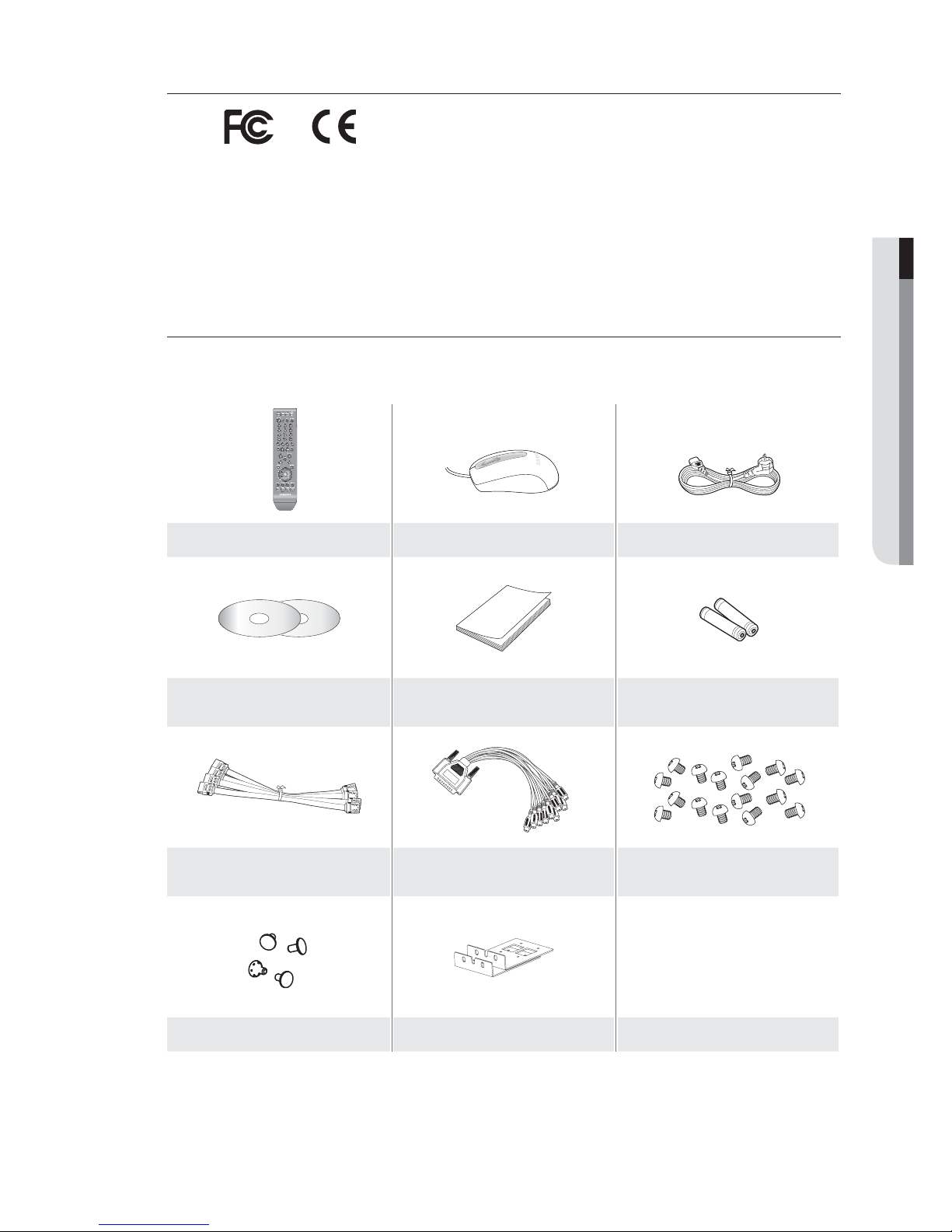
Please unwrap the product, and place the product on a flat place or in the place to be installed.
Please check the following contents are included in addition to the main unit.
Remote Control Mouse Power Cable
Network Viewer Software /
User Manual CD
User Manual Remote Control Battery (AAA)
SATA Cable (4EA)
Audio Extension Cable (optional)
(SRD-850DC/870DC/1650DC/1670DC)
HDD Fixing Screw (16EA)
Bracket Fixing Screw(4EA) Bracket Rack
For models that are not equipped with the HDD, one SATA cable is provided for HDD installation.
M
M
Page 6

6_ overview
overview
CONTENTS
OVERVIEW
2 Features
3 Important Safety Instructions
4 Before Start
8 Part Names and Functions (Front)
10 Part Names and Functions (Rear)
13 Remote Control
INSTALLATION
14 Checking the installation environment
15 Rack Installation
15 HDD Addition
CONNECTING WITH OTHER DEVICE
18 Connecting the Video, Audio, and Monitor
18 Connecting the USB
19 Connecting External SATA HDD
19 Connecting POS Device
19 Connecting the Alarm Input/Output
20 Connecting the RS-485 Device
21 Connecting the Network
LIVE
23 Getting Started
25 Live Screen Configuration
29 Live Mode
31 SPOT Out
32 Zoom
32 Audio ON/OFF
32 Freeze
33 Event Monitoring
USING THE DVR
34 System Setup
44 Setting the Device
52 Setting the Recording
55 Setting the Event
58 Backup
59 Network Configuration
66 Controlling a PTZ device
Page 7

English _7
OVERVIEW
SEARCH & PLAY
68 Search
71 Playback
WEB VIEWER
73 Introducing Web Viewer
74 Connecting Web Viewer
75 Using Live Viewer
81 Using Search Viewer
85 Viewer Setup
95 About
BACKUP VIEWER
96 SEC Backup Viewer
APPENDIX
98 Product Specification (SRD-830DC/1610DC/
1630DC)
101 Product Specification (
SRD-850DC/870DC/
1650DC/1670DC)
104 Product Overview
105 Default Setting
108 Troubleshooting
Page 8

8_ overview
overview
PART NAMES AND FUNCTIONS (FRONT)
830DC/850DC/870DC
1610DC/1630DC/1650DC/1670DC
1234
5678
90
ALARM HDD NETWORK BACKUP REC
DVD RECORDER
REC
ZOOM
MODE
FREEZE
AUDIO
BACKUP
ALRAM
SEARCH
TELE WIDE VIEW PRESET
MENU
RETURN
USB
OPEN/CLOSE
1 3 4
7
10
6 5
2
9 8
1234
5678
9 101112
13 14 15 16
ALARM HDD NETWORK BACKUP REC
DVD RECORDER
REC
ZOOM
MODE
FREEZE
AUDIO
BACKUP
ALRAM
SEARCH
TELE WIDE VIEW PRESET
MENU
RETURN
USB
OPEN/CLOSE
1 3 4
7 6 5
2
9 8
10
Page 9
English _9
OVERVIEW
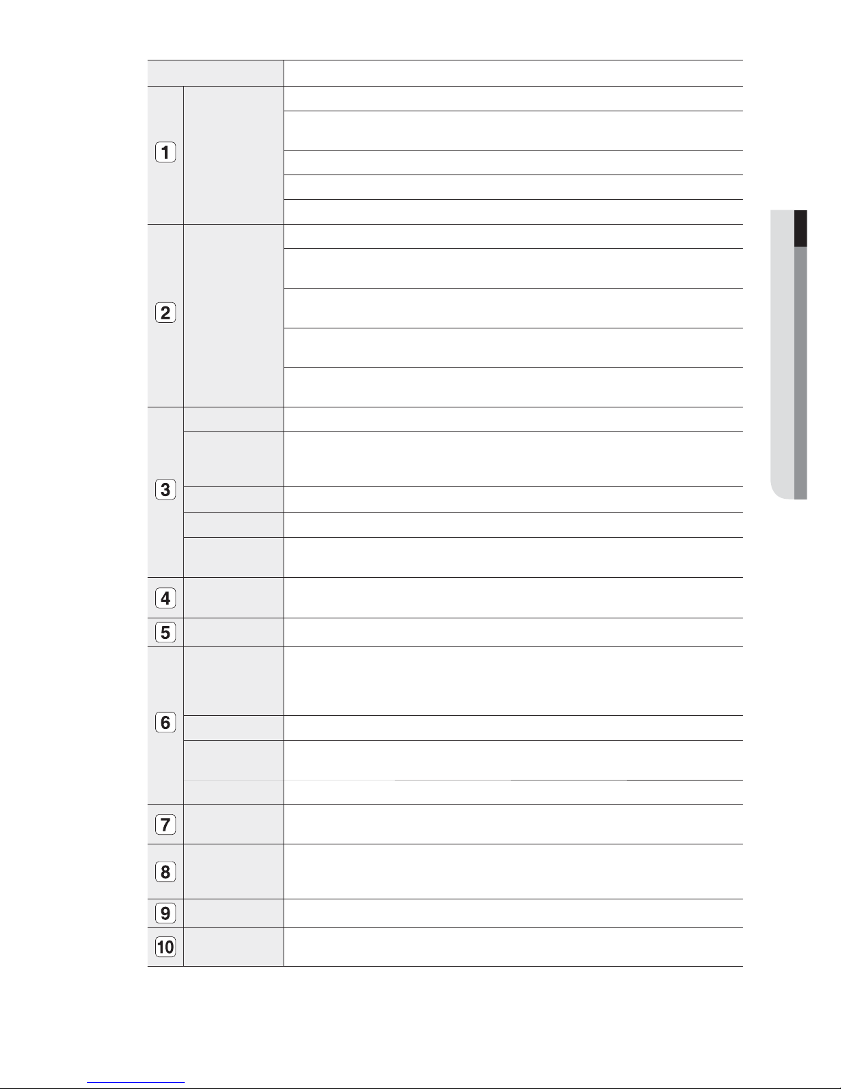
Part Names Functions
LED Indicator
ALARM : Lights on when an event occurs.
HDD : Displays the normal access to HDD.
Upon access to HDD, LED repeats on and off.
NETWORK : Displays both network connection and data transfer status.
BACKUP : Displays when Backup is in progress.
REC : Lights on when recording is in progress.
Camera Control
PTZ : Sets PTZ Mode ON/OFF.
ZOOM(TELE) : Sets the screen to the x2 digital zoom.
Runs the TELE function in the PTZ Mode.
FREEZE(WIDE) : Runs the FREEZE function in the Live Mode.
Runs the WIDE function in the PTZ Mode.
BACKUP(VIEW) : Runs the BACKUP function.
Runs the Preset View function in the PTZ Mode.
SEARCH(PRESET) : Goes to the search screen.
Runs the Preset Setup function in the PTZ Mode.
REC Starts or ends the recording.
/
Step Rewind () : Used for backward frame-by-frame search while in PAUSE.
Fast Rewind () : Used for quick backward search while in Play.
(-x2, -x4, -x8, -x16, -x32, -x64)
Stop : Used to stop the playback.
►/
Play/Pause : Used to pause or resume the screen.
/
Fast Forward () : Used for quick forward playback. (x2, x4, x8, x16, x32, x64)
Step Forward ( ) : Used for forward frame-by-frame search while in PAUSE.
Direction /
Select Button
Used to change a value or move the cursor up/down/left/right (◄ ►).
Selects a menu item or executes the selected menu.
USB Port 1 / 2 Connects the USB devices.
MODE
Each button press in the Live Mode switches the screen to 16-, 9-, 4-, 6-, 8-, 13- split screen,
PIP, and auto sequence mode in order.
In play mode, each press of the button will switch the screen mode to
16-, 9-, 4-, 1-, and
13-split in order. (1 live channel + (N-1) live channel)
AUDIO Sets Audio ON/OFF.
ALARM
Cancels the ALARM LED and the audible alarm when the alarm is going off, and to remove the
icon.
MENU/RETURN Either goes to the system menu screen or moves to the upper menu from the lower menu.
Channel
Used to select channel numbers directly in the Live Mode, or numbers in the numeric input
mode.
Jog shuttle
When a scroll bar appears in each menu, acts as a scrolling.
In Play mode, - Jog : Pauses the playback and steps backward or forward.
- Shuttle : Fast playback forward or backward.
OPEN/CLOSE
Used to open and close the DVR-RW disc tray.
Power
Power LED : Displays the power ON/OFF status.
Power Button : Used to turn the DVR ON/OFF.
Page 10

10_ overview
overview
PART NAMES AND FUNCTIONS (REAR)
830DC
1610DC/1630DC
850DC
1650DC
1
324 5 6 9 10 11 12 1413
1
324 5 6 9 10 11 12 1413
1
324 5 6 7 8 9 10 11 12 1413
1
324 5 6 7 8 9 10 11 12 1413
Page 11
English _11
OVERVIEW
870DC
1670DC
1
324 5 6 7 8 9 10 11 12 1413
1
324 5 6 7 8 9 10 11 12 1413
Page 12
12_ overview
overview
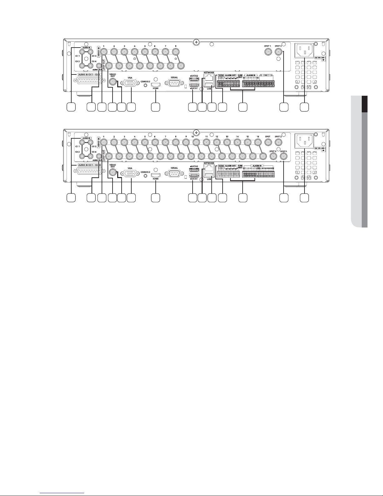
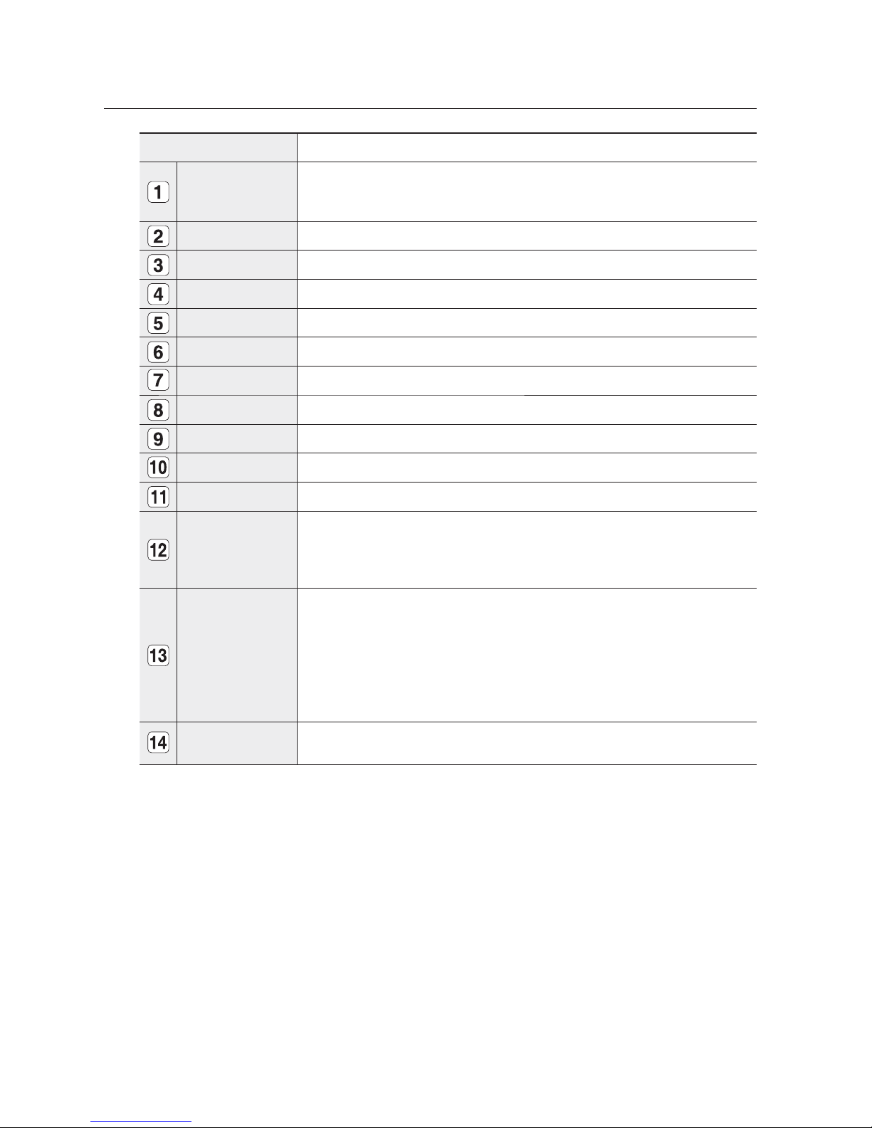
Part Names Functions
AUDIO IN
Audio input signal port (RCA jack) and port for optional audio extension cable.
SRD-1650DC/1670DC (Audio 5~16CH)
SRD-850DC/870DC (Audio 5~8CH)
AUDIO OUT Audio Signal Output Port (RCA jack).
VIDEO IN Composite Video Signal Input Port (BNC type connector).
LOOP OUT Used to transfer a video signal to other video devices.
VIDEO OUT Composite Video Signal Output Port (BNC type connector).
VGA VGA Video Signal Output Port.
HDMI HDMI connector port.
eSATA 1/2 Ports used for external storage device connections. (SATA HDD)
NETWORK NETWORK connector port.
USB USB connector port.
RS-485 Used for RS-485 communication. (TX+, TX-, RX+, RX-)
ALARM
- ALARM IN 1~16(SRD-
1610DC/1630DC/1650DC/1670DC) : Alarm Input port.
- ALARM IN 1~8(SRD-
830DC/850DC/870DC) : Alarm Input port.
- ALARM RESET IN : Alarm Reset port.
- ALARM OUT 1~4 : Alarm Output port.
SPOT
A live screen output port, separate from the VIDEO OUT.
SPOT 1 : Supports Single, 4-, 9-, 16-split, and Auto Sequence modes
SPOT 2 : Supports Single, 4-split, and Auto Sequence modes (only for 5 ~ 8 CH).
SPOT 3 : Supports Single, 4-split, and Auto Sequence modes (only for 9 ~ 12 CH).
SPOT 4 : Supports Single, 4-split, and Auto Sequence modes (only for 13 ~ 16 CH).
SRD-
1670DC : SPOT 1, 2, 3, 4
SRD-
870DC : SPOT 1, 2
SRD-
830DC/850DC/1610DC/1630DC/1650DC : SPOT 1
AC 100-240V~ IN
AC 100 ~ 230V (PAL)
AC 110 ~ 220V (NTSC)
Page 13
English _13
OVERVIEW
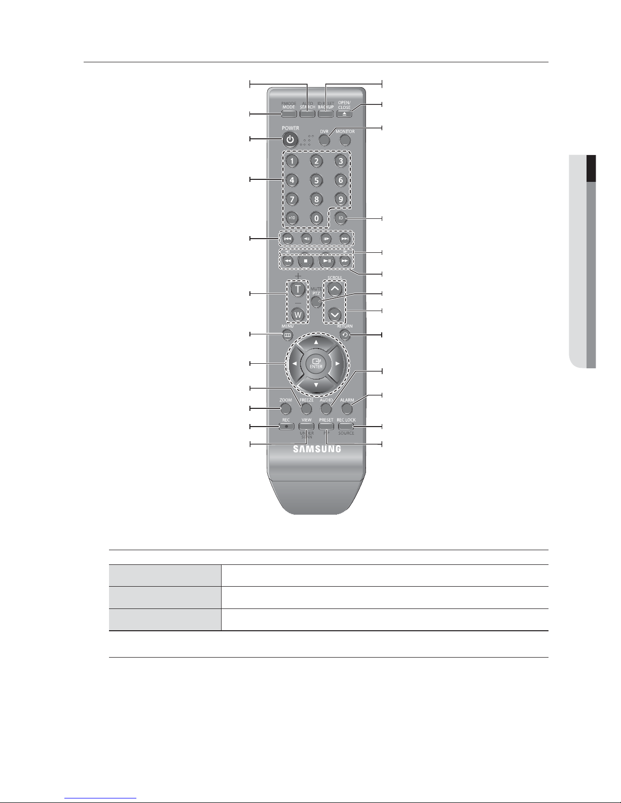
REMOTE CONTROL
Using the numeric buttons
CHANNEL 1–9 Press each button between 1 to 9.
CHANNEL 10 Press the [+10] button first, then press the 0 button again within 3 seconds.
CHANNEL 11–16 Press the [+10] button first, then press any number between 1 to 6 within 3 seconds.
Changing the Remote Control ID
Press the ID button of the remote control and check the ID displayed on the DVR screen.
The factory default ID of the remote control is 00.
Enter 2 digits of your selection in order, while pressing the system [ID] button.
When ID input is done, press the system [ID] button again to check the setting.
If you want to change the remote control ID to 08: Press 0 and 8 in order while the system [ID] button is pressed.
Remote control's ID and DVR’s ID should be matched for proper operation. Refer to “Remote Devices”. (Page 48)
1.
2.
3.
M
SEARCH
Displays the search menu.
POWER
Displays the Exit pop up screen.
NUMBER [0~+10]
Used as the numeric input keys, or displays a single
channel.
T/W
Zooms in or out.
BACKUP
Displays the Backup Menu.
MODE
Changes the screen mode.
MENU
Goes to the system menu screen.
Up/Down/Left/Right(▲▼◄ ►)/ENTER
Moves the cursor up/down/left/right, and runs the
Select Menu.
FREEZE
Freezes the screen temporarily.
ZOOM
Runs the digital zoom (x2) function.
VIEW
Runs the View function in the PTZ mode.
OPEN/CLOSE
Opens or closes the CD tray.
DVR
Activates the DVR function.
ID
Sets the ID of the system.
Select 2 digits from 0 ~ 9 while pressing the ID Key.
PTZ
Displays or ends PTZ.
SCROLL ,.
Moves the menu scroll.
RETURN
Returns to the previous screen.
AUDIO
Turns Audio on/off.
ALARM
Cancels the Alarm.
REC LOCK
Selects the recording lock function.
PRESET
Displays the Preset Setup.
REC
Starts or ends the live recording.
Skip Backward (by unit time),
Slow Rewind, Slow Forward,
Skip Forward (by unit time)
Move Frame
While paused, moves to the previous/next frame.
FR, STOP, PLAY/PAUSE, FF
Page 14
14_ installation
Please take note of the followings before using this product.
Do not use the product outdoor.
Do not spill water or liquid in the connection part of the product.
Do not impose the system to excessive shock or force.
Do not pull out the power plug forcefully.
Do not disassemble the product on your own.
Do not exceed the rated input/output range.
Use a certified power cord only.
For the product with an input ground, use a grounded power plug.
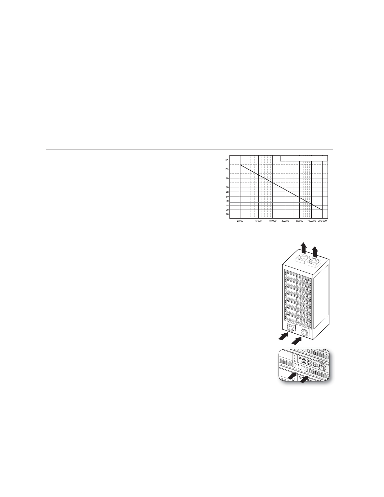
CHECKING THE INSTALLATION ENVIRONMENT
Samsung Digital Video Recorder (“DVR” hereinafter) is a
state-of-art security device, and contains mass storage hard
disk(s) and critical circuits inside.
When the temperature rises inside the product, the product
may breakdown and the product life be shortened. Please
pay attention to the following recommendations before
installation.
The followings are the recommendations when Samsung DVR is installed on a rack.
Please ensure that the rack inside is not sealed.
Please ensure the air is circulated through the inlet/outlet as shown in the picture.
If the DVR or other devices on a rack is to be stacked as in the picture, provide a
suitable space or install a ventilating opening for air circulation.
For natural air convection, place the inlet at the bottom of the rack and the outlet on
top.
It is strongly recommended that a fan motor is installed at the inlet and the outlet for air
circulation. (Please fit a filter at the inlet to screen dust or foreign substances.)
Please maintain the temperature inside the rack or surrounding areas between 0°C ~
40°C (32°F ~ 104°F) as shown in the figure 1.
Rack Mount Instructions - The following or similar rack-mount instructions are
included with the installation instructions :
A) Elevated Operating Ambient - If installed in a closed or multi-unit rack assembly, the
operating ambient temperature of the rack environment may be greater than room
ambient. Therefore, consideration should be given to installing the equipment in an
environment compatible with the maximum ambient temperature (Tma) specified by
the manufacturer.
B) Reduced Air Flow - Installation of the equipment in a rack should be such that the
amount of air flow required for safe operation of the equipment is not compromised.
C) Mechanical Loading - Mounting of the equipment in the rack should be such that a hazardous condition is
not achieved due to uneven mechanical loading.
D) Circuit Overloading - Consideration should be given to the connection of the equipment to the supply circuit
and the effect that overloading of the circuits might have on overcurrent protection and supply wiring.
Appropriate consideration of equipment nameplate ratings should be used when addressing this concern.
E) Reliable Earthing - Reliable earthing of rack-mounted equipment should be maintained. Particular attention should
be given to supply connections other than direct connections to the branch circuit (e.g. use of power strips).
•
•
•
•
•
•
•
•
1.
2.
3.
4.
5.
6.
One Year: 24HR X 365 DAY =8,760 HR
Temperature
Unit: ºC
Life (Unit: HOURS)
[Figure 1]
[Figure 2]
installation
Page 15
English _15
INSTALLATION
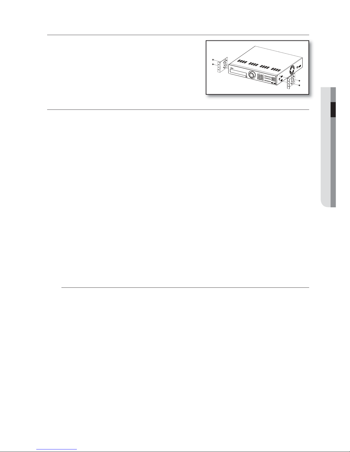
RACK INSTALLATION
Install the Bracket-Rack as shown in the figure, and then fasten the
screws on both sides (2 screws on each side).
Fix the screws not to be loosened by vibrations.
HDD ADDITION
You can install additional HDDs.
Make sure to unplug the power cord from the wall outlet to prevent possible electric shock, injury or product
damage.
Please consult your provider for further information on HDD installation since improper installation or settings may
damage the product.
Number of HDDs supported : Default 1 HDD + Up to 4 HDDs added
Make sure to unplug the power cord from the wall outlet before proceeding with the installation.
By factory default, the unit is equipped with one HDD.
Cautions for data loss (HDD care)
Please pay attention so that the data inside the HDD is not damaged.
Before adding a HDD, please check the compatibility with this DVR product.
HDD is vulnerable to malfunction due to its sensitive nature especially against shock when operating.
Please ensure that the HDD is free from such shock.
We are not liable for any damage to the HDD incurred by user’s carelessness or miss use..
Cases might cause damage to HDD or recorded data
To minimize the risk of data loss from a damaged HDD, please backup data as often as possible.
Data may be lost due to external impacts during disassembly or installation of the DVR.
HDD may be damaged if the DVR is suddenly stopped by a power cut or power off during operation.
HDD or files stored inside may be damaged if the main body is moved or impacted during the HDD operation.
Cautions when adding a HDD
When adding a HDD, ensure that the cable does not get caught or the insulation does not come off.
Pay attention so as not to lose the disassembly screws or accessories.
If the screws or accessories are not put together correctly, the product may breakdown or not operate properly.
Please check the HDD compatibility before adding a HDD.
Please contact your nearest dealer to obtain the list of compatible devices.
J
1.
2.
3.
Page 16
16_ installation
installation
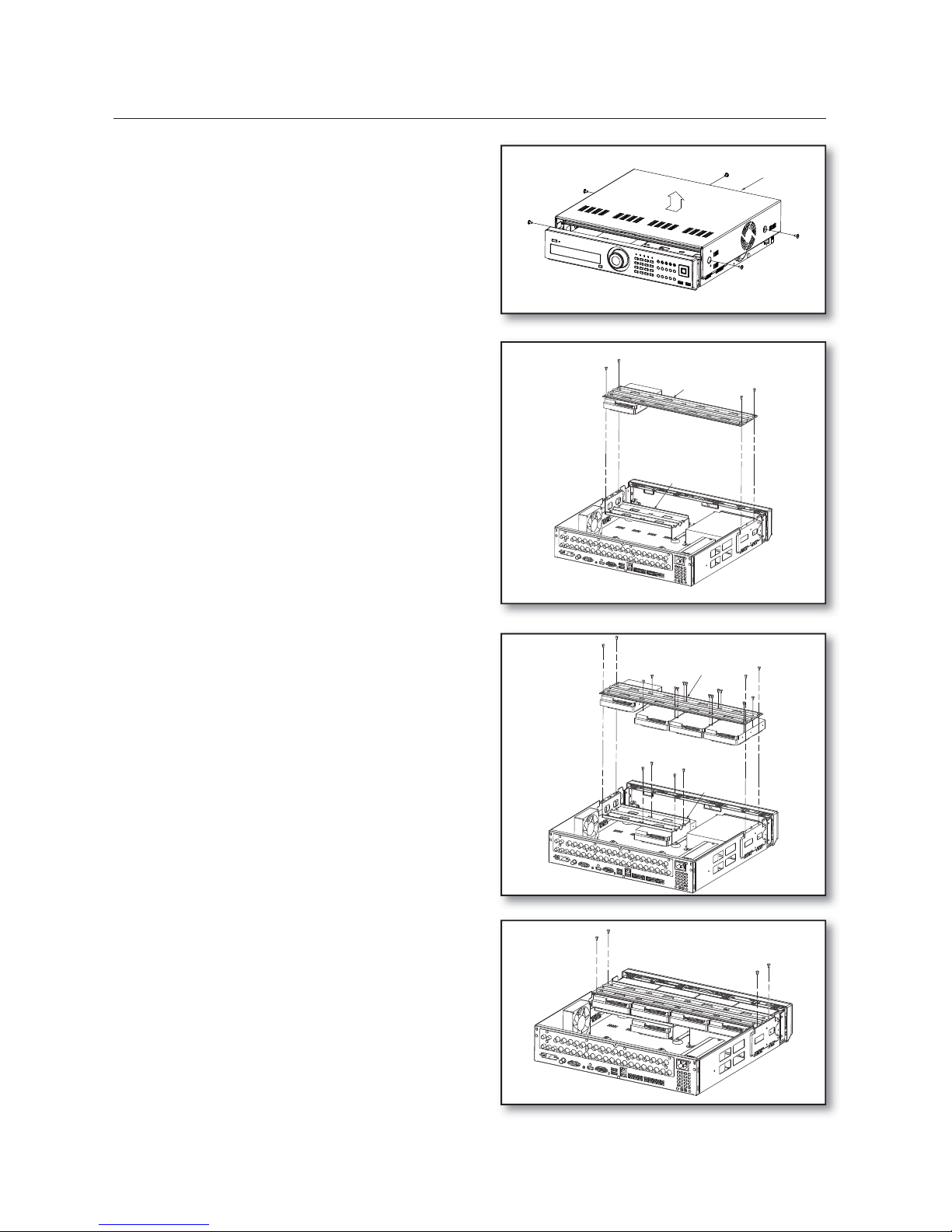
First, loosen the screws on both sides and remove
the cover.
Disconnect the power and HDD Signal cable from
the existing HDDs, then loosen the screws (x4) in
the left/right and upper sides and remove the upper
brackets.
Install a HDD (x1) on the lower bracket and fix it
with screws.
Firmly secure the screw so that it does not become
loose from vibration.
Install HDDs (x3) on the upper bracket and fix them
with screws.
When the installation of additional HDDs is done,
insert the lower and upper brackets into the DVR
and fix them with the provided screws.
1.
2.
3.
4.
5.
Upper Bracket
Lower Bracket
Cover
Upper Bracket
Lower
Bracket
Page 17
English _17
INSTALLATION
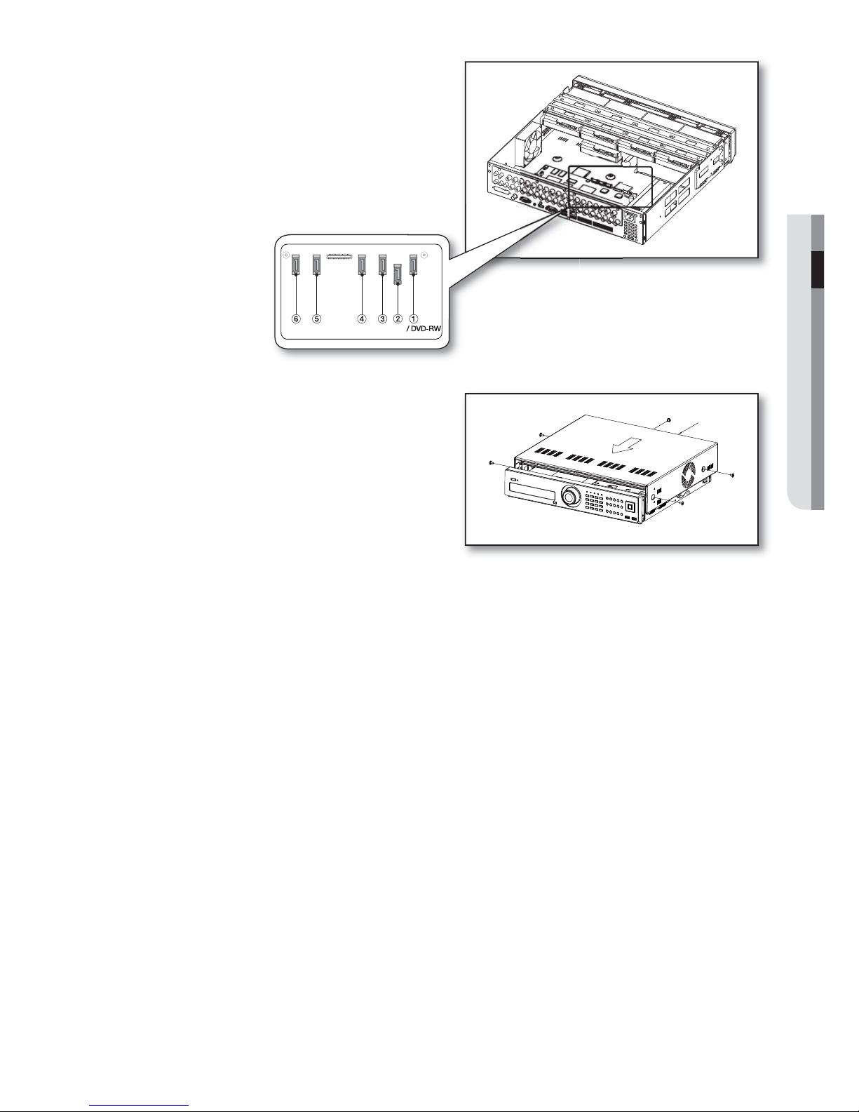
When the installation of additional HDDs is done,
connect the power cable and connect the HDD
data cables (SATA Cable) to connectors c ~ h on
the main board.
Note that the number of a HDD data calbe is nothing to
do with operation of the HDD. Just make arrangements
of the connectors considering the length of each
connector.
Check if the connectors are properly connected
and there is no problem with wiring, and close the
cover and fix it with screws.
6.
7.
Cover
Page 18
18_ connecting with other device
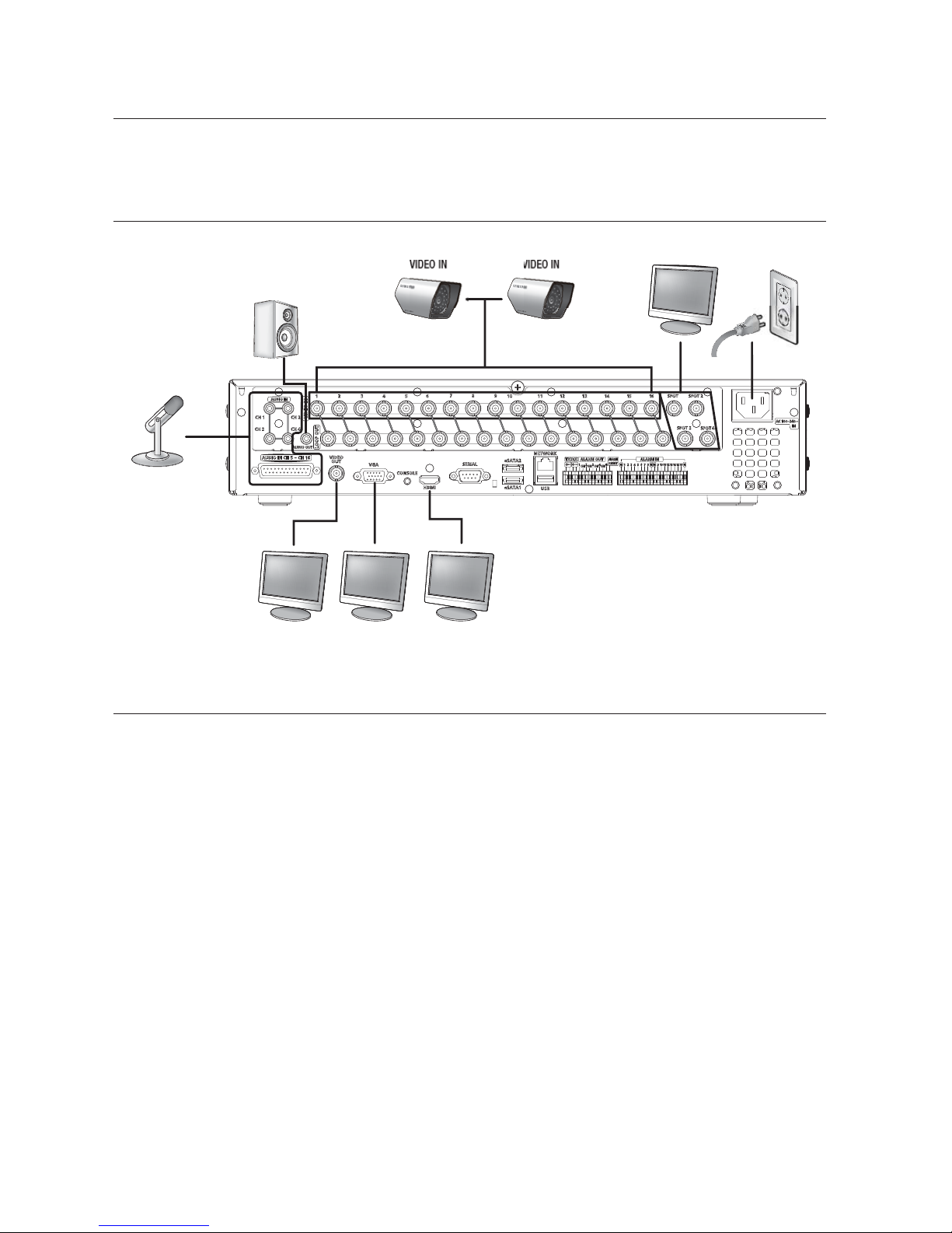
The following figures are based on Model SRD-1670DC.
CONNECTING THE VIDEO, AUDIO, AND MONITOR
CONNECTING THE USB
There are two USB ports at the front and one at the back of the product.
You can connect a USB HDD, USB CD/DVD player, USB memory or mouse to the USB port.
If a USB HDD is connected to the system, recognition and settings are available in “Menu > Setting the Device >
Storage Device”. (Page 46)
This product supports hot-plugging, which connects/removes the USB device during the system operation.
If you use the USB device for Backup purposes, format it with FAT32 on PC if it is not formatted on the DVR.
M
1.
2.
3.
4.
J
connecting with other device
VIDEO IN
AUDIO IN
SPOT AC 100-240V~IN
VIDEO OUT
(VGA)
VIDEO OUT
(composite)
AUDIO OUT
HDMI
VIDEO IN
Page 19
English _19
CONNECTING WITH OTHER DEVICE
CONNECTING EXTERNAL SATA HDD
SRD-830DC/1610DC/1630DC does not support a port for SATA connection.
There are two external SATA ports on the rear side of the product.
If an external SATA HDD is connected to the system, recognition and settings are available in “Menu > Device >
Storage Device”.
The DVR supports Hot Plug function to allow connection and disconnection of SATA HDD devices while the
system is in use.
Only one SATA HDD can be connected to an external SATA port.
Use a cable shorter than 1 m for the external SATA HDD connections.
CONNECTING POS DEVICE
You can connect a POS device to the RS-232C port on the product’s rear side when you connect it directly with
a RS-232C cable.
Connection setup for the RS-232C port is available in “Menu > Device > POS Devices”, press the
<POS Device Setup> button and set <Baudrate, Parity, Data, Stop bit and Transfer Type>. (Page 49)
CONNECTING THE ALARM INPUT/OUTPUT
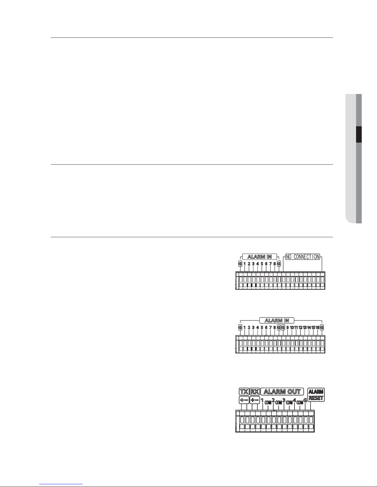
The Alarm In/Out port at the back is composed of the following.
Alarm In Port for SRD-830DC/850DC/870DC
Alarm In Port for SRD-1610DC/1630DC/1650DC/1670DC
Alarm Out Port
M
1.
2.
3.
J
1.
2.
1.
2.
3.
Page 20
20_ connecting with other device
connecting with other device
ALARM IN 1 ~ 8 (SRD-830DC/850DC/870DC) : Alarm Input Port
ALARM IN 1 ~ 16 (SRD-
1610DC/1630DC/1650DC/1670DC) : Alarm Input Port
ALARM RESET : On receiving an Alarm Reset signal, the system cancels the current Alarm Input and resumes
sensing.
ALARM OUT 1 ~ 4 : Alarm Output Port
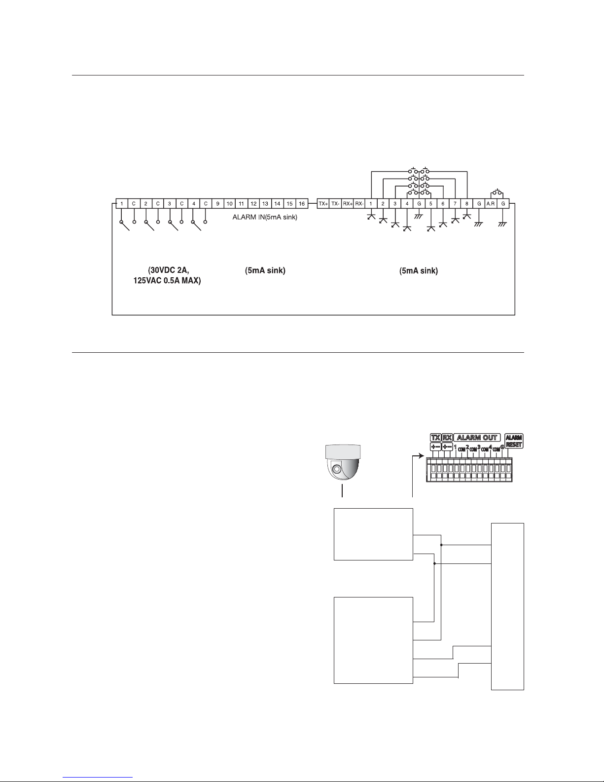
CONNECTING THE RS-485 DEVICE
Connect the RS-485 device through the back port.
You can connect and control the PTZ camera which supports the RS-485 communication.
Transfer Type : You may select either Half Duplex or
Full Duplex as the data transfer type.
Baud Rate : Supported Baud rates are 600/1200/
2400/4800/9600/19200/38400.
Check if the RS-485 device is compatible with the
product first.
Pay attention not to change the polarity (+/–) of the
RS-485 device when connecting it.
Depending on camera’s type, connection polarity can be
different.
For further information, refer to the respective PTZ
Camera’s documentation.
Ex : DVR(TX+/–)
¥
SCC-C6433,35(RX+/–)
DVR(TX+/–) ¥ SCC-C6403,07(TX+/–)
•
•
•
•
M
•
•
M
ALARM OUT ALARM IN ALARM IN
PTZ device
Half Duplex Type
Data (–)
Data (+)
Full Duplex Type
Rx(+)
Rx(–)
Tx(–)
Tx(+)
Rear
Tx(–)
Tx(+)
Rx(–)
Rx(+)
Page 21
English _21
CONNECTING WITH OTHER DEVICE
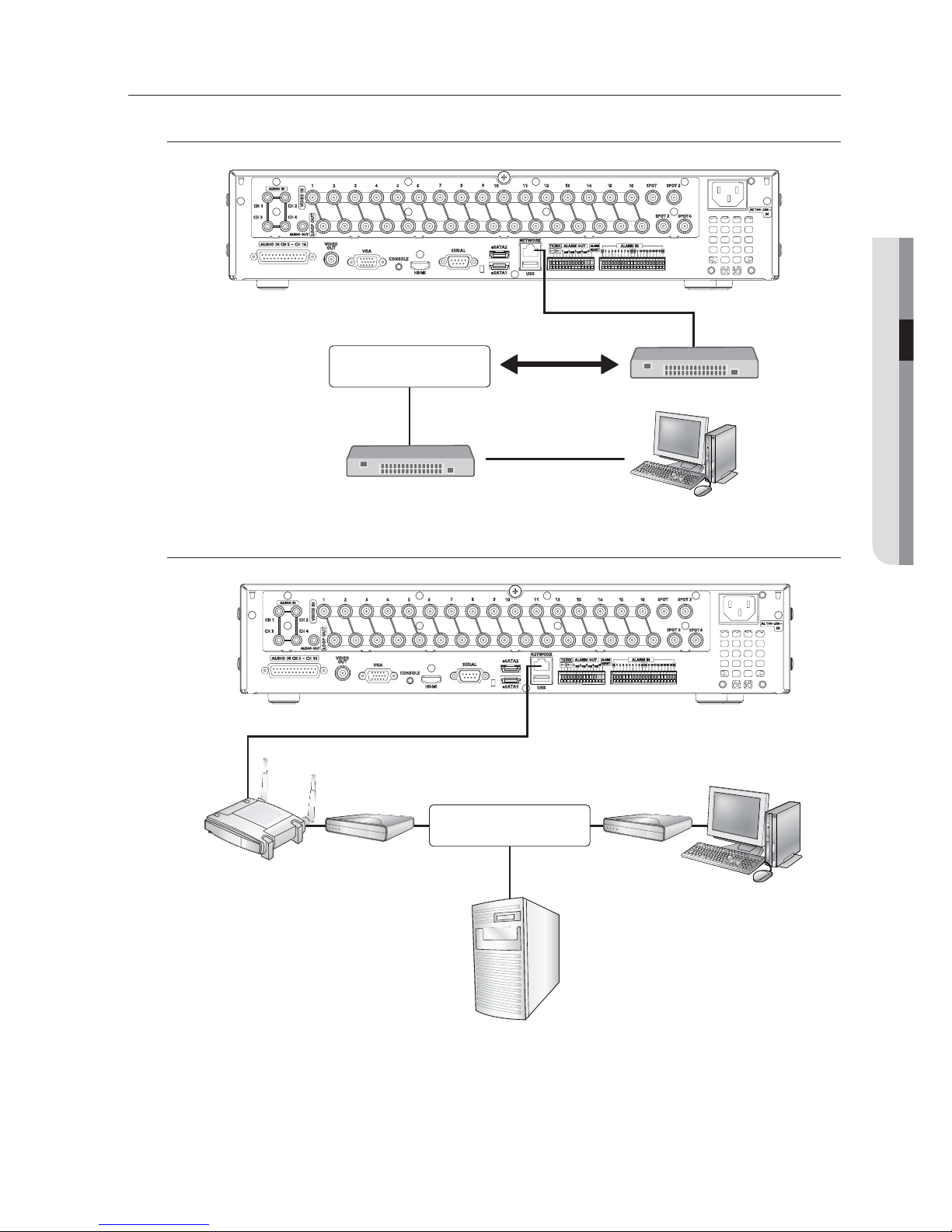
CONNECTING THE NETWORK
Connecting to Internet through Ethernet (10/100/1000BaseT)
Connecting to the Internet using the router
Router
xDSL or Cable
Modem
xDSL or Cable
Modem
External Remote
PC
DDNS Server
(Data Center)
INTERNET
Windows
Network Viewer
Back Bone
Hub/Switcher
Hub/Switcher
RJ-45 Ethernet Cable
(Direct Cable)
INTERNET
Page 22
22_ connecting with other device
connecting with other device
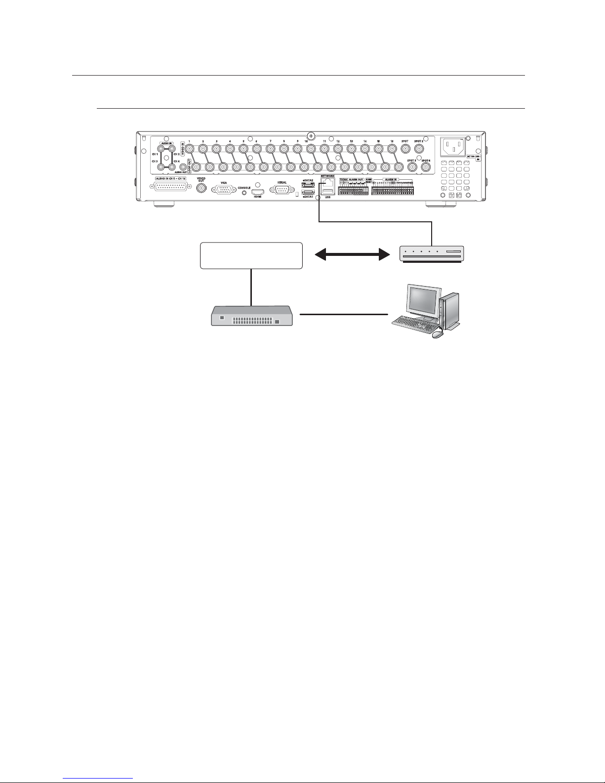
Connecting to Internet through ADSL
Hub/Switcher
Phone(ADSL) Line
ADSL MODEM
RJ-45 Ethernet Cable
(Direct Cable)
Windows
Network Viewer
INTERNET
Page 23
English _23
LIVE
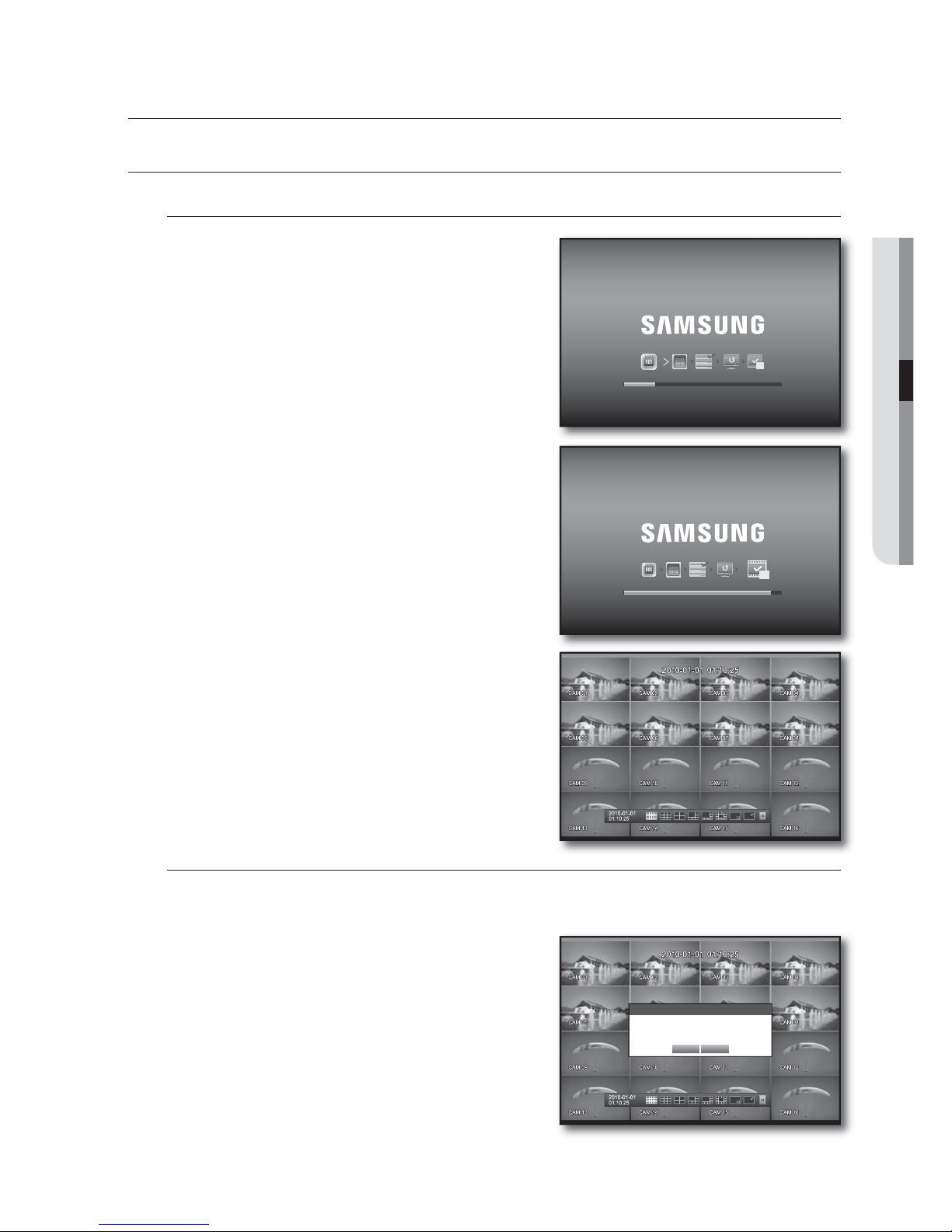
GETTING STARTED
Starting the system
Connect the power cable of the DVR to the wall outlet.
Press the Power button on the front panel.
You will see the initialization screen.
The initialization process will last about 1 minute.
If a new HDD is installed, the initialization process may take
longer.
The live screen appears with a beep.
Shutting Down the System
You can shut down the system only if you have logged in to the DVR.
You require permission to shut down the system if you are not logged in as admin.
Press the [POWER] button on the remote control or the
front panel, or right-click to display the context sensitive
menu and select <Shutdown>.
The “Shutdown” confirmation window appears.
Use the arrow keys on the remote control or the front panel
to move to <OK> and press the [ENTER] button or click
<OK>.
The system will shut down.
For the permission management, refer to “Permission
Management > Setting Permissions”. (Page 39)
1.
2.
3.
4.
1.
2.
3.
M
live
REC
REC
Shutdown
Are you sure to shutdown?
OK Cancel
Page 24
24_ live
live
Login
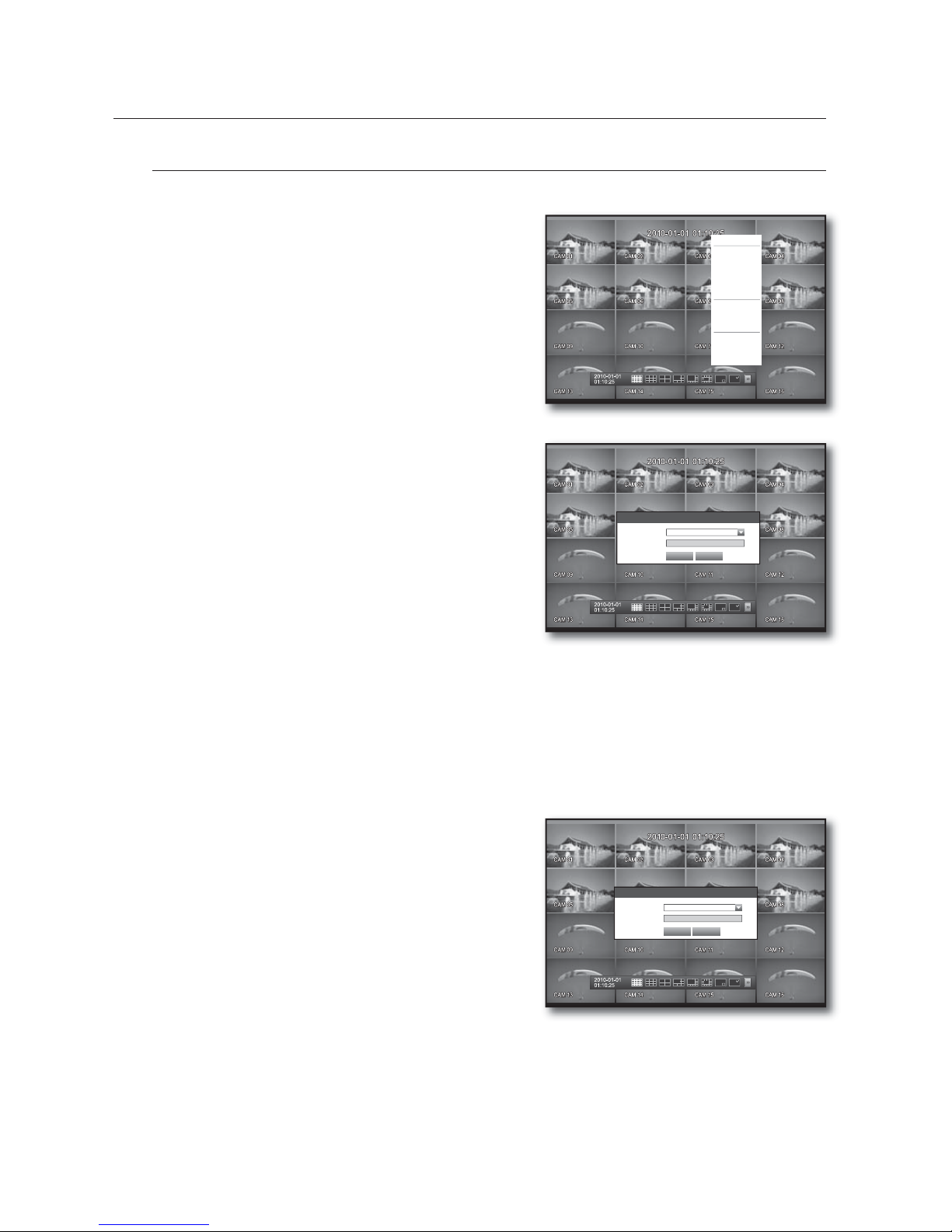
To access a DVR or restricted menu, you should have logged in to the DVR.
In live mode, right-click any area of the screen.
You will see the context sensitive menu as in the right
figure.
Click <Login>.
The login dialog appears.
You can also see the login dialog to access a desired menu
by pressing the [MENU] button on the remote control or
the front panel.
The login dialog will also appear if you press a menu button on
the remote control or the front panel of the DVR when the
corresponding menu requires logging in.
By default, initial ID and password are set to “admin”, and
“4321”.
For the restricted permission, refer to “Permission Management > Setting Permissions”. (Page
39)
Locking All Buttons
This will restrict access to all buttons available in the DVR.
In Live mode, press buttons in the order of [STOP]
l
[FREEZE]l[STOP]l[FREEZE]l[MENU].
All buttons will be locked.
In the lock condition, press any button to display a dialog
where you are prompted to enter the password for
unlocking the buttons.
The button lock will be released if you enter the admin
password.
1.
2.
M
1.
2.
Login
x
ID admin
x
Password
OK Cancel
Scene Mode
f
Audio Off
Freeze
Stop Alarm
Record
Play
Search
Backup
Main Menu
Shutdown
Hide Launcher
Login
Key Lock Password
x
ID admin
x
Password
OK Cancel
Page 25
English _25
LIVE
LIVE SCREEN CONFIGURATION
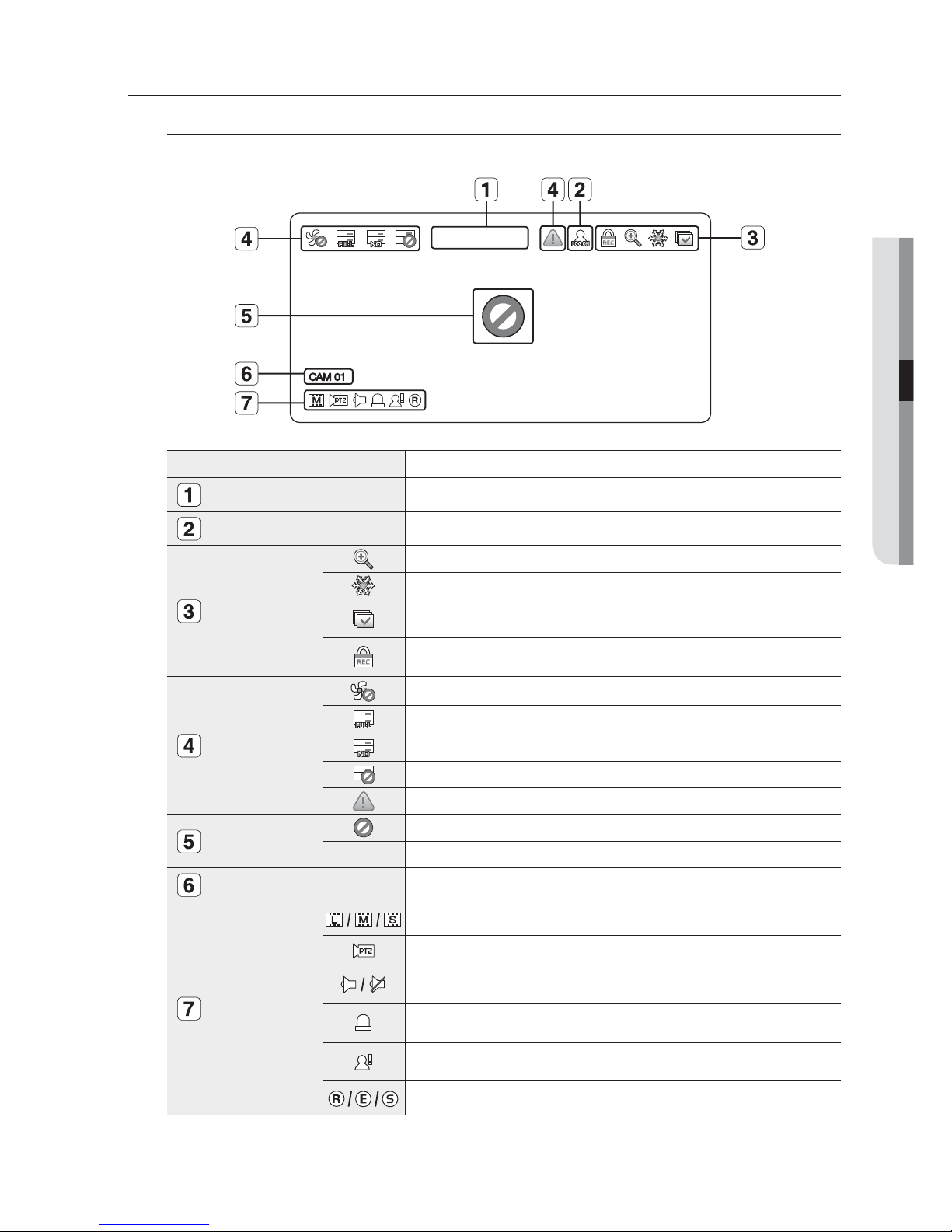
Icons on the Live Screen
You can check the status or operation of the DVR with the icons on the live screen.
Name Description
Current Date, Time
Displays the current time and date.
Login Information
When you are logged in, the “LOG ON” icon will be displayed.
Screen Mode
Displayed if the zoom function is activated.
Displayed if you press the Pause button.
Displayed in Auto Sequence mode where all channels are switched at the
specific time interval.
Displayed if the recording is in process.
M To cancel the recording, enter the password.
System Operation
Displayed if there is a problem with the cooling fan.
Displayed if the HDD is full and the DVR has an insufficient space to record.
Displayed if no HDD is installed or the existing HDD should be replaced.
Displayed if the HDD needs a technical examination.
Displayed if a new firmware is found from the network.
Video Input Status
Displayed if no input is entered in the condition that the camera is set to <ON>.
Nothing will be displayed on the screen if the camera is set to <OFF>.
Camera Name/ Channel
Displays the camera name and the changed channel, if any.
Camera Operation
Displays the resolution of the recording screen. (Page 54)
Displayed in PTZ setting, and highlighted yellow if PTZ is in operation.
Displays AUDIO ON/MUTE.
Not displayed in video mode if deactivated.
If the sensor is set to <ON>, the input signal will be displayed on the screen of
the connected channel.
Displayed if a motion detected in the condition that the motion detection is set to
<ON>.
Displays the current record mode from Record/Event/Schedule.
2010-01-01 00:00:01
CAM 01
Page 26
26_ live
live
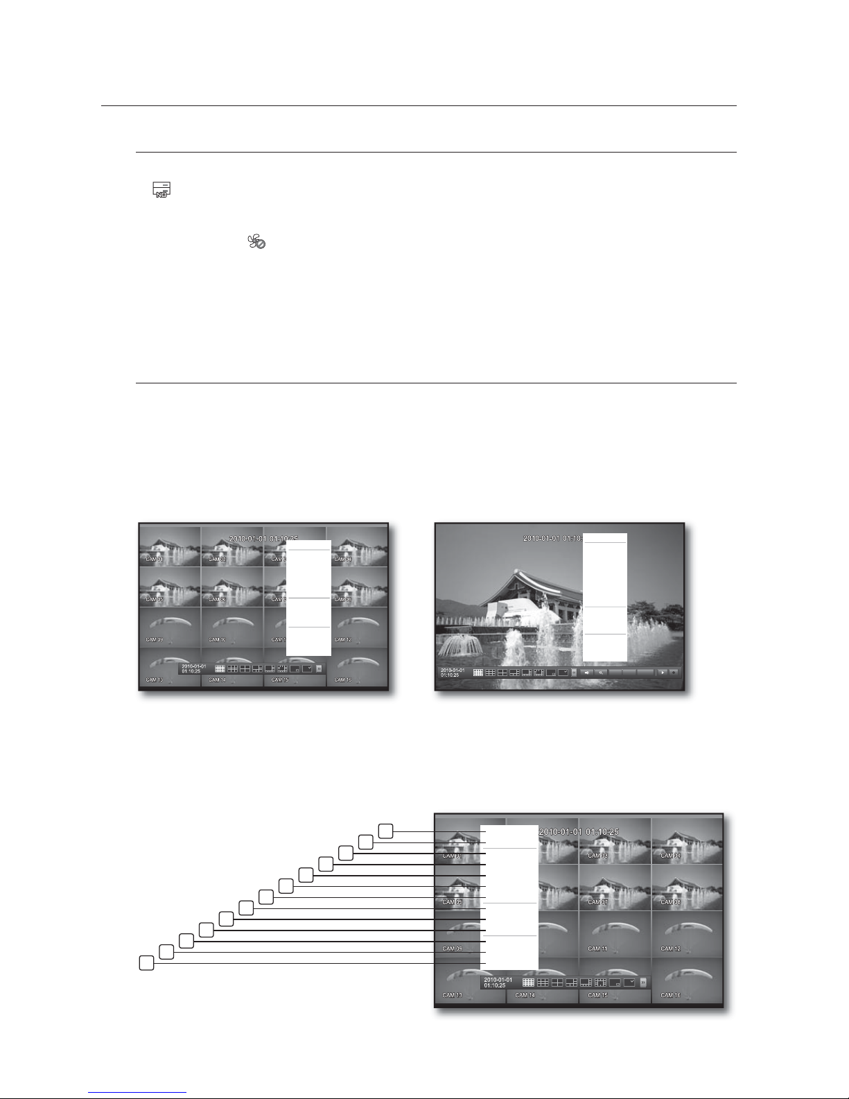
Error Information
If you turn on the system when the internal HDD is not connected or an error occurs, the “HDD FAIL” icon
(
) will be displayed on the top left corner. In this case, make sure you contact the service center for
assistance as this may cause a failure of recording, playback or backup.
If the cooling fan does not work properly or has a problem, the <Fan Information> window will appear and
the fan error icon (
) will be displayed on the top left corner. In this case, check to see if the internal fan
works.
As a fan error can shorten the product life, make sure you contact the service center for assistance.
If you see the fan error icon or No HDD, HDD FAIL icons on the screen, contact the service center for more details.
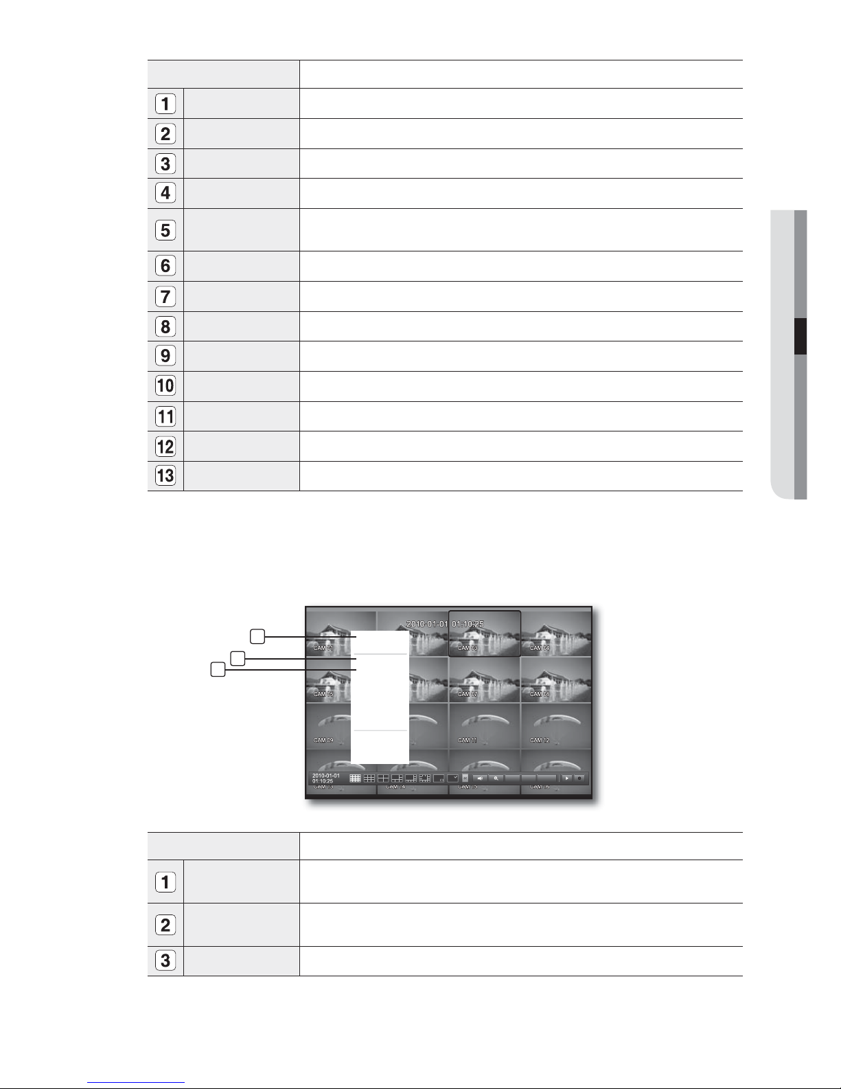
Live Screen Menu
In addition to the buttons on the front panel or the remote control, you can access a desired menu by rightclicking the mouse any area in live mode.
The context sensitive menu that appears by right-clicking the screen may differ, depending on the login/
logout, screen split mode and DVD operation mode.
Menu items of Search, Record, Backup, Shutdown and PTZ can be deactivated, depending on the user permission.
Split Mode Menu
The context sensitive menu in split mode differs, depending on the login/logout status.
•
•
M
M
Scene Mode
f
Audio Off
Freeze
Stop Alarm
Record
Play
Search
Backup
Main Menu
Shutdown
Hide Launcher
Login
< Split Mode Menu >
< Single Mode Menu >
PTZ Alarm Freeze
Scene Mode
f
PTZ Control
ZOOM
Audio
f
Freeze
Stop Alarm
Record
Play
Search
Backup
Main Menu
Shutdown
Hide Launcher
Login
Scene Mode
f
Spot Out
f
Audio Off
Freeze
Stop Alarm
Record
Play
Search
Backup
Main Menu
Shutdown
Hide Launcher
Logout
2
13
12
11
10
9
8
7
6
5
4
3
1
Page 27
English _27
LIVE
Menu Description
Scene Mode Refer to “Live Mode”. (Page 29)
Spot Out Refer to “Spot Out”. (Page 31)
Audio On/Off Refer to “Audio ON/OFF”. (Page 32)
Freeze Refer to “Freeze”. (Page 32)
Stop Alarm
Stops the alarm output and the event monitoring. Refer to “Event Monitoring”.
(Page
33)
Record/Stop Starts/stops the standard recording.
Play Plays the search result (data). Refer to “Search & Play > Play”. (Page 71)
Search Refer to “Search & Play > Search”. (Page 68)
Backup Refer to “Using the DVR > Setting the Backup”. (Page 58)
Main Menu Accesses the main menu. Refer to the Using the DVR section. (Page 34)
Shutdown
Turns down the DVR.
Show/Hide Launcher
Shows or hides the launcher. Refer to “View the Launcher Menu”. (Page 28)
Login/Logout You can log in or out.
Single Mode Menu
The single mode menu is available only in Single Mode.
The context sensitive menu for the One Channel mode, in Split mode is different from that of the Single mode.
Menu Description
Full Screen
Select and click a desired channel in Split mode to switch to the full screen of the selected
channel.
PTZ Control
Accesses the PTZ Control menu. The PTZ menu is activated only in One-Channel Live mode.
(Page 66)
ZOOM Enlarges the selected image. (Page 32)
PTZ Alarm Freeze
Full Screen
Spot Out
f
PTZ Control
ZOOM
Audio
f
Freeze
Stop Alarm
Record
Play
Shutdown
Hide Launcher
Logout
2
3
1
Page 28
28_ live
live
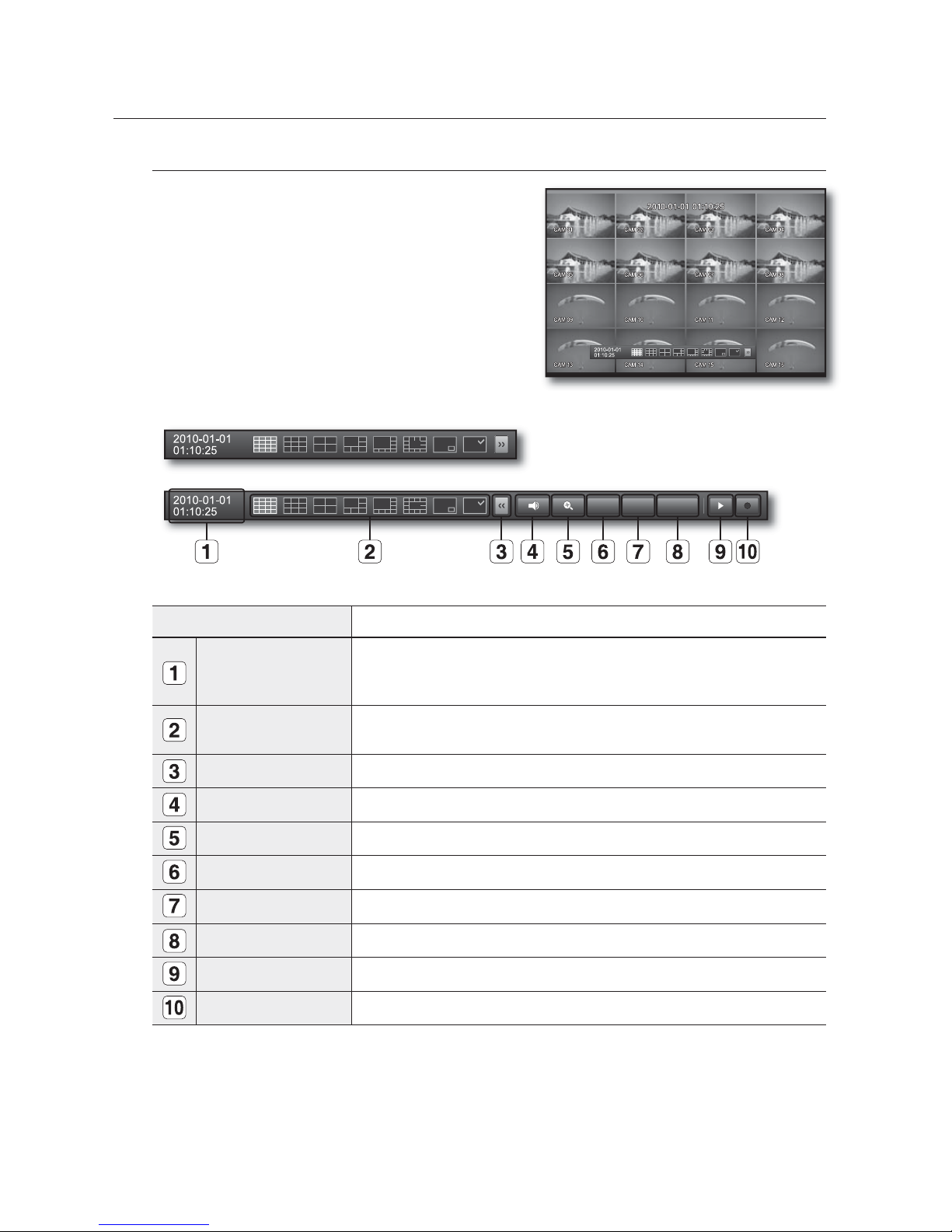
View the Launcher Menu
The Launcher menu appears on the bottom of the live screen.
In Live mode, right-click to display the context menu and
select <Show Launcher>.
Move the cursor to the bottom and click a desired item in
the Launcher menu.
If no input is entered for 10 seconds, the menu will disappear.
The Launcher menu can be accessed only by using the mouse.
SRD-830DC/850DC/870DC do not support the 16-split
screen mode.
Menu Description
Date/Time
Displays the current time and date.
The indication of AM/PM is displayed if you set 12 hours for the time format in
“System > Date/Time/Language > Time”. (Page
34)
Screen Mode
Displays in the sequence of 16-, 9-, 4-, 6-, 8-, 13-split, PIP and Auto Sequence.
The current mode is highlighted in white.
Menu Expansion Button Click to display the hidden menu to the right.
Audio Turns ON/OFF the sound of the selected channel.
Zoom Enlarges the selected area. This is available only in Single Live mode.
PTZ Runs the PTZ Control launcher. This is available only in Single Live mode.
Alarm Stops the alarm if it's activated.
Freeze Freezes the Live screen temporarily.
Play Enters Play mode if a file to play exist, and if not, enters Search mode.
Record Start/End recording the Live screen.
1.
2.
M
PTZ
Alarm Freeze
Page 29
English _29
LIVE
LIVE MODE
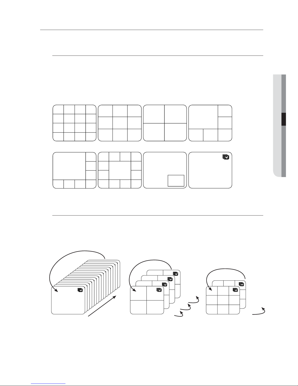
SRD-1610DC/1630DC/1650DC/1670DC display Live images from 16 channels in a total of 8 layout of split screens.
Switching the screen mode
To switch the split mode, select a screen mode in the launcher menu, or right-click to select a screen mode in
the context menu.
Press the [MODE] button on the front panel or the remote control to switch the mode in the sequence of the
launcher menu items.
SRD-830DC/850DC/870DC do not support the 16-split screen mode.
Switching the split mode
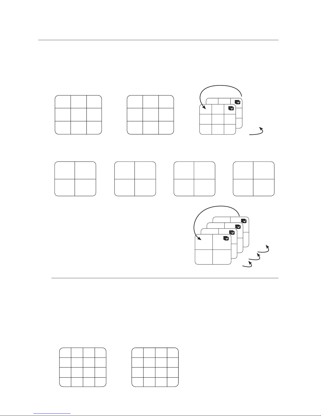
SRD-1610DC/1630DC/1650DC/1670DC display 16 Live images in the sequence of Single, 4-split and 9-split
modes.
Auto Sequence
In Single mode, If you have set <SEQ-Dwell Time> in “Setting the Device > Camera”, Auto Sequence will be
conducted at the set interval. (Page 44)
In a split mode, If you have set <Multi CH SEQ Time> in “Setting the Device > Monitor”, Auto Sequence will be
conducted at the set interval. (Page
50)
M
M
CH1
CH1
CH1
CH2
CH3
CH2
CH3 CH4
CH2 CH3
CH4 CH5 CH6
CH4 CH5 CH6
CH7 CH8 CH9
CH1 CH2 CH3 CH4
CH5 CH6 CH7 CH8
CH9 CH10 CH11 CH12
CH13 CH14 CH15 CH16
CH1
CH2
CH1
CH2
CH6
CH8
CH10 CH11 CH12 CH13
CH3 CH4 CH5
CH7
CH9
CH1
CH5 CH6 CH7 CH8
CH2
CH3
CH4
CH1
16-split mode 9-split mode 4-split mode 6-split mode
8-split mode 13-split mode PIP
Auto Sequence
16
CH1
CH1
CH1
CH1
CH1
CH1
CH1
CH1
CH1
CH1
CH1
CH1
CH1
CH1
CH1
CH1
1
Single mode
CH1 CH2
CH3 CH4
CH1 CH2
CH3 CH4
CH1 CH2
CH3 CH4
CH1 CH2
CH3 CH4
13-16
9-12
5-8
1-4
4-split mode
CH1 CH2 CH3
CH4 CH5 CH6
CH7 CH8 CH9
CH1 CH2 CH3
CH4 CH5 CH6
CH7 CH8 CH9
10-16
1-9
9-split mode
Page 30
30_ live
live
Manual Switching
Press the left/right button on the front panel or the remote control, or click the arrow <◄/►> key to move to
the next split mode.
If pressing the right [
►
] button in 9-split mode :
9-split (CH 1~9) mode p 9-split (CH 10~16) mode p Auto Sequence
If pressing the right [
►
] button in 4-split mode :
Channel (CH 1~4) p Channel (CH 5~8) p Channel (CH 9~12) p Channel (CH 13~16) p Auto Sequence
Channel Setting
You can display the channel in a desired area of a split screen.
Place the cursor over the camera name of each channel to display the <
▼
> key to the right on the screen.
Click a camera name to display a channel list where you can select a different channel.
Select a desired channel and click it.
The current channel will be switched to the selected one.
Use the cursor to select a channel to move, and drag and drop it to a desired channel; this can also
change the channel position.
Ex : if switching CH 1 to CH 7
•
•
1.
2.
3.
CH1 CH2
CH3 CH4
CH5 CH6
CH7 CH8
CH9 CH10
CH11 CH12
CH13 CH14
CH15 CH16
CH1 CH2
CH3 CH4
CH1 CH2
CH3 CH4
CH1 CH2
CH3 CH4
CH1 CH2
CH3 CH4
13-16
9-12
5-8
1-4
CH1 CH2 CH3
CH4 CH5 CH6
CH7 CH8 CH9
CH10 CH11 CH12
CH13 CH14 CH15
CH16
CH1 CH2 CH3
CH4 CH5 CH6
CH7 CH8 CH9
CH1 CH2 CH3
CH4 CH5 CH6
CH7 CH8 CH9
10-16
1-9
CH1 CH2 CH3 CH4
CH5 CH6 CH7 CH8
CH9 CH10 CH11 CH12
CH13 CH14 CH15 CH16
CH7 CH2 CH3 CH4
CH5 CH6 CH1 CH8
CH9 CH10 CH11 CH12
CH13 CH14 CH15 CH16
Page 31
English _31
LIVE
Switching to Single Mode
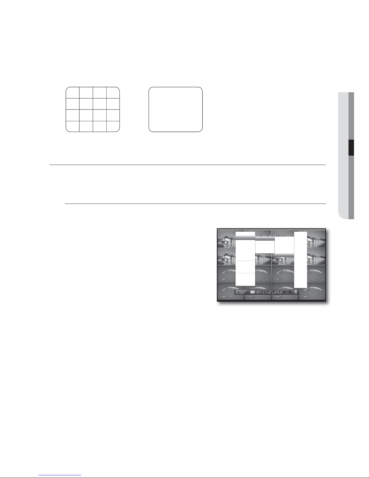
When in split mode, select and double-click a desired channel to switch to its Single mode.
Press the number corresponding to a desired channel on the front panel or the remote control to switch to its
Single mode.
Refer to “Remote Control > Using the numeric buttons”. (Page 13)
Ex : If double-clicking CH 3 or pressing the number “3” on the remote control or the front panel.
SPOT OUT
The Spot Out monitoring is independent of the Live mode, which monitors a specific channel through the Spot Out
port.
Selecting a Spot Out mode
If an event occurs such as sensor, motion or alarm from the Spot Out port in connection with a monitor, you
can select a output screen mode.
In Live mode, right-click any area on the screen.
The Live menu appears.
Click Spot Out.
The split screen appears according to the Spot Out source.
(Page
51)
Spot Out 1 : Supports 16-, 9-, 4-split, Auto Sequence and Single
modes.
Spot Out 2, 3, 4 : Supports 4-split, Auto Sequence and Single
modes.
The number of Spot Out terminals differs according to the model.
For the Spot Out port of a model, refer to “Part Names and
Functions (Rear)”. (Page 10)
1.
2.
CH1 CH2 CH3 CH4
CH5 CH6 CH7 CH8
CH9 CH10 CH11 CH12
CH13 CH14 CH15 CH16
CH3
Spot Out 1
f
Spot Out 2
f
Spot Out 3
f
Spot Out 4
f
Scene Mode
f
Spot Out
f
Audio Off
Freeze
Stop Alarm
Record
Play
Search
Backup
Main Menu
Shutdown
Hide Launcher
Logout
16-split
9-split
4-split
Auto Sequence
Single
f
CH1
CH2
CH3
CH4
CH5
CH6
CH7
CH8
CH9
CH10
CH11
CH12
CH13
CH14
CH15
CH16
< Multichannel Live Menu >
Page 32
32_ live
live
ZOOM
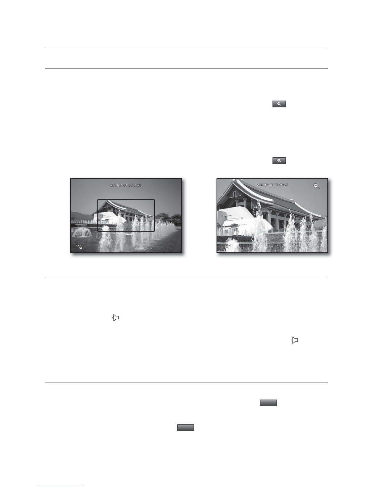
This is available only in Single Live mode. In Single mode, select a desired area and use the Zoom function to
enlarge it twice.
Select <ZOOM> in the right-click menu.
Press the [ZOOM] button on the front panel or the remote control, or simply click <
> in the launcher
menu. The zoom box appears.
Use the direction keys, or drag and drop to specify an area to enlarge.
Press the [ENTER] button, or double-click the selected area to enlarge it twice.
In the enlarged image, use the direction buttons (◄ ►) on the remote control or the front panel to move the
enlarged area.
Press the [ZOOM] button on the front panel or the remote control, or simply click < > in the launcher
menu to release the zoom.
AUDIO ON/OFF
You can turn the sound on/off corresponding to the channel in Live mode.
AUDIO ON/OFF in Single mode
Click the audio icon ( ) on the screen, or press the [AUDIO] button on the front panel or the remote control
to turn it on/off.
Only the channel where <AUDIO> is set to <ON> in “Device > Camera” displays the audio icon ( ) in Live
mode that you can use to turn the sound on/off.
FREEZE
This is available only in Live mode, this pauses playing the Live image temporarily.
Press the [FREEZE] button on the front panel or the remote control, or click <
Freeze
> in the launcher
menu.
The playback of the image is stopped temporarily.
Press the [FREEZE] button again, or click <
Freeze
>.
This will release the freeze.
1.
2.
3.
4.
M
1.
2.
Page 33
English _33
LIVE
EVENT MONITORING
This will display the channel in sync with a specific event (Sensor/Motion/Video Loss) if it occurs.
In “Monitor > Event Display”, set the event monitoring to ON/OFF and specify the event display time. (Page
50)
If multiple events occur simultaneously, the screen will switch to a split mode.
- 2~4 events : 4-split mode
- 5~9 events : 9-split mode
- 10~16 events : 16-split mode
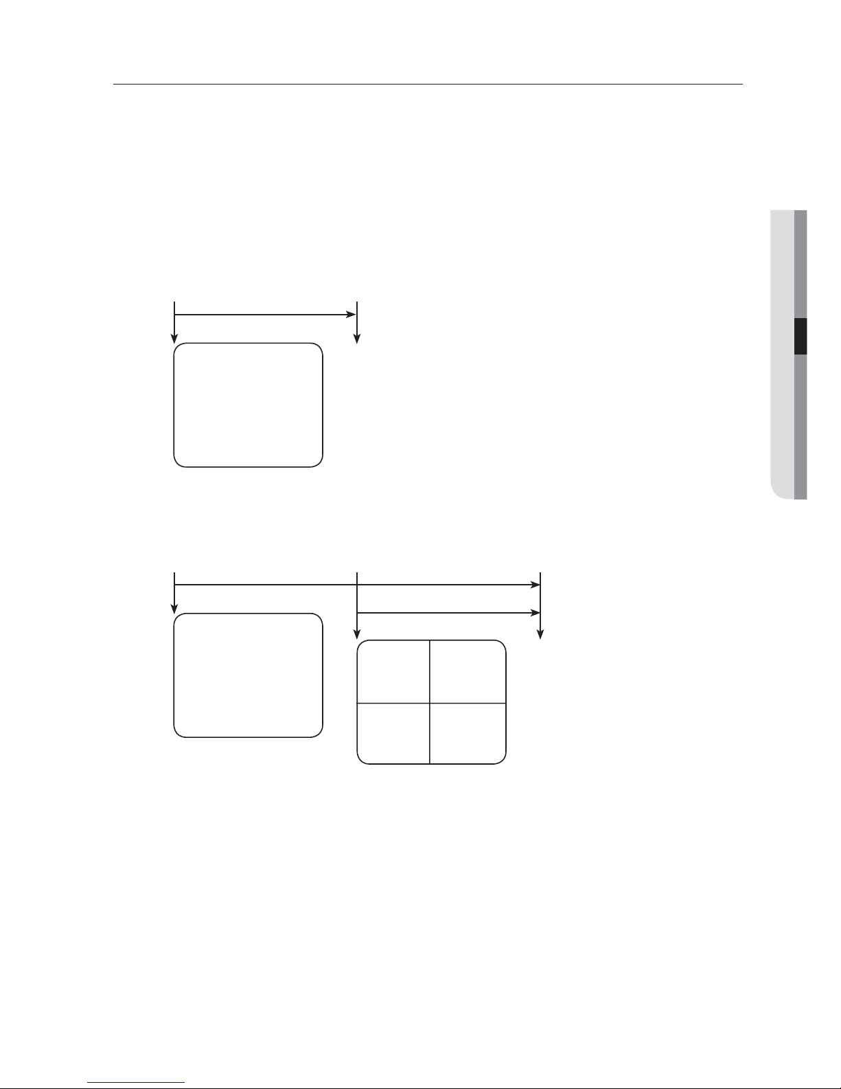
If the second event occurs within the set time of <Event Display>, the first event will last until the second
one is terminated. (Page
50)
Ex : If you set <Event Display> to 5 seconds, and only one event occurs in CH 1.
Ex : If you set <Event Display> to 5 seconds, and the second event occurs in CH 2 within the set time after the first
event occurred in CH 1.
Press the [ALARM] button to reset the alarm settings and to release the event mode.
If an alarm activates in the condition you have set the event record, and pre/post alarm times, the event record will
be performed.
This will also apply to the Spot Out monitor.
•
•
M
CH1
Event occurrence 5 seconds
Stop alarm
CH1 CH2
CH1
Event occurrence 4 seconds 9 seconds
Stop alarm
Page 34
34_ using the DVR
You can setup the system properties, devices, and options for recording, event,
backup and network.
SYSTEM SETUP
You can setup Date/Time/Language, Permission, System Properties and Log.
Date/Time/Language
You can check and setup the current Date/Time and time related properties, as well as the language used for
the interface on the screen.
Setting the Date/Time/Language
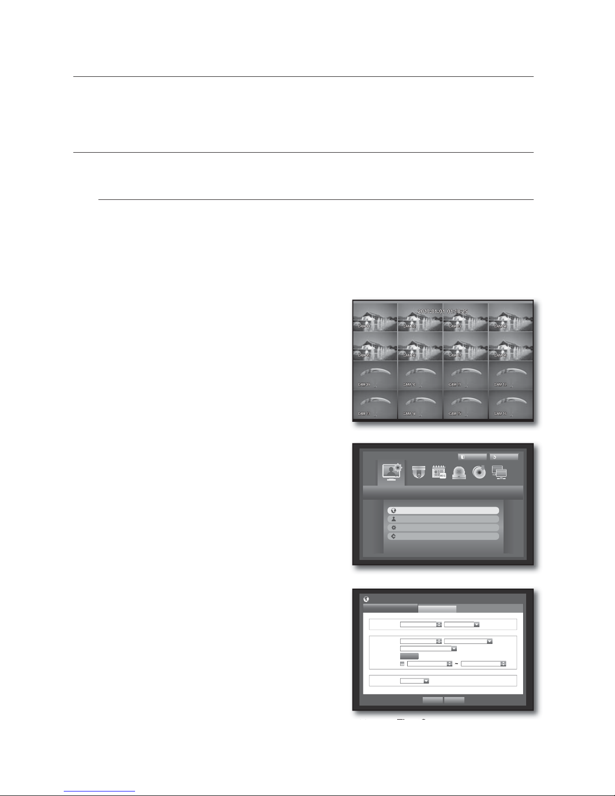
Set the Date/Time/Language
Using the mouse may help make setup easier.
Press the [MENU] button on the remote control or on the
front panel.
If not logged in, it prompts with login window.
Refer to “Login”. (Page 24)
Use the left/right buttons (
◄ ►
) to select the <System>.
System property setup menu is selected.
Use the up/down buttons () to select <Date/Time/
Language> and press the [ENTER] button.
Select <Date/Time/Language>.
A dialog to setup Date, Time and Language.
Use direction buttons (
◄ ►
) to select an item to set
and make your changes.
Date : Sets the date that will appear on the screen.
You can select the date format.
Time : Sets the time and its format that will appear on the
screen.
Select either one from <24 Hours, 12 Hours (AM/PM)>.
Time Zone : Sets the time zone of your area based on the
Greenwich Mean Time (GMT).
GMT (Greenwich Mean Time) is standard World Time and the basis
of world time zone.
Time Sync. : You can set the DVR’s current time
synchronized to a selected <Time Server> regularly if you select to use <Time Server>.
In this case, <Date/Time/Language> setup does not allow time adjustment.
1.
2.
3.
4.
5.
•
•
•
•
VTJOHUIF%73
System
Logout
Exit
Date/Time/Language
Permission Management
System Management
Log Information
Date/Time/Language
Date/Time/Language
Holiday
x
Date 2010-01-01 YYYY-MM-DD
x
Time 08:14:24 24 Hours
x
Time Zone GMT+09:00
x
Time Sync.
Setup
x
DST
Dec First (Sun) 0 Dec First (Sun) 0
x
Language English
OK Cancel
Page 35
English _35
USING THE DVR
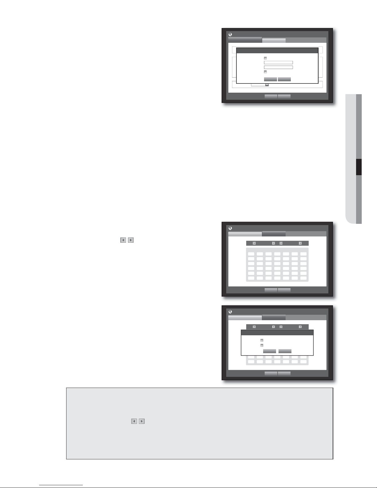
- Time Server : Enter an IP or URL address of the time
server.
- Last Sync Time : Displays the most recent
synchronization time from the selected time server.
- Activate as Server : Set to <Use> to allow the DVR to act
as a Time Server for other DVRs.
DST : Set up Daylight Saving Time with its period to make
the time earlier than the GMT of its time zone by 1 hour
during the set period.
Language : Select your language. Sets the language for the
interface.
English, French, German, Spanish, Italian, Chinese, Russian, Korean, Polish, Japanese, Dutch, Portuguese,
Turkish, Czech, Danish, and Swedish are available.
When the Date/Time/Language setup is done, press <OK>.
You can also use numeric buttons on the remote control or front panel to enter values for Date, Time and other
numeric fields.
Setting Holiday
You can set specific dates to Holidays according to your preferences.
Holidays are applied to <Recording Schedule> and <Alarm Schedule> too.
Using the mouse may help make setup easier.
Use the up/down buttons () in <Date/Time/Language> window to select <Date/Time/Language>, and
press the [ENTER] button.
Select <Holiday>.
A calendar for Holiday setup appears.
Use the left/right <
> buttons to select year or month,
and press the [ENTER] button.
Use direction buttons (
◄ ►
) to select a desired date,
and press the [ENTER] button.
You will see the “Setting Holiday” screen.
Ex : Select January 11th and check on <1/11> only to make
every January 11th a holiday. Check both on <1/11> and <Jan
2nd Mon> to make every January 11th and 2nd Monday of
January holidays.
When the Holiday setup is done, press <OK>.
Using the Calendar
Using the mouse may help make setup easier.
{
Select year and month.
Select the left/right <
> key on the left/right side of year/month and press [ENTER] button to
adjust by 1 year/month.
|
Use direction buttons to select a date and press [ENTER] button.
A date with recorded data to be searched will appear in yellow in the System Log, Event Log, Time Search and Event
Search.
•
•
6.
M
3.
4.
5.
6.
7.
Date/Time/Language
Date/Time/Language
Holiday
x
Date 2010 -01-01 YYYY-MM-DD
x
Time 08:14:24 24 Hours
x
Time Zone GMT+08:00
x
Time Sync.
Setup Not Used
x
DST
Dec First (Sun) 0H Dec First (Sun) 0H
x
Language English
OK Cancel
Time Synchronization Setup
OK Cancel
x
Synchronization Use
x
Time Server 203.248.240.103
x
Last Sync Time Fail
x
Activate as Server Use
OK Cancel
Date/Time/Language
Date/Time/Language
Holiday
2010 Jan
Sun Mon Tue Wed Thu Fri Sat
12
3 45 67 8 9
10 11 12 13 14 15 16
17 18 19 20 21 22 23
24 25 26 27 28 29 30
31
OK Cancel
Date/Time/Language
Date/Time/Language
Holiday
2010 Jan
Sun
Mon Tue Wed Thu Fri Sat
12
3 45 67 8 9
10 11 12 13 14 15 16
17 18 19 20 21 22 23
24 25 26 27 28 29 30
31
Setting Holiday
OK Cancel
1 / 11
Jan 2nd Mon
Page 36
36_ using the DVR
VTJOHUIF%73
Permission Management
You can set permissions of each user over the DVR's specific function and settings.
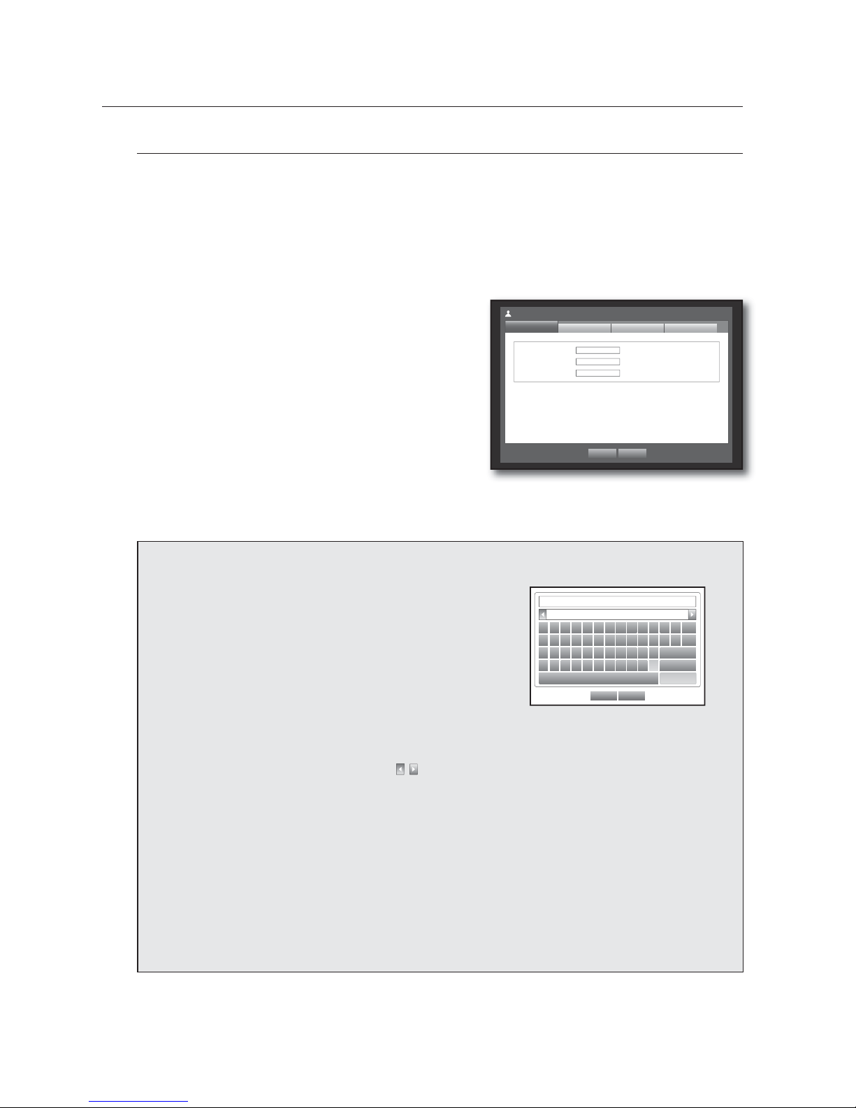
Setting the Administrator
You can set and change Administrator’s ID and password.
The administrator can use and set all menu items and functions.
Using the mouse may help make setup easier.
Use the up/down buttons () in <System> window to
move to <Permission Management>, and press
[ENTER] button.
Select <Admin>.
A dialog for Admin ID and Password input appears.
Use direction buttons (
◄ ►
) to move to a desired
item, and set the ID and password.
By default, initial ID and password are set to “admin”, and
“4321”.
When the administrator setup is done, press <OK>.
Using Virtual Keyboard
{
For alphanumeric inputs, the virtual keyboard window
appears.
|
Use direction buttons (
◄ ►
) to move to a desired
character, and press the [ENTER] button.
}
In the upper text input box of the virtual keyboard, there
displays a list of candidate words containing the selected
character.
~
Select a word from the list, or use the keyboard to enter the
whole word.
OK Cancel
`1234567890-=
o
qwe r t y u i o p [ ] \
Del
asdf gh j k l ; ‘
Caps Lock
zxcvbnm, . /
Shift
Space Ctrl
If there are many of candidate words, use < , > buttons to move between them forward and backward.
You can use mouse wheel and jog shuttle button too.
Select <OK>.
Entered word is applied.
For upper case letters, use <Caps Lock> button.
For special characters, use <Shift> button.
Using the virtual keyboard is the same to a normal keyboard use in your region.
You can enter only lower-case alphabets and numeric values for the user ID.
For the password, use alphabets and special characters excluding < \> and <“>.
You can use number buttons on the remote control or front panel.
3.
4.
5.
M
6.
x
ID admin
x
Password
********
x
&RQ¿UP3:
********
Permission Management
Admin
Group
OK Cancel
User Setup
Page 37
English _37
USING THE DVR
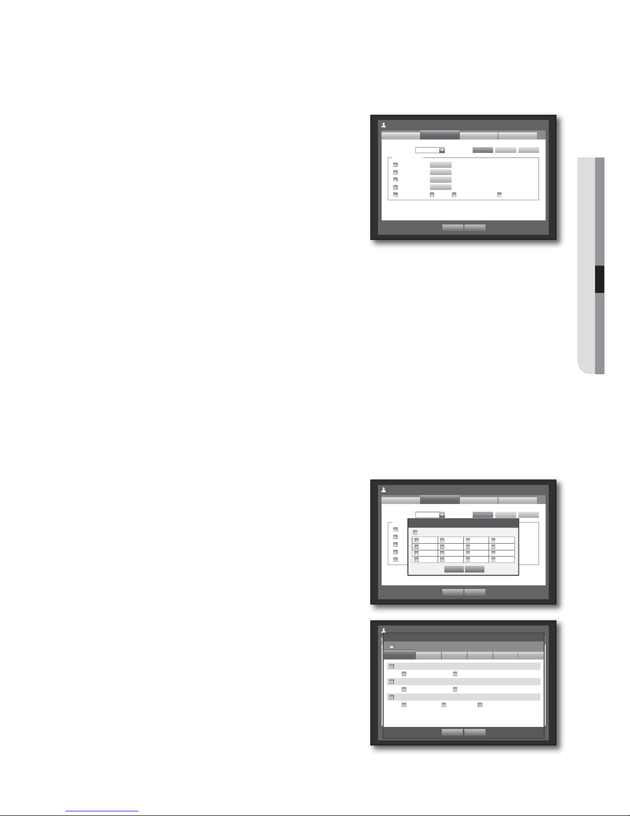
Setting the Group
You can create user groups and setup permissions for those user groups.
You can register a user for each group in <User>.
Using the mouse may help make setup easier.
Use the up/down buttons () in <System> window to
move to <Permission Management>, and press
[ENTER] button.
Select <Group>.
A window for <Add>, <Delete>, <Rename>, and
<Group Authority> setup appears.
Use direction buttons (
◄ ►
) to move to a desired
item, and set the value.
Add, Delete, Rename : You can add, delete, rename a
group or modify the permissions given to the group.
The virtual keyboard appears when <Add> or <Rename> was selected.
You can add up to 10 groups.
- Add : When you first run the DVR with the admin account, only the admin account exists. Add has already
been deactivated. Select to display the virtual keyboard. Enter a group name. You can add up to 10
groups.
- Delete : Deletes a user group that is already registered. Selecting Delete will delete all user accounts
belonging to that group.
- Rename : Renames a group that is already registered. Select <Rename> to display the virtual keyboard.
For entering a group name, refer to “Using Virtual Keyboard”. (Page 36)
Group Authority : Sets permissions to access menu items of each group.
Users of a group can access checked functions.
When the group setup is done, press <OK>.
To set the group authority
You can set the permissions of the group users to access the menu according to the channel.
Select a menu to which the group permission is assigned.
The menu where the group permission is assigned will be
displayed in the Live menu when a group user logs in.
Live View : You can set the permission to access the Live
screen according to the channel.
Search : You can set the permission to access the Search
menu according to the channel.
Backup : You can set the permission to access the Backup
menu according to the channel.
Menu : You can set menus accessible with a specific
permission.
Group users can access the permitted menus only.
Select a menu to display the Menu Permission screen.
Record Lock, PTZ, Remote Alarm Out, Shutdown : Select
an item so that the item will be added to the permissions.
Select <OK>.
Select and assign a group user so that the user can
access the specified menu.
3.
4.
5.
•
•
6.
1.
•
•
•
•
•
2.
Permission Management
Group
Admin
OK Cancel
User
Add Delete Rename
x
Group
Group Authority
Live View
Search
Backup
Menu
Record Lock PTZ Remote Alarm Out Shutdown
Setup
Setup
Setup
Setup
Setup
Permission Management
Group
Admin
OK Cancel
User
Add Delete Rename
x
Group ABC
Group Authority
Live View
Search
Backup
Menu
Record Lock PTZ Remote Alarm Out
Shutdown
Setup
Setup
Setup
Setup
Setup
Channel Setup
OK Cancel
123 4
567 8
9101112
13 14 15 16
All
Permission Management
Group
Admin
OK Cancel
User
Add Delete Rename
x
Group ABC
Group Authority
Live View
Search
Backup
Menu
Record Lock PTZ Remote Alarm Out
Shutdown
Setup
Setup
Setup
Setup
Setup
Menu Permission
OK Cancel
Date/Time/Language
Date/Time/Language Holiday
System Management
System Information Settings
Log Information
System Log Event Log Backup Log
All
System
Device Record Event Backup Network
Page 38
38_ using the DVR
VTJOHUIF%73
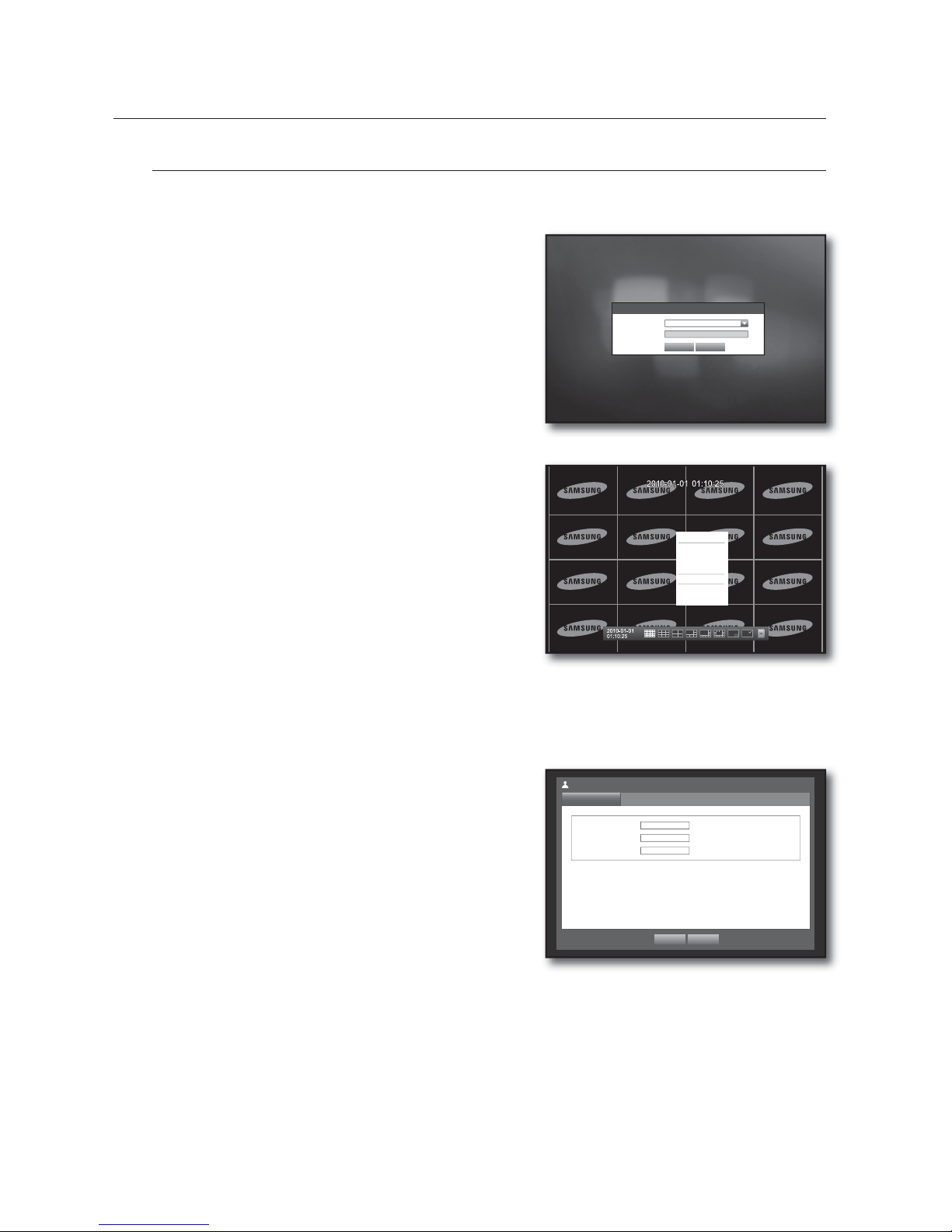
To restrict the user permissions
If the admin restricts all permissions of an added group, the users belonging to that group can access only
the default minimum menus and can change the user’s own password only.
Start the DVR.
If all permissions are restricted, only the Login dialog should
appear.
Log in with a registered user ID.
Right-click any area on the screen.
If all permissions are restricted, only the accessible context
menus should appear.
To change the user password
If you log in with a user account that is restricted to access the menu, you can change your own password
only.
Log in with your account.
Select <User Menu>.
The Permission Management setup screen appears.
Select <Permission Management>.
The Password setup dialog appears.
Enter a new password.
Select <OK>.
You change to the password will be applied.
1.
2.
3.
1.
2.
3.
4.
5.
x
ID
abc
x
Password
********
x
&RQ¿UP3:
********
Permission Management
User
OK Cancel
Scene Mode
f
Audio Off
Freeze
Stop Alarm
User Menu
Hide Launcher
Logout
Login
x
ID abc
x
Password
OK Cancel
Page 39

English _39
USING THE DVR
Setting the User
Users can be added only if a group was created in <Group> menu.
Using the mouse may help make setup easier.
Use the up/down buttons () in <System> window to
move to <Permission Management>, and press
[ENTER] button.
Select <User>.
A window for Add User appears.
Use direction buttons (
◄ ►
) to select <Add> from the
window.
A window for “Add User” appears.
You can configure the Network Viewer settings including
name, ID, viewer, Select Group and password.
Result of the user setup appears in the <User> window.
To change the user property, use “Edit User”.
The “Edit User” window appears when you select a
desired item to be changed in the <User> window.
Viewer : If you select <Use>, you will be given access to the
Web Viewer and Network Viewer.
Refer to “Connecting Web Viewer”. (Page 74)
For more information about use of Network Viewer, refer to the
Network Viewer's user guide. (Page 5)
When the user setup is done, press <OK>.
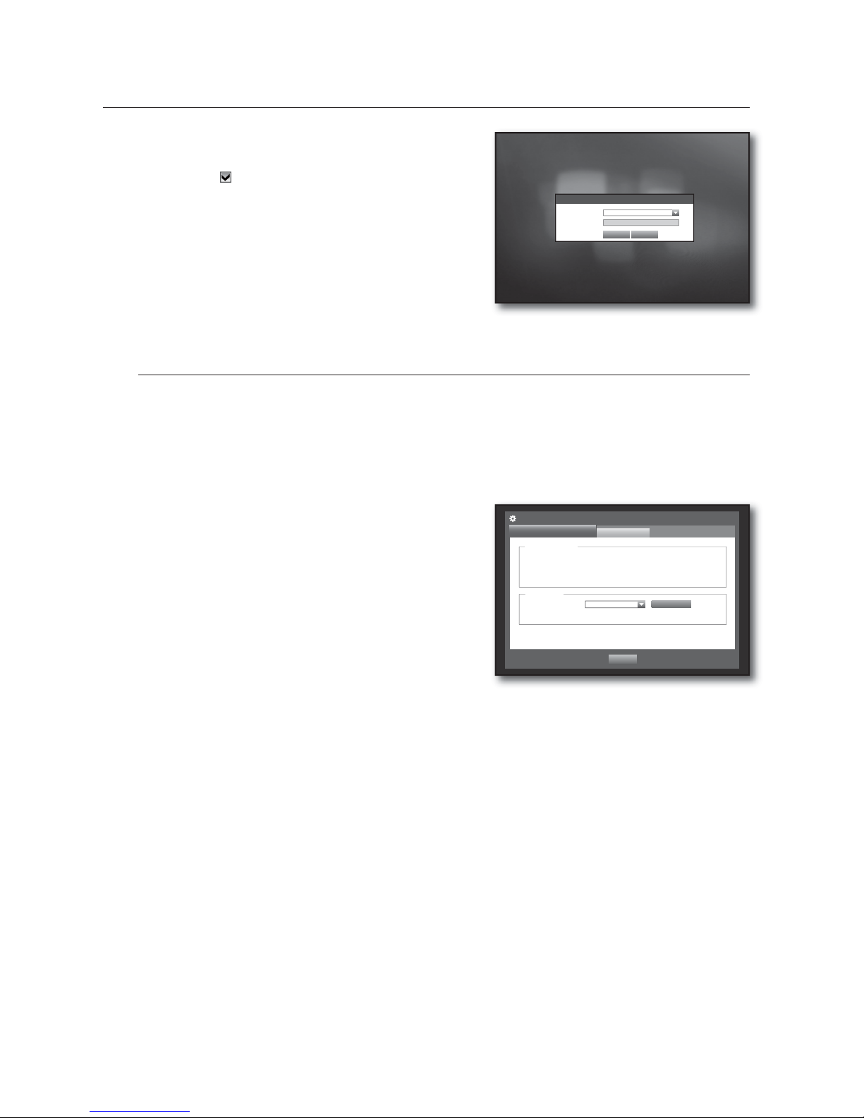
Setting Permissions
You can set restricted access for all general users.
Items with restrictions will require logging in for use.
Using the mouse may help make setup easier.
Use the up/down buttons () in <System> window to
move to <Permission Management>, and press
[ENTER] button.
Select <Setup>.
The Restricted Access, Restriction on Network Access,
Auto Log out, Manual Input of ID setup screen appear.
Use direction buttons (
◄ ►
) to move to a desired
item, and set the value.
Restricted Access : All menu items allowed for a user can
be set with restricted access.
- Checked (
) : Restricted
- Not checked ( ) : Accessible
If it is not checked ( ) in <Restricted Access>, any user can access the item no matter what the <Group Authority>
setting.
If it is checked (
) in <Restricted Access>, a user can access the item only if the user has permission in <Group
Authority> setting.
Restriction on Network Access : Restricts remote access from a <Restricted Access> network.
- All Network : Restricts all access instances via Network Viewer and Web Viewer.
- Web Viewer : Restricts access via the Web Viewer.
Auto Log out : A user will be automatically logged out if there is no operation on DVR for over set period of
time.
3.
4.
5.
•
6.
3.
4.
5.
•
•
•
Group Name ID Viewer Delete
Permission Management
User
Admin
OK Cancel
Setup
Add
Group
x
Group All Group
Previous/Next Page
Group Name ID Viewer Delete
Permission Management
User
Admin
OK Cancel
Setup
Add
Group
x
Group All Group
Previous/Next Page
Add User
OK Cancel
x
Name Kim
x
ID ksh
x
Viewer Not Used
x
Select Group ABC
x
Password
********
x
&RQ¿UP
********
Permission Management
Setup
Admin
OK Cancel
Group
Restricted Access
Live View Backup Record Lock Search
PTZ Remote Alarm Out Shutdown All
x
Auto Log out 3 min
x
Manual Input of ID ON
User
Restriction on Network Access
All Network Web Viewer
Page 40
40_ using the DVR
VTJOHUIF%73
Manual Input of ID : Prompts you to enter the user ID
manually for the login process.
- Checked (
) : Encloses the registered user IDs with the
[½] symbols.
Use the virtual keyboard to enter the user ID.
When the permission setup is done, press <OK>.
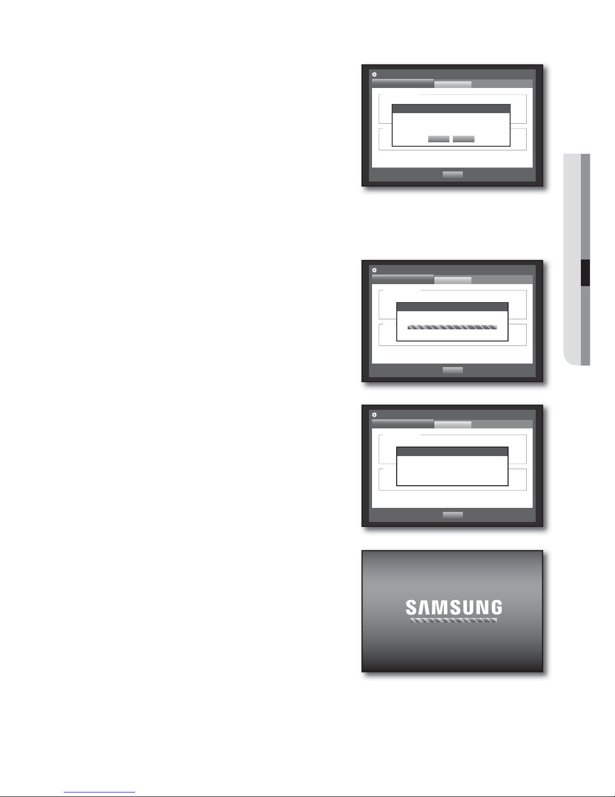
System Management
You can check the system version, update to a newer version, as well as data backup and initialization.
Checking the System Information
You can check the current system version, broadcasting system, MAC address. You can update the system.
Using the mouse may help make setup easier.
Use the up/down buttons () in <System> window to
move to <System Management>, and press [ENTER]
button.
Check the Version, Broadcast Format, and MAC Address.
System Information : Shows the current system’s
information.
The values can not be changed by a user.
S/W Upgrade : Updates the DVR’s software up to date.
•
6.
3.
4.
•
•
x
Software Version V1.00h_100315180929
x
Broadcast Format
NTSC
x
MAC Address 00:00:F0:54:FF:FF
System Management
System Information
Settings
Previous
System Information
Upgrade
x
Device USB2FlashStorage
x
Version V1.00h_100315180929
S/W Upgrade
Login
x
ID
*****
x
Password
OK Cancel
Page 41
English _41
USING THE DVR
Updating the Software
Connect a device storing the software to be updated.
(It may take about 10 seconds to recognize the device.)
Upgradeable devices include USB memory, CD/DVD and
network device.
To update the network, the current DVR should have been
connected to the network.
Upgrade via the proxy server may not be enabled due to the
restricted access.
Select <System Management> from <System> window.
Select <System Information>.
When the recognized device appears, select <Upgrade>.
The <Upgrade> button will be activated only if the current <Software Version> of the <System Information> is
same to or older than that of <S/W Upgrade>.
Press <OK> in the “System Upgrade” window.
While updating, it shows the progress.
Updating progresses with 3 steps as shown in the figure.
When the updating is done, it automatically restarts.
Do not turn the power off until it finishes restarting.
If “Upgrade Failed” appears, retry from the step 4.
When you experience continued failure, consult the service
center for assistance.
•
1.
2.
3.
4.
5.
•
6.
M
x
Software Version V1.00h_100315180929
x
Broadcast Format
NTSC
x
MAC Address 00:00:F0:54:FF:FF
System Management
System Information
Settings
Previous
System Information
Upgrade
x
Device USB2FlashStorage
x
Version V1.08_090731170402
S/W Upgrade
System Upgrade
OK Cancel
Current Version V1.00h_100315180929
New Version V1.00h_100320180929
Do you want to upgrade?
x
Software Version V1.00h_100315180929
x
Broadcast Format
NTSC
x
MAC Address 00:00:F0:54:FF:FF
System Management
System Information
Settings
Previous
System Information
Upgrade
x
Device USB2FlashStorage
x
Version V1.08_090731170402
S/W Upgrade
S/W Upgrade
Software upgrading...
x
Software Version V1.00h_100315180929
x
Broadcast Format
NTSC
x
MAC Address 00:00:F0:54:FF:FF
System Management
System Information
Settings
Previous
System Information
Upgrade
x
Device USB2FlashStorage
x
Version V1.08_090731170402
S/W Upgrade
S/W Upgrade
Software upgrading...
S/W Upgrade
Software upgrading...
Do not turn off during the upgrade.
Page 42
42_ using the DVR
VTJOHUIF%73
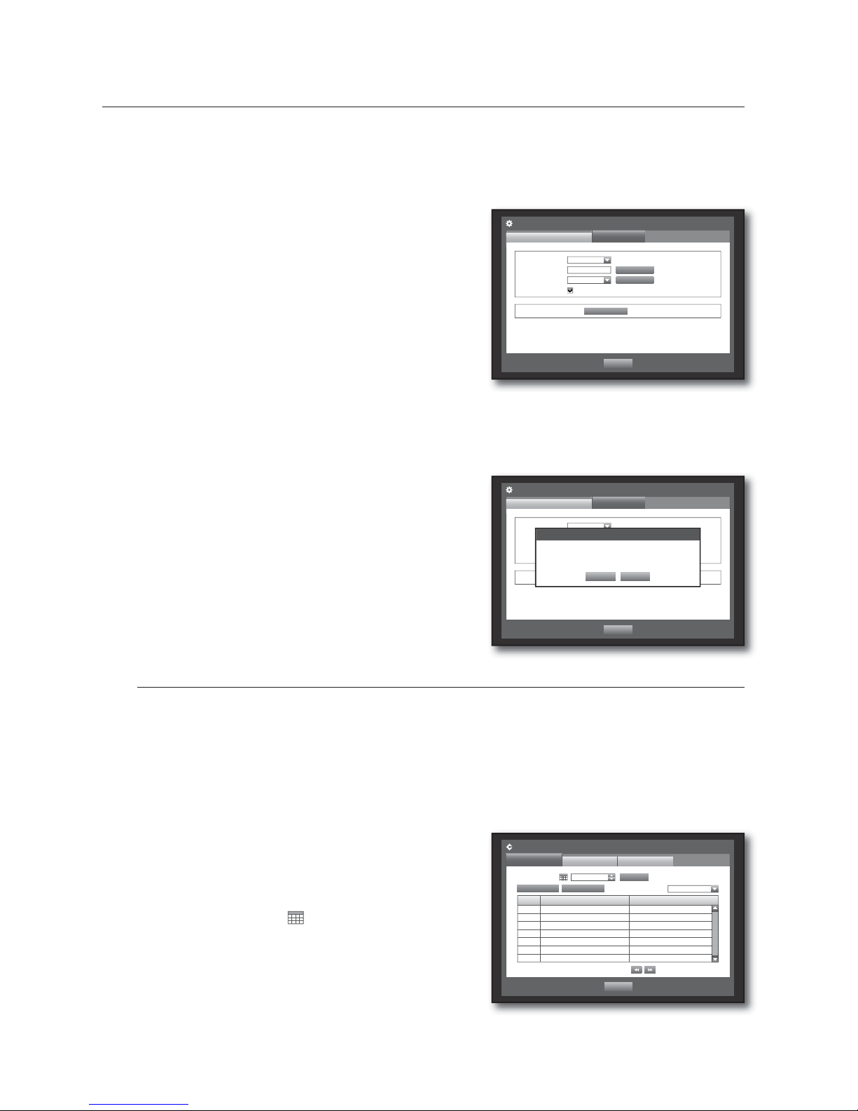
Settings
You can copy and import the DVR settings by using a storage media.
Using the mouse may help make setup easier.
Use the up/down buttons () in <System> window to
move to <System Management>, and press [ENTER]
button.
Select <Settings>.
A window of storage device and load factory default
appears.
Use direction buttons (
◄ ►
) to move to a desired
item, and export or import settings data to a storage
device.
Storage Device : Shows the connected storage device.
Export : Exports DVR settings to the connected storage device.
Import : Imports DVR settings from the storage device and applies to the DVR.
If <Include Network Settings> is checked, the network settings will be imported too.
Load Factory Default : If <Default> is selected, a
confirmation dialog for “Load Factory Default” prompts.
Press <OK> to initialize the system to the factory default.
To move to the previous menu, press <Previous>.
Log Information
You can browse logs on the system and events.
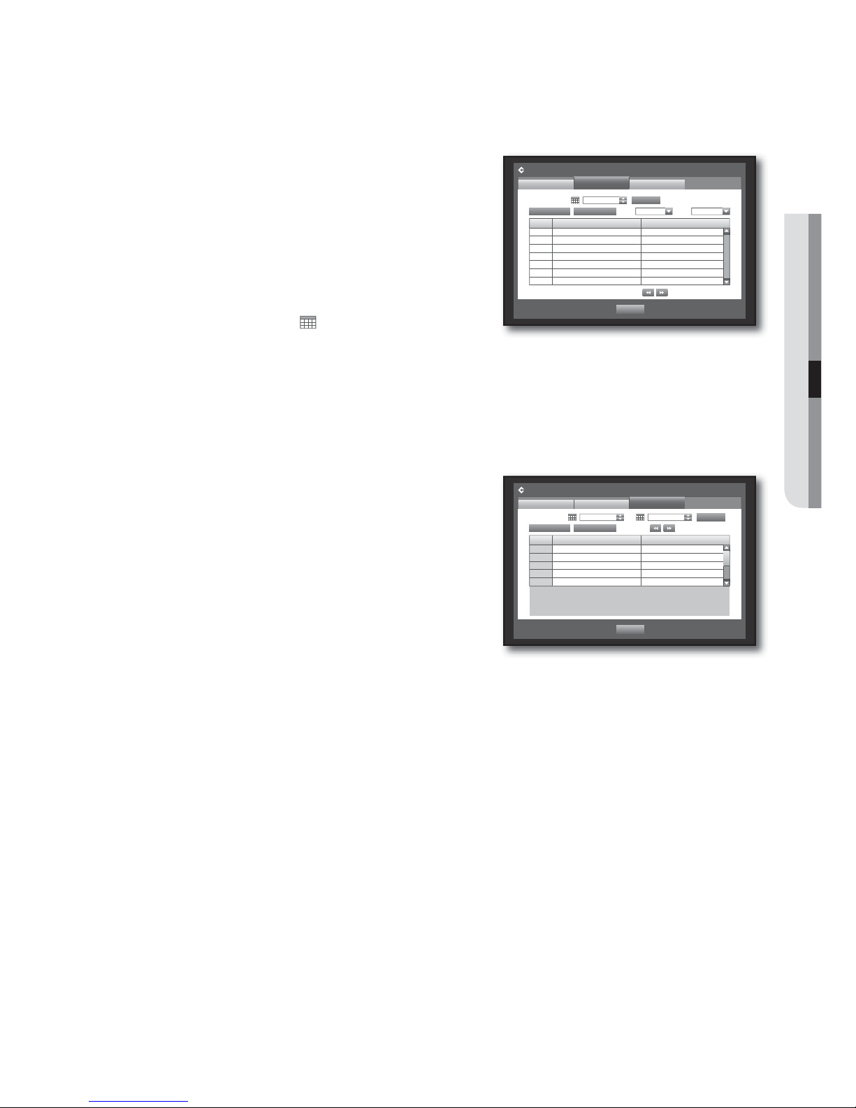
System Log
System Log shows log and timestamp on every system start up, system shutdown, and changes on system
settings.
Using the mouse may help make setup easier.
Use the up/down buttons () in <System> window to
move to <Log Information>, and press [ENTER] button.
Select <System Log>.
Refer to “Using the Calendar”. (Page 35)
Click on the calendar < > to display the calendar window.
Type : When there are too many logs, you can display logs of
the desired format by selecting the type.
Use direction buttons (
◄ ►
) to move to a desired item,
and press <Search>.
3.
4.
5.
•
•
•
•
6.
3.
4.
•
5.
x
Storage Device 1932 MB (Remained Capacity)
x
DVR
p
USB 38010100
x
USBpDVR
Include Network Settings
Settings
System Information
Previous
x
Load Factory Default
Default
Export
Import
System Management
Load Factory Default
OK Cancel
Sure to Default Setting?
x
Storage Device 1932 MB (Remained Capacity)
x
DVR
p
USB 38010100
x
USBpDVR
Include Network Settings
Settings
System Information
Previous
x
Load Factory Default
Default
Export
Import
System Management
No. Log List Date/Time
Log Information
System Log
Event Log
First Page
Search Day 2010-01-01
Previous
Previous/Next Page
Type View all
Search
Last Page
Backup Log
Page 43
English _43
USING THE DVR
Event Log
Event log shows recorded events on alarms, motion detections and video loss.
It also shows the log and its timestamp.
Using the mouse may help make setup easier.
Use the up/down buttons () in <System> window to
move to <Log Information>, and press [ENTER] button.
Select <Event Log>.
Use direction buttons (
◄ ►
) to move to the desired
item.
Set Search Day, Channel and Type and the press
<Search>.
Refer to “Using the Calendar”. (Page 35)
Click on the calendar < > to display the calendar window.
Backup Log
You can find out who backed up and the details (backup time, channel, device to use, file format, etc.).
Using the mouse may help make setup easier.
In the <System> window, press the up/down () button
to move to <Log Information> and press the [ENTER]
button.
Select <Backup Log>.
Use the four direction buttons (
◄ ►
) to move to a
desired item.
Specify a search term and select <Search> in the right
corner.
Backup details for the search term will be listed.
3.
4.
5.
6.
3.
4.
5.
6.
No. Log List Date/Time
7 Motion Detection [CH 7] 2010-01-01 00:02:18
6 Motion Detection [CH 6] 2010-01-01 00:02:18
5 Motion Detection [CH 5] 2010-01-01 00:02:18
4 Motion Detection [CH 4] 2010-01-01 00:02:18
3 Motion Detection [CH 3] 2010-01-01 00:02:18
2 Motion Detection [CH 2] 2010-01-01 00:02:18
1 Motion Detection [CH 1] 2010-01-01 00:02:18
Log Information
Event Log
System Log
First Page
Search Day 2010-01-01
Previous
Previous/Next Page
CH All CHs Type View all
Search
Last Page
Backup Log
No. User Date/Time
Log Information
Backup Log
System Log
First Page
Search Day 2010-01-01 ~ 2010-01-02
Previous
Previous/Next Page
Search
Last Page
Event Log
Page 44

44_ using the DVR
VTJOHUIF%73
SETTING THE DEVICE
You can setup Camera, Storage Device, Remote Device, POS Device and Monitor.
Camera
Setting the Camera
You can set Video, Audio, Channel Name and Dwell Time of a Camera.
Using the mouse may help make setup easier.
Press the [MENU] button on the remote control or front
panel.
Use the left/right button (
◄ ►
) to select <Device>.
Device setting menu is selected.
Use the up/down buttons (
) to move to <Camera>,
and press [ENTER] button.
Select <Camera>.
You will see a window where you can configure the
camera settings including Video, Audio, Channel Name,
Dwell Time and Progressive.
Use direction buttons (
◄ ►
) to move to a desired
item, and set the value.
Video
-<ON/OFF
> : You can turn ON/OFF the selected
channel’s camera.
-<Covert1> : Shows information other than the video of the selected channel.
For privacy protection, it does not display the video while the recording continues.
-<Covert2> : Shows nothing but an empty screen while the recording continues.
No signal will be output from channels that are set to <Covert1> or <Covert2> for the video.
However, audio recording will be performed for a channel whose audio is set to <ON> even if no audio signal is
output from the Live screen.
Audio
- If set to <ON>, you can turn the audio of the channel ON/OFF on the Live screen.
- If set to <OFF>, the channel’s audio is off on the Live screen and not recorded.
Audio output is available for only 1 channel.
SRD-830DC/1610DC/1630DC supports 1~4 channels of sound inputs.
1.
2.
3.
4.
5.
•
M
•
M
Device
Logout
Exit
Camera
Storage Device
Remote Device
POS Device
Monitor
CH Video
b
Audio bCH Name SEQ-Dwell Time
b
Progressive
b
1ON
b
OFFbCAM 01 5 sec
b
OFF
b
2ON
b
OFFbCAM 02 5 sec
b
OFF
b
3ON
b
OFFbCAM 03 5 sec
b
OFF
b
4ON
b
OFFbCAM 04 5 sec
b
OFF
b
5ON
b
OFFbCAM 05 5 sec
b
OFF
b
6ON
b
OFFbCAM 06 5 sec
b
OFF
b
7ON
b
OFFbCAM 07 5 sec
b
OFF
b
8ON
b
OFFbCAM 08 5 sec
b
OFF
b
Camera
Camera
PTZ
Previous/Next Page
Screen Setup
OK Cancel
Page 45
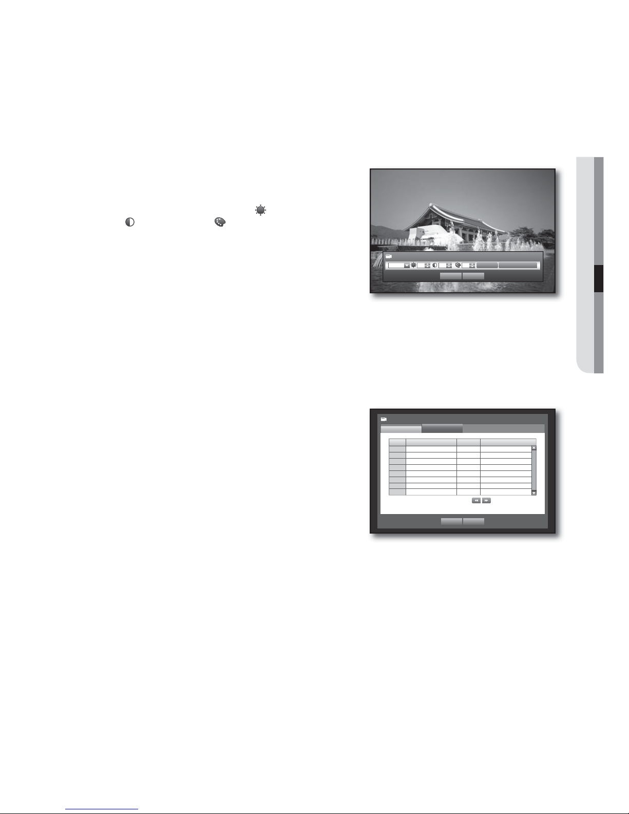
English _45
USING THE DVR
CH Name : Up to 15 characters including blanks are allowed.
Refer to “Using Virtual Keyboard”. (Page 36)
SEQ-Dwell Time : You can set the dwell time between channels for the Live screen and Spot Out.
If set to <OFF>, the channel is not listed in the Auto Sequence mode.
Progressive : You can set the progressive camera to ON/OFF.
If you set it to <ON> for the progressive camera, screen flickering will be reduced.
Screen Setup : The video appeared on the screen may vary
depending on the channel’s camera, configure the DVR
display to your preferences.
Select a channel and adjust the
<
(Brightness)>,
<
(Contrast)>, and <(Color)> of the selected channel.
Press the <Init> to initialize settings back to the default 50.
When the camera setup is done, press <OK>.
Setting the PTZ
If you want to enable the PTZ functions of a camera from the DVR, you should match the Port, ID and
protocol between each applicable camera and DVR.
For other settings, refer to the “Remote Devices” settings. (Page 48)
Using the mouse may help make setup easier.
Use the up/down buttons () in <Device> window to
move to <Camera>, and press [ENTER] button.
Select <PTZ>.
A window of PTZ settings appears.
Use direction buttons (
◄ ►
) to move to a desired
item, and select it.
Port : Select a port control method for the camera that is
connected to a channel.
You have two choices : <RS-485> and <Coaxial>.
ID : Set the ID of the connected camera of each channel.
You can easily setup by using the numeric buttons on the remote control or front panel.
Protocol : Set the protocol of the connected camera of each channel.
You can check the camera’s ID and protocol if you turn the camera off and on after connecting it to the DVR.
(Page 67)
For the <Coaxial> type, CCVC and PELCO-C protocols are supported.
When the PTZ setup is done, press <OK>.
•
•
•
J
•
•
6.
3.
4.
5.
•
•
•
M
6.
Screen Setup
Init Apply to All CH
CH1 50 50 50
OK Cancel
CH Port
b
ID Protocol
1 RS-485 0
>
SAMSUNG-E
b
2 RS-485 1
>
SAMSUNG-E
b
3 RS-485 2
>
SAMSUNG-E
b
4 RS-485 3
>
SAMSUNG-E
b
5 RS-485 4
>
SAMSUNG-E
b
6 RS-485 5
>
SAMSUNG-E
b
7 RS-485 6
>
SAMSUNG-E
b
8 RS-485 7
>
SAMSUNG-E
b
Camera
PTZ
Camera
Previous/Next Page
OK Cancel
Page 46
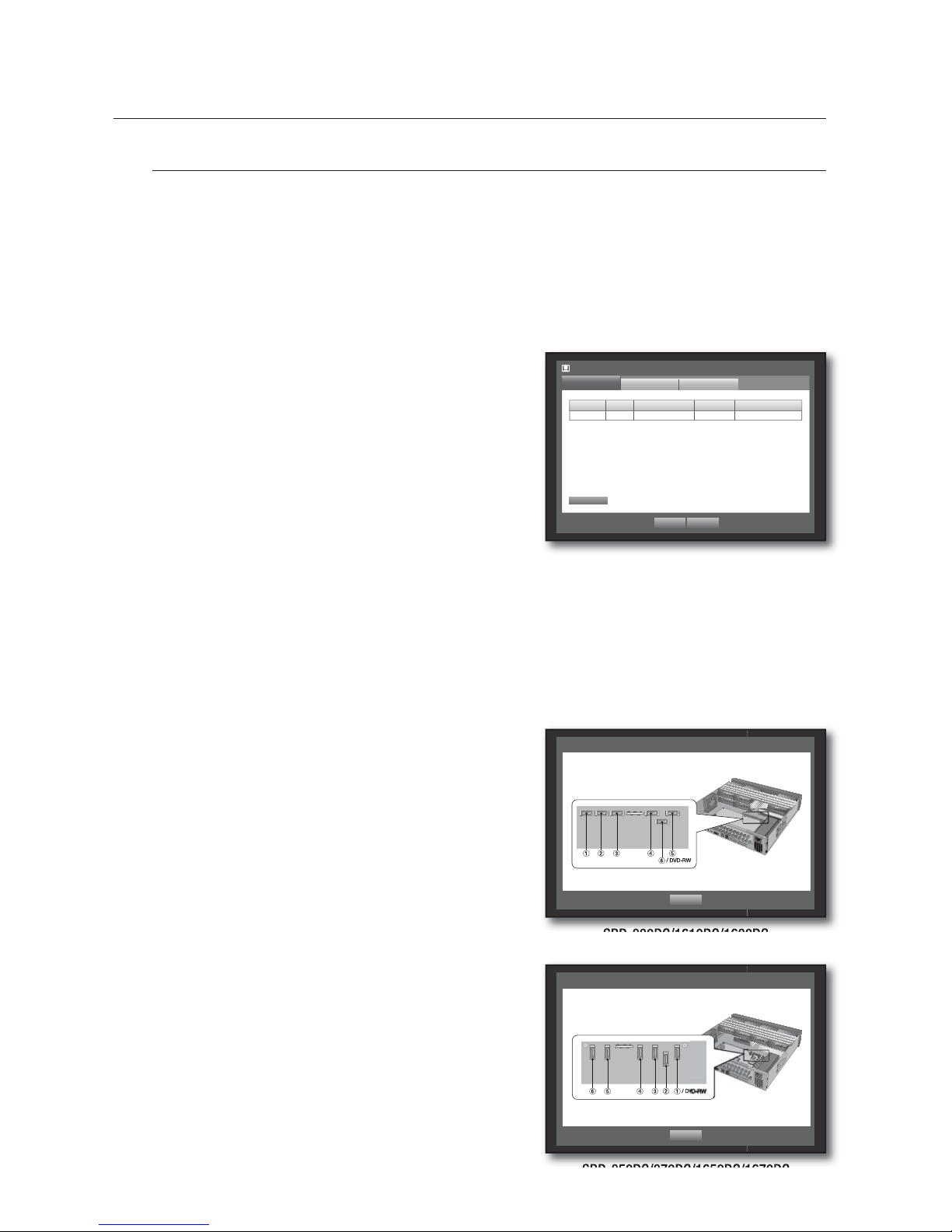
46_ using the DVR
VTJOHUIF%73
Storage Device
You can check information on storage devices.
Confirming Devices
You can check storage devices and their free space, usage as well as status.
Devices available are HDD, and USB devices (Memory, HDD, CD/DVD).
Refer to “Product Specifications > Backup”. (Page 98)
Using the mouse may help make setup easier.
Use the up/down buttons () in <Device> window to
move to <Storage Device>, and press [ENTER] button.
Select <Device>.
No. : Shows the assigned number of the internal HDD.
To see the detailed positioning of the HDD according to the
number, refer to <HDD Map>.
Used/Total : Shows the used/total capacity of the storage
device.
Usage : Sets the storage device’s usage.
- USB memory is used only for backups.
External USB HDD, SATA HDD are used for extension and backup.
SRD-830DC/1610DC/1630DC does not support a port for SATA connection.
Status/Management : Shows the current status of the HDD, as in Normal/Check/Replace.
- Normal : Available to use
- Check : Available to use but recommended to replace
- Replace : Requires immediate replacement.
HDD Map : Shows the internal HDD’s locations according to
assigned numbers.
Refer to this for servicing or additional HDD installation.
To move to the previous menu, press <OK>.
3.
4.
•
•
•
•
•
5.
Storage Device
Device
Format
OK Cancel
HDD Alarm
HDD Map
Device No. Used/Total Usage Status/Management
HDD 1 12.28G/499.37G Internal Normal
<SRD-830DC/1610DC/1630DC>
HDD Map
OK
<SRD-850DC/870DC/1650DC/1670DC>
HDD Map
OK
Page 47
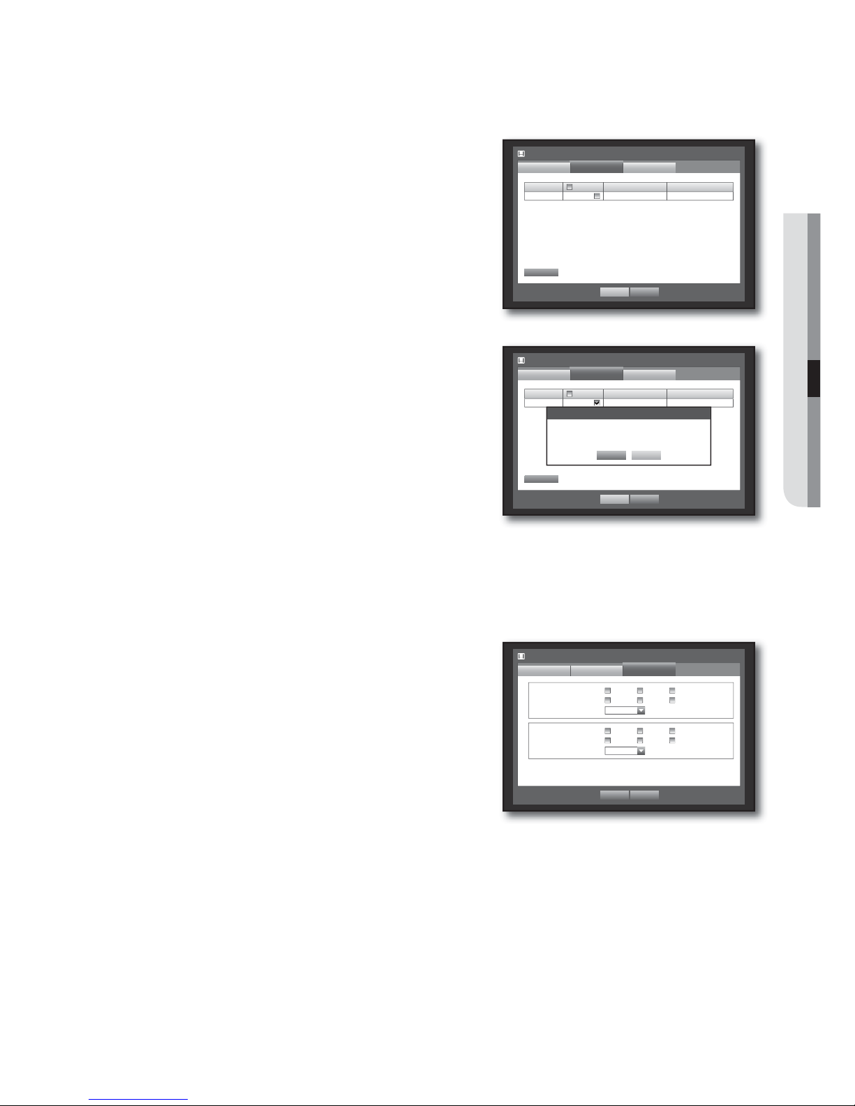
English _47
USING THE DVR
Formatting
You can format a storage device.
Using the mouse may help make setup easier.
Use the up/down buttons () in <Device> window to
move to <Storage Device>, and press [ENTER] button.
Select <Format>.
A window for selection of device for formatting appears.
Use direction buttons (
◄ ►
) to select a device to be
formatted.
Select <Format> on the bottom of the screen.
Press <OK> on the “Manage” confirmation window will
start formatting the selected device.
When the formatting is done, press <OK>.
HDD Alarm
You can set alarm settings for HDD defects such as Check Alarm Output Port, Replace Alarm Output Port,
and its duration.
Using the mouse may help make setup easier.
Use the up/down buttons () in <Device> window to
move to <Storage Device>, and press [ENTER] button.
Select <HDD Alarm>.
A window for setting HDD check and replace output ports
and their durations appears.
Use direction buttons (
◄ ►
) to move to the desired
item.
Alarm
- Alarm signal will output through the alarm out port on the
rear side when selected <1>, <2>, <3>, and <4>.
- If <BEEP> was selected, a beep will sound.
- If <All> was selected, both beep sound and alarm signal through rear side ports will output.
Check Alarm Output Port : If HDD generates check alarm, the alarm signal will output to the specified alarm
output port.
Replace Alarm Output Port : If HDD generates replace alarm, the alarm signal will output to the specified
alarm output port.
3.
4.
5.
6.
7.
3.
4.
5.
•
•
•
Storage Device
Device
OK Cancel
HDD Alarm
Format
Device Select Used/Total Usage
HDD 1 12.28G/499.37G Internal
Format
Storage Device
Format
OK Cancel
Device
HDD Alarm
x
Check Alarm Output Port
x
Duration OFF
123
4 BEEP All
x
Replace Alarm Output Port
x
Duration OFF
123
4 BEEP All
Storage Device
Device
OK Cancel
HDD Alarm
Format
Device Select Used/Total Usage
HDD 1 12.28G/499.37G Internal
Format
Manage
Formatting deletes all recordings.
Proceed formatting?
OK Cancel
Page 48
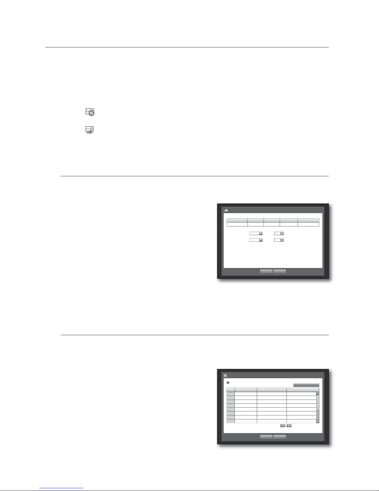
48_ using the DVR
VTJOHUIF%73
Duration : Sets the alarm duration for the alarm signal and beep sound.
- Check Alarm, Replace Alarm signals will output through the selected alarm out ports (1, 2, 3, and 4).
- If <BEEP
> was selected, a beep will sound.
- If <All> was selected, both beep sound and alarm signal through rear side ports will output.
<Check> status means that the HDD is operating but it has problems that require technical examination.
(
) appears on the Live screen.
<Replace> status means that the HDD has defect and requires immediate replacement.
(
) appears on the Live screen.
When the HDD Alarm setup is done, press <OK>.
Remote Devices
You can set the RS-485 communication for use of PTZ Camera and system keyboard with the DVR.
Using the mouse may help make setup easier.
Use the up/down buttons () in <Device> window to
move to <Remote Device>, and press [ENTER] button.
Use direction buttons (
◄ ►
) to move to the desired
item, and press [ENTER] button.
Set the values of each communication setup of the remote
device.
Baudrate : Baud rate settings of the DVR, PTZ camera and
system keyboard should be matched for proper operations.
Make sure to match IDs of the DVR, System Keyboard
and Remote Control, and press <OK>.
For changing the remote control’s ID, refer to “Changing the Remote Control ID”. (Page 13)
POS Devices
You can set properties of POS devices connected to the DVR.
A POS device connection requires channel, preset, and Port/Ethernet settings.
Using the mouse may help make setup easier.
Use the up/down buttons () in <Device> window to
move to <POS Device>, and press [ENTER] button.
Use direction buttons (
◄ ►
) to move to a desired
item, and set the value.
POS USE : When selected <POS USE>, DVR and POS will
be connected.
If you change settings for the device and press <OK> while
the <POS USE> is not checked, the changes for POS device
will not be saved.
•
M
6.
3.
4.
5.
•
6.
M
3.
4.
•
J
System Keyboard OFF ID 00
Remote Control ON ID 00
Baudrate Parity Data Stop Bit Transfer type
9600
b
None
b
8
b
1
b
Half Duplex
b
Remote Device
OK Cancel
POS USE
POS CH Preset
b
Port/Ethernet
1 None No preset None
2 None No preset
None
3 None No preset
None
4 None No preset
None
5 None No preset
None
6 None No preset
None
7 None No preset
None
8 None No preset
None
POS Device
OK Cancel
Previous/Next Page
POS Device Setup
Page 49
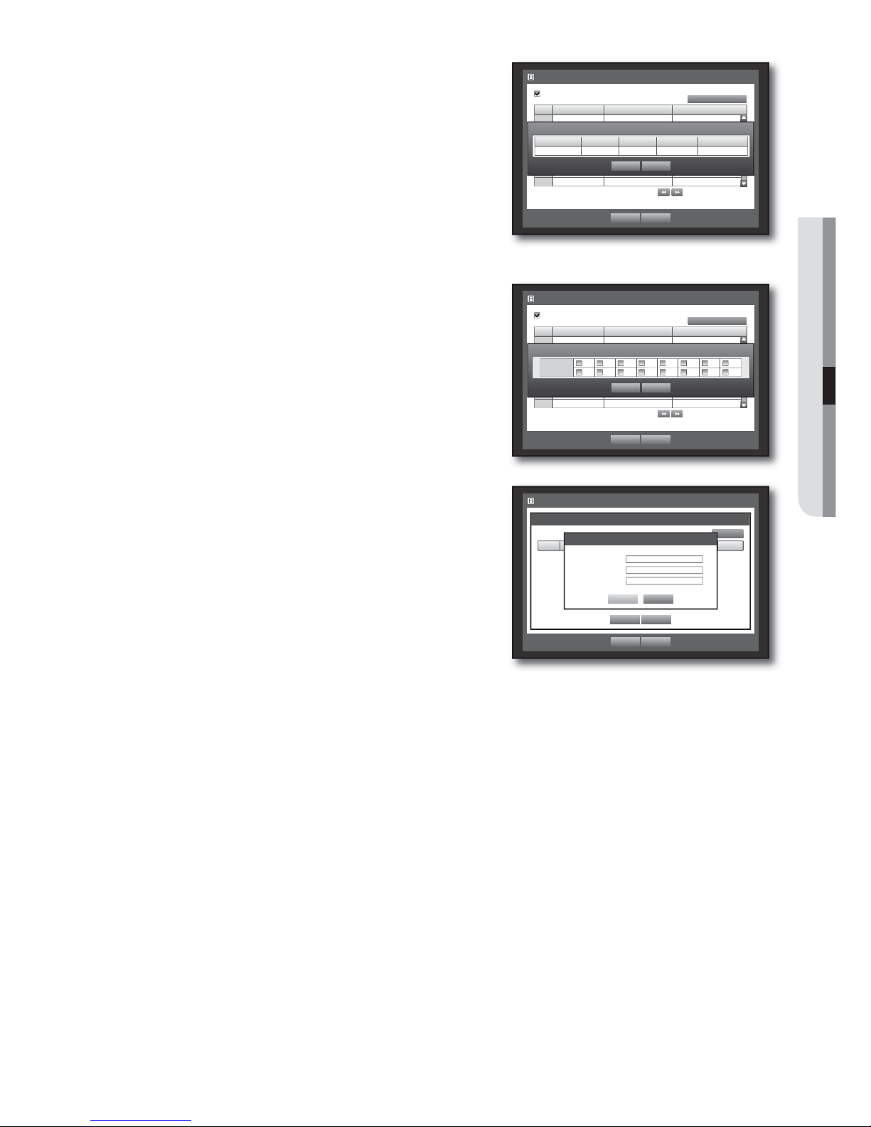
English _49
USING THE DVR
POS Device Setup : Sets the communication setups for the
POS device and DVR.
It is independent to the Remote Device setup.
CH : Select the camera to be synchronized to the POS
device.
If selected a channel input field, “Sync Channel Setup” window
appears.
One POS device can be synchronized to up to 16 cameras
(channels), however one channel cannot be synchronized to
multiple POS devices.
Channels to be synchronized to a POS device should be set to
“Event” in “Main Menu > Record > Recording Schedule”.
(Page
52)
Preset : Sets the name, start and end strings of the receipt
for the preset.
Preset name should be unique.
Use <Add> button to display “Add Preset” window, and set its
name, start string, and end string.
Port/Ethernet : Sets the port number for the DVR and POS
device connection.
COM1 : For RS-232C connections
7001~7016 : For Ethernet connections
When the POS Device setup is done, press <OK>.
•
•
•
•
5.
POS USE
POS CH Preset
b
Port/Ethernet
1 None No preset None
2 None No preset
None
3 None No preset
None
4 None No preset
None
5 None No preset
None
6 None No preset
None
7 None No preset
None
8 None No preset
None
POS Device
OK Cancel
Previous/Next Page
POS Device Setup
POS Device Setup
OK Cancel
Baudrate Parity Data Stop bit Transfer type
9600
b
None
b
8
b
1
b
Half Duplex
b
POS USE
POS CH Preset
b
Port/Ethernet
1 None No preset None
2 None No preset
None
3 None No preset
None
4 None No preset
None
5 None No preset
None
6 None No preset
None
7 None No preset
None
8 None No preset
None
POS Device
OK Cancel
Previous/Next Page
POS Device Setup
Sync Channel Setup
OK Cancel
12 34 56 78
910111213141516
CH
POS USE
POS CH Preset Port/Ethernet
1 None No preset None
2 None No preset
None
3 None No preset
None
4 None No preset
None
5 None No preset
None
6 None No preset
None
7 None No preset
None
8 None No preset
None
POS Device
OK Cancel
Previous/Next Page
POS Device Setup
Preset Setup
OK Cancel
Add
No. Name Start End Input char. Set Del
Add Preset
OK Cancel
x
Name
x
Start Keyword
x
End Keyword
Page 50
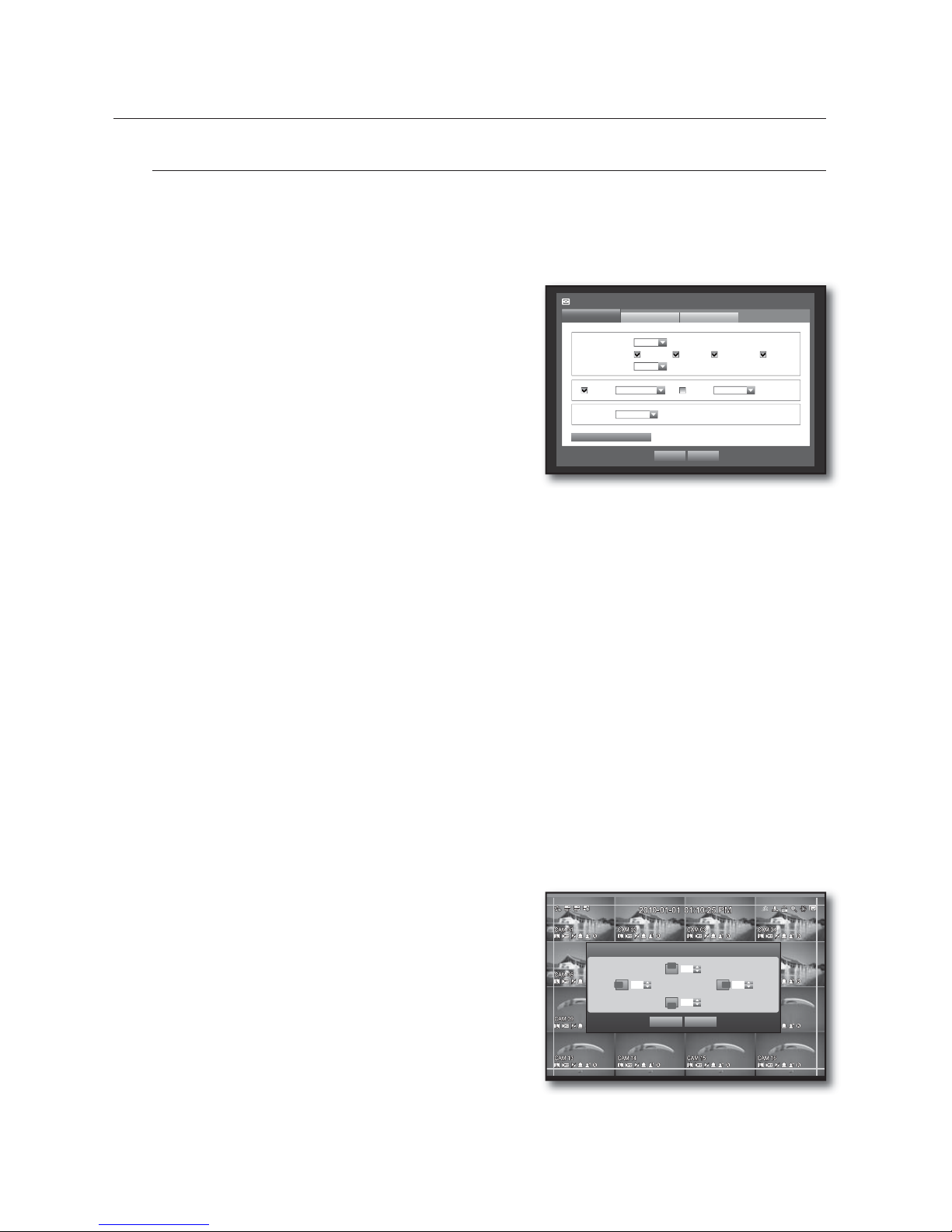
50_ using the DVR
VTJOHUIF%73
Monitor
You can configure information to be displayed and its format for Spot Out monitor.
Setting the Monitor
Using the mouse may help make setup easier.
Use the up/down buttons () in <Device> window to
move to <Monitor>, and press [ENTER] button.
Select <Monitor>.
Use direction buttons (
◄ ►
) to move to a desired
item, and set the value.
Event Display : Sets the dwell time of the event channel
display on the monitor when an event occurs.
If selected <Continuous>, it displays the channel until you
press [ALARM] button to release it.
Display : Displays only checked items on the monitor
screen.
Multi CH SEQ Time : Sets the interval between automatic display switching in 4-split and 9-split mode of
the Live screen.
VGA, HDMI : Select between <VGA> and <HDMI> for screen output.
Outputs either one of <VGA> and <HDMI>.
If the output setting of <VGA> or <HDMI> does not match to the monitor, video may not be produced.
In this case, press and hold the [MODE] and [ZOOM] buttons simultaneously for around 5 seconds to
change the video output.
SRD-830DC/1610DC/1630DC does not support the HDMI signal.
Sharpness : You can adjust the sharpness of the video output signal.
When the monitor setup is done, press <OK>.
Screen Setup
Some monitors many not display information (camera name, icon, time information, etc.) about the DVR,
depending on the condition. Then, you can change the display position of the data.
In the <Device> window, press the up/down (
) button to move to <Monitor> and press the [ENTER]
button.
Select the <Monitor> item.
Select <Display Position Setup> in the bottom.
You will move to the <Display Position Setup> window.
Use the four direction buttons or the number buttons on
the front panel or the remote control to adjust the data
position.
3.
4.
5.
•
•
•
•
•
6.
3.
4.
5.
6.
Display Position Setup
OK Cancel
30 30
30
30
Monitor
Monitor
Spot Out
x
Event Display OFF
x
Display Date Time CH Name Icon
x
Multi CH SEQ Time
5 sec
VGA 800x600 HDMI 480p
x
Sharpness
Level1 (Low)
Mode
OK Cancel
Display Position Setup
Page 51
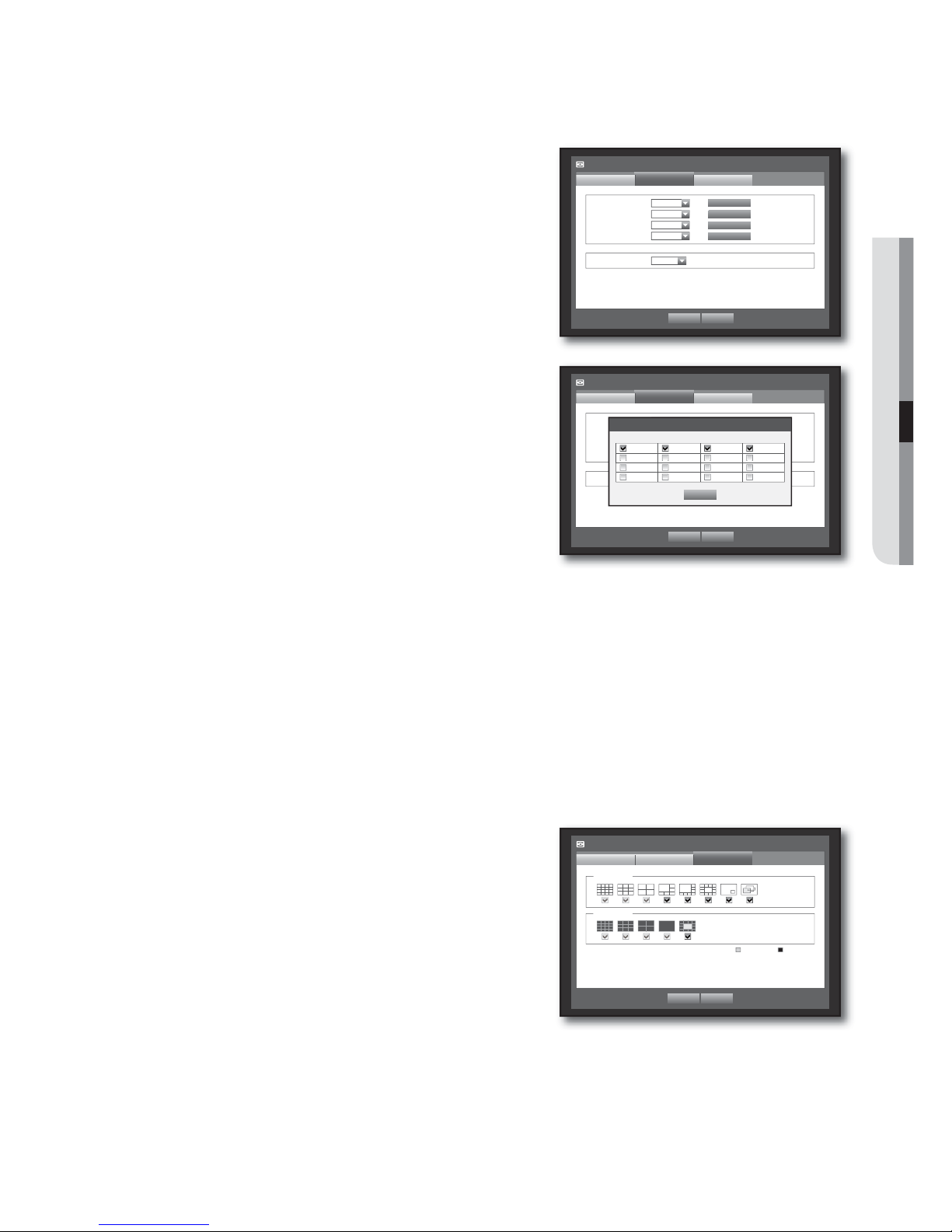
English _51
USING THE DVR
Setting the Spot Out
You can set the DVR to output information / video apart from the monitor out.
Using the mouse may help make setup easier.
Use the up/down buttons () in <Device> window to
move to <Monitor>, and press [ENTER] button.
Select <Spot Out>.
The number of Spot Out terminals differs according to the
model.
Use direction buttons (
◄ ►
) to move to a desired
item, and set the value.
Spot Out 1 : You can select between 16-, 9-, 4-split, Auto
Sequence, and Single.
Spot Out 2~4 : Only supports 4 channels, with 4-split, Auto
Sequence, and Single mode.
Set Mode : A window for “Set Spot Out” appears and you
can set the channel for it.
You can set the dwell time between the screen switching in
“Setting the Device > Camera > SEQ-Dwell Time”.
(Page
44)
Event Display : Sets the duration for the Spot Out on an
event.
If selected <OFF>, an event will not output to the Spot Out.
You can setup using the mouse right button in Live screen.
Refer to “Spot Out”. (Page 31)
When the Spot Out is done, press <OK>.
Setting the Screen Mode
You can configure the Live screen and Split Screens.
Using the mouse may help make setup easier.
Use the up/down buttons () in <Device> window to
move to <Monitor>, and press [ENTER] button.
Select <Mode>.
Use direction buttons (
◄ ►
) to move to a desired
item, and set the value.
Live Screen : Select split modes for the Live screen.
16-, 9-, and 4-split screens are included by default.
Play Screen : Select split modes for the playback screen.
Only the 13-split screen is optional.
Black shows the playback while white shows the Live
screen.
When the screen mode setup is done, press <OK>.
3.
4.
5.
•
•
•
•
M
6.
3.
4.
5.
•
•
6.
Monitor
Spot Out
Monitor
x
Spot Out 1 4-split
x
Spot Out 2 4-split
x
Spot Out 3 4-split
x
Spot Out 4 4-split
x
Event Display OFF
Mode
OK Cancel
Set Mode
Set Mode
Set Mode
Set Mode
CH 1,2,3,4
CH 5,6,7,8
CH 9,10,11,12
CH 13,14,15,16
Monitor
Mode
Monitor Spot Out
OK Cancel
Live Play
Live Screen
Play Screen
Monitor
Spot Out
Monitor
x
Spot Out 1 16-split
x
Spot Out 2 4-split
x
Spot Out 3 4-split
x
Spot Out 4 4-split
x
Event Display OFF
Mode
OK Cancel
Set Mode
Set Mode
Set Mode
Set Mode
ALL CH
CH 5,6,7,8
CH 9,10,11,12
CH 13,14,15,16
Set Spot Out
OK
1234
5678
9101112
13 14 15 16
Page 52
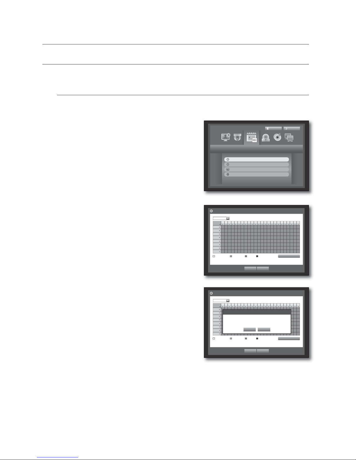
52_ using the DVR
VTJOHUIF%73
SETTING THE RECORDING
You can setup scheduled recording, event recording and other recording related settings.
Recording Schedule
Make your reservation on a date and time to schedule the recording on specified time.
Using the mouse may help make setup easier.
Press the [MENU] button on the remote control or front
panel.
Use the left/right button (
◄ ►
) to select <Record>.
Record menu is selected.
Use the up/down buttons () to move to <Recording
Schedule>, and press [ENTER] button.
Select <Recording Schedule>.
A window of scheduled recording setup appears.
Use direction buttons (
◄ ►
) to move to a desired
item, and set the value.
Apply to All CH : If selected <Apply to All CH>, “Apply to
All CH” window appears.
Press <OK> to apply the setup to all channels.
When the recording schedule setup is done, press <OK>.
Event recording and scheduled recording starts about 3
seconds prior to the event/schedule for guaranteed recording.
1.
2.
3.
4.
5.
•
6.
M
Record
Logout
Exit
Recording Schedule
Event Record Duration
REC Quality & Resolution
Record Option
All
0 1 2 3 4 5 6 7 8 9 10 11 12 13 14 15 16 17 18 19 20 21 22 23
Sun
Mon
Tue
Wed
Thu
Fri
Sat
Hol
No Recording Continuous Event Both(Cont&Evnt)
Apply to All CH
OK Cancel
Recording Schedule
CH1
All
0 1 2 3 4 5 6 7 8 9 10 11 12 13 14 15 16 17 18 19 20 21 22 23
Sun
Mon
Tue
Wed
Thu
Fri
Sat
Hol
No Recording Continuous Event Both(Cont&Evnt)
Apply to All CH
OK Cancel
Recording Schedule
CH1
Apply to All CH
OK Cancel
Apply recording schedule to all channels?
Page 53
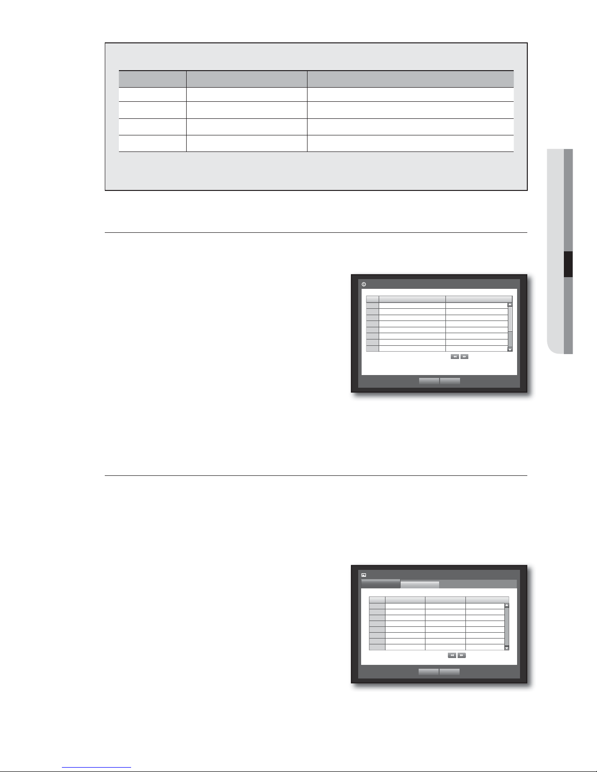
English _53
USING THE DVR
Recording Color Tags
Color Function Description
White No Recording No schedule / event recording
Orange Continuous Scheduled recording only
Blue Event Event recording only
Green Both(Cont&Evnt) Both scheduled / event recordings
Each press of a selected cell will cycle through <No Recording>-<Continuous>-<Event><Both(Cont&Evnt)>.
Event Record Duration
You can set the beginning and ending point of a recording on an event.
Using the mouse may help make setup easier.
Use the up/down buttons () in <Record> window to
move to <Event Record Duration>, and press [ENTER]
button.
Use direction buttons (
◄ ►
) to move to a desired
item, and set the value.
Pre Event : The recording of an event will start at a
pre-determined time prior to the actual occurrence of the event.
If it is set to 5 seconds, the recording begins from 5
seconds before the event.
POST Event : The recording will continue for a
pre-determined time after the actual end of an event.
If it is set to 5 seconds, the recording ends in 5 seconds after an event.
When the event recording duration setup is done, press <OK>.
REC Quality / Resolution
You can set resolution, IPS, and quality of recordings by channel, and by recording type of standard / event.
Setting Standard Recording Properties
You can set each channel’s resolution, quality and IPS for normal recordings.
Using the mouse may help make setup easier.
Use the up/down buttons () in <Record> window to
move to <REC Quality & Resolution>, and press
[ENTER] button.
Select <Standard>.
When the recording setup is done, press <OK>.
Remaining count : If you change the settings of the
resolution and the remaining rate, the frame rate available for
each resolution will be recalculated.
The <Remaining count> will be displayed only for SRD-830DC/
850DC/1610DC/1630DC/1650DC models.
SRD-870DC/1670DC models have no limitations on the remaining rate.
3.
4.
•
•
5.
3.
4.
5.
•
Event Record Duration
OK Cancel
Previous/Next Page
CH Pre Event
b
POST Event
b
1 OFF
b
1 min
b
2 OFF
b
1 min
b
3 OFF
b
1 min
b
4 OFF
b
1 min
b
5 OFF
b
1 min
b
6 OFF
b
1 min
b
7 OFF
b
1 min
b
8 OFF
b
1 min
b
CH Resolution
b
Record Rate bRecord Quality
b
1 CIF(S)
b
7.5ips
b
Level4
b
2 CIF(S)
b
7.5ips
b
Level4
b
3 CIF(S)
b
7.5ips
b
Level4
b
4 CIF(S)
b
7.5ips
b
Level4
b
5 CIF(S)
b
7.5ips
b
Level4
b
6 CIF(S)
b
7.5ips
b
Level4
b
7 CIF(S)
b
7.5ips
b
Level4
b
8 CIF(S)
b
7.5ips
b
Level4
b
REC Quality & Resolution
Standard
Event
Previous/Next Page
OK Cancel
Remaining count : 4CIF(L) : 90 2CIF(M) : 180 CIF(S) : 360
Page 54
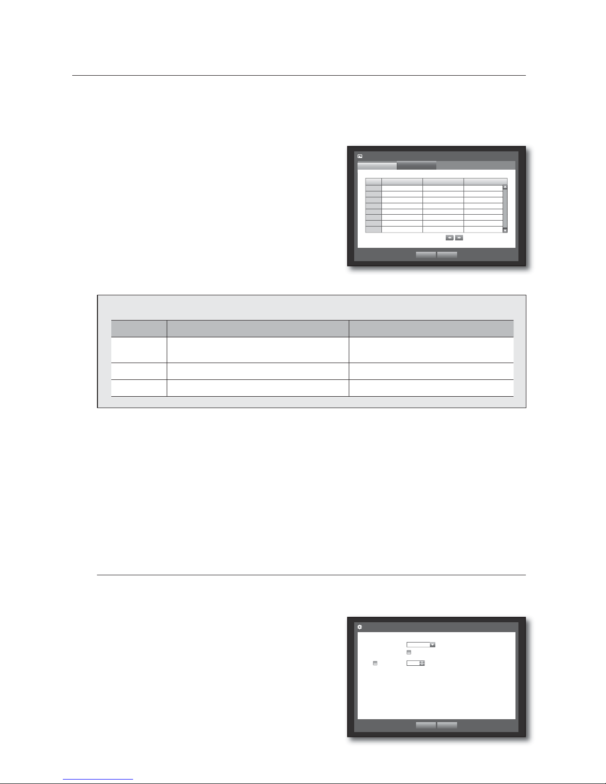
54_ using the DVR
VTJOHUIF%73
Setting Event Recording Properties
You can set each channel’s resolution, quality and IPS for event recordings.
Using the mouse may help make setup easier.
Use the up/down buttons () in <Record> window to
move to <REC Quality & Resolution>, and press
[ENTER] button.
Select <Event>.
Event recording setup window appears.
Use direction buttons (
◄ ►
) to move to a desired
item, and select it.
Resolution : Sets the resolution of the recorded screen.
If you set the resolution to <4CIF(L)>, SRD-850DC/1650DC
support up to 4 channels while SRD-1630DC support up to 2
channels and
SRD-830DC/1610DC support just one channel.
Resolution
Name Resolution Description
CIF(S) NTSC: 352 X 240, PAL: 352 X 288
Samples each half of horizontal and
vertical screen.
2CIF(M) NTSC: 704 X 240, PAL: 704 X 288 Samples half of the horizontal screen.
4CIF(L) NTSC: 704 X 480, PAL: 704 X 576 Samples original screen size.
Record Rate : Image Per Second, means the frames recorded per a second.
Record Quality : Sets the recording quality.
The estimated total remaining count for SRD-830DC/850DC/1610DC/1630DC/1650DC means the total number of
remaining recordings for both standard and event recordings.
You cannot increase the remaining count if the current remaining count has reached zero or there is no available
remaining count from any other page. If this is the case, reduce the remaining count for the current page, or do so
for the same channel on any other page.
When the Event recording setup is done, press <OK>.
Record Option
You can set the recording to stop or overwrite when the HDD is full.
Using the mouse may help make setup easier.
Use the up/down buttons () in <Record> window to
move to <Record Option>, and press [ENTER] button.
Use direction buttons (
◄ ►
) to move to a desired
item, and set the value.
3.
4.
5.
•
•
•
M
6.
3.
4.
Record Option
OK Cancel
x
Disk End Mode Overwrite
Disk End Beep
x
Auto Delete
99 day
CH Resolution
b
Record Rate
b
Record Quality
b
1 CIF(S)
b
7.5ips
b
Level4
b
2 CIF(S)
b
7.5ips
b
Level4
b
3 CIF(S)
b
7.5ips
b
Level4
b
4 CIF(S)
b
7.5ips
b
Level4
b
5 CIF(S)
b
7.5ips
b
Level4
b
6 CIF(S)
b
7.5ips
b
Level4
b
7 CIF(S)
b
7.5ips
b
Level4
b
8 CIF(S)
b
7.5ips
b
Level4
b
REC Quality & Resolution
Standard
Event
Previous/Next Page
OK Cancel
Remaining count : 4CIF(L) : 90 2CIF(M) : 180 CIF(S) : 360
Page 55
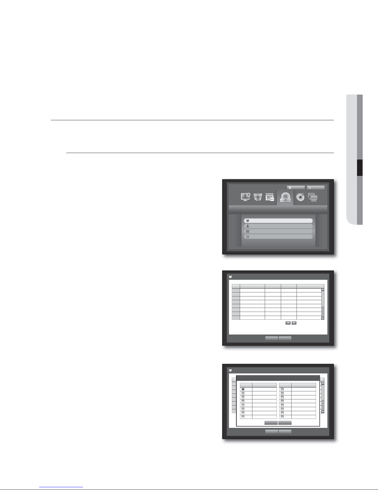
English _55
USING THE DVR
Disk End Mode : If selected <Overwrite>, recording will continue despite the HDD full while overwriting the
oldest.
If selected <Stop>, the recording will stop when the HDD is full.
Disk End Beep : If selected <Stop>, the button is activated.
If you check it, the beep will sound on the disk full and the recording stops.
Auto Delete : If you check it, Record Period setup is activated.
If you setup the auto delete, recorded data only in the configured period are searchable.
When the recording option setup is done, press <OK>.
SETTING THE EVENT
You can set recording options for sensor, motion, and video loss event.
Sensor Detection
You can set the sensor’s operating condition and connected camera, as well as alarm output and its duration.
Using the mouse may help make setup easier.
Press the [MENU] button on the remote control or front
panel.
Use the left/right button (
◄ ►
) to select <Event>.
Event setting menu is selected.
Use the up/down buttons (
) to move to <Sensor
Detection>, and press [ENTER] button.
A window of sensor detection setup appears.
Use direction buttons (
◄ ►
) to move to a desired
item, and set the value.
Sensor Operation : Sets the operation mode of sensors.
-<OFF
> : Sensor does not operate.
-<N.O (Normal Open)
> : Sensor is opened.
If the sensor is closed, it generates alarm.
-<N.C (Normal Close)
> : Sensor is closed.
If the sensor is open by interruption, it generates alarm.
Cam : Select a channel to be connected to the sensor.
If selected camera, “Cam Preset setup” window appears.
Select a channel and setup the preset.
Preset setup can be done in PTZ mode.
•
•
•
5.
1.
2.
3.
4.
•
•
Event
Logout
Exit
Sensor Detection
Motion Detection
Video Loss Detection
Alarm Schedule
Sensor Detection
OK Cancel
Previous/Next Page
Sensor
Sensor Operation
b
Cam bAlarm
b
Duration
b
1 OFF
b
1 None 10 sec
b
2 OFF
b
2 None 10 sec
b
3 OFF
b
3 None 10 sec
b
4 OFF
b
4 None 10 sec
b
5 OFF
b
5 None 10 sec
b
6 OFF
b
6 None 10 sec
b
7 OFF
b
7 None 10 sec
b
8 OFF
b
8 None 10 sec
b
Sensor Detection
OK Cancel
Previous/Next Page
Sensor
Sensor Operation
b
Cam bAlarm
b
Duration
b
1 OFF
b
1 None 10 sec
b
2 OFF
b
2 None 10 sec
b
3 OFF
b
3 None 10 sec
b
4 OFF
b
4 None 10 sec
b
5 OFF
b
5 None 10 sec
b
6 OFF
b
6 None 10 sec
b
7 OFF
b
7 None 10 sec
b
8 OFF
b
8 None 10 sec
b
Cam Preset setup
OK Cancel
CH
b
Preset
1 None
b
2 None
b
3 None
b
4 None
b
5 None
b
6 None
b
7 None
b
8 None
b
CH
b
Preset
9 None
b
10 None
b
11 None
b
12 None
b
13 None
b
14 None
b
15 None
b
16 None
b
Page 56
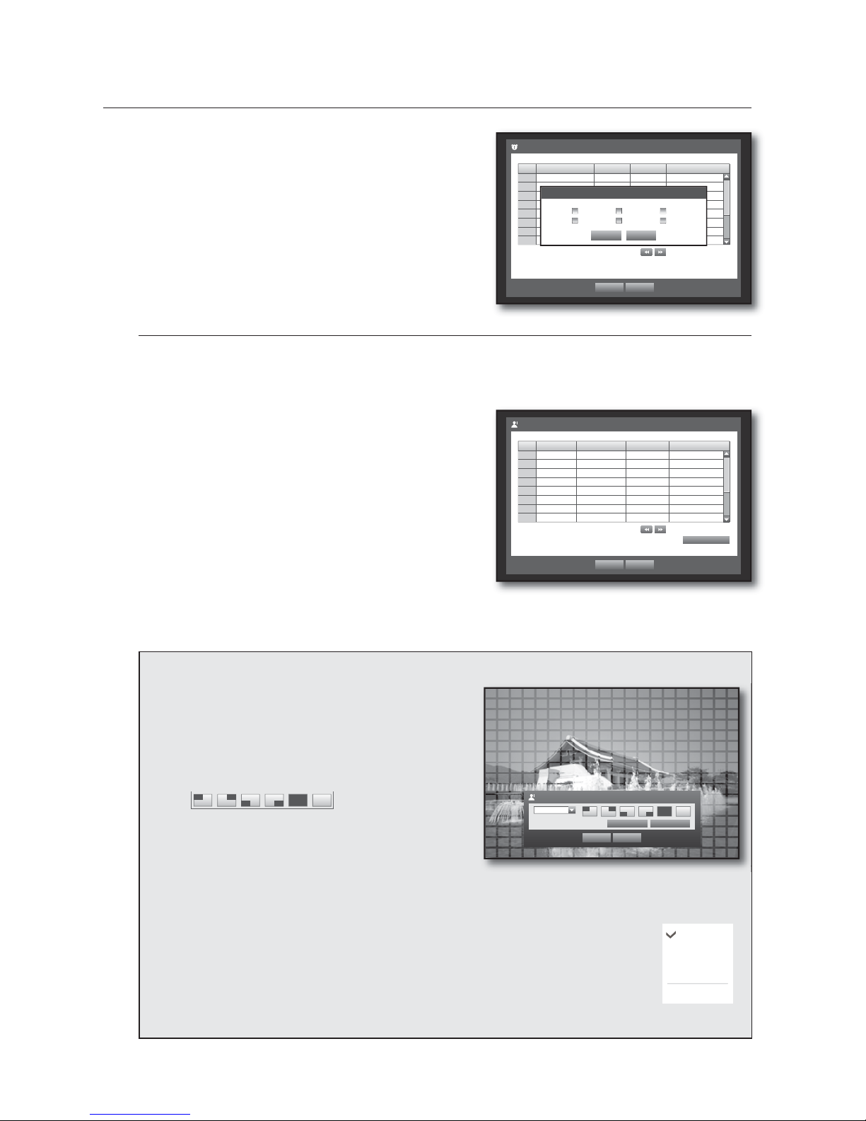
56_ using the DVR
VTJOHUIF%73
Alarm : Sets the alarm output method.
For further information on alarm output, refer to “HDD Alarm >
Alarm”. (Page
47)
Duration : Sets the duration of alarm signal and alarm
sound.
When the sensor detection setup is done, press <OK>.
Motion Detection
You can set target detection region and motion, as well as the alarm signal output.
When the motion detection region is set, it detects motion within the area.
Using the mouse may help make setup easier.
Use the up/down buttons () in <Event> window to
move to <Motion Detection>, and press [ENTER] button.
A window of motion detection area setup appears.
Use direction buttons (
◄ ►
) to move to a desired
item, and set the value.
Mode : Sets whether to activate motion detection.
Sensitivity : Sets the sensitivity level of the motion detection.
Alarm : Sets the alarm output method.
For further information on alarm output, refer to “HDD Alarm >
Alarm”. (Page
47)
Alarm Duration : Sets the duration of alarm signal and alarm
sound.
When the motion detection setup is done, press <OK>.
Setting the Motion Detection Area
{
Select <Motion Region>.
|
When “Motion Region” window appears, select a
channel for detection and set the area of motion
detection.
To set the area in “Motion Region” window
In the “Motion Region” window, select desired region
from < >.
To set the area using <Individual> selection
In the “Motion Region” window, you can select cells
individually by using <Individual>.
•
•
Motion Region
OK Cancel
Apply to All CH
1 CH
Individual
When selected <Individual>, “Motion Region” window disappears and you can select cells one by one.
When the motion area setup is done, press the <Menu> on the screen or the [MENU] button on the
remote control or front panel to display the “Motion Region” window again.
- Select : Selected cell is set to be a part of motion detection area.
- Unselect : Selected cell is removed from the motion detection area.
- Inverse : Unselected cells are set to be the motion detection area.
- Menu : After selecting individual motion areas, move to the “Motion Region” window.
If selected <Apply to All CH>, selected motion area is applied to all channels.
}
When the motion detection setup is done, press <OK>.
•
•
5.
3.
4.
•
•
•
•
5.
Sensor Detection
OK Cancel
Previous/Next Page
Sensor
Sensor Operation
b
Cam bAlarm
b
Duration
b
1 OFF
b
1 None 10 sec
b
2 OFF
b
2 None 10 sec
b
3 OFF
b
3 None 10 sec
b
4 OFF
b
4 None 10 sec
b
5 OFF
b
5 None 10 sec
b
6 OFF
b
6 None 10 sec
b
7 OFF
b
7 None 10 sec
b
8 OFF
b
8 None 10 sec
b
Alarm Setup
OK Cancel
123
4 BEEP All
Motion Detection
OK Cancel
Previous/Next Page
CH Mode
b
Sensitivity bAlarm bAlarm Duration
b
1 OFF
b
Very High
b
None 10 sec
b
2 OFF
b
Very High
b
None 10 sec
b
3 OFF
b
Very High
b
None 10 sec
b
4 OFF
b
Very High
b
None 10 sec
b
5 OFF
b
Very High
b
None 10 sec
b
6 OFF
b
Very High
b
None 10 sec
b
7 OFF
b
Very High
b
None 10 sec
b
8 OFF
b
Very High
b
None 10 sec
b
Motion Region
Select
Unselect
Inverse
Menu
Page 57
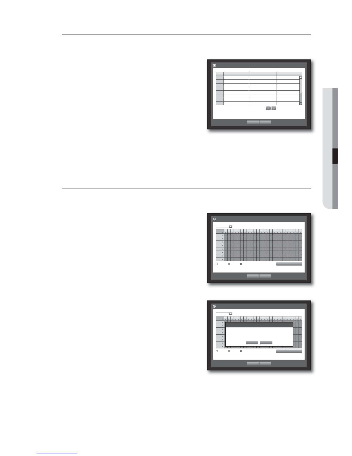
English _57
USING THE DVR
Video Loss Detection
You can set the alarm to be generated on a camera disconnection, which causes a video loss.
Using the mouse may help make setup easier.
Use the up/down buttons () in <Event> window to
move to <Video Loss Detection>, and press [ENTER]
button.
A window of video loss detection area setup appears.
Use direction buttons (
◄ ►
) to move to a desired
item, and set the value.
Video Loss State : Sets whether to activate video loss
detection.
Alarm : Sets the alarm output method.
For further information on alarm output, refer to “HDD Alarm >
Alarm”. (Page 47)
Alarm Duration : Sets the duration of alarm signal and alarm sound.
When the video loss detection setup is done, press <OK>.
Alarm Schedule
You can set the conditions and operating hours for scheduled alarms.
Using the mouse may help make setup easier.
Use the up/down buttons () in <Event> window to
move to <Alarm Schedule>, and press [ENTER] button.
A window of <Alarm Schedule> settings appears.
Alarm : Sets the alarm output method.
For further information on alarm output, refer to “HDD Alarm >
Alarm”. (Page
47)
<ON> : Marked in orange, and always generates alarm on
scheduled time.
<OFF> : Marked in white, no alarm is generated even if an
event occurs.
Event Sync : Marked in Blue, generates alarm only when an event occurs.
Apply to All Alarm : Applies the configured schedule to all
alarms.
When the alarm is generated on the scheduled time, you can
stop the alarm by canceling the schedule.
When the Alarm Schedule setup is done, press <OK>.
3.
4.
•
•
•
5.
3.
4.
5.
•
•
•
•
M
6.
All
0 1 2 3 4 5 6 7 8 9 10 11 12 13 14 15 16 17 18 19 20 21 22 23
Sun
Mon
Tue
Wed
Thu
Fri
Sat
Hol
OFF ON Event Sync
Apply to All Alarm
OK Cancel
Alarm Schedule
Alarm1
Video Loss Detection
OK Cancel
Previous/Next Page
CH Video Loss State
b
Alarm
b
Alarm Duration
b
1 OFF
b
None 10 sec
b
2 OFF
b
None 10 sec
b
3 OFF
b
None 10 sec
b
4 OFF
b
None 10 sec
b
5 OFF
b
None 10 sec
b
6 OFF
b
None 10 sec
b
7 OFF
b
None 10 sec
b
8 OFF
b
None 10 sec
b
All
0 1 2 3 4 5 6 7 8 9 10 11 12 13 14 15 16 17 18 19 20 21 22 23
Sun
Mon
Tue
Wed
Thu
Fri
Sat
Hol
OFF ON Event Sync
Apply to All Alarm
OK Cancel
Alarm Schedule
Alarm1
Apply to All Alarm
OK Cancel
Apply the alarm scheduling to all?
Page 58
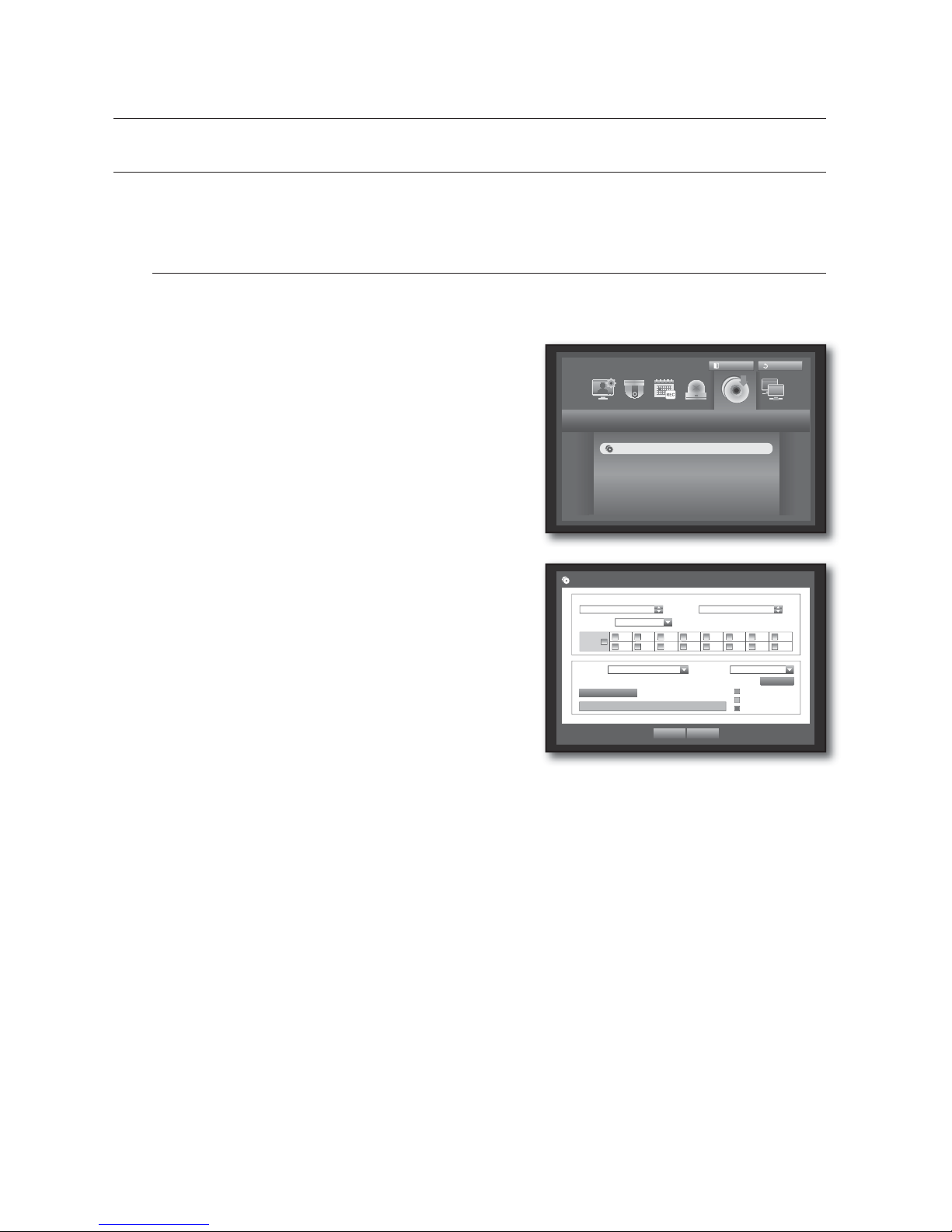
58_ using the DVR
VTJOHUIF%73
BACKUP
You can check the backup device and set the backup schedule by channel or by time.
The product only supports external HDD of USB memory/DVD and USB/SATA type. (Page 98)
Setting the Backup
You can backup the desired data to a connected device.
Using the mouse may help make setup easier.
Press the [MENU] button on the remote control or front
panel.
Use the left/right button (
◄ ►
) to select <Backup>.
Backup menu is selected.
Press the [ENTER] button.
A backup window appears.
You can directly access it from the “Live screen menu”.
(Page
26)
Use direction buttons (
◄ ►
) to move to a desired
item, and set the value.
Backup Range : Sets the <Start> and <End> time for the
backup.
Channel : Sets the channel to backup.
You can select multiple channels.
Device : Select a backup device from the recognized devices.
If the built-in internal CD/DVD or external USB CD/DVD is used for the backup, you can select the format of
recording between AVI and SEC.
Type : Sets the backup data format.
- AVI : Saves the CODEC information provided by the DVR with the recording data, and saved data can be
played back by using external viewers (such as Windows Media Player) on a PC.
- DVR : Saved data can be played back only by the DVR.
- SEC : Saves data in the Samsung’s proprietary format with built-in viewer, which supports immediate
playback on a PC.
Filename : You can set the back file name.
Refer to “Using Virtual Keyboard”. (Page 36)
Check capacity : Shows the size of the selected backup data, used and available capacity of the selected
backup device.
Overlap : Shows a list of overlapping data on a same time according to the number of data.
It appears when one channel has multiple data on a certain time point due to changing of time or time zone
settings, etc.
Refer to time and time zone of “Setting the Date/Time/Language”. (Page 34)
1.
2.
3.
4.
•
•
•
•
•
•
•
Backup
Logout
Exit
Backup
Backup
Used
Free
Check capacity
OK Cancel
Backup
x
Start
x
End
2010-01-01 00:01:06 ~ 2010-01-01 08:25:45
x
Overlap List0
x
Device USB-Storage
x
Type AVI
x
Folder \20100101\
x
Filename 0001
12 34 56 78
9 10 111213141516
ALL
Change
Page 59
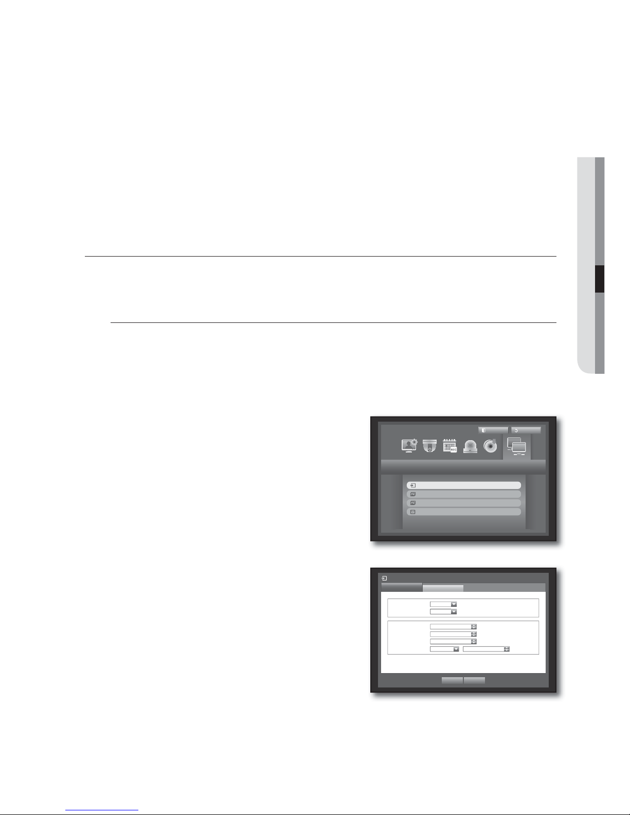
English _59
USING THE DVR
When the backup setup is done, press <OK>.
If no available device is recognized for backup, <OK> button is not activated.
The application may slow down during the backup.
You can switch to the menu screen during the backup in operation, but playback of data is not available.
When a CD/DVD or memory device is used for backup, it is not available to use the full capacity of the media since
the system consumes a part of its capacity.
If a CD or DVD media causes errors, the disc tray opens and closes a several times, and eventually backup process
will fail. In this case, replace the CD/DVD media and try again.
Pressing the <Exit> during the backup will return to the previous menu, while the backup progresses.
NETWORK CONFIGURATION
It provides networked monitoring of Live screen from a remote place, and supports mail forwarding function with
events. You can configure the network environment which enables such functions.
Connection Mode
You can set the network connection route and protocol.
Setting the Connection
Sets the protocol and environment of the network.
Using the mouse may help make setup easier.
Press the [MENU] button on the remote control or front
panel.
Use the left/right button (
◄ ►
) to select <Network>.
Network menu is selected.
Use the up/down buttons (
) to move to <Connection
Mode>, and press [ENTER] button.
Select <Connection>.
A window of connection mode setup appears.
Use direction buttons (
◄ ►
) to move to a desired
item, and set the value.
Connection Mode : Sets the network connection mode.
Bandwidth : Sets the maximum data flow to be transferred.
(Upload speed)
Options will vary depending on the selected connection
mode.
- For <Static IP
>, <Dynamic IP> : Select one from 50
kbps ~ 2Mbps, and Unlimited.
- For <ADSL
>, select one from 50 kbps ~ 600 kbps.
5.
J
M
1.
2.
3.
4.
5.
•
•
Network
Logout
Exit
Connection Mode
DDNS
Live Transfer
Mailing Service
Connection Mode
Connection
Protocol
x
Connection Mode Static IP
x
Bandwidth 2Mbps
OK Cancel
x
IP 192.168. 1.200
x
Gateway 192.168. 1. 1
x
Subnet Mask 255.255.255. 0
x
DNS
Manual 168.126. 63. 1
Page 60
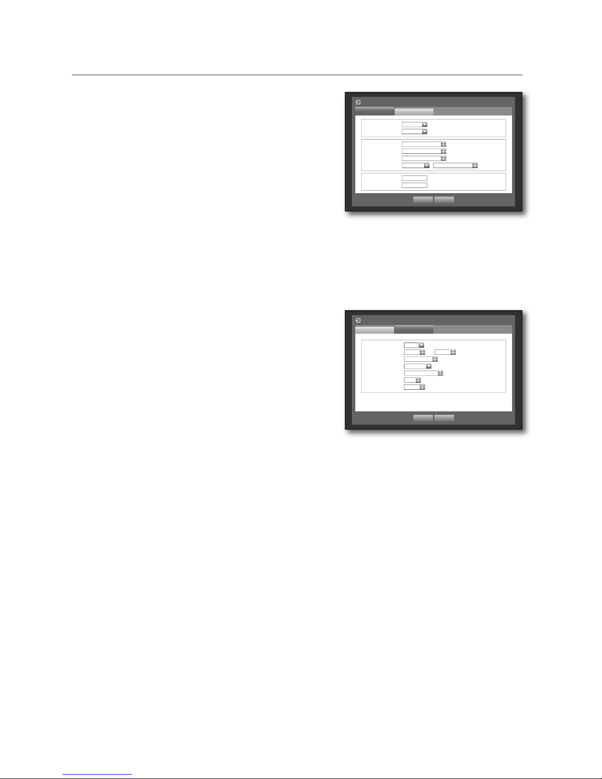
60_ using the DVR
VTJOHUIF%73
IP, Gateway, Subnet Mask, and DNS
- For <Static IP
> : You can directly input IP address,
Gateway, Subnet Mask and DNS.
- For <Dynamic IP
> : IP address, Gateway, and Subnet
Mask are set automatically.
- For <ADSL
> : IP address, Gateway, and Subnet Mask
are set automatically.
User ID, Password : In case you selected ADSL, provide the
“User ID” and its “Password”.
DNS server for <Dynamic IP> and <ADSL> can be set by user only if you selected <Manual>.
When the connection setup is done, press <OK>.
Setting the Protocol
Use the up/down buttons () in <Network> window to
move to <Connection Mode>, and press [ENTER]
button.
Select <Protocol>.
Use direction buttons (
◄ ►
) to move to a desired
item, and set the value.
Protocol Type : Select the protocol type between TCP and
UDP.
If selected UDP, selections of Port (TCP), Port (UDP), and Unicast/
Multicast are activated.
Port (TCP) : Initially, <554~557> is set. It increases / decreases by 4.
- TCP: It has better stability and lower speed when compared to UDP, and recommended for internet
environments.
Port (UDP) : Initially, <8000~8159> is set. It increases / decreases by 160.
- UDP : It has less stability and faster speed when compared to TCP, and recommended for local area
network (LAN) environments.
Unicast/Multicast : Select one between Unicast and Multicast.
If selected Multicast, Multicast IP and TTL are activated.
- Unicast : Transfers data (UDP, TCP) individually to each connecting client.
- Multicast : Multiple client can receive the data (only in UDP) without putting additional traffic load to the
network.
Multicast IP : User can directly input.
TTL : Select from 0 ~ 255. Initial value for the TTL is set to <5>.
Webviewer Port : Enter the port number for the Web Viewer. Initially, it is set to <80>.
When the protocol setup is done, press <OK>.
•
•
M
6.
3.
4.
5.
•
•
•
•
•
•
•
6.
Connection Mode
Connection
Protocol
x
Connection Mode ADSL
x
Bandwidth 600kbps
OK Cancel
x
IP
192.168. 1.200
x
Gateway
192.168. 1. 1
x
Subnet Mask
255.255.255. 0
x
DNS Manual 168.126. 63. 1
x
User ID ID
x
Password
********
Connection Mode
Protocol
Connection
x
Protocol Type TCP
x
Port(TCP) 554 ~
557
x
Port(UDP)
8000 ~ 8159
x
Unicast/Multicast
Unicast
x
Multicast IP
224.126. 63. 1
x
TTL
5
x
Webviewer Port 80
OK Cancel
Page 61
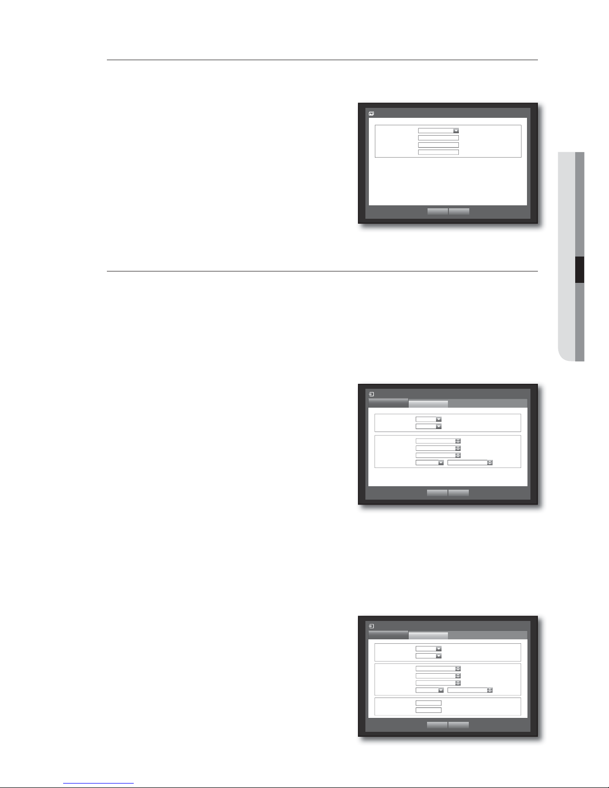
English _61
USING THE DVR
DDNS
You can set the DDNS site for a remote user’s network connection.
Using the mouse may help make setup easier.
Use the up/down buttons () in <Network> window to
move to <DDNS>, and press [ENTER] button.
Use virtual keyboard to enter user inputs.
Refer to “Using Virtual Keyboard”. (Page 36)
If selected <OFF> or <Samsung DDNS>, input fields are
deactivated.
When the DDNS setup is done, press <OK>.
Refer to <DDNS Setting>. (Page 63)
Connecting and Setting the Network
Networking may differ from the connection method, check your environment before setting the connection
mode.
When no router is used
Static IP mode
- Internet connection : Static IP ADSL, leased line, and LAN environments allows connection between the
DVR and remote user.
- DVR Network Settings : Set the <Connection Mode
> in
<Connection> menu of the connected DVR to <Static IP>.
Consult your network manager for IP, Gateway and Subnet Mask.
Dynamic IP (DHCP) mode
- Internet connection : Connect the DVR directly to a cable modem, DHCP ADSL modem or FTTH network.
- DVR Network Settings : Set the <Connection Mode
> in <Connection> menu of the connected DVR to
<Dynamic IP>.
ADSL (PPPoE: ID and password certification)
- Internet connection : An ADSL modem is directly connected to the DVR, where the ADSL connection
requires user ID and password.
- DVR Network Settings : Set the <Connection Mode> in
<Connection> menu of the connected DVR to <ADSL>.
ADSL <User ID> and <Password> should be the same to the
ADSL user information.
If you don’t know the ID and password, consult your ADSL service
provider.
3.
4.
5.
M
•
•
•
OK Cancel
DDNS
x
DDNS Site OFF
x
Host Name
x
User Name
x
User Password
********
Connection Mode
Connection
Protocol
x
Connection Mode Static IP
x
Bandwidth 2Mbps
OK Cancel
x
IP 192.168. 1.200
x
Gateway 192.168. 1. 1
x
Subnet Mask 255.255.255. 0
x
DNS
Manual 168.126. 63. 1
Connection Mode
Connection
Protocol
x
Connection Mode ADSL
x
Bandwidth 600kbps
OK Cancel
x
IP
192.168. 1.200
x
Gateway
192.168. 1. 1
x
Subnet Mask 255.255.255. 0
x
DNS Manual 168.126. 63. 1
x
User ID ID
x
Password
********
Page 62
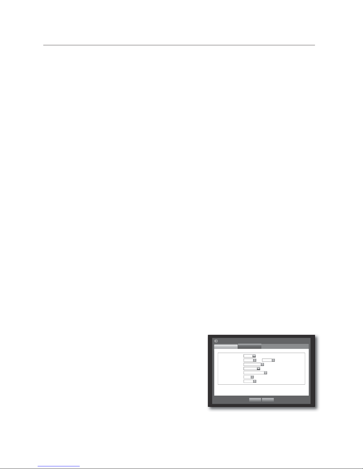
62_ using the DVR
VTJOHUIF%73
When a router is used
To avoid IP address conflict with the DVR's static IP, check followings :
Setting the DVR with a static IP
- Internet connection : You can connect the DVR to a router which is connected to an ADSL/Cable modem or
a router in a Local Area Network (LAN) environment.
Setting the DVR Network
Set the <Connection Mode> in <Connection> menu of the connected DVR to <Static IP>.
Check whether the set IP address is in the static IP range provided by the IP router.
IP, Gateway, and Subnet Mask : Consult your network manager.
Check whether the set IP address is in the static IP range provided by the IP router.
If a DHCP server is configured with starting address (192.168.0.100) and end address (192.168.0.200), you should
set the IP address out of the configured DHCP range (192.168.0.2 ~ 192.168.0.99 and 192.168.0.201 ~
192.168.0.254).
Check the Gateway address and subnet mask are equal to those set in the IP router.
Setting the DHCP IP Address of the IP router
To access the IP router’s configurations, open a web browser on the local PC that is connected to the IP
router and enter the router’s address (ex : http://192.168.1.1).
At this stage, make the local PC's windows network configurations to the below example :
Ex) IP : 192.168.1.2
Subnet Mask : 255.255.255.0
Gateway : 192.168.1.1
- Once connected to the IP router, it prompts with password. While entering nothing to the User Name field,
enter “admin” into the password field and press <OK> to access the router configurations.
- Access the router’s DHCP configuration menu and set its DHCP server activation, and provide the start and
end address.
Set the start address (192.168.0.100) and end address (192.168.0.200).
Above steps may differ from the router devices depending on the manufacturer.
Setting Router’s Port Forwarding
Set the protocol to <TCP>.
External Port Range : Enter the TCP Port set in the
<Port(TCP)> in <Protocol> menu of the connected DVR.
If more than one DVRs are connected to the router, the
TCP port can be different.
Internal PC IP Address : Enter the IP address set to the
<IP> in <Connection> menu of the connected DVR.
Internal Port Range : Set the same to the “External Port
Range”.
Above steps may differ from the router devices depending on the manufacturer.
Port forwarding is required when you want to access the DVR connected to the router from outside of the router’s
network.
J
•
•
1.
2.
J
3.
•
1.
2.
M
•
1.
2.
3.
4.
M
Connection Mode
Protocol
Connection
x
Protocol Type TCP
x
Port(TCP) 554 ~
557
x
Port(UDP)
8000 ~ 8159
x
Unicast/Multicast
Unicast
x
Multicast IP
224.126. 63. 1
x
TTL
5
x
Webviewer Port 80
OK Cancel
Page 63
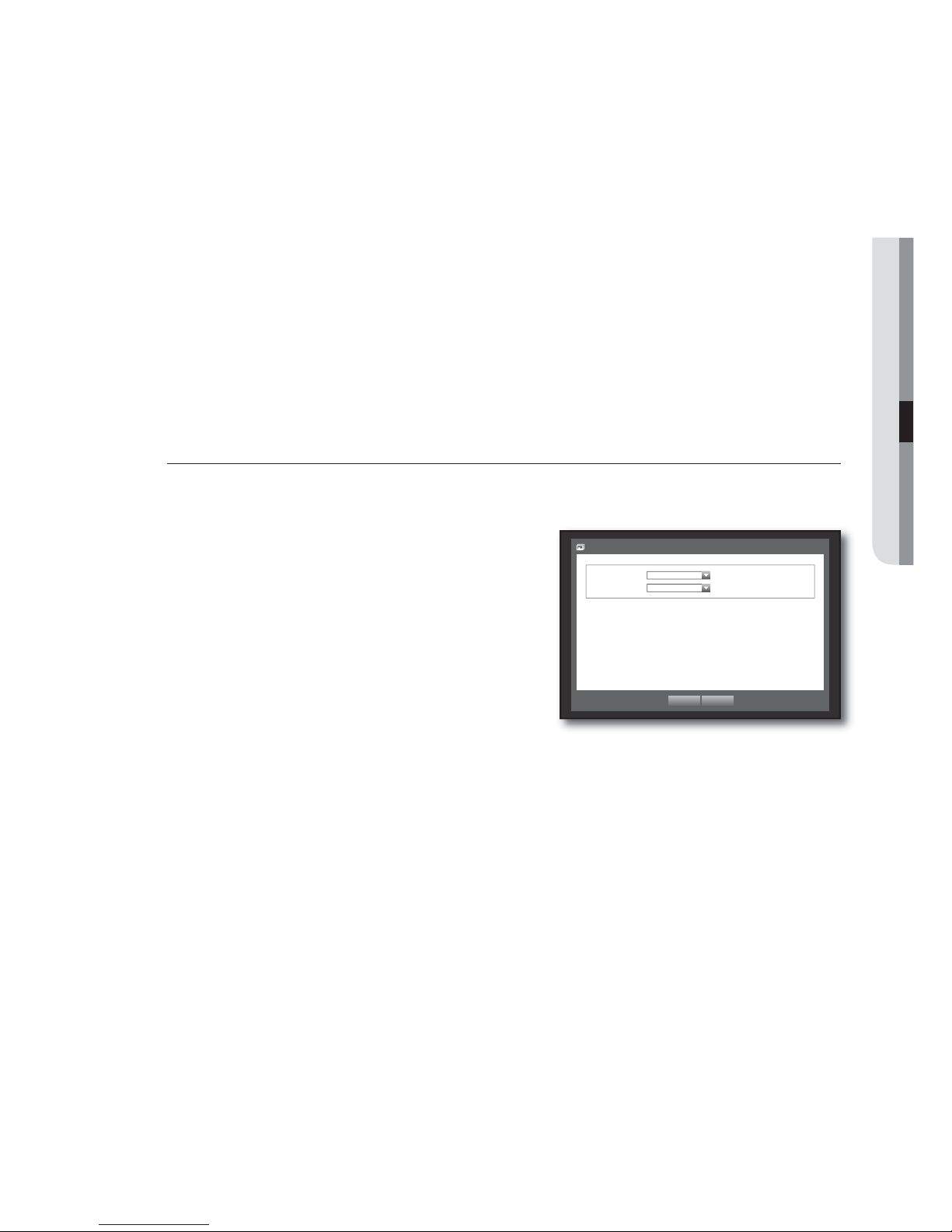
English _63
USING THE DVR
DDNS Setting
DDNS is a short form of Dynamic Domain Naming System.
DNS (Domain Name System) is a service that routes a domain name consisting of user friendly characters
(ex : www.google.com) to an IP address consisting of numbers (64.233.189.104).
DDNS (Dynamic DNS) is a service that registers a domain name and the floating IP address with the DDNS
server so that the domain name can be routed to the IP address even if the IP is changed in a dynamic IP
system.
Setting DDNS in the DVR
Set <Protocol Type> in the <Protocol> menu of the connected DVR to the following :
Ex) Protocol Type : TCP
Port (TCP) : 0554,0555,0556,0557
DDNS Site : Samsung DDNS
DDNS Settings of the Router
Select the corresponding menu for the network transfer protocol of the router.
Live Transfer
Sets the quality of the image that is transferred from the DVR to the network.
Using the mouse may help make setup easier.
In the <Network> setting window, press the up/down
() button to move to <Live Transfer> and press the
[ENTER] button.
The Live Transfer window appears.
Use the direction buttons (
◄ ►
) to move to a desired
item and set the value.
When the live transfer is done, press <OK>.
For the resolution of the live transfer, refer to “Resolution”.
(Page
54)
•
•
3.
4.
5.
Live Transfer
x
Resolution CIF(S)
x
Quality Low
OK Cancel
Page 64
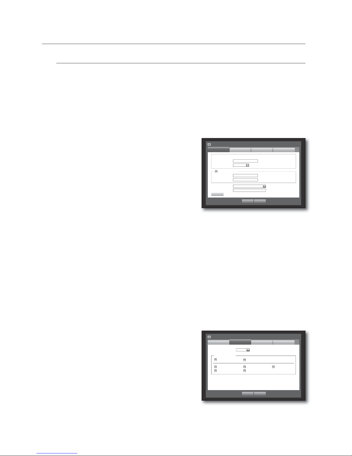
64_ using the DVR
VTJOHUIF%73
Mailing Service
You can send an e-mail to a DVR-registered user at a specific time interval, or if an event occurs.
If an event occurs with a channel where the camera’s video is set to <OFF> or the remaining recording count is set
to <OFF>, only the text notification will be sent to the applicable email address.
SMTP Setting
Sets the SMTP mail server.
Using the mouse may help make setup easier.
In the <Network> setting window, press the up/down
() button to move to <Mailing Service> and press the
[ENTER] button.
Select <SMTP>.
You will see the SMTP setting window.
Use direction buttons (
◄ ►
) to move to a desired item
and set the value.
ServerType : Displays the connected server type.
Server : Enter a server to connect to.
Port : Sets the communication port.
Use Authentication : Check this if the SMTP server uses user authentication.
The account input box will be activated.
User : Enter a user to use authentication when connecting to the SMTP server.
Password : Enter the password of the SMTP server user.
Secure Transfer : Select one from <Never> and <TLS (if available)>.
Sender : Use the virtual keyboard to enter the sender’s e-mail address.
Refer to “Using Virtual Keyboard”. (Page 36)
TEST : Conducts the test on the server settings.
When the SMTP setting is done, press <OK>.
Event Setting
You can set the interval and type of the event that will be sent to the user.
Using the mouse may help make setup easier.
In the <Network> setting window, press the up/down
() button to move to <Mailing Service> and press the
[ENTER] button.
Select <Event>.
Use direction buttons (
◄ ►
) to move to a desired item
and set the value.
Event Interval : Set the event interval.
If a series of events occurs, the e-mail will be sent at the specified
interval, not on each event.
Use Event Transfer : Select an event type to send if an event occurs.
If the selected event occurs, the e-mail will be sent to the group that has the recipient authority.
When the event setting is done, press <OK>.
M
3.
4.
5.
•
•
•
•
•
•
•
•
•
6.
3.
4.
5.
•
•
6.
Mailing Service
SMTP
Event
OK Cancel
Use Authentication
Group Recipient
x
ServerType SMTP mail Server
x
Server
x
Port 25
x
User
x
Password
********
x
Secure Transfer Never
x
Sender ex. [email protected]
TEST
Mailing Service
SMTP
OK Cancel
Recipient
x
Event Interval 10 min
Use Event Transfer
Sensor Motion
Change P/W HDD Info Video Loss
Power On/Off Manual Record
Event
Group
Page 65
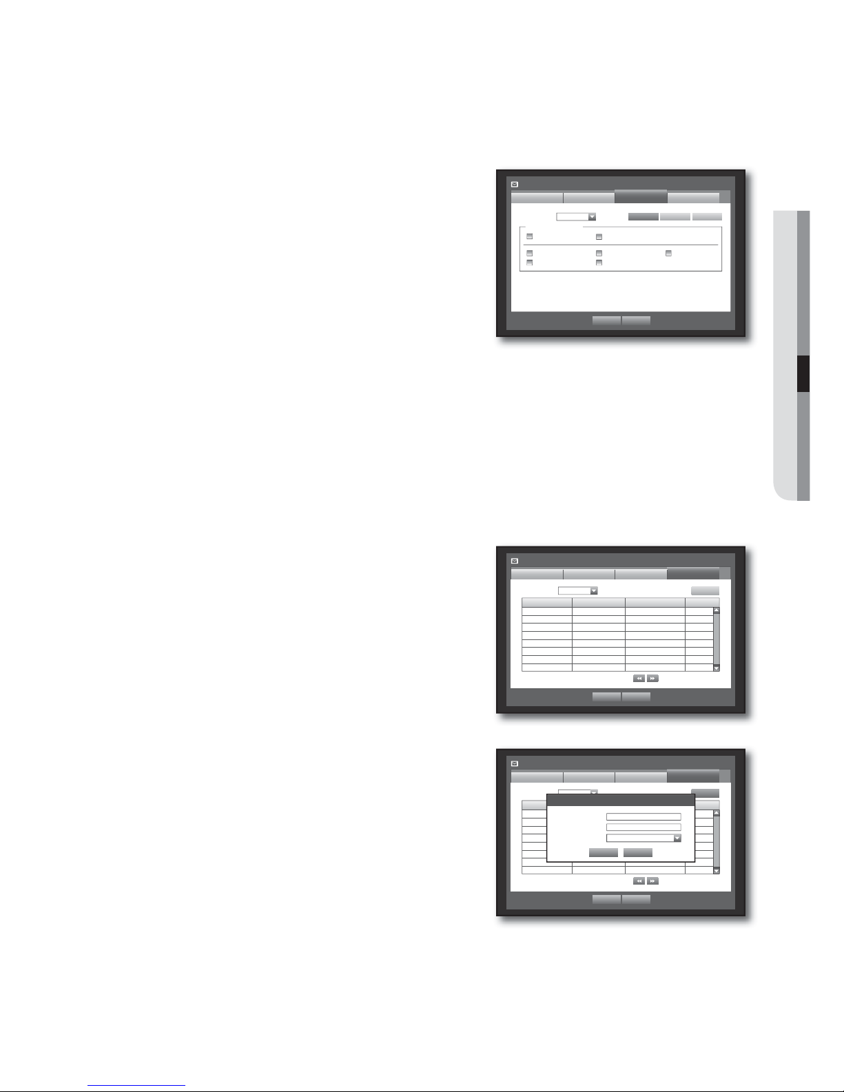
English _65
USING THE DVR
Group Setting
You can set the group to whom the e-mail is sent, and specify the permission for each group.
You can add recipients for each group in the <Recipient> menu item.
The recipient is set separately from the DVR user group.
Using the mouse may help make setup easier.
In the <Network> setting window, press the up/down
(
) button to move to <Mailing Service> and press the
[ENTER] button.
Select <Group>.
Use direction buttons (
◄ ►
) to move to a desired item
and set the value.
Add : Select <Add> and use the virtual keyboard to add a
group.
Refer to “Using Virtual Keyboard”. (Page 36)
Delete : Deletes the selected group.
Rename : You can reset the recipient permission of an existing group.
Recipient Permission : Set the permission of the recipient group.
When the group setting is done, press <OK>.
Recipient Setting
You can add a user to the group or delete him/her from the group, or change the group.
Using the mouse may help make setup easier.
In the <Network> setting window, press the up/down
() button to move to <Mailing Service> and press the
[ENTER] button.
Select <Recipient>.
Use direction buttons (
◄ ►
) to move to a desired item
and set the value.
Add : You can select a recipient name, e-mail address or
group.
You should have created a group in the <Group> menu
item before you can add a user to the group.
Refer to “Using Virtual Keyboard” for input of the user name and
the e-mail address. (Page 36)
When the recipient setting is done, press <OK>.
3.
4.
5.
•
•
•
•
6.
3.
4.
5.
•
6.
Mailing Service
SMTP
OK Cancel
Event Group
Recipient
Group Name e-Mail Address Delete
Add
x
Group
All Group
Previous/Next Page
Mailing Service
Group
SMTP
OK Cancel
Recipient
x
Group
Recipient Permission
Sensor Motion
Change P/W HDD Info Video Loss
Power On/Off Manual Record
Event
Add Delete Rename
Mailing Service
SMTP
OK Cancel
Event Group
Recipient
Group Name e-Mail Address Delete
Add
x
Group ABC
Previous/Next Page
Add recipient
OK Cancel
x
Name
x
Email
x
Select Group ABC
Page 66
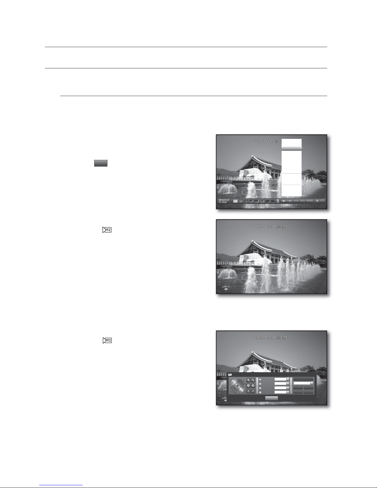
66_ using the DVR
VTJOHUIF%73
CONTROLLING A PTZ DEVICE
The DVR enables you to adjust the settings of a PTZ camera as well as an ordinary one to your preference.
PTZ Device
The PTZ device can be activated only if a channel in connection with the PTZ camera is selected.
Getting started with PTZ
The PTZ camera is available, only if a channel is selected, in the following way :
Using the button on the remote control or the front panel
Select the [PTZ] button on the remote control or the front panel.
Using the launcher menu
Click PTZ <
PTZ
> to display the live launcher.
Using the right-click menu in Live mode
Right-click any area on the screen to display the context menu, and
select <PTZ Control>.
Using icons on the live screen
Click the PTZ <
> icon on the live screen.
The PTZ function is available only if the PTZ camera is
connected so that the PTZ icon is displayed on the screen.
Using the PTZ camera
You can use one camera to perform all functions of PAN, TILT and ZOOM for monitoring multiple places and
set the preset to your preference in a desired mode.
Launch the <PTZ Control> menu.
As the PTZ <
> icon on the bottom right corner turns
yellow, you access the “PTZ Control” mode to display the
“PTZ Control” menu.
Be sure to configure PTZ working environments before
operation, since the PTZ Working(Active) mark can be
appeared to be activated even when PTZ is not operative.
Use direction keys in the launcher menu or use direction
buttons (
◄ ►
) on the remote control or the front panel
to move the target area to record.
PTZ Wheel : Clicking a nearer point to the center will move in
that direction slowly; clicking a farther point from the center will move fast.
Keep clicking left to rotate the lens counter clockwise; keep clicking right to rotate the lens clockwise.
Zoom : You can use the Zoom function of the PTZ camera.
IRIS : Adjusts the intensity of radiation incoming to the iris.
For some cameras, you can use the menu access commands to control the iris.
M
1.
M
2.
•
•
•
PTZ Alarm Freeze
Scene Mode
f
Spot Out
f
PTZ Control
ZOOM
Audio
f
Freeze
Stop Alarm
Record
Play
Search
Backup
Main Menu
Shutdown
Hide Launcher
Logout
PTZ Control CAM01
Select Preset
Save
Rename
Camera Setup
Exit
Auto Pan
Select
Scan
Select
Pattern
Select
Preset
Select
Delete
Delete All
Page 67
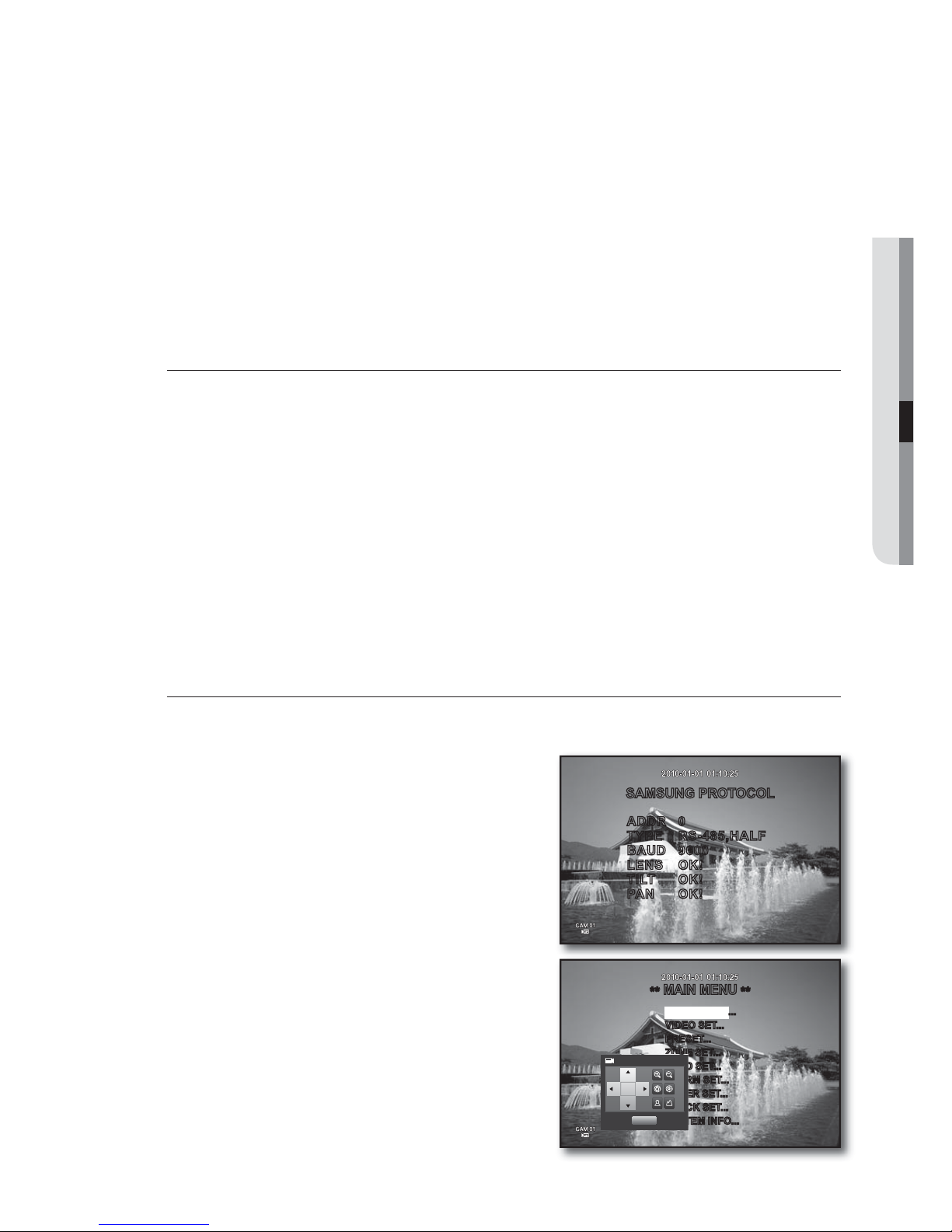
English _67
USING THE DVR
Focus : Enables you to adjust the focus manually.
Auto Pan : The camera automatically runs between the two points that you selected.
This is not available for the coaxial type of communication.
Scan : The camera moves to the preset points in the specified sequence.
If multiple presets are specified, the PTZ camera will automatically move to all of the preset points one at a time.
Pattern : Makes the PTZ camera remember and follow the past route.
For RS-485 communications, functions of Auto Pan, Scan and Pattern are supported by Samsung, Panasonic and Pelco
protocols. However, the menu name and operation may differ depending on the protocol. (Panasonic: Auto Pan, Sequence,
Sort / Pelco: Auto Pan, Frame Scan (or Scan), Pattern)
For the coaxial communications, the operation may differ depending on the protocol.
Before entering the PTZ device control mode, set the values of the PTZ device in the <Setting the PTZ> menu.
(Page 45)
For camera specifications that supports PTZ comtrol depending on communication method, refer to our web site.
Preset Setting
A preset is a set of specific target points of a PTZ camera, and up to 20 presets per a camera can be stored.
Using the mouse may help make setup easier.
In PTZ Control mode, use the direction buttons to adjust the camera in a desired direction.
Select the <Save> key.
The virtual keyboard for inputting the preset will appear.
Refer to “Using Virtual Keyboard”. (Page 36)
Save : You can add and save the preset.
Rename : You can change the settings of the existing presets.
Delete : Deletes the selected preset.
Delete All : Deletes all existing presets.
If you replace the camera of the channel that stores the preset list with a new one, you should reset the preset
accordingly.
Press <OK>.
The preset will be saved as a name that you entered.
Camera Setting
A PTZ camera has its own menu system. Optimize the PTZ camera according to the DVR.
Using the mouse may help make setup easier.
Connect the PTZ camera to the DVR and run the PTZ
camera again to display the camera’s protocol setting
window.
Check the protocol ID of the camera.
In “Device > Setting the PTZ”, enter the PTZ camera ID in the
ID input box of the channel that is connected to the PTZ camera.
(Page 45)
Select <Camera Setup> in the PTZ Control menu.
The camera-specific menu appears.
You can configure the settings of only those cameras that support
the protocols of Samsung, Pelco D/P, AD and Panasonic.
If you are setting Auto Pan or Pattern in the camera menu, press
and hold the appropriate button for a certain time so that the button
operation can be different from that in normal PTZ setting.
•
•
•
•
M
1.
2.
•
•
•
•
M
3.
1.
2.
3.
SAMSUNG PROTOCOL
ADDR 0
TYPE RS-485,HALF
BAUD 9600
LENS OK!
TILT OK!
PAN OK!
**
MAIN MENU
**
CAMERA SET...
VIDEO SET...
PRESET...
ZONE SET...
AUTO SET...
ALARM SET...
OTHER SET...
CLOCK SET...
SYSTEM INFO...
Camera Setup
Exit
Page 68
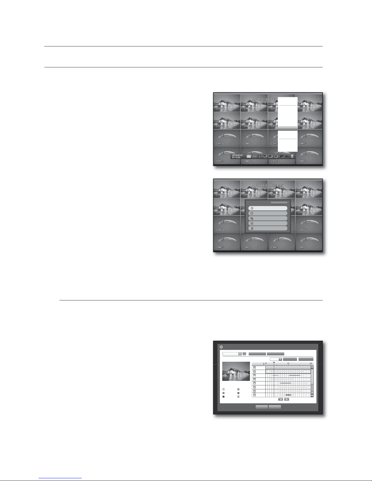
68_ search & play
SEARCH
You can perform the search for recorded data by the time or by the search criteria such as an event.
You can access the <Search> menu directly in Live mode.
In Live mode, right-click any area of the screen.
The Live menu appears.
Select <Search>.
Or, press the [SEARCH] button on the remote control or
the front panel.
The Search menu appears.
If you have not checked “POS USE” in the “Main Menu >
Device > POS Device” menu, the Search menu does not
include the “POS Search” item. (Page 48)
The search can be restricted by the Auto Delete function.
Refer to “Setting the Recording > Record Option”.
(Page 54)
Overlapped data : It only appears if there exists overlapped
data on a certain time, produced due to the change of DVR’s
time setup. The latest data comes first, from <List0>.
It does not appear in <Backup Search>.
Time Search
You can search for recorded data of a desired time.
As the time to display may be different depending on the time zone and the DST standard time, the time of
data recorded in the same time can be displayed differently depending on time zone and DST settings.
Using the mouse may help make setup easier.
Select <Time Search> in the <Search> menu.
Select a date to search.
Refer to “Using the Calendar”. (Page 35)
The record data on the specific date will be listed.
The display bar is different according to the data type.
So check the data type for the color in the left pane.
Use direction buttons (
◄ ►
) to set the search criteria
and press the [ENTER] button.
Go to First : Moves to the earliest date.
Go to Last : Moves to the most recent date.
Time : Enter a time to perform the search or use the up/down button <
>
> to select one.
1.
2.
3.
4.
M
4.
5.
6.
7.
•
•
•
TFBSDIQMBZ
Scene Mode
f
Spot Out
f
Audio Off
Freeze
Stop Alarm
Record
Play
Search
Backup
Main Menu
Shutdown
Hide Launcher
Logout
Time Search
2010-01-01
Play Return
2010/01/01 00:01:17
Standard Schedule
Motion Sensor
V.Loss Etc
Go to First Go to Last
Zoom In Zoom Out
All Data
CAM 01
CAM 02
CAM 03
CAM 04
CAM 05
CAM 06
CAM 07
Previous/Next Page
00:01
Overlapped Data List1
Time Search
Event Search
Backup Search
POS Search
Motion Search
Return
Page 69
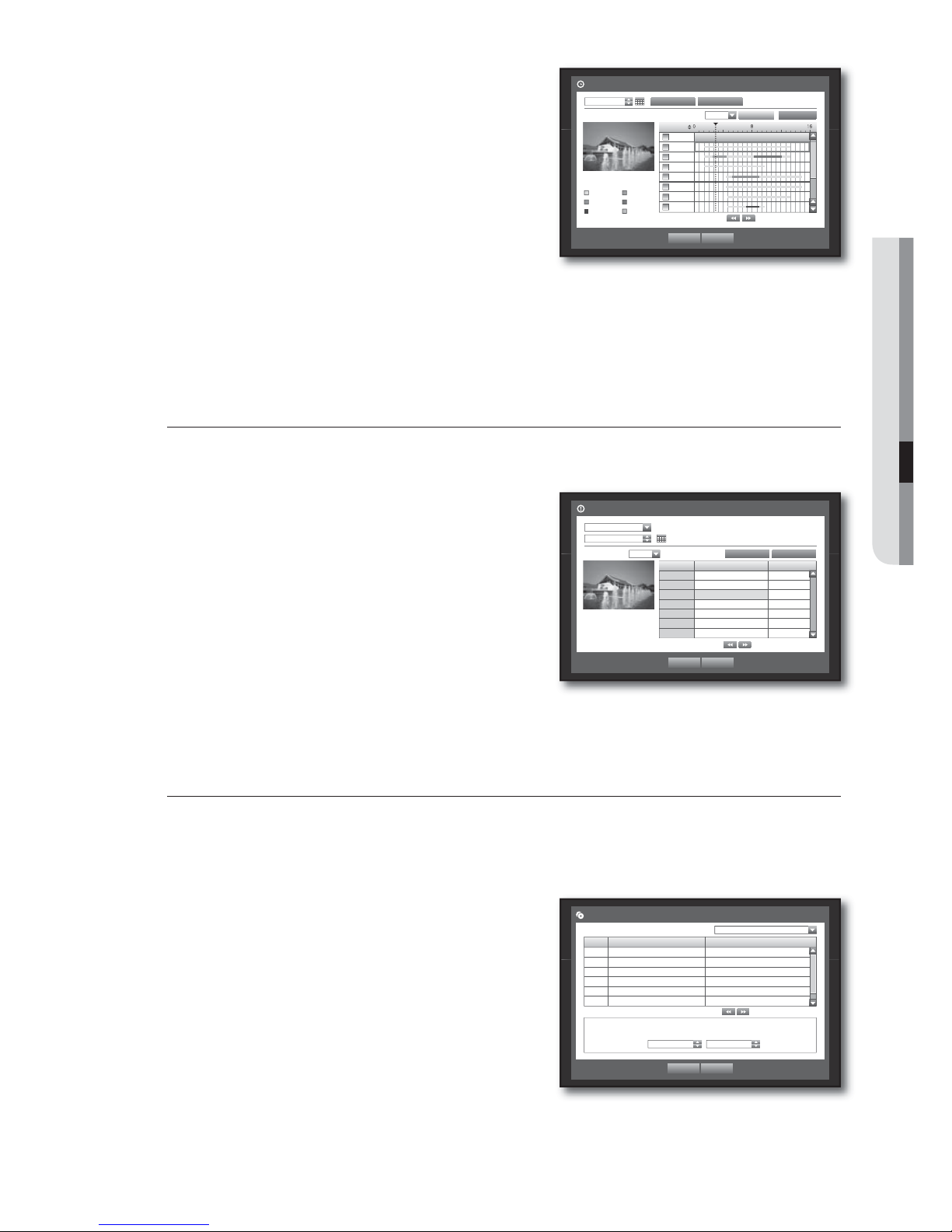
English _69
SEARCH & PLAY
Zoom In : The map enlarges in detail.
It will switch in the sequence of 24 hours - 4 hours - 1 hour
- 5 minutes.
Zoom Out : The map will switch in the reverse order of the
detailed mode above.
It will switch in the sequence of 5 minutes - 1 hour - 4 hours
- 24 hours.
Double-click a desired time to zoom it in/out.
Preview : Click <Channel> and select (click, drag) a time in
<Duration> to display a still image for the portion.
- If the selected channel does not contain any recorded data, it will be marked black.
Select a data item and click <Play>.
The screen switches to the data playback mode.
Event Search
You can search for events by the channel and play them.
Using the mouse may help make setup easier.
Select <Event Search> in the <Search> menu.
Use direction buttons (
◄ ►
) to set the search criteria
and press the [ENTER] button.
All record events on a specific date will be found. (Normal/
Schedule recording included)
Date/Time Preview : If you select a data item in the list, the
still image of the selected data will be displayed in the left
preview pane.
Event : Displays the type of the event that occurred.
Select a data item and click <Play>.
The screen switches to the event data playback mode.
Backup Search
Searches for backup data in the connected backup device.
Only data in the format of DVR is included in the search.
Refer to <Type> in “Backup > Setting the Backup”. (Page 58)
Using the mouse may help make setup easier.
Select <Backup Search> in the <Search> menu.
Use direction buttons (
◄ ►
) to set the search criteria
and press the [ENTER] button.
Record Period : Displays the record period.
Channel : Displays the recorded channel.
Play Start Time : Select a time that you start playing.
Select a data item and click <Play>.
The screen switches to the backup data playback mode.
•
•
M
•
8.
4.
5.
•
•
6.
4.
5.
•
•
•
6.
Backup Search
Play Return
No. Folder Name File Name
1 20100101 16190000
Previous/Next Page
x
File Name 16190000
x
Channel 1
x
Record Period 2010-01-01 01:01:01 - 2010-01-01 01:01:10
x
Play Start Time 2010-01-01 16:30:52
USB:USB2FlashStorage
Time Search
2010-01-01
Play Return
2010/01/01 00:01:17
Standard Schedule
Motion Sensor
V.Loss Etc
Go to First
Go to Last
Zoom In Zoom Out
All Data
CAM 01
CAM 02
CAM 03
CAM 04
CAM 05
CAM 06
CAM 07
Previous/Next Page
00:01
Overlapped Data List1
Event Search
CAM 01
2010-01-01
Play Return
Previous/Next Page
2010/01/01 00:01:22
No. Date/Time Preview Event
3 02:47:54 ~ 02:48:59 Motion
2 00:39:06 ~ 00:40:30 Motion
1 00:01:22 ~ 00:02:28 Motion
Go to First Go to Last
Overlapped Data List1
Page 70
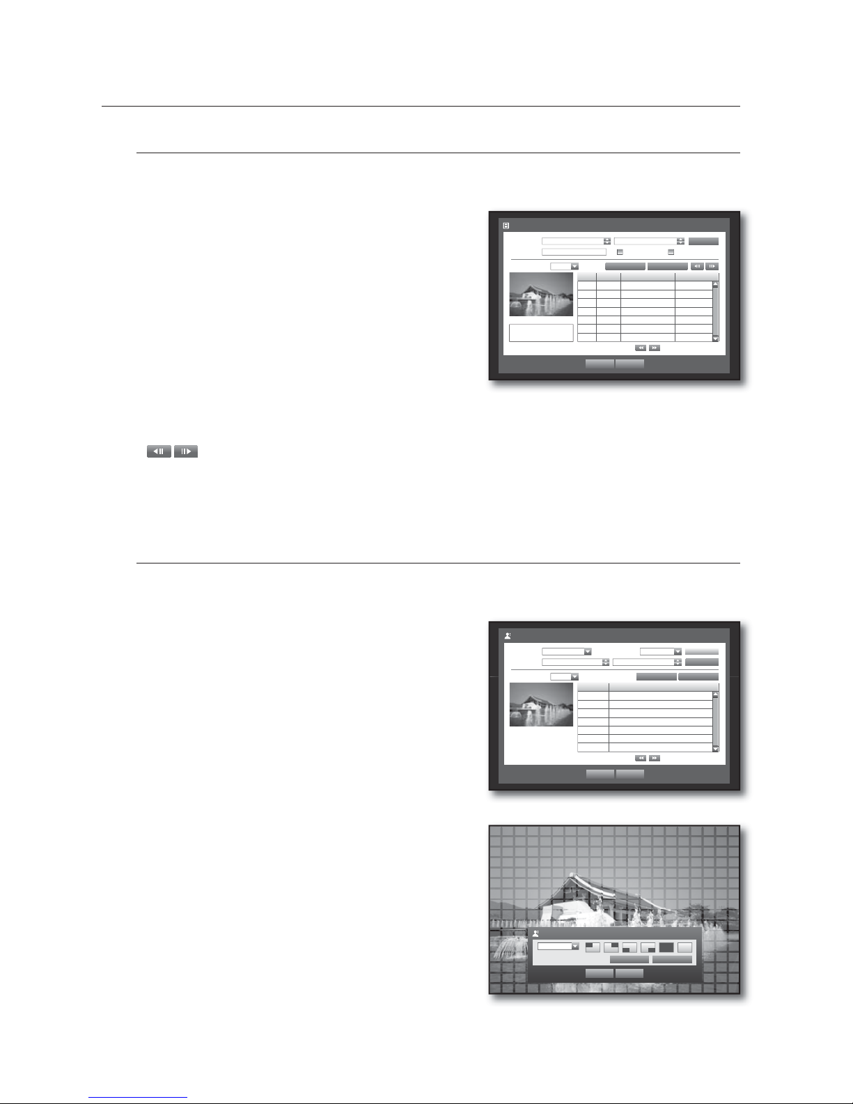
70_ search & play
TFBSDIQMBZ
POS Search
You can search for data in the POS device that is connected to the DVR.
You can use the mouse to select the related items.
Select <POS Search> in the <Search> menu.
Use direction buttons (
◄ ►
) to set the search criteria
and press the [ENTER] button.
You can enter specific text to refine your search.
Keyword : Use the virtual keyboard to enter a keyword.
Search Criteria :
-<Case Sensitive
> : If selected, search will be performed
case-sensitively.
-<Whole Word> : If selected, only the exact matches with
the keyword will be found.
Preview : Select a data item in the list to display the preview image.
Information about the image will be displayed on the bottom of the screen.
: You can use these buttons to accelerate your search if you have a huge list of search results.
Select a data item and click <Play>.
The screen switches to the POS data playback mode.
Motion Search
If a motion is detected in each channel, you can set a desired area to perform the search.
You can use the mouse to select the related items.
Select <Motion Search> in the <Search> menu.
Use direction buttons (
◄ ►
) to set the search criteria
and press the [ENTER] button.
If you set the motion area to <Manual Area>, the <Setup>
button will be activated.
Motion Region : Select an area to perform the search.
- All Area : Searches for all areas of the selected channel.
- Current Area : Searches for the motion area for each
channel specified in “Motion Detection >
Setting the Motion Detection Area”. (Page
56)
- Manual Area : You can set the motion area manually.
Setup : The Setup button will be activated only if you have
set the motion area to Manual. Press this button to display
the area setting window.
Date/Time : The Date/Time will be automatically set by the
hour, and the end time will be automatically set to one hour
later than the start time if it is set.
Preview : Select a data item in the list to display the still
image of the item.
Select a data item and click <Play>.
The screen switches to the motion data playback mode.
4.
5.
•
•
•
•
6.
4.
5.
•
•
•
•
6.
Motion Region
OK Cancel
Apply to All CH
1 CH
Individual
Motion Search
Date/Time 2010-01-01 03:41:18 2010-01-01 05:11:44
Play Return
No. Start Time
7 01:01:30
6 01:01:25
5 01:01:20
4 01:01:15
3 01:01:10
2 01:01:05
1 01:01:01
Previous/Next Page
Search
Channel CAM 01 Motion Region All Area
Setup
2010/01/01 01:01:30
Go to First Go to LastOverlapped Data List1
POS Search
Date/Time 2009-12-25 03:41:18 2010-01-01 03:41:18
Play Return
POS CH Start Date/Time Keyword
1 1 2010-01-01 03:41:15 CHANGE _
1 1 2010-01-01 03:41:15 CASH _
1 1 2010-01-01 03:41:10 CASH _
Previous/Next Page
Search
Keyword Case Sensitive Whole Word
Go to First Go to Last
CHANGE
5.95
2010/01/01 03:41:15
Overlapped Data List1
Page 71
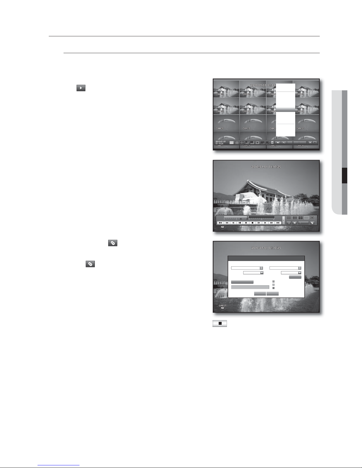
English _71
SEARCH & PLAY
PLAYBACK
Play
You can play data stored in the HDD and backup a desired portion of the data.
Using the mouse may help make setup easier.
In Live mode, click <Play> in the right-click menu or
<
> in the launcher menu, or press the Play button on
the remote control or the front panel.
Use the up/down button (
) to select a menu.
For data search, refer to <Search>. (Page 68)
Select a data item and click <Play> in the Search menu.
The selected data is played and the play launcher appears
on the screen.
If there is an existing data, <Play> will start immediately without
performing the search.
Playback Information : Displays the date and time of the
current data in the top corner.
Backup : Click <
> to set the current time to the start
time of backup; you can specify a backup area using the
mouse (yellow triangle).
Click < > again to set the current time to the end time of
the backup and the “Backup Range” window appears.
- Type : Supports formats of DVR, AVI and SEC.
Refer to a list of formats in “Setting the Backup”.
(Page
58)
- Device : Select a backup device.
- Check Capacity : Enables you to check the capacity of the
selected storage device.
If you want to return to the Live screen in Play mode, click <
> in the launcher menu or press the
[] button on the remote control or the front panel.
1.
2.
3.
•
•
4.
PTZ Alarm Freeze
Scene Mode
f
Spot Out
f
Audio Off
Freeze
Stop Alarm
Record
Play
Search
Backup
Main Menu
Shutdown
Hide Launcher
Logout
Backup 0
Used 0
Free 0
Check capacity
Backup Cancel
Backup Range
x
Start
x
End
2010-01-01 00:01:06 2010-01-01 08:25:45
x
Device USB-Storage x Type DVR
x
Folder \20100101\ x Filename 0001
Change
REC
Page 72
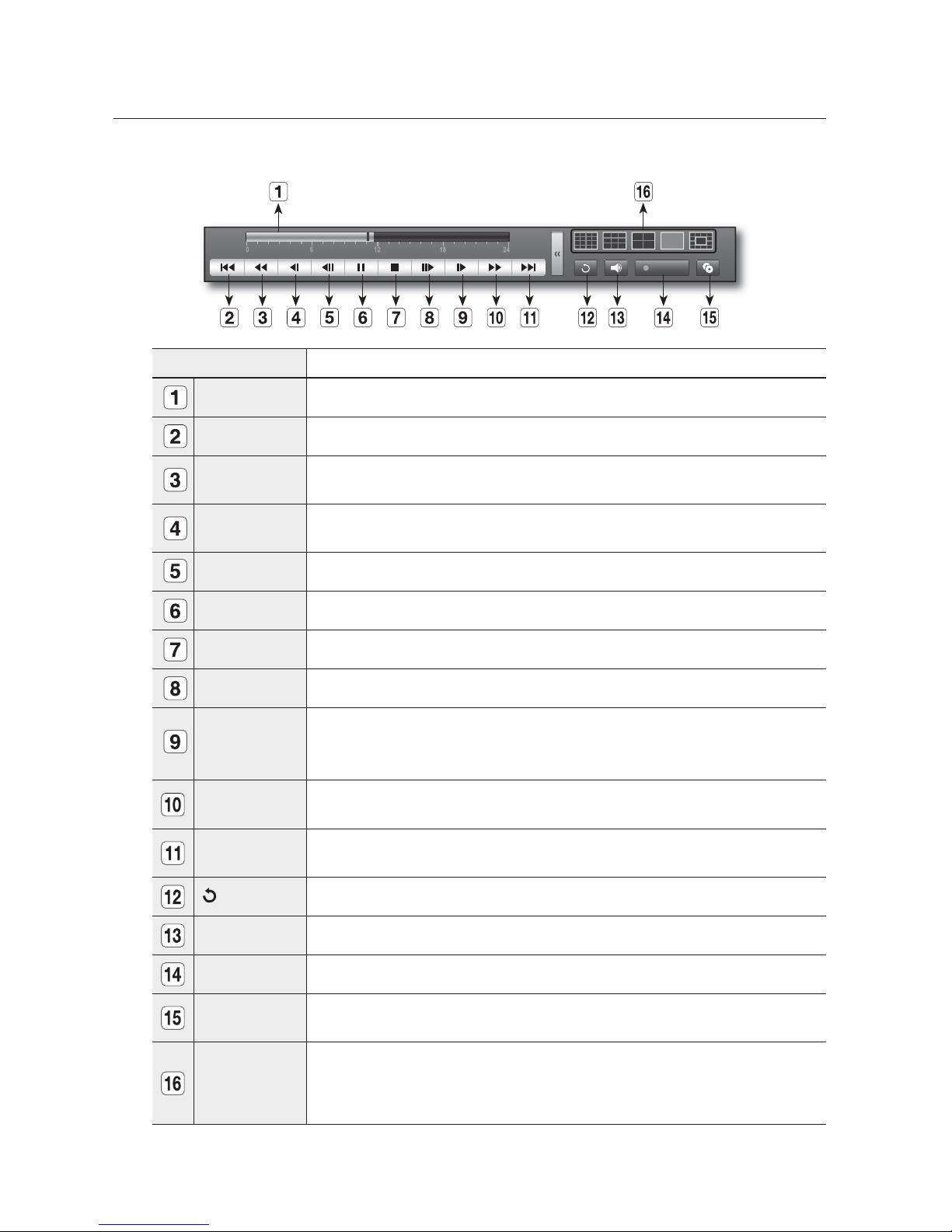
72_ search & play
TFBSDIQMBZ
Using the Playback Button
Part Names Functions
Play Timeline Indicates the current playback point, and can be used to move.
Skip Backward Moves backward by unit time.
Backward Fast
Play
Used for quick backward search while in Play. (-x2, -x4, -x8, -x16, -x32, -x64)
Backward Slow
Play
Used for backward frame-by-frame search while in PAUSE.
Step Backward Moves backward by 1 frame.
Pause
Stop Stops playback and moves to the live screen.
Step Forward Moves forward by 1 frame.
Forward Slow
Play
You can play up to 4 channels in real time.
In a split mode, the real time playback may not be supported, depending on the record
quality, resolution and number of channels. And some frame rates may be supported.
Forward Fast
Play
Used for quick forward playback. (x2, x4, x8, x16, x32, x64)
Skip Forward Moves forward by unit time.
Return to the previous.
Audio Sets Audio ON/OFF.
REC Records all channels in Live mode.
Partial Backup
Begins backup of the selected section of the video being played, with the specified starting/
ending point.
Mode Switch
Select a desired play mode or press the [MODE] button to switch the mode in the sequence of
16-split, 9-split, 4-split, 1-split and 13-split.
The grey area in the center of the 13-split mode plays the Live channel.
The default channel of the Live mode is CH1, which can be changed later.
REC
Page 73
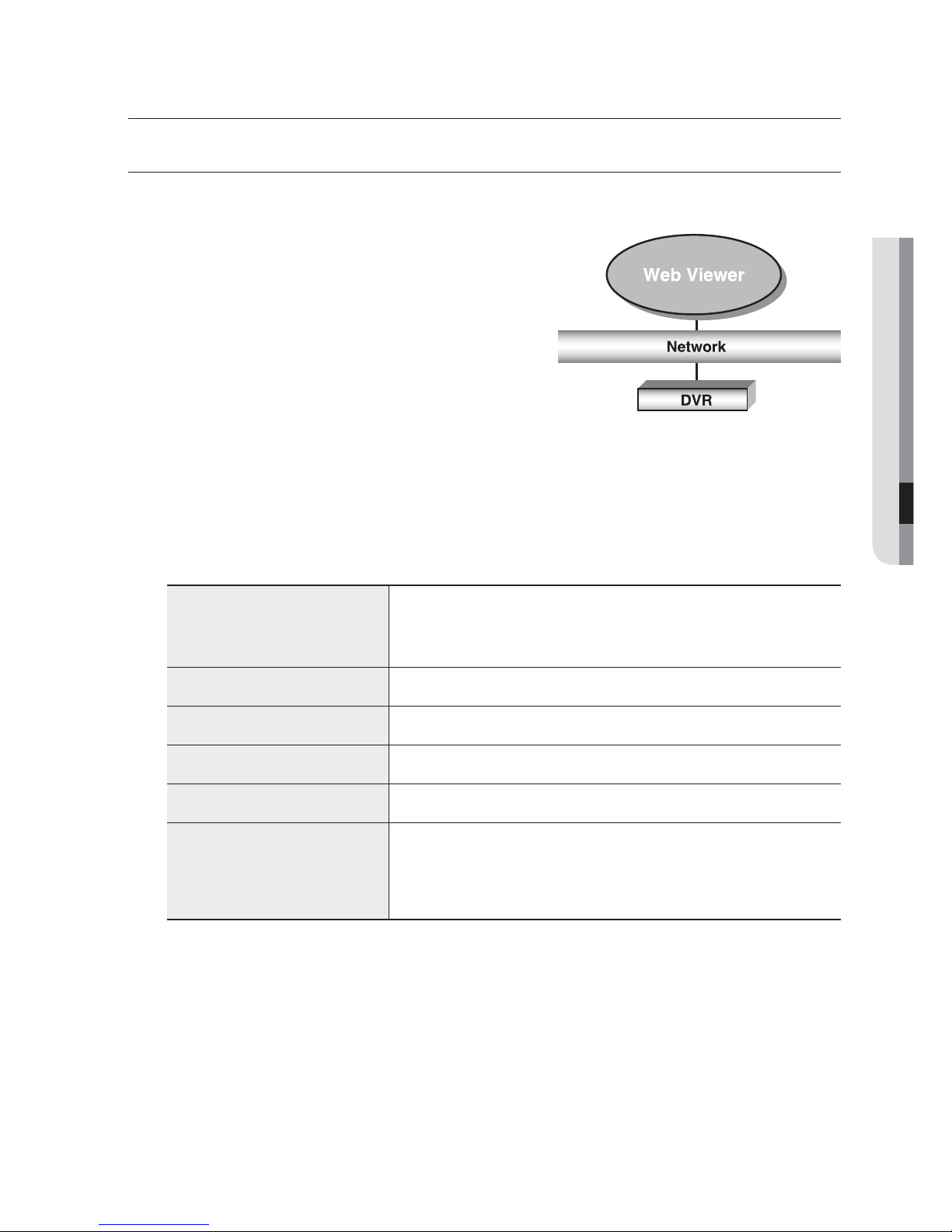
English _73
WEB VIEWER
INTRODUCING WEB VIEWER
What is Web Viewer?
Web Viewer allows remote access to your DVRs. You have
access to live video, archived video, PTZ control (if configured),
etc.
PRODUCT FEATURES
Remote access from a standard browser
Supports PTZ camera controls
Supports 1, 4, 8, 16 camera viewing formats (maximum of
16 cameras in the list).
Gets JPEG format images to print and save to “Print or Save
JPEG format images”.
Record video in AVI format-compatible with popular media players. (needed the Xvid codec)
SYSTEM REQUIREMENTS
The following lists the minimum suggested hardware and operating system requirements needed to run the
Web Viewer.
OS
Windows XP Professional
Windows 2000
Windows Vista Home Basic /Premium
Windows 7
Web Browser Internet Explorer 6.0.2900.2180 or higher
CPU Intel Pentium 4. 2 GHz
Memory 512 MB
Monitor High Color 16-bit 1024 x 768
HDD
50 MB(Installation space required)
* Additional HDD space required for recording.
Recorded file size will vary depending on recording quality settings.
•
•
•
•
•
XFCWJFXFS
Page 74
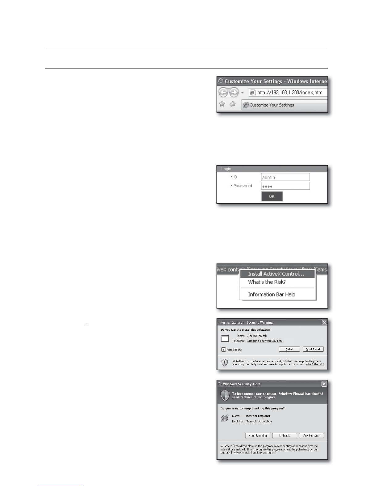
74_ web viewer
XFCWJFXFS
CONNECTING WEB VIEWER
Open your web browser and type the IP address or URL
of DVR into the URL address box.
The basic URL of the DVR is as following in case of MAC
address :
00-00-F0-ab-cd-ef : nabcdef.websamsung.net
00-16-6c-ab-cd-ef : mabcdef.websamsung.net
00-68-36-ab-cd-ef : pabcdef.websamsung.net
00-09-18-ab-cd-ef : iabcdef.websamsung.net
You can also use registered URL which setups up in the Setup menu of your DVR.
Set the Admin ID and password same to those of the DVR
Admin.
For general users, enter the DVR user ID and password.
It allows up to 10 simultaneous access including the Admin
and general users.
It does not allow multiple login of the Admin user.
Initial password of the Admin user is set to “4321”.
Password of the Admin and general users can be changed in <Permission Management> menu of the DVR.
Normal users should have set <Viewer> under <Permission Management> to “Use” before connecting to the
Web Viewer. (Page
39)
All settings are applied by the DVR’s settings.
Click <Install ActiveX Control…>.
Click <Install>.
You may have “Windows Security Alert” that attempts to
block this with the Windows Firewall. In that case, click
<Unblock> to start Web Viewer.
Installation is complete.
Now you can see the main screen of Live Viewer.
1.
M
2.
M
3.
4.
5.
6.
Page 75
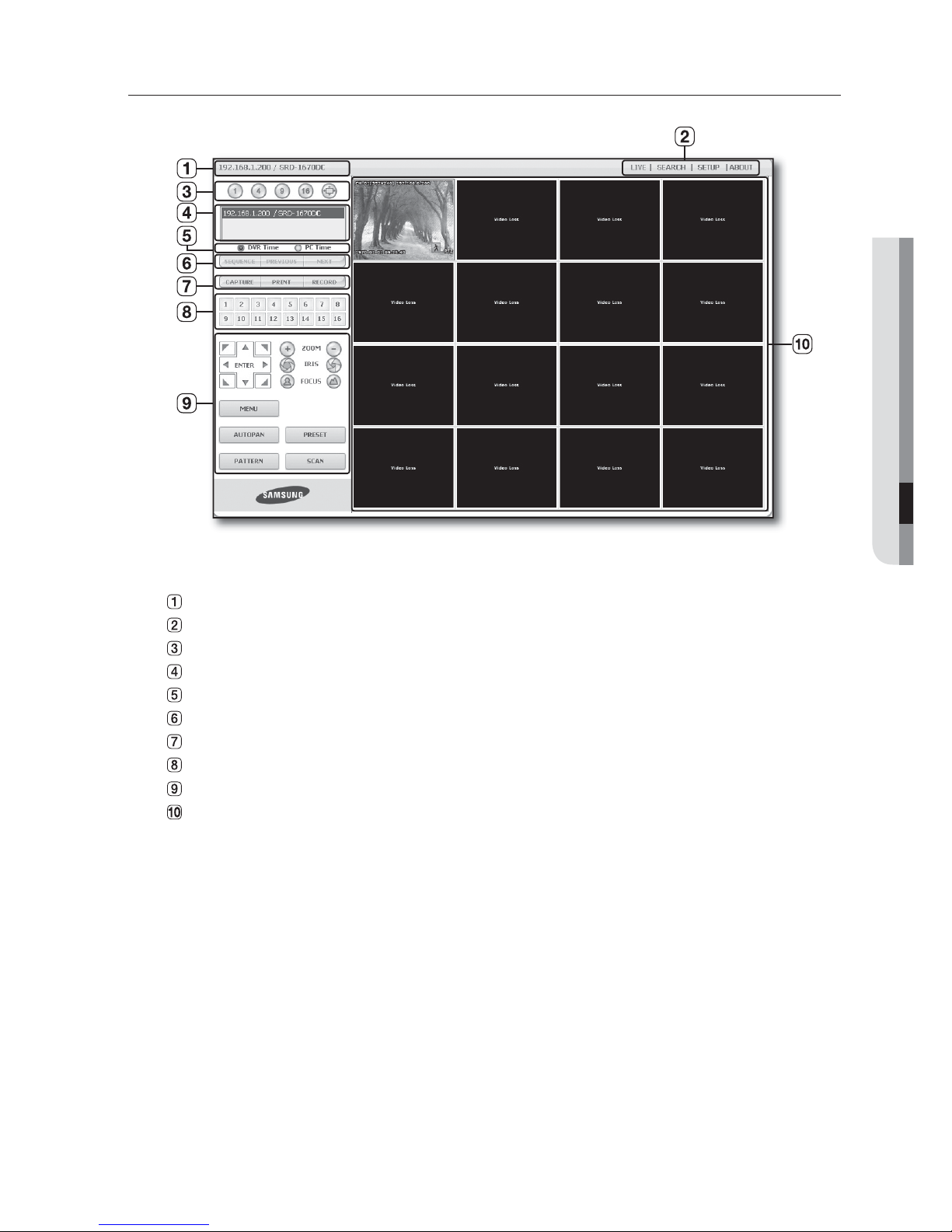
English _75
WEB VIEWER
USING LIVE VIEWER
The Live Viewer screen consists of following :
This displays the IP address and the model name of the connected DVR.
These menus consist of <LIVE>, <SEARCH>, <SETUP>, <ABOUT>.
These buttons are used for the screen split and full screen mode.
Shows the IP address and model name of the connected DVR.
Select <DVR Time> or <PC Time> for the OSD time information display setting of the Live Viewer.
These buttons are used for sequence and changing the screen channel.
These buttons are used for capture, print, and save the image.
Shows the channel of the connected DVR.
These buttons are used for PTZ related functions.
This displays the screen for connected camera with DVR.
The resolution is set to 1024X768 pixels.
The initial split-screen mode is set according to the number of channels connected to DVR. You can change the
split-screen mode by clicking buttons for split-screen modes.
M
Page 76
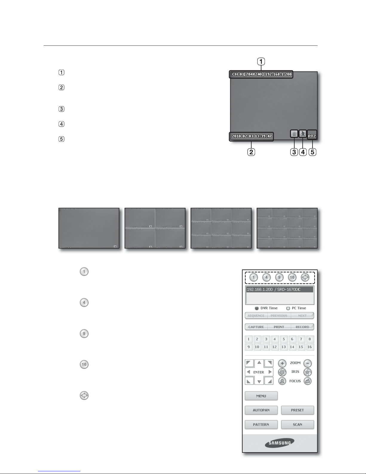
76_ web viewer
XFCWJFXFS
OSD INFORMATION DISPLAY
The channel number, video size, and IP address of the connected
DVR are displayed.
The current date and time will be displayed according to the
selected time information display setting <DVR Time> or <PC
Time
>.
Alarm icon appears when alarm is issued.
It disappears when pressed the [ALARM] button of the DVR.
Motion icon appears when motion is detected.
It disappears when pressed the [ALARM] button of the DVR.
It displays whether the PTZ controls are active.
If you have set PTZ cameras for the DVR, “PTZ” is displayed on the
screen. Select a PTZ camera channel and use the [PTZ] button for camera control.
Power PTZ is not supported for coaxial communications.
SPLIT-SCREEN
You can change the split mode by clicking each number icon.
Click <
> button.
The screen displays the selected camera connected to the DVR in
“SINGLE MODE”.
Click <
> button.
The screen displays the selected camera connected to the DVR in
“QUAD MODE”.
Click <
> button.
The screen displays the selected camera connected to the DVR in
“NINE MODE”.
Click <
> button.
The screen displays the selected camera connected to the DVR in
“SIXTEEN MODE”.
Click <
> button.
The screen displays the selected camera connected to the DVR in
“FULL SCREEN MODE”.
Double clicking on the screen or pressing any button of the keyboard
returns to the previous mode.
M
•
•
•
•
•
SINGLE MODE QUAD MODE NINE MODE SIXTEEN MODE
Page 77
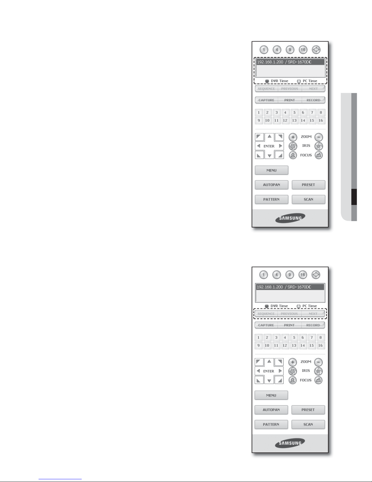
English _77
WEB VIEWER
CONNECTED DVR
This displays the IP address and the status of the connecting DVR.
Connection failure message
No Response : Appears when the DVR does not respond.
Access Denied : Appears when the maximum number of users is exceeded.
The number of simultaneous connections are limited to 10.
Setting the display of the OSD time information
Select <DVR Time> or <PC Time> for the OSD time information display
setting.
DVR Time
: Based on the time of the connected DVR
PC Time
: Based on the time of the PC currently running the Web Viewer.
CHANGING THE LIVE SCREEN MODE
16-split mode does not support “SEQUENCE”, “PREVIOUS” and “NEXT”.
SEQUENCE : When this button is clicked, screens are switched at a
preset interval.
In SINGLE MODE, the channel numbers are sequentially switched from
1 to 16.
In QUAD MODE, the screens are changed like 1st 4 channels (1~4)
2nd 4 channels (5~8) 3rd 4 channels (9~12) 4th 4 channels
(13~16).
In NINE MODE, the screens are changed from 9 channels (1~9) to 7
channels (10~16).
In SIXTEEN MODE, the screen refreshes at the preset interval.
Preset interval (10 seconds)
PREVIOUS : When this button is clicked, the previous screen appears.
In SINGLE MODE, the channel numbers are switched in reverse order.
In QUAD MODE, the screens are changed like 1st 4 channels (1~4)
2nd 4 channels (13~16) 3rd 4 channels (9~12) 4th 4 channels (5~8).
In NINE MODE, the screens are changed from 9 channels (1~9) to
7 channels (10~16).
In SIXTEEN MODE, the screen is refreshed.
M
•
•
•
•
Page 78
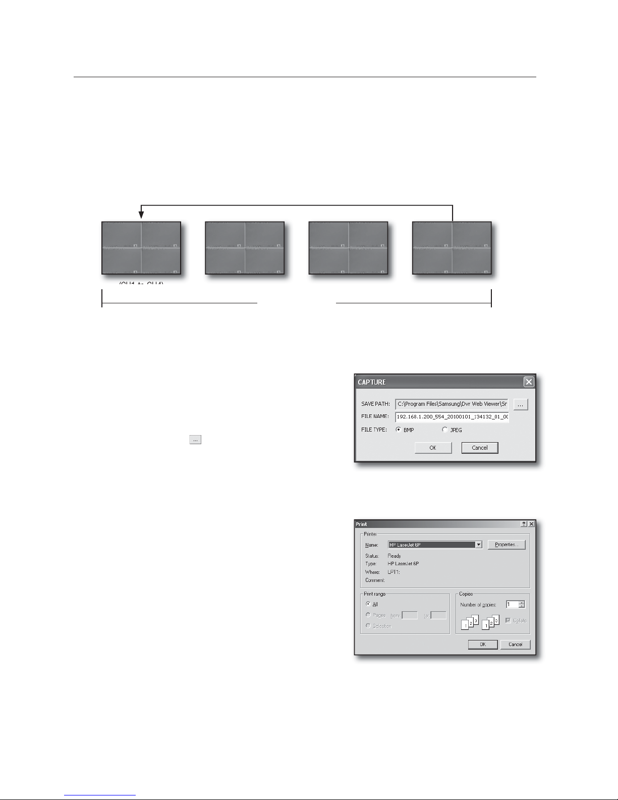
78_ web viewer
XFCWJFXFS
NEXT : When this button is clicked, the next screen appears.
In SINGLE MODE, the channel numbers are sequentially switched from 1 to 16.
In QUAD MODE, the screens are changed like 1st 4 channels (1~4) 2nd 4 channels (5~8)
3rd 4 channels (9~12) 4th 4 channels (13~16).
In NINE MODE, the screens are changed from 9 channels (1~9) to 7 channels (10~16).
In SIXTEEN MODE, the screen is refreshed.
If 16-channel DVR is connected, clicking “NEXT” in QUAD MODE is to change the screen as shown in the picture.
SAVING THE LIVE SCREEN ON THE PC
CAPTURE : Saves the current screen into a BMP or JPEG
file.
The default saving path is “C:\Program Files\Samsung\Dvr
Web Viewer\SnapShot\Live”. To change the saving path, click
<SAVE PATH ( )> button and then select the path you
want. For Windows Vista or 7, the saving path is “C:\users\
(user ID)\AppData\LocalLow\Samsung\DVR Web Viewer\
Snapshot\” by default, which cannot be modified.
The file is automatically named as following : “IP address_Port number_YYYYMMDD_camera number_index”
Ex) 192.168.1.200_554_20100101_134132_01_00
PRINT : Prints out the selected screen out of the currently
displayed live screens. It also prints the IP address, time,
camera number and the current event status together.
•
•
M
•
(CH1 to CH4)
16-channel DVR
(CH5 to CH8) (CH9 to CH12) (CH13 to CH16)
Page 79
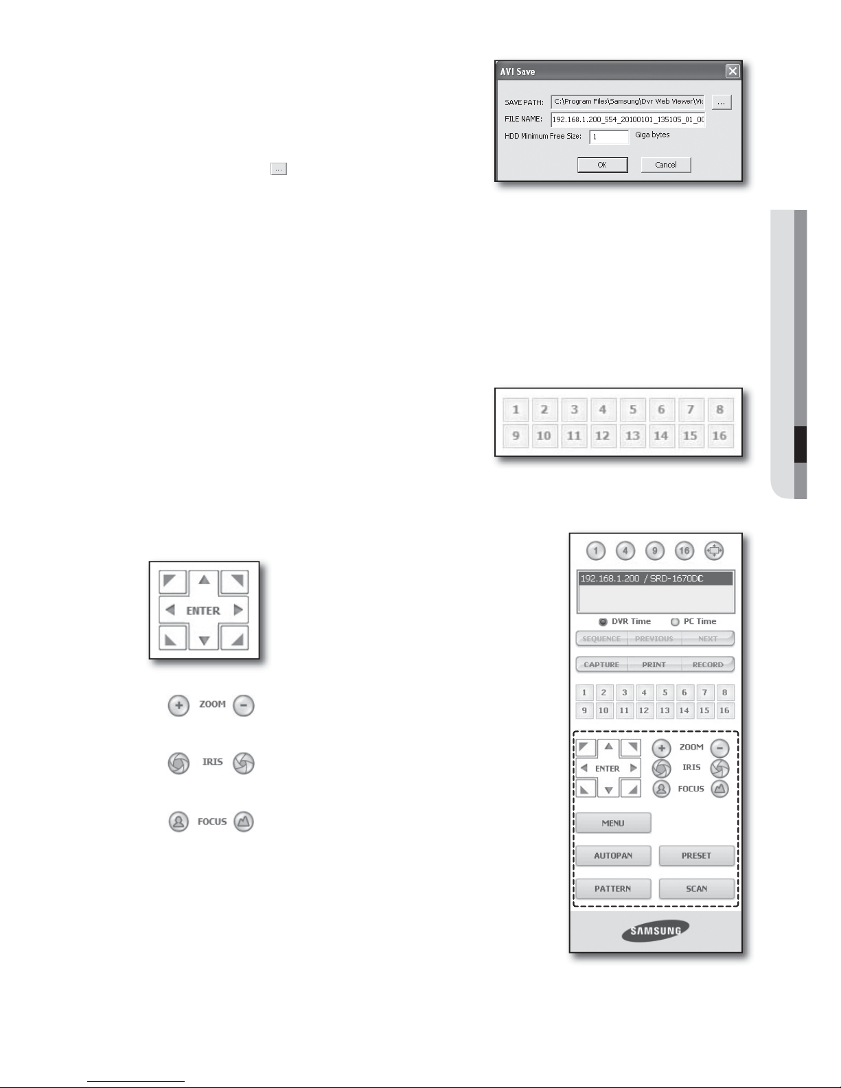
English _79
WEB VIEWER
RECORD : Saves the current image on the screen and
saves it as a avi video file.
To record it, it is required at least 1GB of available space.
The default saving path is “C:\Program Files\Samsung\Dvr
Web Viewer\VideoClip\Live”. To change the saving path, click
<SAVE PATH (
)> button and then select the path you
want. For Windows Vista or 7, the saving path is “C:\users\
(user ID)\AppData\Local-Low\Samsung\DVR Web Viewer\VideoClip\”
and it cannot be modified.
The file is automatically named as following : “IP address_Port number_YYYYMMDD_camera number_index”
Ex) 192.168.1.200_554_20100101_135105_01_00
For AVI Save, you need the Xvid codec for playing saved files.
HDD Minimum Free Size : During the recording, if there is no more capacity available in the HDD than set free space
will prompt with a popup message : “Cannot record due to insufficient disc space in the HDD”.
CHANGING THE LIVE SCREEN CHANNEL
Blue numbers : Indicates that the current channel is
connected to a camera.
Gray numbers : Indicates that the current channel is not
connected to any camera.
USING PTZ CAMERA
Click the direction buttons to control the camera.
<
>
You can zoom in or out an image by using the ZOOM button.
<
>
You can adjust the entering light amount by using the IRIS button.
<
>
You can adjust the focus by using the FOCUS button.
•
M
•
•
•
•
•
Page 80
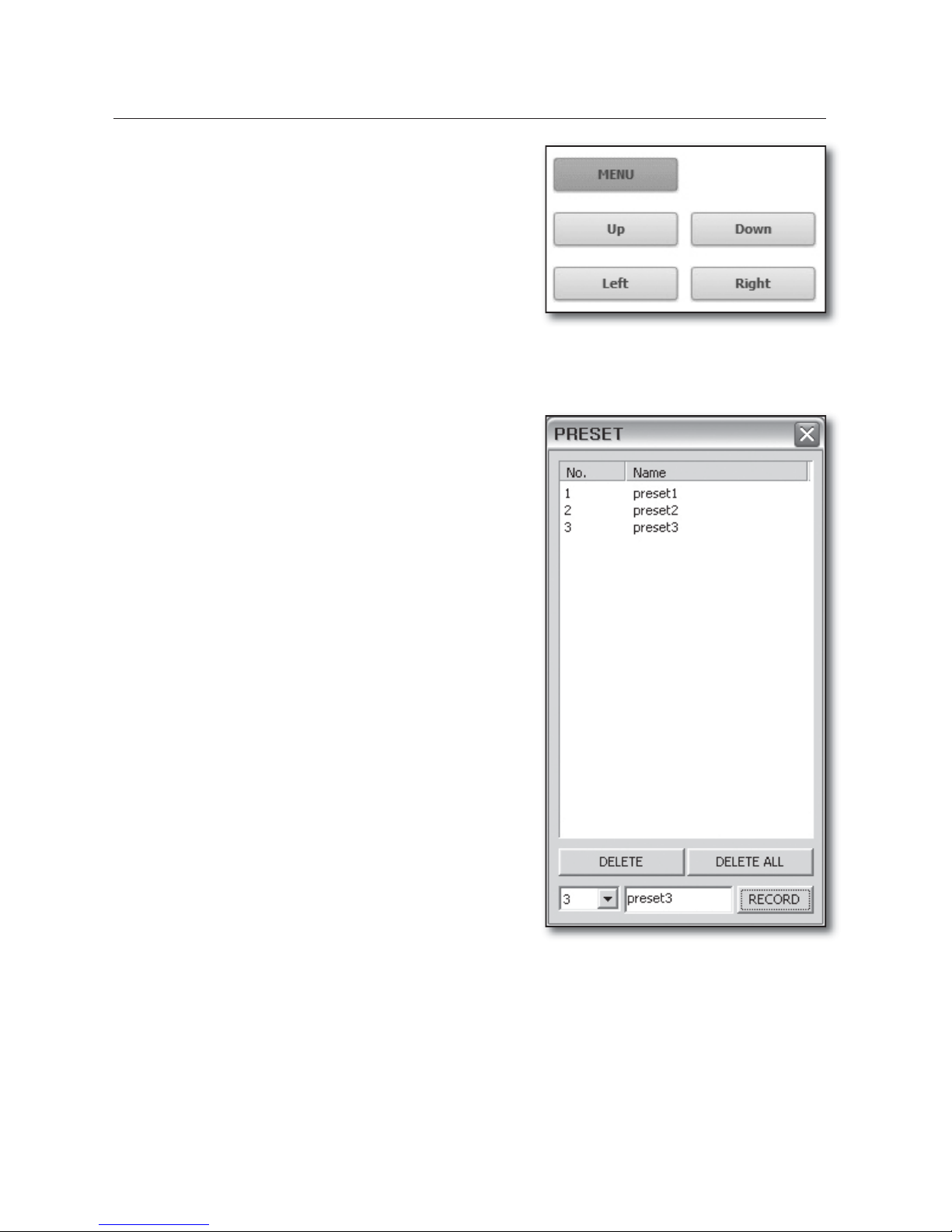
80_ web viewer
XFCWJFXFS
MENU : Appears the camera menu screen.
PRESET : Moves the lens direction to a preset direction.
If you click a preset, the camera moves to the selected
preset's position.
You can delete the selected preset or all presets.
You can save a new preset number and name.
You can save presets up to 20.
AUTOPAN : Moves the camera lens direction between
2 points set for the camera.
SCAN
: Moves the camera lens direction between 2 preset
points of the camera.
PATTERN
: You can set camera various movement patterns
such as zoom, move, etc. so that a camera automatically
moves according to the pattern.
While the DVR controls a PTZ camera, Web Viewer cannot
control the camera.
Camera menu setup is only available for camera supporting
the function.
Each function of PTZ is same to that of the DVR.
Pan/Tilt of the Smart dome camera is manipulated
automatically to center the camera to the mouse clicked
point.
If you drag the mouse using the left button on a certain point,
Pan/Tilt of the Smart dome camera is manipulated
automatically to center the camera to the middle point between the dragging start and end position.
Upward dragging will zoom out, while downward dragging will zoom in.
Tilt of Power PTZ operates properly within 45°.
Power and Pan Tilt functions are only available for camera supporting the functions.
Ex : Samsung SCC-C6475
•
•
1.
2.
3.
M
•
•
•
M
Page 81
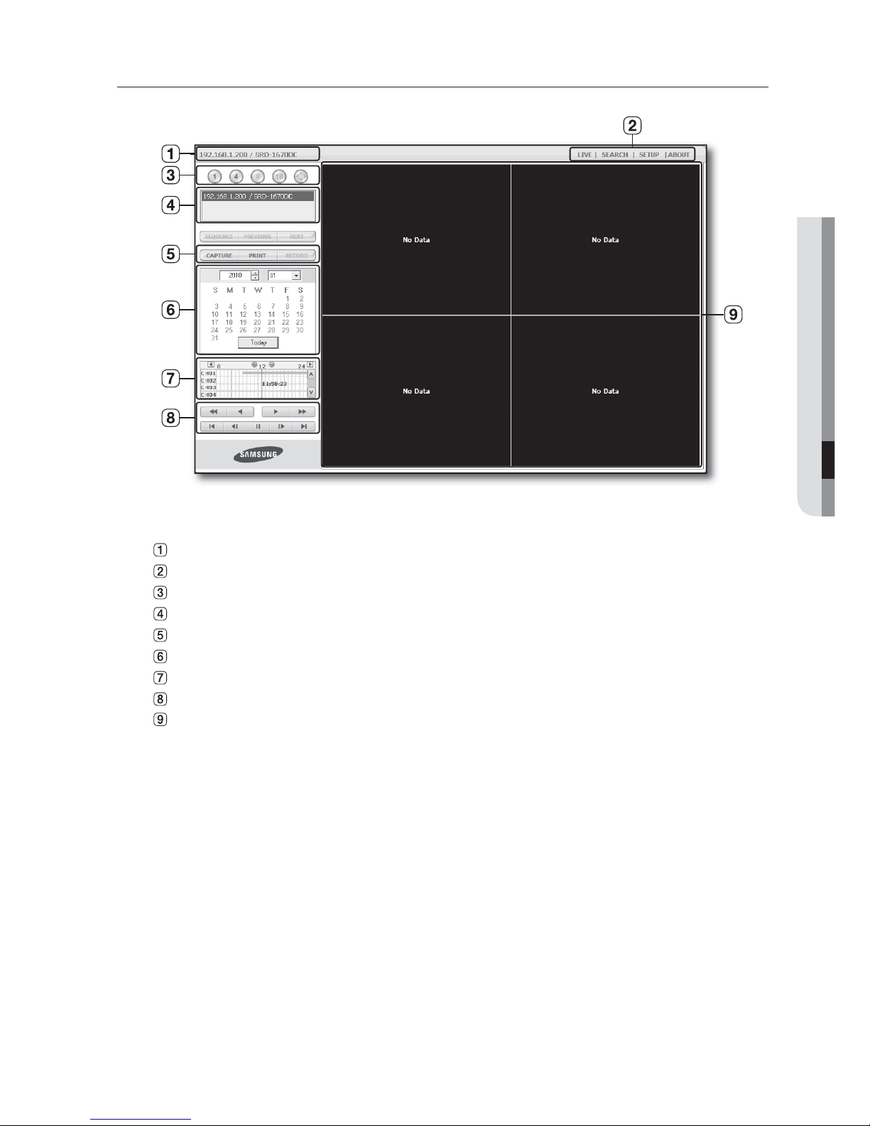
English _81
WEB VIEWER
USING SEARCH VIEWER
The Search Viewer screen consists of following :
This displays the IP address and the model name of the connected DVR.
These menus consist of <LIVE>, <SEARCH>, <SETUP>, <ABOUT>.
These buttons are used for the screen split and full screen mode.
Shows the IP address and model name of the connected DVR.
These buttons are used for capture, print, and save the image.
This displays a calendar at which you can search the recorded video.
This displays a timeline at which you can search the recorded video by the time.
These buttons are used for controlling playback.
This displays the screen for playback of recorded video.
<SEQUENCE>, <PREVIOUS>, <NEXT> buttons are not available in SEARCH menu.
M
Page 82
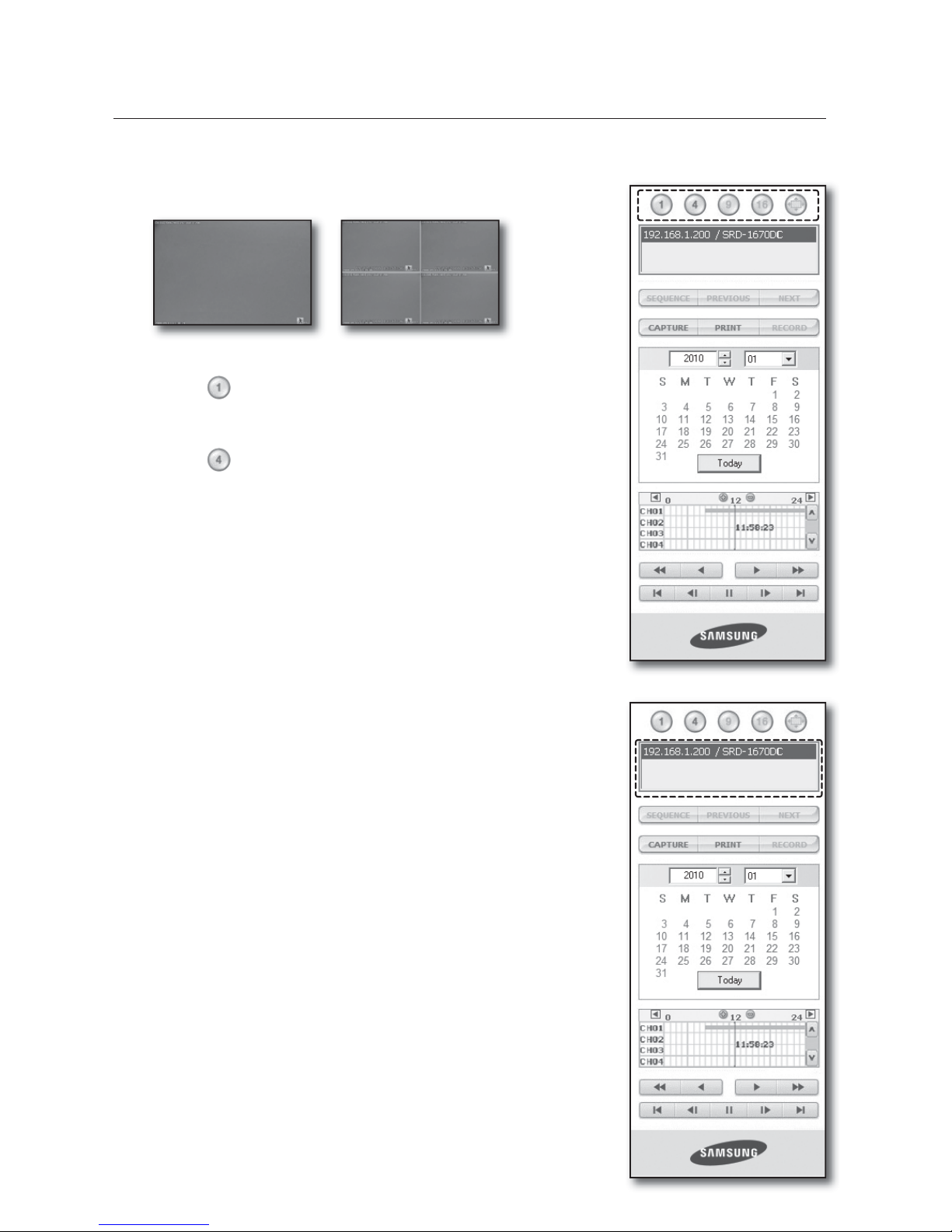
82_ web viewer
XFCWJFXFS
SPLIT-SCREEN
You can change the split mode by clicking each number icon.
Click <
> button.
The screen displays the selected camera connected to the DVR in
“SINGLE MODE”.
Click <
> button.
The screen displays the selected camera connected to the DVR in
“QUAD MODE”.
Only SINGLE and QUAD MODE are available in SEARCH menu.
If 16 channel DVR is connected, you can select a mode from SINGLE to
SIXTEEN MODE.
CONNECTED DVR
This displays the IP address and the status of the connecting DVR.
Connection failure message
No Response : Appears when the DVR does not respond.
Access Denied : Appears when the maximum number of users is exceeded.
The number of simultaneous connection is limited to 3.
•
•
M
M
SINGLE MODE QUAD MODE
Page 83
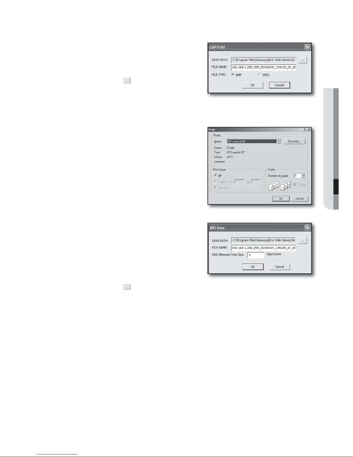
English _83
WEB VIEWER
SAVING THE LIVE SCREEN ON THE PC
CAPTURE : Saves the current screen into a BMP or JPEG
file.
The default saving path is “C:\Program Files\Samsung\Dvr
Web Viewer\SnapShot\Search”. To change the saving path,
click <SAVE PATH ( )> button and then select the path
you want. For Windows Vista or 7, the saving path is “C:\
users\(user ID)\AppData\LocalLow\Samsung\DVR Web
Viewer\Snapshot\”and it cannot be modified.
The file is automatically named as following : “IP address_Port number_YYYYMMDD_camera number_index”
Ex) 192.168.1.200_554_20100101_134132_01_00
PRINT : Prints the playback screen that is now being
displayed. It also prints IP address, time, camera number,
and current event state.
RECORD
: If you select a channel and click this button
during playback (only play), the video data is saved in a DVR
file. (It is saved in the designated folder on your PC.)
To stop recording, click this button again.
To record it, it is required at least 1GB of available space.
The default saving path is “C:\Program Files\Samsung\Dvr
Web Viewer\VideoClip\Search”. To change the saving path,
click <SAVE PATH (
)> button and then select the path you want. For Windows Vista or 7, the saving path is
“C:\users\(user ID)\AppData\LocalLow\Samsung\DVR Web Viewer\VideoClip\” and it cannot be modified.
The file is automatically named as following : “IP address_Port number_YYYYMMDD_camera number_index”
Ex) 192.168.1.200_554_20100101_135105_01_00
For AVI save, you need the Xvid codec for playing saved files.
•
M
•
•
M
Page 84
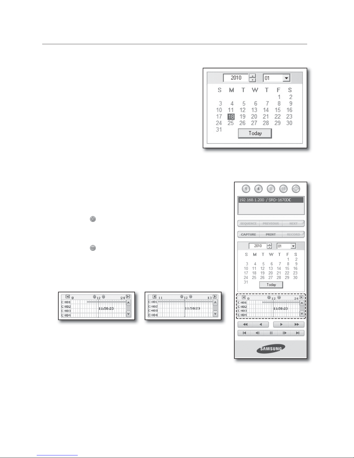
84_ web viewer
XFCWJFXFS
SEARCHING THE RECORDED VIDEO IN THE CALENDAR
If the video data has been recorded on a date, the date is
distinguished in green. If you click the date, the recorded video
information is displayed in the time line. When you click
<Today>, it is changed to today’s date.
SEARCHING THE RECORDED VIDEO IN THE TIMELINE
It displays the recorded video data status on the DVR after a date is
selected. The normal mode displays the time ranging from 0 to 24 Hours
while the extension mode displays the time every 2 hours.
[Normal Mode]
If you click <
> button, it changes to the extension mode.
Each time line represents 1 hour.
[Extension Mode]
If you click <
> button, it changes to the normal mode.
Each time line represents 5 minutes.
The channels are ranging from CH01 to CH16.
•
•
•
•
M
Page 85
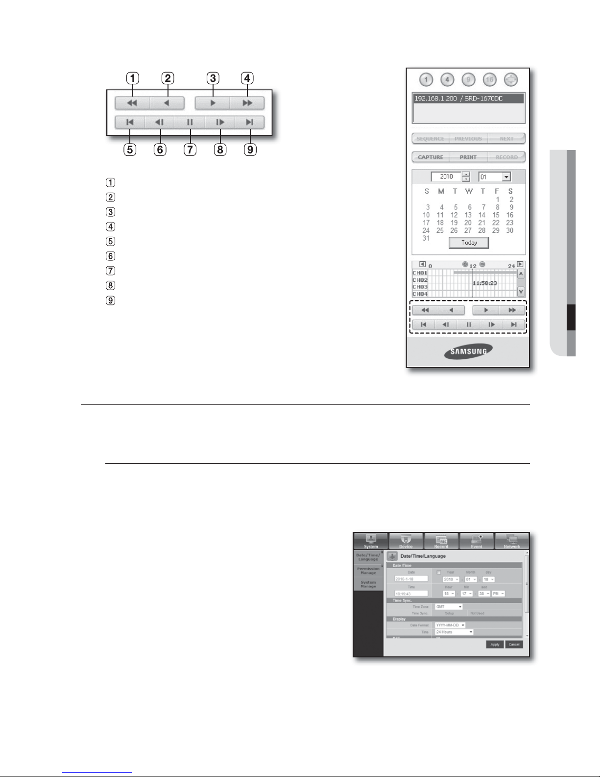
English _85
WEB VIEWER
CONTROLLING PLAYBACK
Fast Backward : Reverse-plays faster(2x).
Reverse Play : Performs Reverse Play.
Play : Performs playback.
Fast Forward : Plays faster(2x).
Go to First :
Moves the beginning time of recorded video in the time line.
Step Backward : Performs one step reverseplay by one frame.
Stop : Stops playing.
Step Forward : Performs one step forward by one frame.
Go to Last : Moves the last time of recorded video in the time line.
VIEWER SETUP
You can configure the DVR settings remotely on the network.
To configure the DVR settings, click <Setup>.
System
You can configure the various settings of the DVR system.
Date/Time/Language
For more information, refer to <Date/Time/Language> in the <System Setup> menu. (Page 34)
Select <Date/Time/Language> in the System menu.
Configure the DVR settings according to your system
environment.
Date/Time
Set the date and time.
1.
2.
•
Page 86
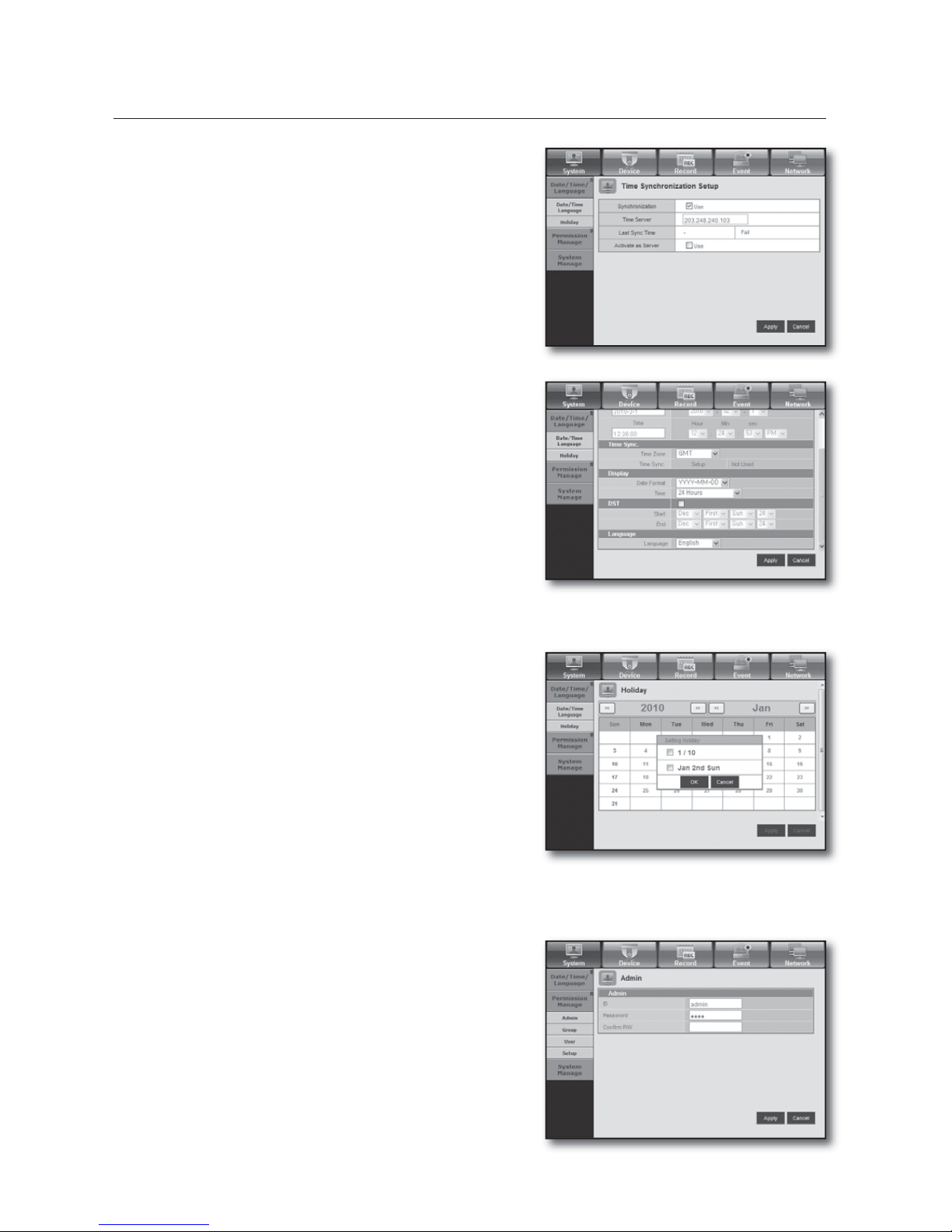
86_ web viewer
XFCWJFXFS
Time Synchronization Setup
Set the time synchronization.
Display
Date Format : Set the date type.
Time : Select a time format to display on the screen.
DST (Daylight Saving Time)
DST is displayed an hour ahead of the standard time of the
time zone.
Language
Select a preferred language for the DVR.
Holiday
You can set specific dates to Holidays according to your
preferences.
For more information, refer to <Setting Holiday> in the
<System Setup> menu. (Page 35)
Permission Management
For more information, refer to <Permission Management> in the <System Setup> menu. (Page 36)
Admin
You can change the admin ID or the password.
•
•
•
•
•
Page 87
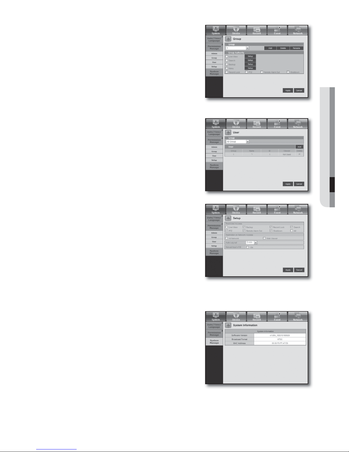
English _87
WEB VIEWER
Group
Users are classified into groups and the permission can be
set according to the group.
First of all, add a group.
User
You can add, change or remove a user or users.
Setup
You can set the user permission.
System Management
For more information, refer to <System Management> in the <System Setup> menu. (Page 40)
System Information
You can see information of the current system.
Check the software version, broadcast format and
MAC address.
•
•
•
•
Page 88
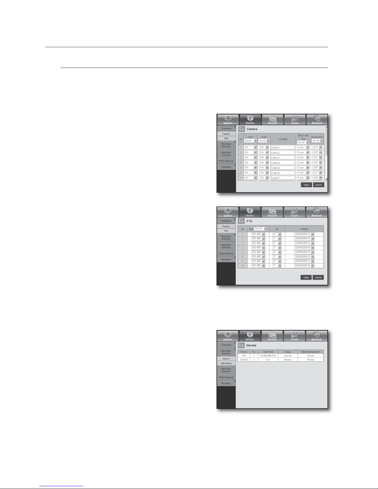
88_ web viewer
XFCWJFXFS
Device
You can check a list of devices that are connected to the DVR and configure the necessary settings.
Click <Device> in the menu screen.
For more information, refer to “Setting the Device”. (Page
44)
Camera
Camera
You can configure the settings of the camera that is
connected to the DVR.
SRD-830DC/1610DC/1630DC supports 1~4 channels of
sound inputs.
PTZ
You can configure the settings of the PTZ camera that is
connected to the DVR.
Set the Port, ID and protocol.
Storage Device
You can check and change the settings of the storage device.
Device
You will see a list of storage devices that are connected to the
DVR.
You can check the type, used/total, usage and status of the
device.
•
M
•
•
Page 89
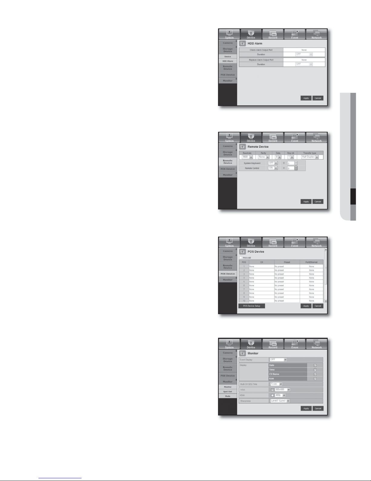
English _89
WEB VIEWER
HDD Alarm
You can set the alarm output channel and the alarm duration
for an error.
Remote Device
You can see a list of remote devices including PTZ cameras
and system keyboards that are connected to the RS-485 port
of the DVR and configure the necessary settings.
POS Device
You can set the channel, preset and communication port of
the POS device that is connected to the DVR.
You cannot set to use the POS device remotely.
Monitor
Monitor
You can configure the monitoring screen settings and set the
output system.
SRD-830DC/1610DC/1630DC does not support the HDMI
signal.
•
M
•
M
Page 90
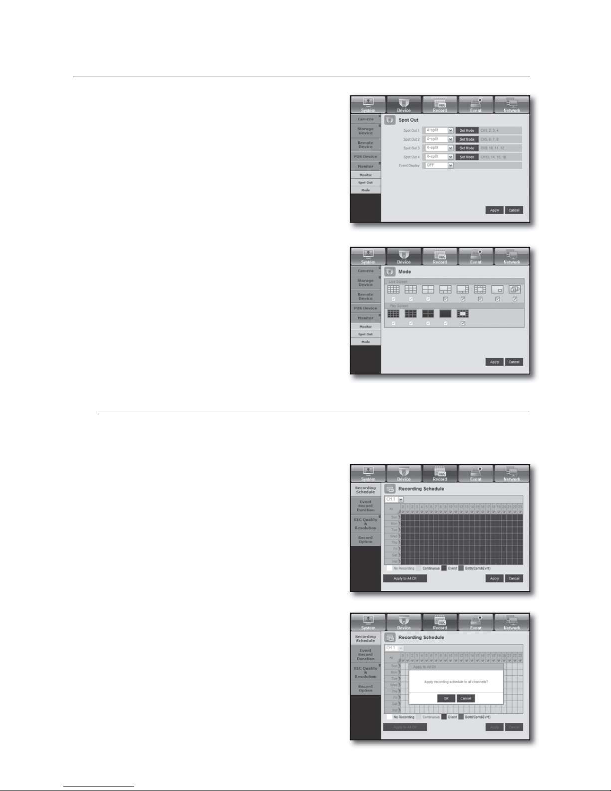
90_ web viewer
XFCWJFXFS
Spot Out
The registered user can view the event screen for the duration
set in <Event Display> if an event occurs from the appropriate
channel.
The number of Spot Out terminals differs according to the
model.
Mode
You can switch between live mode and play mode.
Record
For more information, refer to <Setting the Recording>. (Page 52)
Recording Schedule
If you set a recording schedule for a specific date and time,
the recording will start at that specific time.
- Apply to All CH : Click <Apply to All CH> to display the
confirmation window.
•
M
•
Page 91
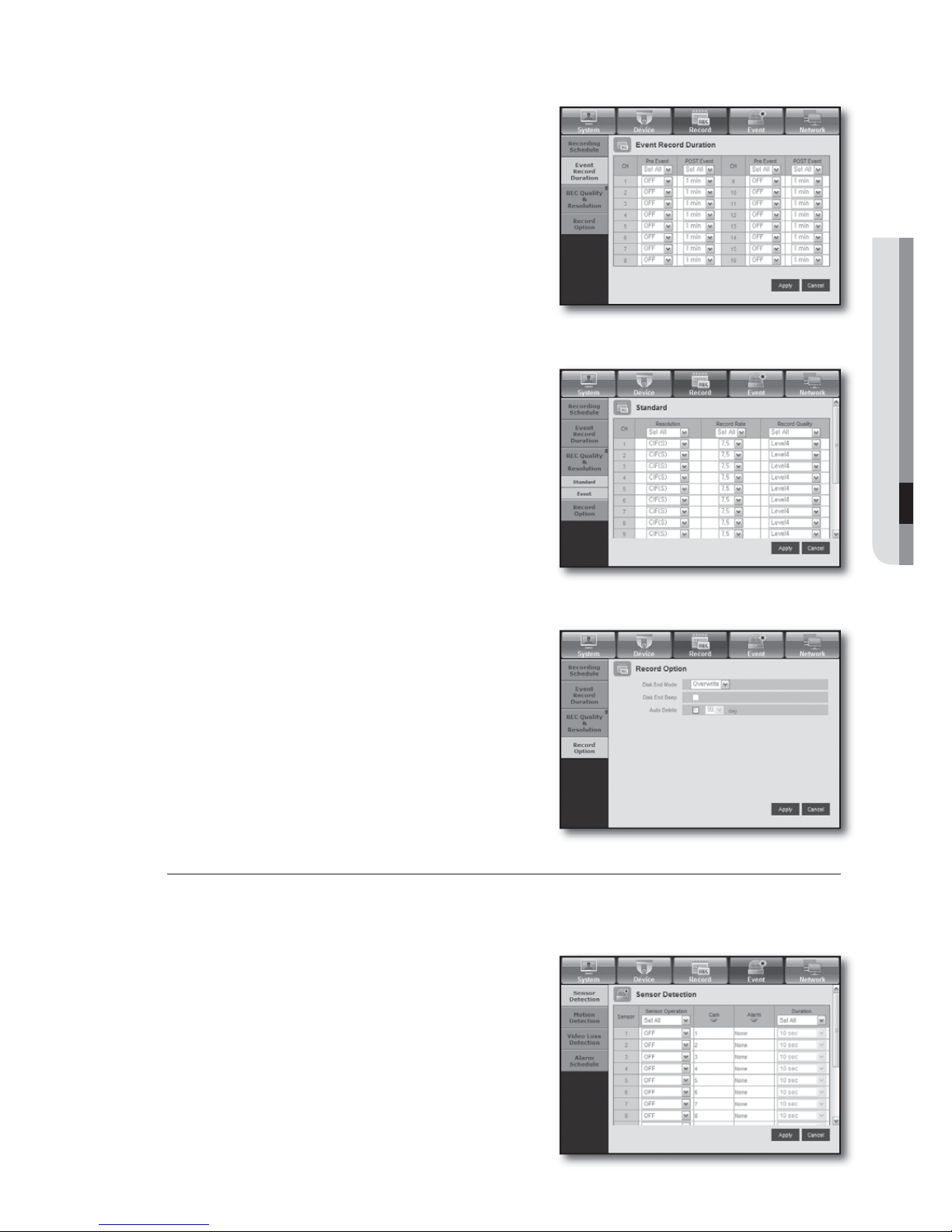
English _91
WEB VIEWER
Event Record Duration
You can set the start and end times of recording that will be
activated if an event occurs.
REC Quality & Resolution
Standard/Event
You can set the resolution, frame rate and recording quality for
each channel.
Record Option
You can set the Disk End Mode.
Event
For more information, refer to <Setting the Event>. (Page 55)
Sensor Detection
You can set the sensor operation mode and the synchronized
camera as well as the alarm output type and the duration.
•
Page 92
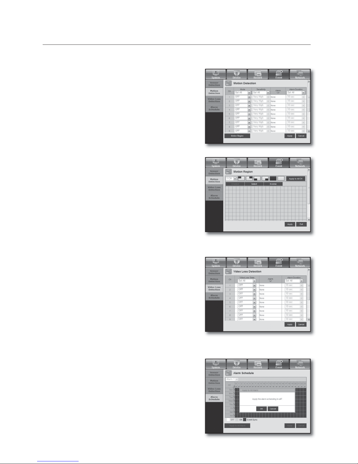
92_ web viewer
XFCWJFXFS
Motion Detection
You can set the motion detection mode and the sensitivity
as well as the alarm output type and the duration.
Motion Region
Set the target motion detection area
Video Loss Detection
You can set the alarm output time if a video loss occurs.
Alarm Schedule
You can schedule the alarm output according to the day of
the week and the time.
The default setting is Event Sync, which activates the alarm
only if an event occurs.
•
Page 93
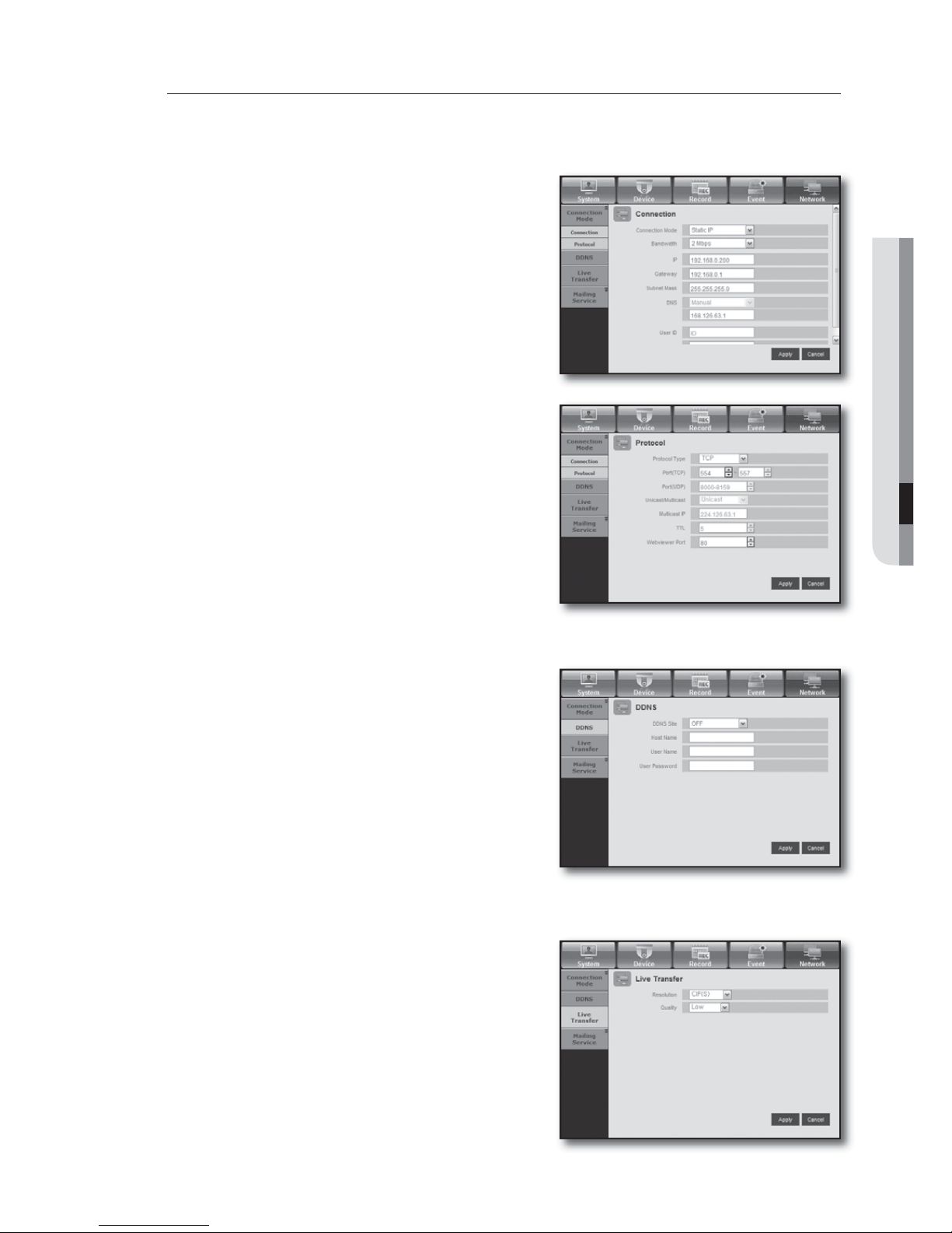
English _93
WEB VIEWER
Network
For more information, refer to <Network Configuration>. (Page 59)
Connection
A remote user can access the DVR via the network to check
the current mode and the IP address.
Connection
You can set the network connection route.
Protocol
You can configure the protocol related settings.
DDNS
You can check the DDNS settings.
Live Transfer
A remote user can set the images of the DVR.
Live Transfer
A remote user can set the image resolution of the transferred
data.
•
•
•
Page 94
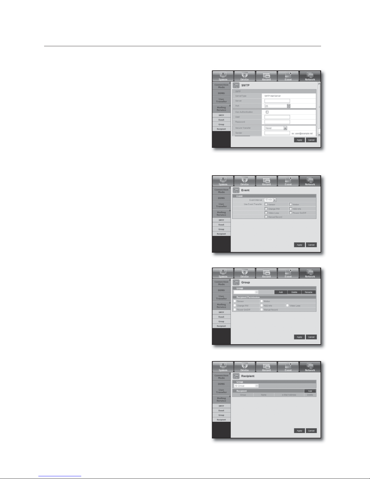
94_ web viewer
XFCWJFXFS
Mailing Service
You can specify the SMTP server that sends a mail if an event
occurs and set the recipient group and users.
SMTP
You can set the server that sends mails and specify if you use
the authentication process.
Event
You can set the event interval and specify which events the
server sends mails for.
Group
You can add a group to receive the mail if an event occurs
and set the permission to receive the event mail for each
group.
Recipient
You can add a user or users who will receive the mail.
•
•
•
•
Page 95
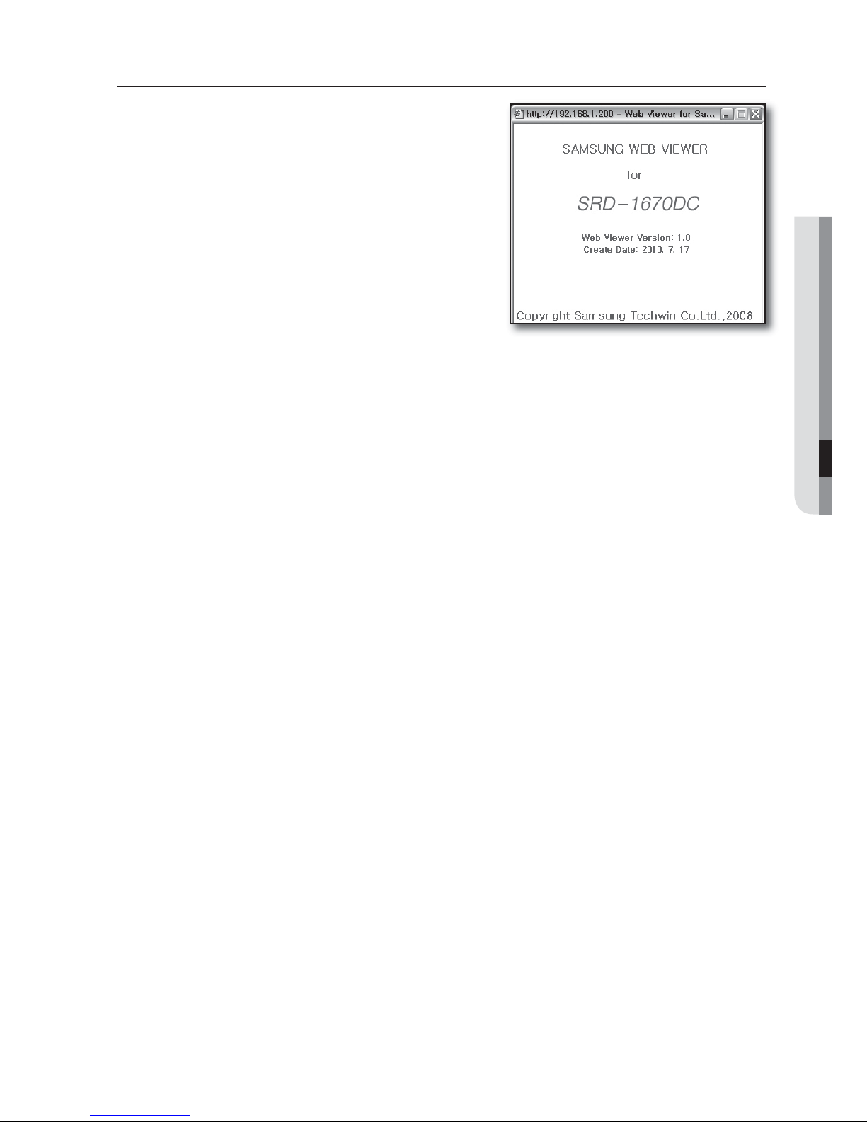
English _95
WEB VIEWER
ABOUT
Click <ABOUT>.
Displays the model name of connected DVR and the version
of Web Viewer.
Page 96
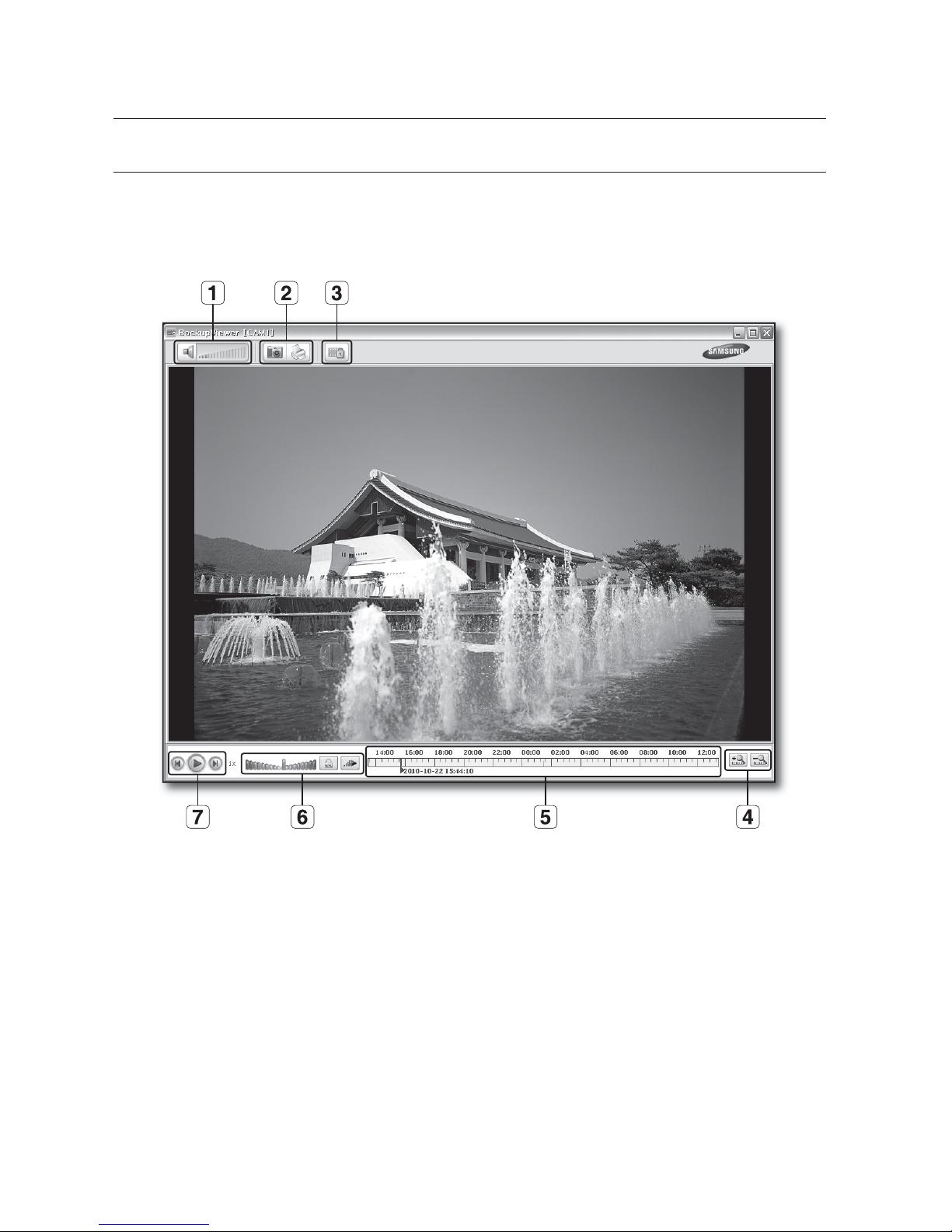
96_ backup viewer
SEC BACKUP VIEWER
You can play a file that is backed up in the format of SEC.
Backup in the format of SEC will involve in generating two files: one for the backup data and one for the viewer.
If you run the backup file viewer, the backup data file will be automatically played.
Recommended System Requirements
PCs with a lower specification than the recommended below may not fully support forward/backward and
high-speed playback.
OS : Windows XP professional, Windows Vista, Windows 7
CPU : Intel Core2-Duo 2.4GHz or higher
RAM : DDR PC-3200 1G or more
VGA : Geforce 6200 or higher
•
•
•
•
CBDLVQWJFXFS
Page 97
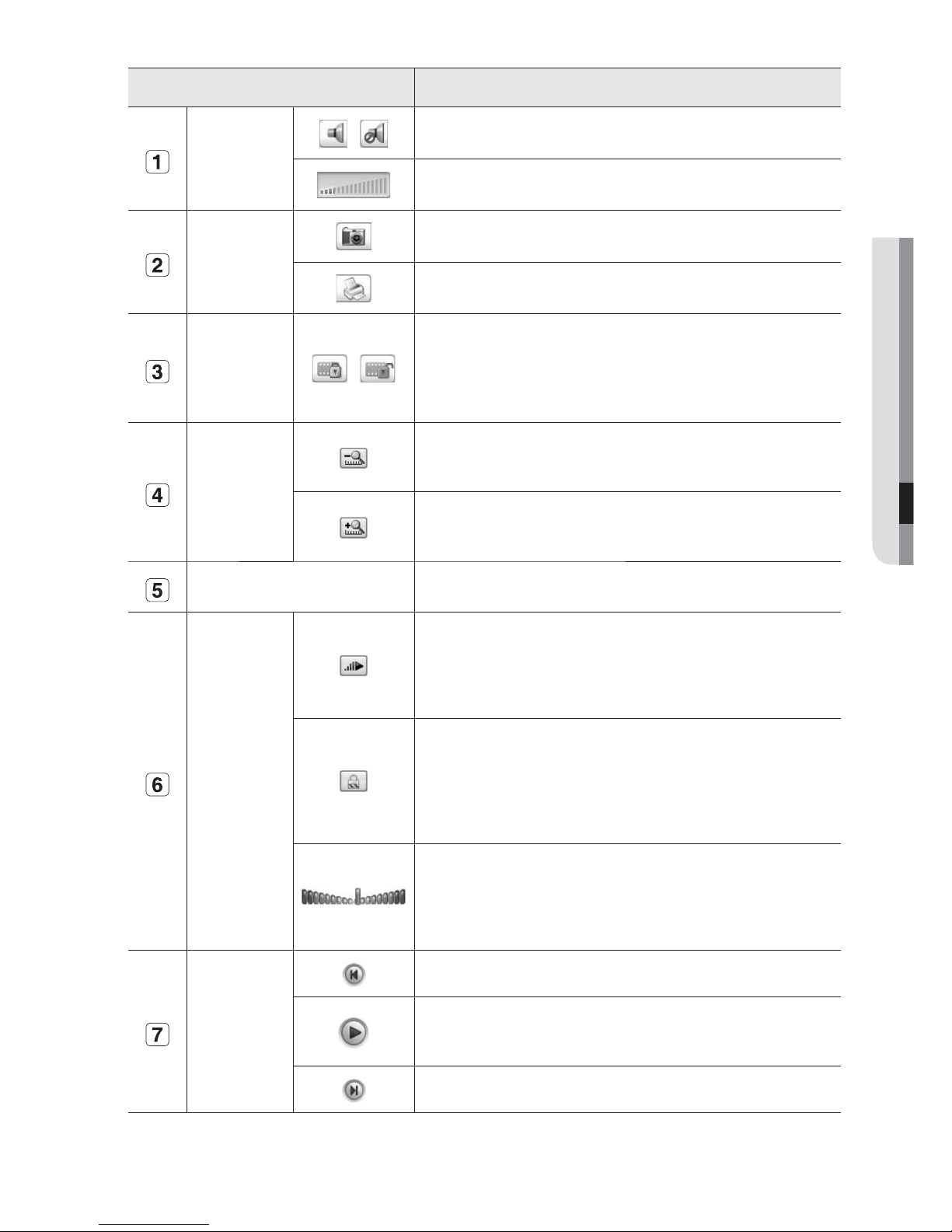
English _97
BACKUP VIEWER
Name Description
Audio
/
A toggle button. Each time you press this button, the audio output will toggle
between activated and deactivated.
You can adjust the volume level from 0 to 100.
Screen Printout
Saves the current screen as an image file. Supported file formats include
BMP and JPEG.
Prints out the current screen. You should have installed the appropriate printer
driver before you can print out the screen.
File Tamper
Detection
/
A toggle button. Each time you press this button, it will toggle between
activated and deactivated. The closed lock icon indicates activation of the file
tamper detection, which will blink the screen three times and stop playing if
an unauthorized manipulation of a data file is detected.
A message of "The file is forged” will display in the menu bar.
Zoom In/Out
Collapses the time range that is displayed on the range bar of the storage
time. You can collapse the range bar until the overall range is shortened to 24
hours.
Enlarges the time range that is displayed on the range bar of the storage
time. You can enlarge the range bar until the overall range is extended to 1
minute.
Display of storage time range
Displays the time range of a stored video file.
You can move the gridline of the range bar to select a time point to play.
Speed
A toggle button; each time you press this button, the "Slow Playback " icon
changes its color to display it’s activated/deactivated. If it is activated, you can
use the play speed control to adjust the play speed up to x1/32 forward and
backward respectively, whereas if deactivated, you can adjust up to x32
forward and backward.
A toggle button; each time you press this button, the "Lock Speed" icon
changes its color to display it’s activated/deactivated.
If activated, the adjusted speed will be kept even if you release the mouse on
the speed bar. If deactivated, the adjusted speed will be applied only while
you use the mouse to hold the adjusted speed, and if you release the mouse,
the speed will restore to x1.
You can adjust the play speed up to x32 forward and backward respectively,
which varies according to the frame rate per second of the source.
If the frame rate per second is between 20 and 30, the maximum speed is
limited to x4, if the FPS is between 11 and 19, it is limited to x16, and if the
FPS is 6 or less, it supports up to x32.
Play
Displays the next frame. This is available only if the playback is stopped.
A toggle button. Press it once to start playing the video and switch the button
mode to 'Pause', and press it again to switch the button mode to Play and
stop playing temporarily.
Displays the previous frame. This is available only if the playback is stopped.
Page 98
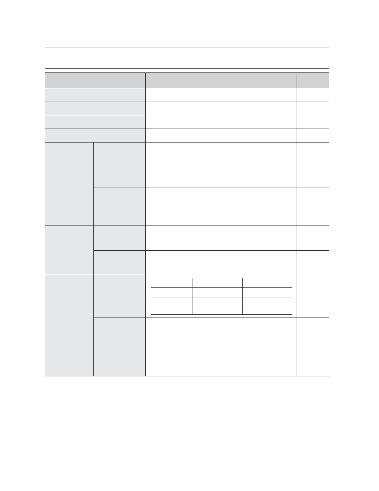
98_ appendix
PRODUCT SPECIFICATION (SRD-830DC/1610DC/1630DC)
Item Details Note
Operating System Embedded OS
Broadcast Format NTSC/PAL System
Input Voltage AC 100~240V
Power Consumption SRD-
830DC/1610DC/1630DC : 55W
Video
Video In
Composite 16(8) Channel
- 1.0Vp-p
- 75:Hi Z Termination
BNC Type
Loop Through Out 16(8) Channel
- Auto Termination
Video Out
Composite 2 Channel
- Normal Video Output 1 Channel
- Spot Output 1
- BNC Type
VGA 1 Channel
Audio
Audio In
Mono 4 Channel
4 Channel : RCA Type
- 5dBm, 600:
Audio Out
Mono 1 Channel
- 6dBm
RCA Type
Live Screen
Resolution & Frame
Rate
NTSC PAL
Resolution 704x480 704x576
Frame Rate
480ips(16Ch)/
240ips(8Ch)
400ips(16Ch)/
200ips(8Ch)
Display Mode
Single
Split Modes:
16CH : 4-, 6-, 8-, 9-, 13-, 16- splits
8CH : 4-, 6-, 8-, 9-, 13- splits
PIP
Mode sequence
Freeze
2 X Zoom
BQQFOEJY
Page 99
English _99
APPENDIX
Item Details Note
Record
Compression
Method
Video : H.264
Audio : G.723
Resolution & Quality
Resolution Spec. (Quality) Max Recording Rate
CIF(S)
352X240(NTSC)
/352X288(PAL)
Level8 (high)
~ Level1 (low)
240(120)ips(NTSC)/
200(100)ips(PAL)
2CIF(M)
704x240(NTSC)
/704x288(PAL)
Level8 (high)
~ Level1 (low)
120(60)ips(NTSC)/
100(50)ips(PAL)
4CIF(L)
704x480(NTSC)
/704x576(PAL)
Level8 (high)
~ Level1 (low)
60(30)ips(NTSC)/
50(25)ips(PAL)
SRD-1630DC
(SRD-1610DC
/830DC)
SRD-1630DC
(SRD-1610DC
/830DC)
SRD-1630DC
(SRD-1610DC
/830DC)
Record Mode
Normal Recording p REC button
Scheduled Recording p Schedule Table
Event Recording
- Alarm Detection
- Motion Detection
- Video Loss
- Pre & Post Recording
Frame Rate
NTSC : 0.9, 1.9, 3.8, 7.5, 15, 30ips
PAL : 0.8, 1.6, 3.1, 6.2, 12.5, 25ips
Storage Internal
SRD-830DC/1610DC/1630DC : SATA HDDx5(MAX)
MAX HDD size : 1TB x 5 = 5TB
If you want to
add an internal
HDD, please
refer to
“Adding a
HDD”.
(Page
15)
Play
Search Mode
Calendar Search
Event Search
- Alarm, Motion, Video Loss
Time/Date Search
Go to First
Go to Last
Backup Search
Text Search(for POS)
Motion Search
Preview
Resolution &
Specification
Resolution Specification
CIF(S)
352X240(NTSC)
/352X288(PAL)
240(120)ips(NTSC)/
200(100)ips(PAL)
2CIF(M)
704x240(NTSC)
/704x288(PAL)
120(60)ips(NTSC)/
100(50)ips(PAL)
4CIF(L)
704x480(NTSC)
/704x576(PAL)
60(30)ips(NTSC)/
50(25)ips(PAL)
SRD-1630DC
(SRD-1610DC
/830DC)
SRD-1630DC
(SRD-1610DC
/830DC)
SRD-1630DC
(SRD-1610DC
/830DC)
Page 100
100_ appendix
BQQFOEJY
Item Details Note
Play
Display Mode
Single /4-/9-/13-/16-splits
SRD-1610DC
SRD-1630DC
Single /4-/9-/13-splits
SRD-8300DC
Play Mode
Play, Pause, Stop, 2xDigital Zoom
Fast Forward/Fast Reverse
- 2x, 4x, 8x,16x, 32x, 64x
Backup
USB External HDD
USB CD/DVD Writer, Internal DVD
USB Memory
USB HDD-MAX 1(USB hub not supported)
Network Ethernet : 10/100/1000 BaseT, ADSL(PPPoE), DHCP
Serial Communication
RS-485
, Coaxial p PTZ Device Control
Remote Control Device
RS-232C p POS
Alarm
Input :
SRD-1610DC/1630DC : 16 channels
SRD-830DC : 8 channels
Remote Viewer
PC Requirements
CPU : Intel Core 2 Quad 2.5GHz or higher
RAM : 2G
VGA : 32M RAM(64M or more)
DirectX 8.1
Operating
Systems
Windows XP(Pro),
Windows-2000(Pro)
Windows Vista(Home Basic/Premium)
Windows 7
Features
Live Image Monitoring Mode
Local File Search & Play Back Mode
Remote File Search & Play Back Mode
Temperature (Operation) 0°C ~ 40°C (32°F ~ 104°F)
Temperature (Storage)
-20°C ~ 60°C (-4°F ~ 140°F)
Humidity (Operation) 20% to 85% RH
Humidity (Storage) 20% to 85% RH
Dimension (W x H x D) 440 x 88 x 430mm (17.32 x 3.46 x 16.92 inch)
H (leg not included)
Weight
SRD-830DC : ~7.42Kg(16.35lb)
SRD-1610DC/1630DC : ~7.55Kg(16.64lb)
It needs extra H/W to support ATM/POS function. So please contact your vendor to obtain H/W.
 Loading...