

Samsung 570DXn User Manual
A
SyncMaster 570DXn
Model
SyncMaster 570DXn
Select L anguage
Install Programs PDF Manuals Registration Safety Instructions
Introduction
Connections
Using the Software
djusting the LCD Display
Troubleshooting
Specifications
Information
Appen dix
© 2007 Samsung El ectronics Co., Ltd. All rights res erved.
Safety Instructions
Notational
Power
Installation
Clean
Others
Introduction
Connections
Using the Software
Adjusting the LCD Display
Troubleshooting
Specifications
Information
Appen dix
Select Language Main Page
Model
SyncMaster 570DXn
The color and appearance of the product may vary depending on the model, and the product specifications are
subject to change without prior notice for reasons of performance enhancement.
Safety Instructions
Notational
Please read the following safety instructions as they are designed to prevent damage to property and
harm to the user.
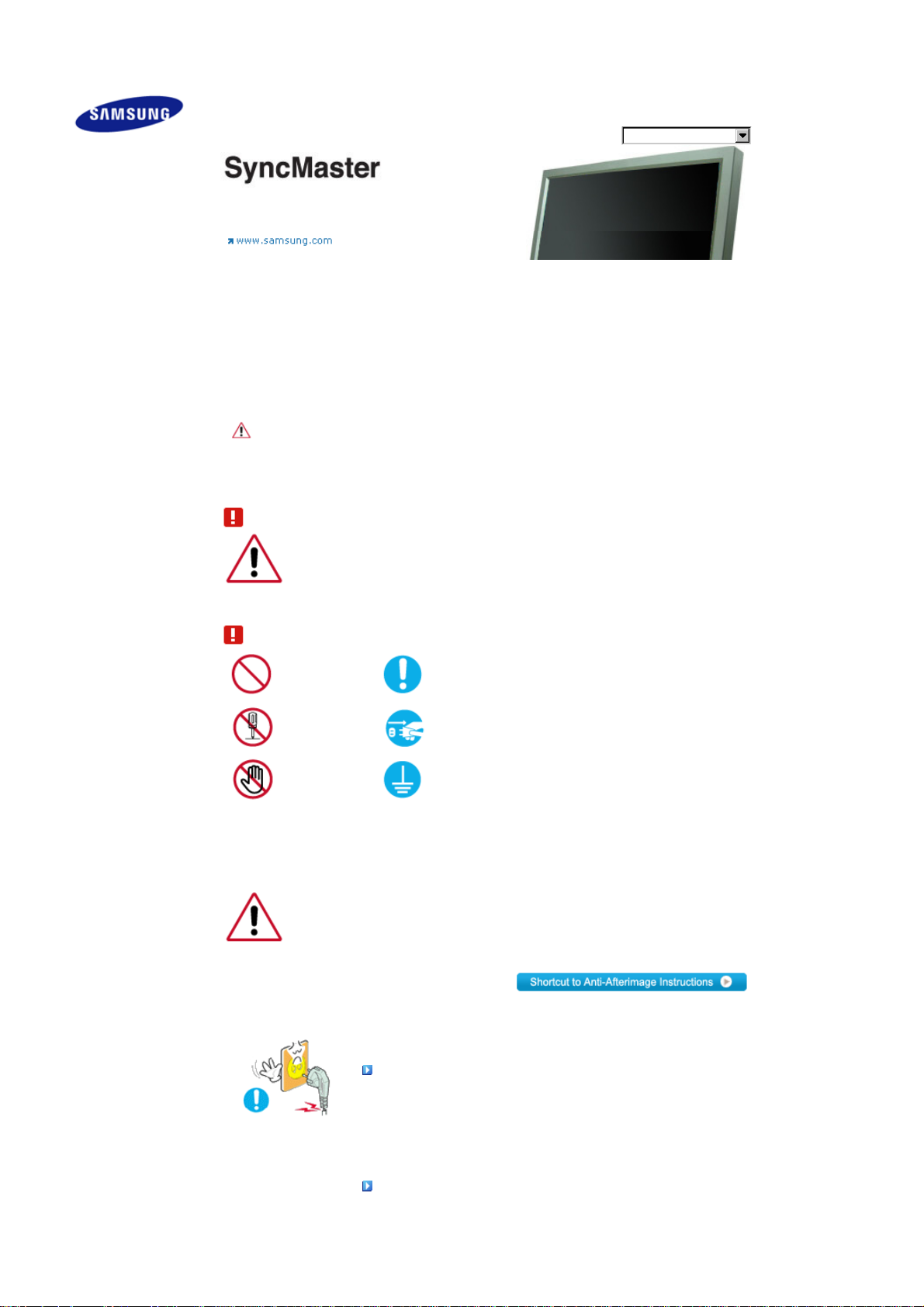
Warning / Caution
Failure to follow directions noted by this symbol could result in bodily harm or damage to the
equipm ent.
Notational Conventions
Prohibited Important to read and understand at all times
Do not disassemble Disconnect the plug from the outlet
Do not touch Ground to prevent an electric shock
When not used for an extended period of time, set your computer to DPM.
If using a screen saver, set it to active screen mode.
The images here are for reference only, and are not applicable in all cases (or countries).
Power
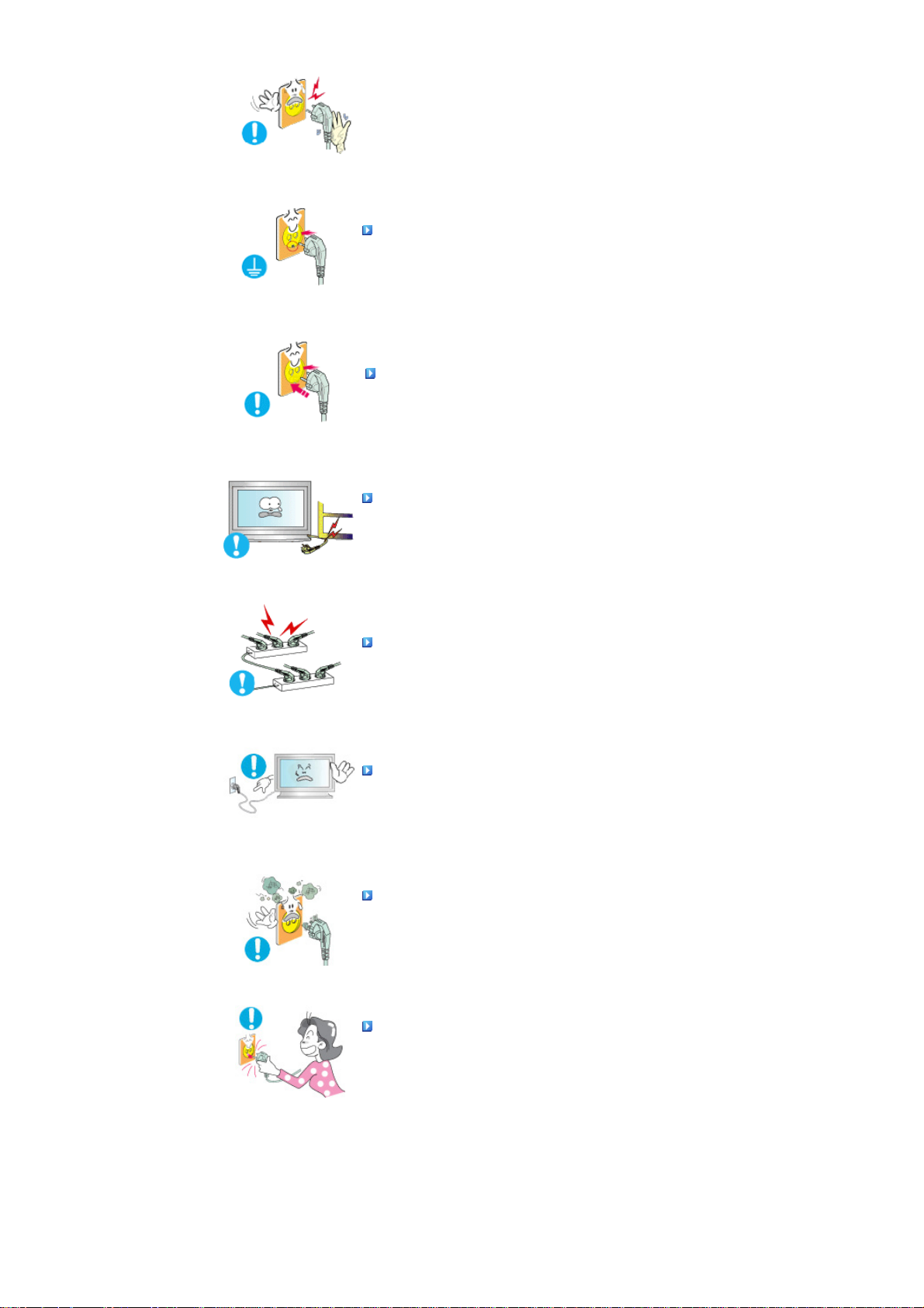
Do not use a damaged or loose plug.
z This may cause electric shock or fire.
Do not pull the plug out by the wire nor touch the plug with wet
hands.
z
This may cause electric shock or fire.
A
Use only a properly grounded plug and receptacle.
z
n improper ground may cause electric shock or equipment damage.(Class
l Equipment only.)
Insert the power plug firmly so that it does not come loose.
z
A bad connection may cause fire.
Do not excessively bend the plug and wire nor place heavy objects
upon them, whi ch could cause damage.
z
This may cause electric shock or fire.
Do not connect too many extension cords or plugs to one outlet.
z
This may cause fire.
Do not disconnect the power cord while using the LCD Display.
z A surge may be caused by the separation and may damage the LCD
Display.
Do not use the power cord when the connector or plug is dusty.
z If the connector or plug of the power cord is dusty, clean it with a dry cloth.
z
Using the power cord with a dusty plug or connector may cause electric
shock or fire.
To disconnect the apparatus from the mains, the plug must be
pulled out from the mains socket, therefore the mains plug shall be
readily op erable.
z
This may cause electric shock or fire.
Installation
Be sure to contact an authorized the Se rvice Cent er, when installing your LCD Display in a location
with heavy dust, high or low temperatures, high humidity, and exposed to chemical substances and
where it operates for 24 hours such as at airports, train stations etc.

Failure to do so may cause serious damage to your LCD Display.
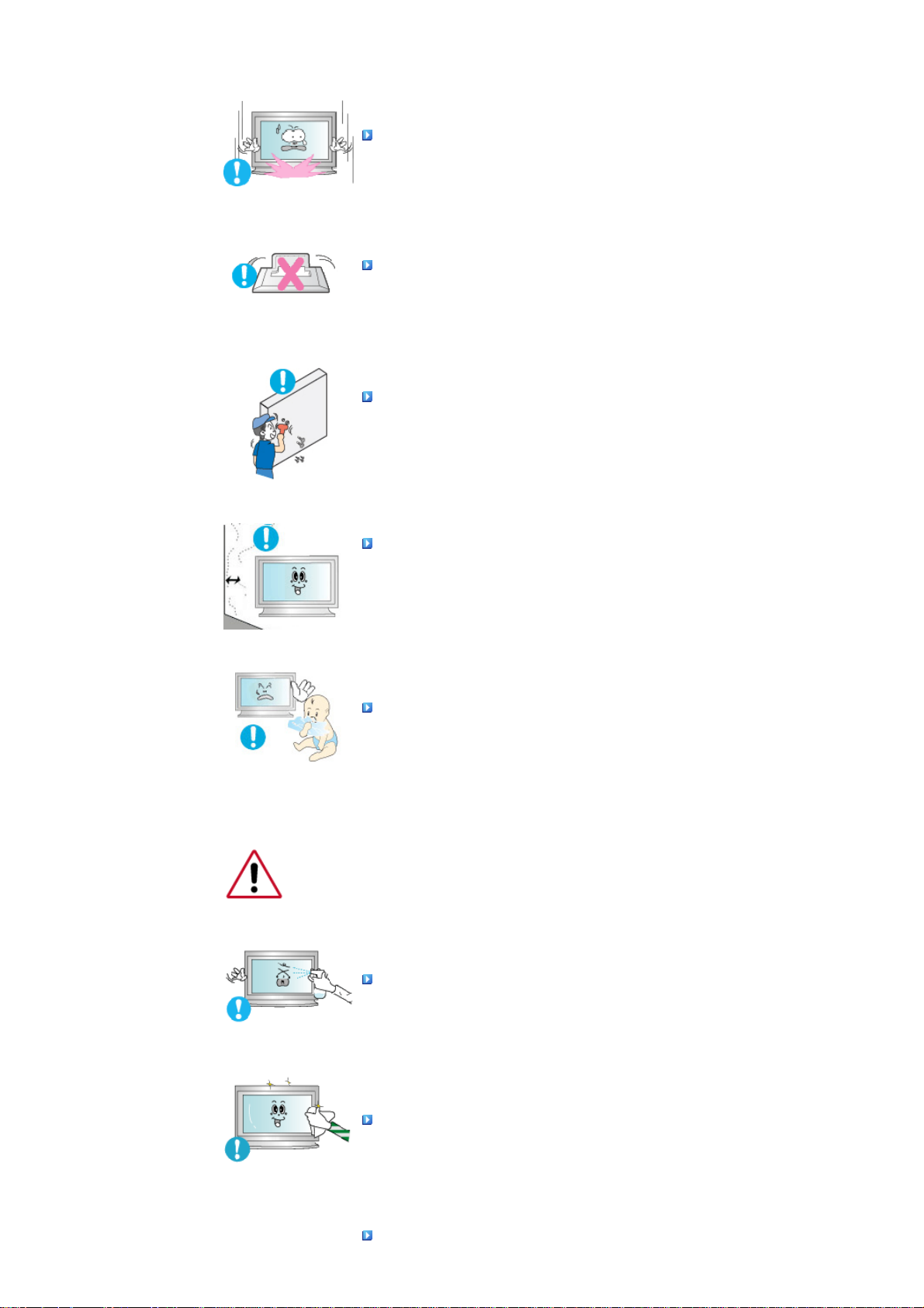
Place your LCD Display in a location with low humidity and a
minimum of dust.
z
Failure to do so may cause electric shock or fire inside the LCD Display.
Do not drop the LCD Display when moving it.
z
This may cause damage to the product or the person carrying it.
Install the LCD Display base in a showcase or shelf so that the end
of the base does not protrude from the showcase or shelf.
z
Dropping the product may cause damage to the product or the person
carrying it.
Do not place the product on an unstable or small surface area.
z
Place the product on an even and stable surface ,as the product may fall
and cause harm to someone walking by, specifically children.
Do not place the product on the floor.
z Take care, as someone, specifically children may trip over it.
TO PREVENT THE SPREAD OF FIRE, KEEP CANDLES OR OTHER
OPEN FLAMES AWAY FROM THIS PRODUCT AT ALL TIMES.
z Otherwise, this may cause fire.
Keep any heating devices away from the power cable.
z
A melted coating may cause electric shock or fire.
Do not install the product in places with poor ventilation, for
instance, a bookshelf, closet, etc.
z
Any increase in the internal temperature may cause fire.
Put down the LCD Display carefully.
z Failing to do so may damage the LCD Display.
Do not place the LCD Display face down.
z This may damage the TFT-LCD surface.
The installation of the bracket must be done by a qualified
professional.
z Installing the bracket by unqualified personnel may result in injury.
z
Always use the mounting device specified in the owner's manual.
When installing the product, make sure to keep it away from the wall
(more than 10 cm / 4 inches) for ventilation purposes.
z
Poor ventilation may cause an increase in the internal temperature of the
product, resulting in a shortened component life and degraded
performan ce.
Keep the plastic packaging (bag) out of children's reach.
z The plastic packaging (bag) may cause suffocation if children play with it.
Clean
When cleaning the LCD Display case or the surface of the TFT-LCD screen, wipe with a slightly
moistened, soft fabric.
Do not spray water or detergent directly onto the LCD Display.
z This may cause damage, electric shock or fire.
Use the recommended detergent with a smooth cloth.
If the connector between the plug and the pin is dusty or dirty, clean
it properly using a dry cloth.
z A dirty connector may cause electric shock or fire.
Make sure to unplug the power cord before cleaning the product.
z
Otherwise, this may cause electric shock or fire.
Unplug the power cord from the power outlet and wipe the product
using a soft, dry cloth.
z
Do not use any chemicals such as wax, benzene, alcohol, thinners,
insecticide, air freshener, lubricant or detergent.
Others
Do not remove the cover (or back).
z This may cause electric shock or fire.
z
Refer to a qualified servicing company.
If your LCD Display does not operate normally - in particular, if there
is any unusual sound or smell coming from the LCD Display -
unplug it immediately and contact an authorized dealer or the
Service Center.
z
This may cause electric shock or fire.
Keep the product away from places exposed to oil, smoke or
moisture; do not install inside a vehicle.
z This may cause a malfunction, electric shock or fire.
z
In particular, avoid operating the LCD Display near water or outdoors where
the LCD Display could be exposed to snow or rain.
If the LCD Display is dropped or the casing is damaged, turn the
LCD Display off and unplug the power cord. Then contact the
Service Center.
z The LCD Display may malfunction, causing electric shock or fire.
Disconnect the plug from the outlet during storms or lightning or if
it is not used for a long p eriod of time.
z Failure to do so may cause electric shock or fire.

Do not try to move the LCD Display by pulling only the wire or the
signal cable.
z This may cause a breakdown, electric shock or fire due to damage to the
cable.
Do not move the LCD Display right or left by pulling only the wire or
the signal cable.
z This may cause a breakdown, electric shock or fire due to damage to the
cable.
Do not cover the vents on the LCD Display cabinet.
z
Bad ventilation may cause a breakdown or fire.
Do not place water containers, chemical products or small metal
objects on the LCD Display.
z
This may cause a malfunction, electric shock or fire.
z If a foreign substance enters the LCD Display , unplug the power cord and
contact the Service Center.
Keep the product away from combustible chemical sprays or
inflammable substances.
z This may cause an explosion or fire.
Never insert anything metallic into the LCD Display openings.
z This may cause electric shock, fire or injury.
Do not insert metal objects such as chopsticks, wire and tools or
inflammable objects such as paper or matches into the vent,
headphone port or AV ports or etc.
z This may cause electric shock or fire. If an alien substances or water enters
the product, turn the product off, unplug the power connector from the wall
outlet and co ntact the Service Center.
When viewing a fixed screen for an extended period of time, residual
image or blurriness may appear.
z Change the mode to energy saving mode or set a screensaver to a
changing picture when away from the LCD Display for an extended period
of time.
Adjusts the resolution and frequency to the level appropriate for the
model .
z
An inappropriate resolution may cause undesirable picture quality.
57 inch (143 cm) - 1920 x 1080
Viewing the LCD Display continuously at a too close angle may
result in damage to your eyesight.
To ease eye strain, take at least a five-minute break after every hour
of using the LCD Display.
Do not install the product on an unstable, uneven surface or a
location prone to vibrations.
z Dropping the product may cause damage to the product or the person
carrying it. Using the product in a location prone to vibrations may shorten
the lifetime of the product or may cause the product to catch fire.
When moving the LCD Display , turn off and unplug the power cord.
Make sure that all cables, including the antenna cable and cables
connected to other devices, are disconnected before moving the
LCD Display.
z Failur e to dis connect cables may damage it and cause f ire or electric
shock.
Make sure there are more than two people when moving the
product.
z Dropping the product may cause a malfunction or injury to the person
carrying it.
Place the product out of children’s reach, as they could damage by
hanging on to it.
z
A falling product may cause injury to the person or even fatality.
When not using the product for an extended period of time, keep the
product un plugged.
z Otherwise, this may cause heat emission from the accumulated dirt or
degraded insulation, causing electric shock or fire.
Do not place your children's favorite toys or any other objects of
interest on the product.
z Children may try to climb on the product to retrieve an object. The product
could fall, causing injury or even fatality.
When removing batteries from the remote control, be careful that
they are not swallowed by children. keep the batteries out of
children's reach.
z
If the batteries are swallowed, see a doctor immediately.
When replacing batteries, place the batteries in the correct +/-
polarity position as indicated on the battery holder.
z
The incorrect polarity may cause a battery to break or leak and may cause
fire, injury, or contamination (damage).
Use only specified standard batteries. Do not use new and used
batteries together.
z
This may cause a battery to break or leak and may cause fire, injury, or
contam ination ( damage).
The batteries (and rechargeable batteries) is not ordinary refuse and
must be returned for recycling purposes. The customer is
responsible for returning the used or rechargeable batteries for
recycling purposes as the consumer.
z The customer can return used or rechargeable batteries to a nearby public

recycling center or to a store selling the same type of the battery or
rechargeable battery.
© 1995~2007 SAMSUNG. ALL Rights Reserved
Safety Instructions
Introduction
Package Contents
Your LCD Display
Machanical Layout
Connections
Using the Software
Adjusting the LCD Display
Troubleshooting
Specifications
Information
Appendix
Select Language Main Page
Model
SyncMaster 570DXn
The color and appearance of the product may vary depending on the model, and the product specifications are
subject to change without prior notice for reasons of performance enhancement.
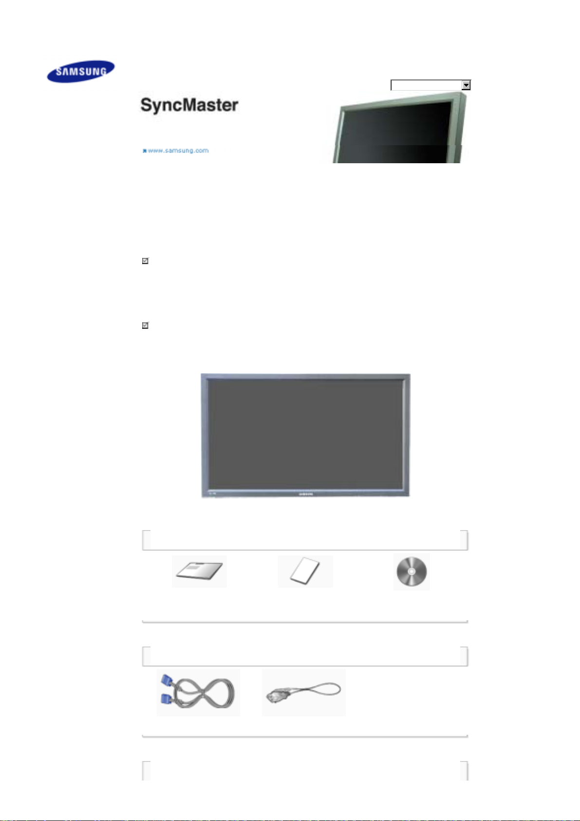
Introduction
Package Contents
Note
• Please make sure the following items are included with your LCD Display.
If any items are missing, contact your dealer.
Contact a local dealer to buy optional items.
Note
• This stand is not for the Floor Standing Type.
Manuals
Quick Setup Guide
(Not available in all locations)
LCD Display
Warranty Card
User's Guide, MDC Software,
MagicNet Software
Cables
D-Sub Cable Power Cord
Other
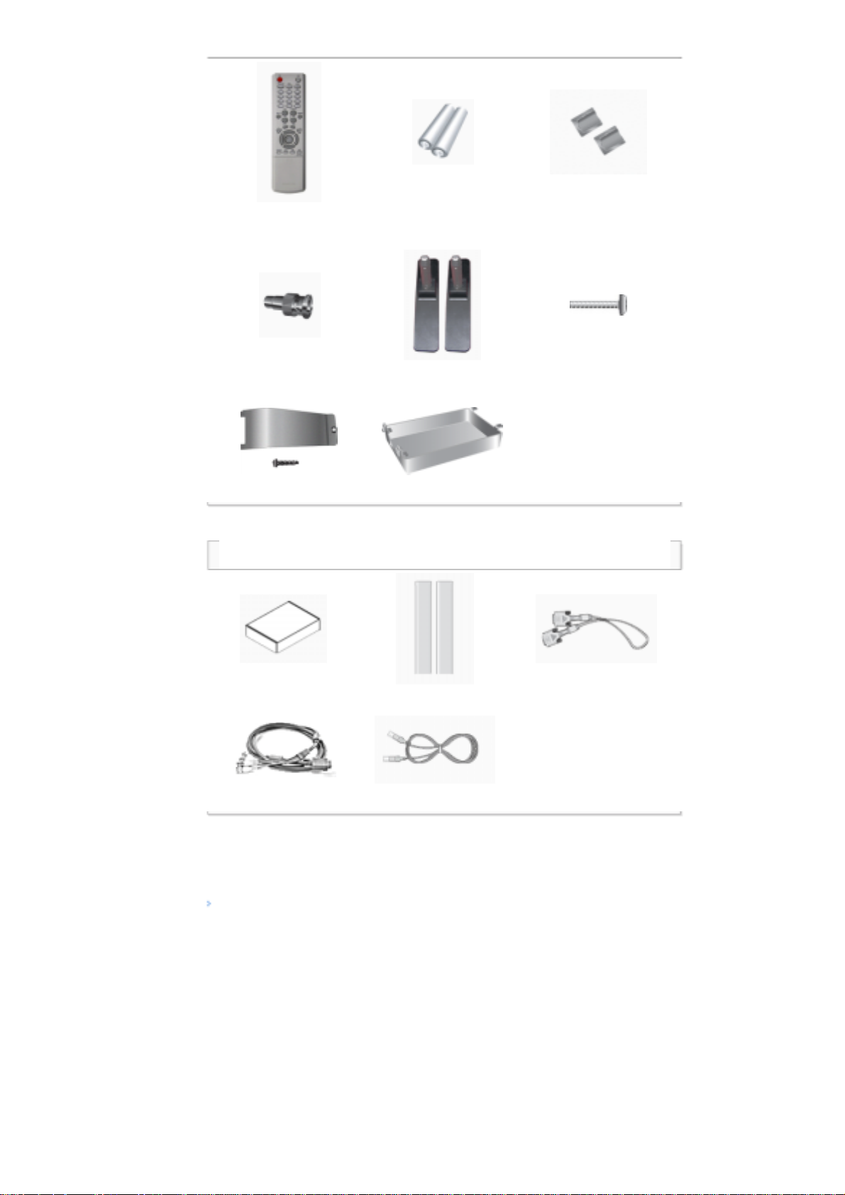
Remote Control
Batteries (AAA X 2)
(Not available in all locations)
Cover-Hole
BNC to RCA
Adaptor Jack
Semi Stand Screw: 4 EA
USB Holder & Screw (1EA) HDD Cover
Sold separately
Wall Mount KIT Speaker Set DVI Cable
BNC Cable LAN Cable
Your LCD Display
Front
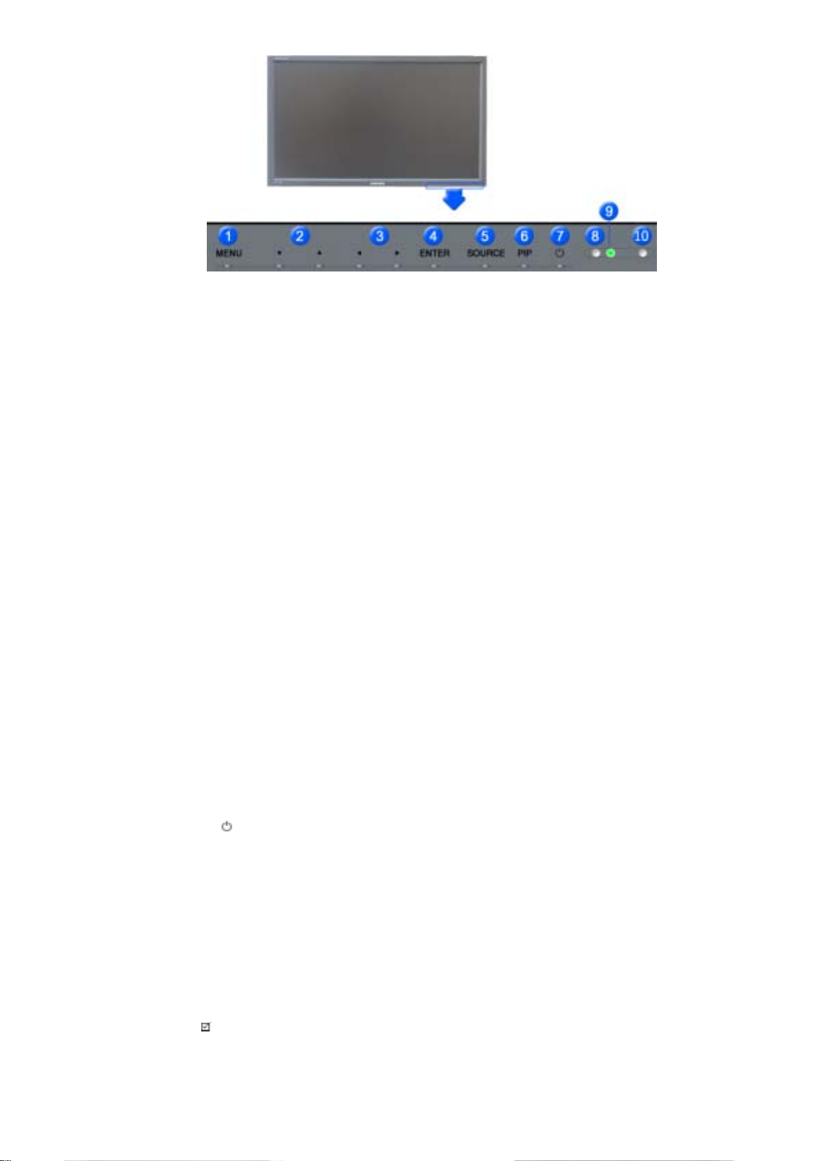
1) MENU
Opens the on-screen menu and exits from the menu or closes the adjustment menu.
2) Navigate buttons (Up-Down buttons)
Moves from one menu item to another vertically or adjusts selected menu values.
3) Adjust buttons (Left-Right buttons)/ Volume buttons
Moves from one menu item to another horizontally or adjusts selected menu values.
Adjusts the audio volume.
4) ENTER
Activates a highlighted menu item.
5) SOURCE
Switches from PC mode to Video mode.
Changing the source is only allowed for external devices that are connected to the LCD Display at the time.
[PC] → [BNC] → [DVI] → [AV] → [S-Video] → [Component] → [HDMI] → [MagicNet]
>> Click here to see an animation clip.
6) PIP
Push the PIP button to turn the PIP screen On / Off.
More than one PIP cannot overlap on screen as BNC and the component use the same terminal.
>> Click here to see an animation clip.
•
PC
AV / S-Video / Component / HDMI Mode
•
BNC
AV / S-Video / HDMI Mode
•
DVI
AV / S-Video / Component Mode
•
AV / S-Video
PC / BNC / DVI Mode
•
Component
PC / DVI Mode
•
HDMI
PC / BNC Mode
7)
Power button
Turns the LCD Display On/Off.
8) Brightness Sensor
The product's Brightness Sensor function automatically detects the surrounding brightness using a
brightness sensor and adjusts its brightness accordingly.
9) Power indicator
Shows PowerSaver mode by blinking green.
10) Remote Control Sensor
Aim the remote control towards this spot on the LCD Display.
Note
•See PowerSaver described in the manual for further information regarding power saving functions. For
energy conservation, turn your LCD Display OFF when it is not needed or when leaving it unattended for
long periods.

Rear
Note
• For detailed information concerning cable connections, refer to Connecting Cables under Setup. The LCD
Display 's configuration at the back may vary slightly depending on the LCD Display model.
1) POWER S/W ON [ | ] / OFF [O]
Switches the LCD Display On/Off.
2) POWER IN
The power cord plugs into the LCD Display and
the wall plug.
3) REMOTE OUT/IN
You can use a wired remote control by
connecting it to your monitor.
4) RS232C OUT/IN (RS232C Serial PORT)
MDC(Multiple Display Control) Program Port
5) DVI / PC / HDMI IN [PC/DVI/BNC AUDIO
IN] (PC/DVI/BNC/HDMI Audio Connection
Terminal (Input))
6) DVI / PC / HDMI IN [HDMI]
Connect the HDMI terminal at the back of your
monitor to the HDMI terminal of your digital
output device using a HDMI cable.
7) DVI / PC / HDMI IN [RGB] (PC Video
Connection Terminal)
Using a D-Sub Cable (15 pin D-Sub) - PC
mode (Analog PC)
8) DVI / PC / HDMI IN [DVI(HDCP)] (PC
Video Connection Terminal)
Using a DVI Cable (DVI-D to DVI-D) - DVI
mode (Digital PC)
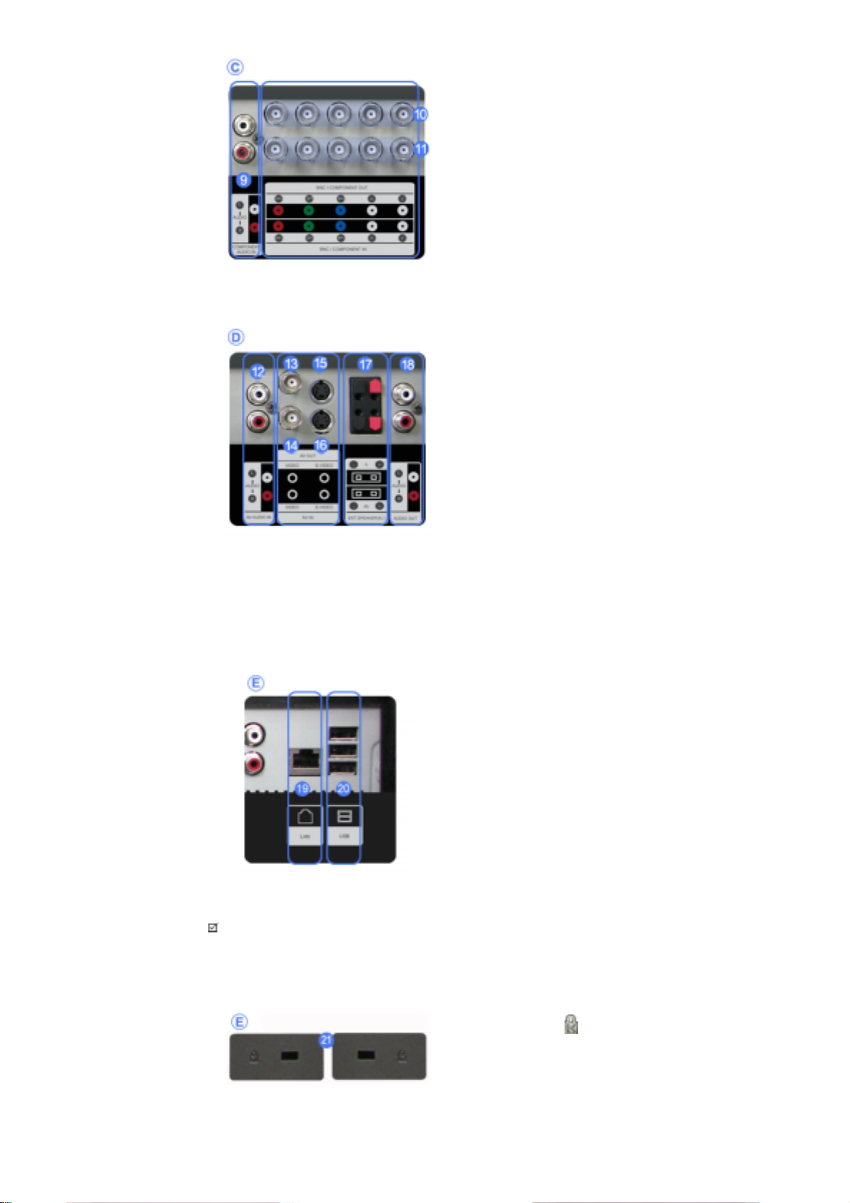
9) COMPONENT AUDIO IN [L-AUDIO-R]
(Component Audio Connection Terminal
(Input))
R
10) BNC/COMPONENT OUT [R/P
, G/Y, B/PB,
H, V] (BNC/Component Connection
Terminal (Output))
BNC (Analog PC) Connection: connecting the R,
G, B, H, V ports
Component Connection: connecting the P
ports
P
B
, Y,
R
11) BNC/COMPONENT IN [R/PR, G/Y, B/PB, H,
V] (BNC/Component Connection Terminal
(Input))
12) AV AUDIO IN [L-AUDIO-R] (LCD Display
Audio Connection Terminal (Input))
13) AV OUT [VIDEO] (VIDEO Connection
Terminal): AV mode (Output)
14) AV IN [VIDEO] (VIDEO Connection
Terminal) (Input)
15) AV OUT [S-VIDEO] (S-VIDEO Connection
Terminal): S-VIDEO mode (Output)
16) AV IN [S-VIDEO] (S-VIDEO Connection
Terminal) (Input)
17) EXT SPEAKER(8 Ω)[- - L - +, - - R - +] (EXT
Speaker Connection Terminal)
18) AUDIO OUT [L-AUDIO-R] (LCD Display
Audio Connection Terminal (Output))
AUDIO OUT is the terminal for sound output of
PC, DVI or BNC.
19) LAN (LAN Connection Terminal)
20) USB (USB Connection Terminal)
Keyboard / Mouse, Mass Storage Device
Compatible.
Note
• The number of LCD Displays that can be connected to loopout may differ depending on the cables, signal
source etc. With cables where there is no degradation or signal source, up to ten LCD Displays can be
connected.
21) Kensington Lock
The Kensington lock is a device used to
physically fix the system to something when
using it in a public place. (The locking device has
to be purchased separately.)
For using a locking device, contact the place
of purchase.
Note
W
•See Connecting the LCD Display for further information regarding cable connections.
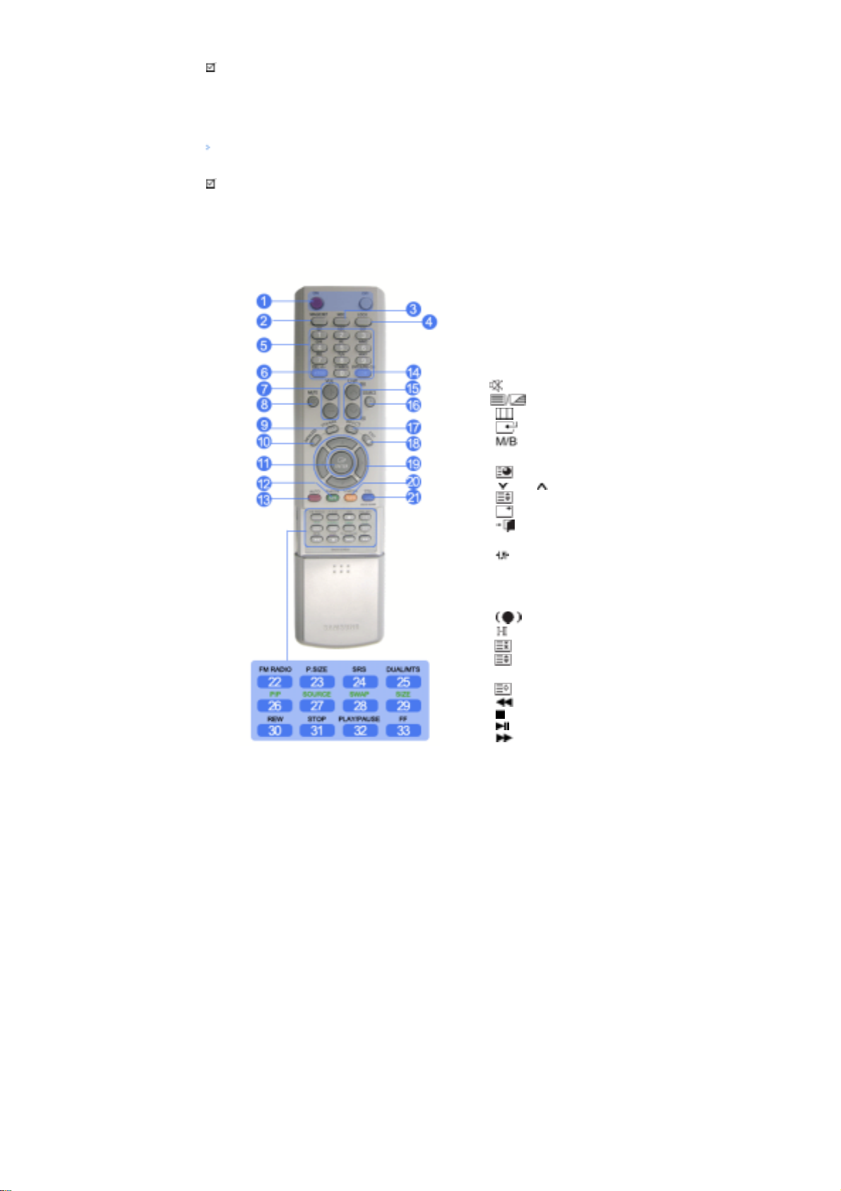
Remote Control
Note
• The performance of the remote control may be affected by a TV or other electronic device operating near
the LCD Display , causing a malfunction due to interference with the frequency.
1. ON / OFF
2. MAGICNET
3. MDC
4. LOCK
5. MagicNet buttons
6.+100 -/--
7. VOL
8. MUTE
9. TTX/MIX
10. MENU
11. ENTER
12. P.MODE
13. AUTO
14. ENTER/PRE-CH
15 . CH/P
16. SOURCE
17. INFO
18. EXIT
19. Up-Down Left-Right buttons
20. S.MODE
21. STILL
22. FM RADIO
23. P.SIZE
24. SRS
25. DUAL/MTS
26. PIP
27. SOURCE
28. SWAP
29. SIZE
30. RE
31. STOP
32. PLAY/PAUSE
33. FF
1) ON / OFF
Turns the LCD Display On/Off.
2) MAGICNET
MagicNet Quick Launch Button.
3) MDC
MDC Quick Launch Button.
4) LOCK
Activates or deactivates all function keys on both the remote control and the LCD Display except for the
Power and LOCK buttons.
5) MagicNet buttons
Used for MagicNet.
• Alphanumeric: Used to enter the Internet address.
• DEL: Functions as the backspace.
• SYMBOL: Used to enter the symbols. (.O_-)
• ENTER: Used to enter values.
6) +100 -/--
Press to select channels over 100.

For example, to select channel 121, press "+100", then press "2" and "1".
- This fuction does not work for this monitor.
7) VOL
Adjusts the audio volume.
MUTE
8)
Pauses (mutes) the audio output temporarily.
This is displayed on the lower left corner of the screen.
The audio resumes if MUTE or - VOL + is pressed in the Mute mode.
9)
10)
Opens the on-screen menu and exits from the menu screen or closes the screen adjustment menu.
11)
Activates a highlighted menu item.
12)
TTX/MIX
TV channels provide text information services via teletext.
- This fuction does not work for this monitor.
MENU
ENTER
P.MODE
When you press this button, current picture mode is displayed on the lower center of the screen.
AV / S-Video / Component : P.MODE
The Monitor has four automatic picture settings that are preset at the factory.
Then push button again to circle through available preconfigured modes.
( Dynamic → Standard → Movie → Custom )
PC/DVI/BNC : M/B (MagicBright™)
MagicBright™ is a new feature providing the optimum viewing environment depending on the contents of
the image you are watching.
Then push button again to circle through available preconfigured modes.
(Entertain → Internet → Text → Custom )
13) AUTO
Adjusts the screen display automatically in PC mode.
By changing the resolution in the control panel, auto function is performed.
ENTER/PRE-CH
14)
Returns to the immediately previous channel.
- This fuction does not work for this monitor.
CH/P
15)
In TV mode, selects TV channels.
- This fuction does not work for this monitor.
SOURCE
16)
Changes the video source.
INFO
17)
The current picture information is displayed in the top left corner of the screen.
EXIT
18)
Exits from the menu screen.
19) Up-Down Left-Right buttons
Moves from one menu item to another horizontally, vertically or adjusts selected menu values.
20)
S.MODE
When pressing this button, the current mode is displayed at the bottom centre of the screen.
The LCD Display has a built-in high fidelity stereo amplifier.
Then press the button again to circle through available preconfigured modes.
( Standard → Music → Movie → Speech → Custom )
21) STILL
Press the button once to freeze the screen. Press it again to unfreeze.
22) FM RADIO
Turns the FM Radio on/off.
In PC/DVI mode, sets the SOUND to FM Radio.
In general Video mode, selects FM Radio, and turns off the screen.
In areas where the signal is weak, noise may occur during FM radio broadcasts.
- This fuction does not work for this monitor.
23) P.SIZE
Press to change the screen size.
24)
SRS
25)
SRS
DUAL/MTS
DUAL-
STEREO/MONO, DUAL l / DUAL ll and MONO/NICAM MONO/NICAM STEREO can be operated
depending on the broadcasting type by using the DUAL button on the remote control while watching TV.
MTS-
You can select MTS (Multichannel Television Stereo) mode.
FM Stereo
- This fuction does not work for this monitor.
26)
Every time you press the button, a PIP screen appears.
27)
Changes the source of the PIP window signal.
Audio Type MTS/S_Mode Default
Mono Mono
Stereo
SAP
Mono ↔ Stereo
Mono ↔ SAP
PIP
SOURCE
Manual Change
Mono
28) SWAP
Swaps the contents of the PIP and main image.
The image in the PIP window will appear on the main screen, and the main screen image will appear in the
PIP window.
SIZE
29)
Switches the PIP Picture Size.
30)
REW
Rewind
31)
STOP
Stop
32)
PLAY / PAUSE
Play/Pause
33)
FF
Fast forward
© 1995~2007 SAMSUNG. ALL Rights Reserved

Mechanical Layout | Monitor Head | Speaker | Installation VESA Bracket | Wall Bracket Installation
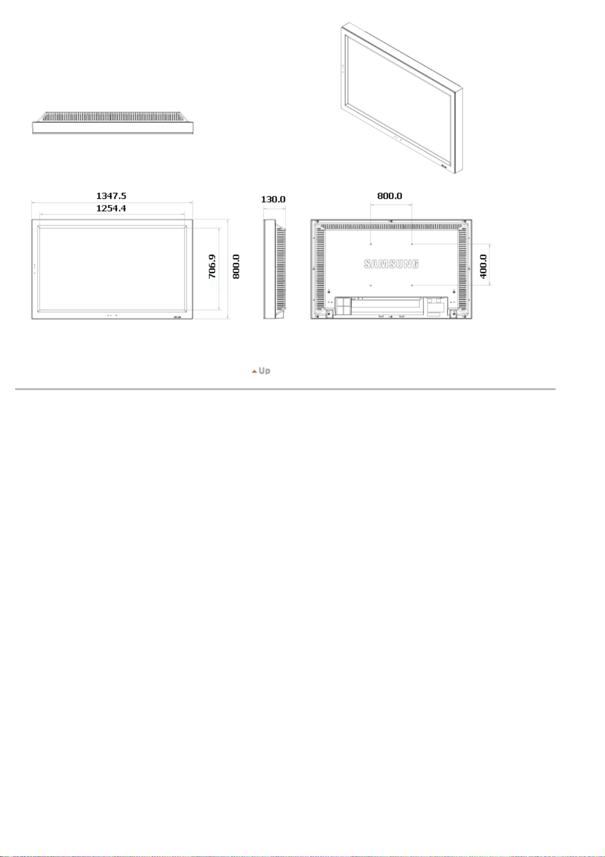
1. Mechanical Layout
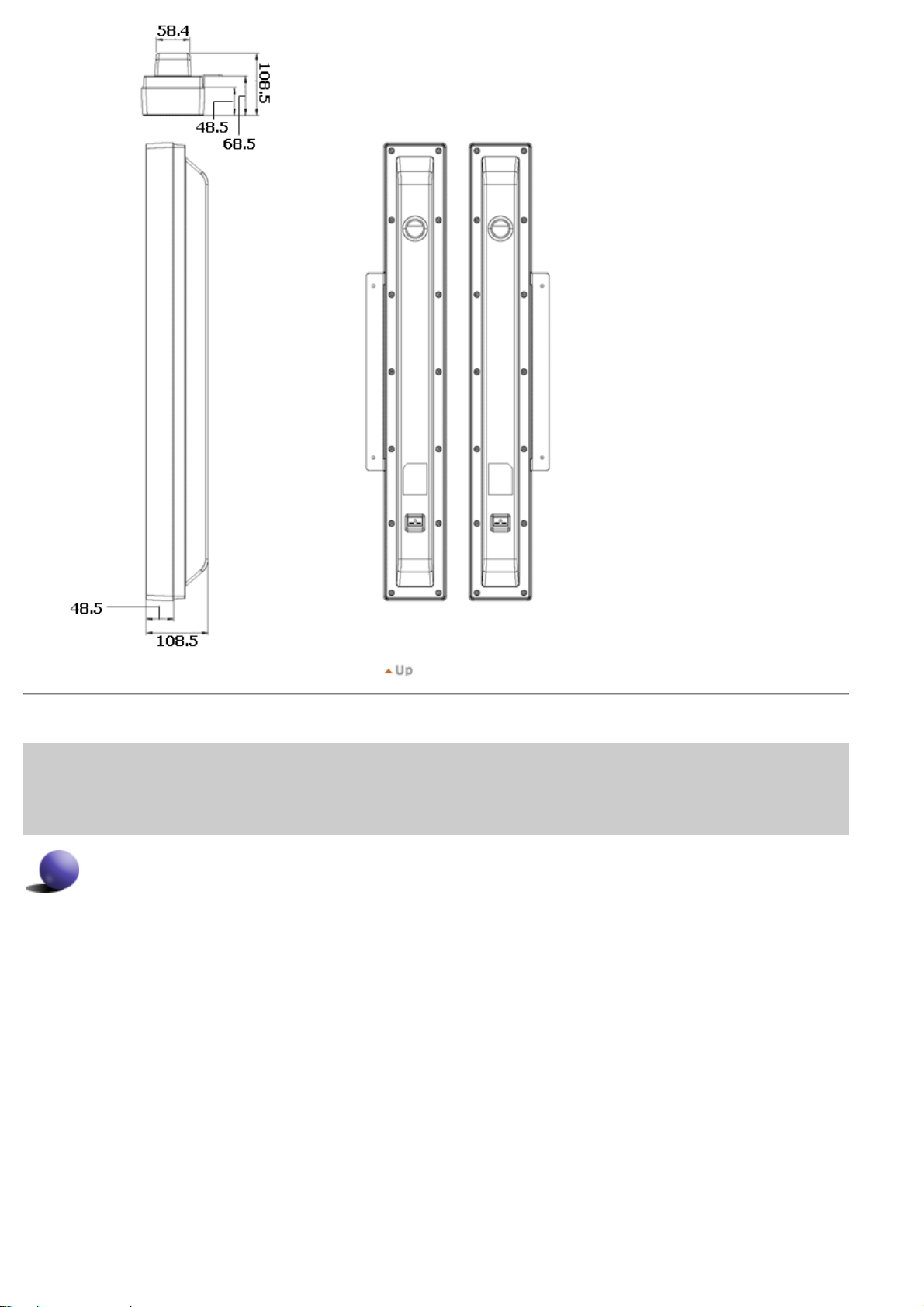
2. Monitor Head
3. Speaker
4. Installation VESA Bracket
When installing VESA, make sure to comply with the international VESA standards.
z
Purchasing VESA Bracket and Installation Information : Please contact your nearest Samsung Distributor to place
z
an order. After your order is placed, installation professionals will visit you and install the bracket.
At least 2 persons are needed in order to move the LCD Monitor.
z
Samsung is not responsible for any product damage or any injury caused by installation at customer's discretion.
z
Dimensions
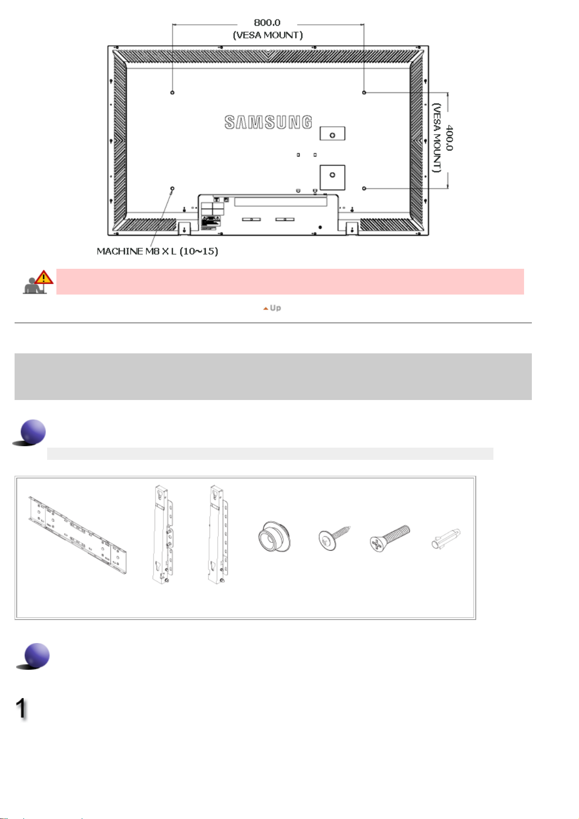
For securing the bracket on a wall, use only machine screws of 6 mm diameter and 8 to 12 mm length.
5. Wall Bracket Installation
Contact a technician for installing the wall bracket.
z
Samsung Electronics is not responsible for any damages to the product or harm to customers when the
z
installation is done by the customer.
This product is for installing on cement walls. The product may not stay in place when installed on plaster or wood.
z
Components
Only use the components and accessories shipped with the product.
`
Wall Bracket
(1)
(Left 1, Right 1)
Wall Bracket Assembly
Hinge
Plastic Hanger
(4)
Screw(A)
(11)
Screw(B)
(4)
Anchor
(11)
Insert and tighten the Captive Screw in the
direction of the arrow.
When done, mount the wall bracket on the wall.
A. Captive Screw
B. Wall Bracket
C. Hinge (Left)
D. Hinge (Right)
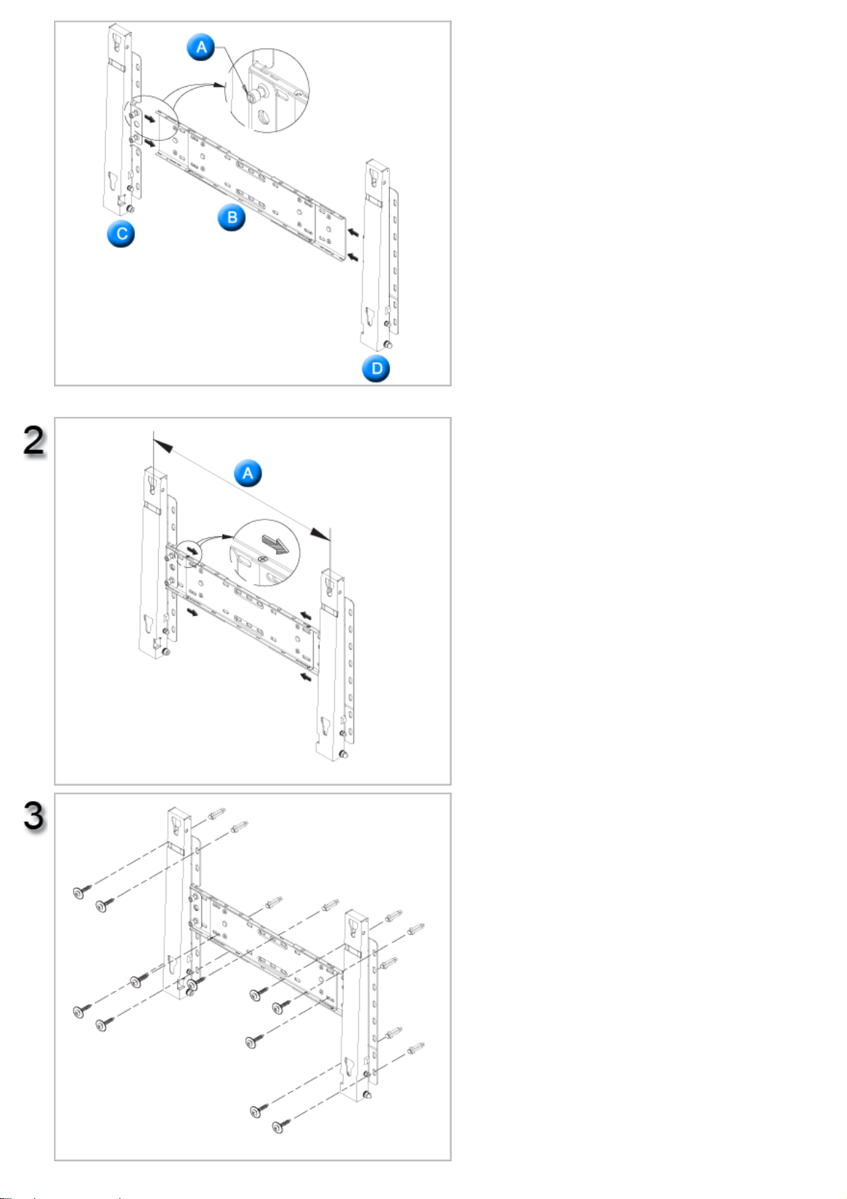
There are two hinges(left and right). Use the correct one.
Before drilling into the wall, check if the length
between the two locking holes at the back of the
product is correct.
If the length is too short or long, loosen all or
some of the 4screws on the wall bracket to adjust
the length.
A. Length between the two locking holes
Check the installation diagram and mark the drill
points on the wall. Use the 5.0 mm bit to drill
holes deeper than 35 mm. Fix each anchor in the
corresponding hole.
Match each of the brackets and hinge holes to
the corresponding anchor holes and insert and
tighten the 11 screws A.

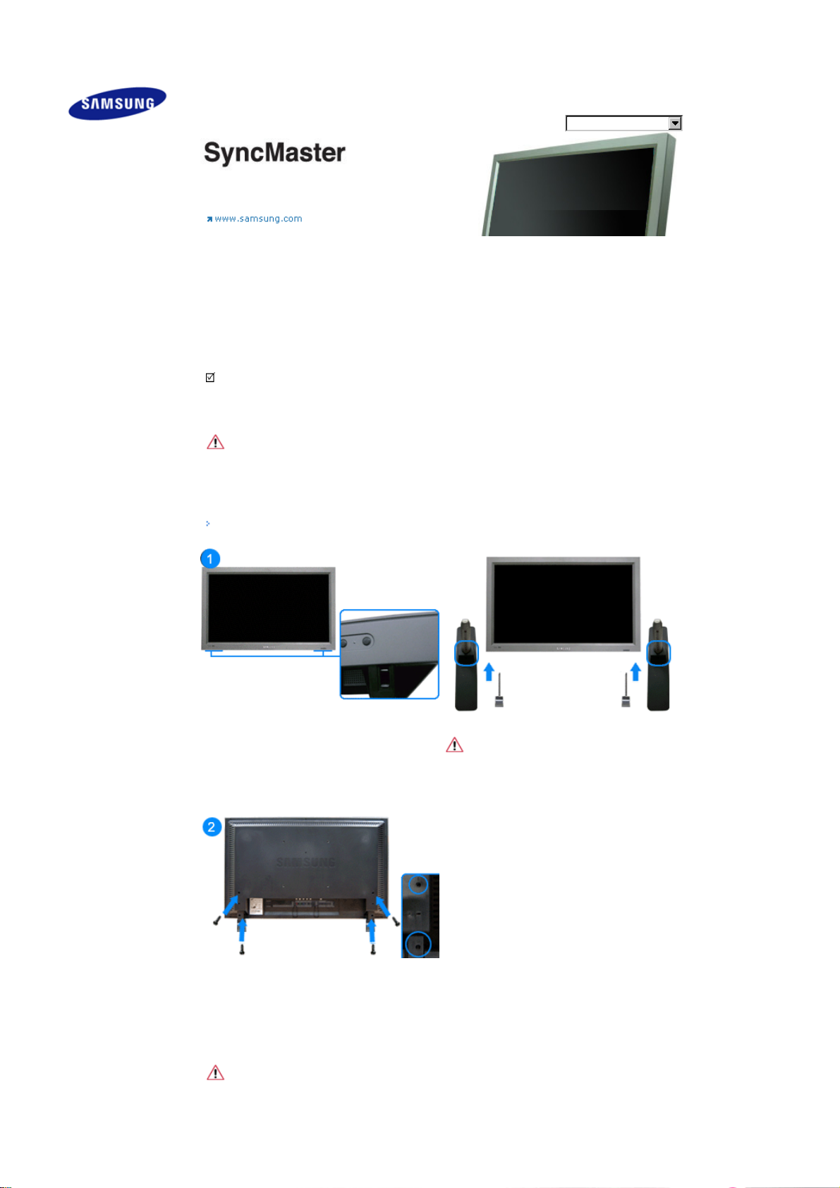
To mount the product on the wall bracket
The shape of the product may vary depending on the model. (The assemblies of the plastic hanger and the
screw are the same)
Remove the 4 screws on the back of the
product.
Insert the screw B into the plastic hanger.
1. Mount the product on the wall bracket and
make sure it is properly fixed to the left and
right plastic hangers.
2. Be careful when installing the product on the
bracket as fingers can be caught in the holes.
3. Make sure the wall bracket is securely fixed to
the wall, or the product may not stay in place
after installation.
Tighten the 4 screws in step 2 (plastic hanger +
screw B)to the rear holes of the product.
Remove safety pin (3) and insert the 4 product
holders into the corresponding bracket holes (1).
Then place the product(2) so that it is firmly fixed
to the bracket. Make sure to re-insert and tighten
the safety pin (3) to securely hold the product to
the bracket.
A. Monitor
B. Wall Bracket
C. Wall

Wall Bracket Angle Adjustment
Adjust the bracket angle to -2°before installing it on the wall.
1. Fix the product to the wall bracket.
2. Hold the product at the top in the center and pull it forward
(direction of the arrow) to adjust the angle.
3. You can adjust the bracket angle between -2°and 15 °.
Make sure to use the top center, and not the
leftor the right side of the product to adjust the
angle.
Safety Instructions
Introduction
Connections
Installing the Stand KIT
Connecting the LCD
Display
Using the Software
Adjusting the LCD Display
Troubleshooting
Specifications
Information
Appen dix
Select Language Main Page
Model
SyncMaster 570DXn
The color and appearance of the product may vary depending on the model, and the product specifications are
subject to change without prior notice for reasons of performance enhancement.
Connections
Installing the Stand KIT
Note
• Only t he supplied bolts should be used.
Caution
Samsung Electronics will not be responsible for damages caused by using a base other than those
specified.
Installing the Semi Stand
Left stand
Right stand
Caution
Make sure to install the stan d with the Caution label
folded backw ards.
1) To protect your product, a Cover Hole is included as an accessory. This protects the hole at the bottom of
the monitor where the stand is inserted. If you install a wall mount kit for your monitor, please place the
Cover Hole over it.
2) Insert it into the hole at the bottom of the monitor. Insert the screw provided with the Cover Hole into the
marked place and fasten it firmly.
Caution
The resolution may differ for each product model. For information on the optimal resolution, refer to the user
manual .
Connecting the LCD Display
Using a Power cord with Earth
In the event of failure, the earth lead may cause electric shock. Make sure to wire the earth lead in
correctly, before connecting the AC power. When un-wiring the earth lead, make sure to disconnect
the AC power in advance.
Note
• AV input devices such as DVD players, VCR's or camcorders as well as your computer can be connected
to the LCD Display. For detailed information on connecting AV input devices, refer to the User Controls
under Adjusting Your LCD Di splay.
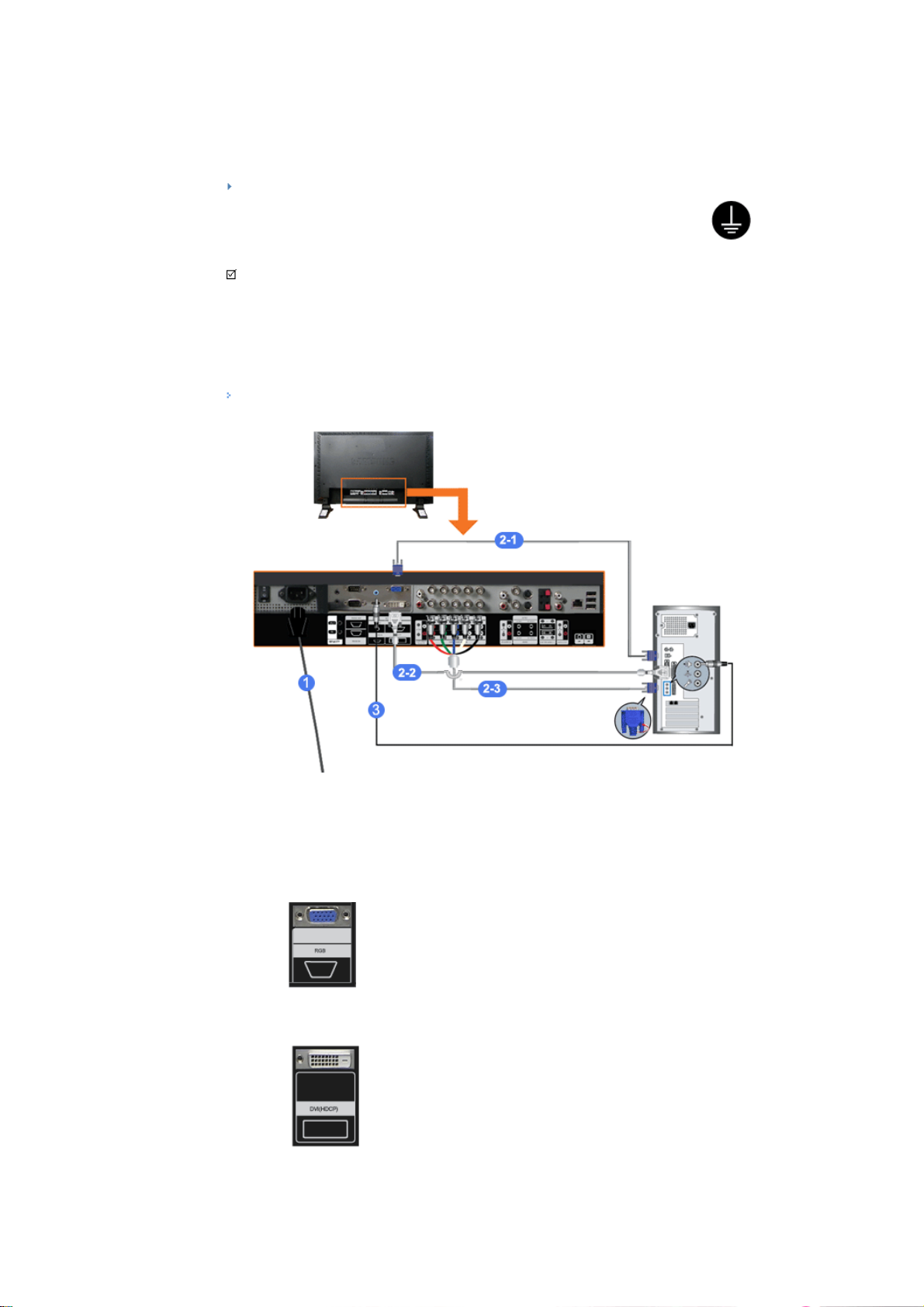
Connecting a Computer
1) Connect the power cord for your LCD Display to the power port on the back of the LCD Display.
Trun on the power switch.
2) There ar e 3 wa ys to connec t the D -sub to your LCD Dis play.
Choose one of the following:
2-1) Using the D-sub (Analog) connector on the video card.
Connect the D-sub to the 15-pin, RGB port on the back of your LCD Display and the 15 pin D-
sub Port on the computer.
2-2) Using the DVI (Digital) connector on the video card.
Connect the DVI Cable to the DVI(HDCP) port on the back of your LCD Display and the DVI port
on the computer.
2-3)
Using the BNC (Analog) connector on the video card.
Connect the BNC Cable to the BNC/COMPONENT IN - R, G, B, H, V ports on the back of your
LCD Display and the 15 pin D-sub Port on the computer.
3) Connect the audio cable for your LCD Display to the audio port on the back of your computer.
Note
• Turn on both your computer and the LCD Display.
Note
• The DVI cable or BNC cable is optional.
Contact a local Samsung Electronics Service Center to buy optional items.
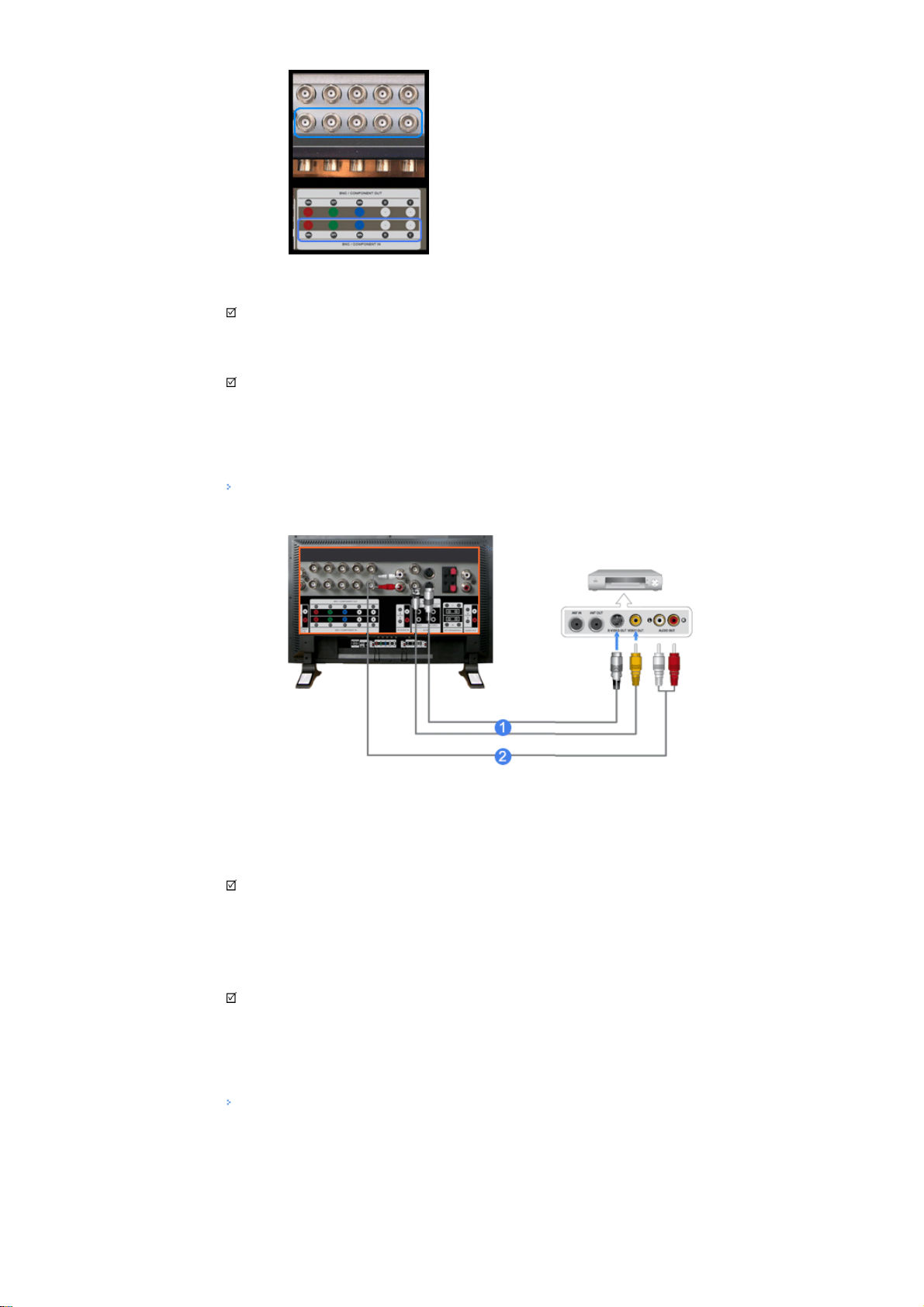
Connecting a VCR
1) AV input devices such as VCRs or Camcorders are connected via the AV IN [VIDEO] or AV IN [S-VIDEO]
of the LCD Display using an S-VHS or BNC cable.
2) Connect the Audio (L) and Audio (R) terminals of a VCR or Camcorders to the LCD Display 's AV AUDIO
IN [L-AUDIO-R] using audio cables.
Note
• Select AV or S-Video for a connected VCR o r Camcorde r using the SOURCE button on the front of the
LCD Display or on the remote control.
• Then, start the VCR or Camcorders with a tape inserted.
Note
• The S-VHS or BNC cable is optional.
Connecting a DVD Player
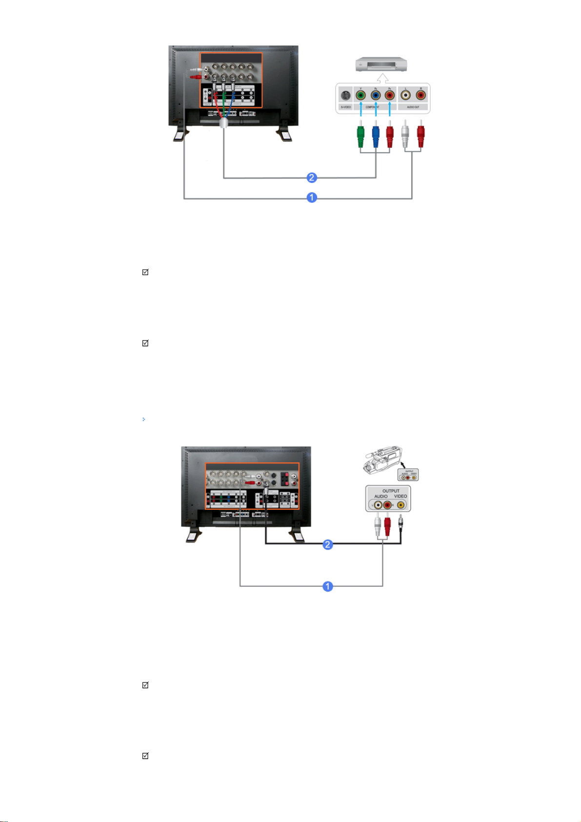
1) Connect a set of audio cables between the COMPONENT AUDIO IN [L -AUDIO-R] on the LCD Display and
the AUDIO OUT jacks on the DVD player.
2)
Connect a Component cable between the BNC/COMPONENT IN - P
and the P
R, Y, P B jacks on the DVD player.
Note
• Select Component for the connection to a DVD player using the SOURCE button on the front of the LCD
Display or on the remote control.
• Then, start the DVD Player with a DVD disc inserted.
Note
• A component cable is optional.
For an explanation of Component video, consult your DVD manual.
R, Y, PB port on the LCD Display
Connecting a Camcorder
1) Locate the A/V output jacks on the camcorder. They are usually found on the side or back of the
camcor der.
Connect a set of audio cables between the AUDIO OUTPUT jacks on the camcorder and the AV AUDIO IN
[L-AUDIO-R] on the LCD Display.
2) Connect a video cable between the VIDEO OUTPUT jack on the camcorder and the AV IN [VIDEO] on the
LCD Display.
Note
• Select AV for the Camcorder connection using the SOURCE button on the front of the LCD Display or on
the remote control.
• Then, start the Camcorders with a tape inserted.
Note

• The audio-video cables shown here are usually included with a Camcorder.
(If not, check your local electronics store.)
If your camcorder is stereo, you need to connect a set of two cables.
Connecting a DTV Set Top Box
Note
• The connections for a typical Set Top Box are shown below.
1)
Connect a Component cable between the BNC / COMPONENT IN - P
R
and the P
2) Connect a set of audio cables between the COMPONENT AUDIO IN [L -AUDIO-R] on the LCD Display and
the AUDIO OUT jacks on the Set Top Box.
Note
• Select Component for the connection to a DTV Set Top Box using the SOURCE button on the front of the
LCD Display or on the remote control.
Note
• For an explanation of Component video, see your Set Top Box owner's manual.
, Y, PB jacks on the Set Top Box.
R, Y, P B port on the LCD Display
Connecting Speakers
Note
• Fasten t he SE T and the spe aker using the scr ews.
* Mount the speaker set without the speaker stand.
 Loading...