How it Works
Log In / Sign Up
Buy Points
How it Works
FAQ
Contact Us
Questions and Suggestions
Users
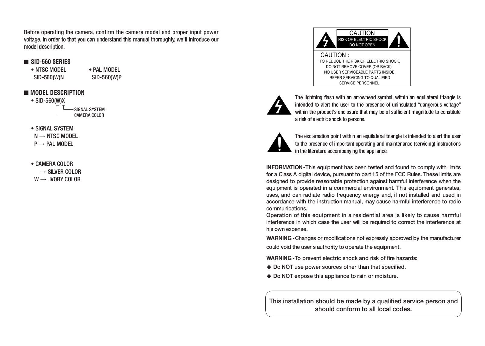
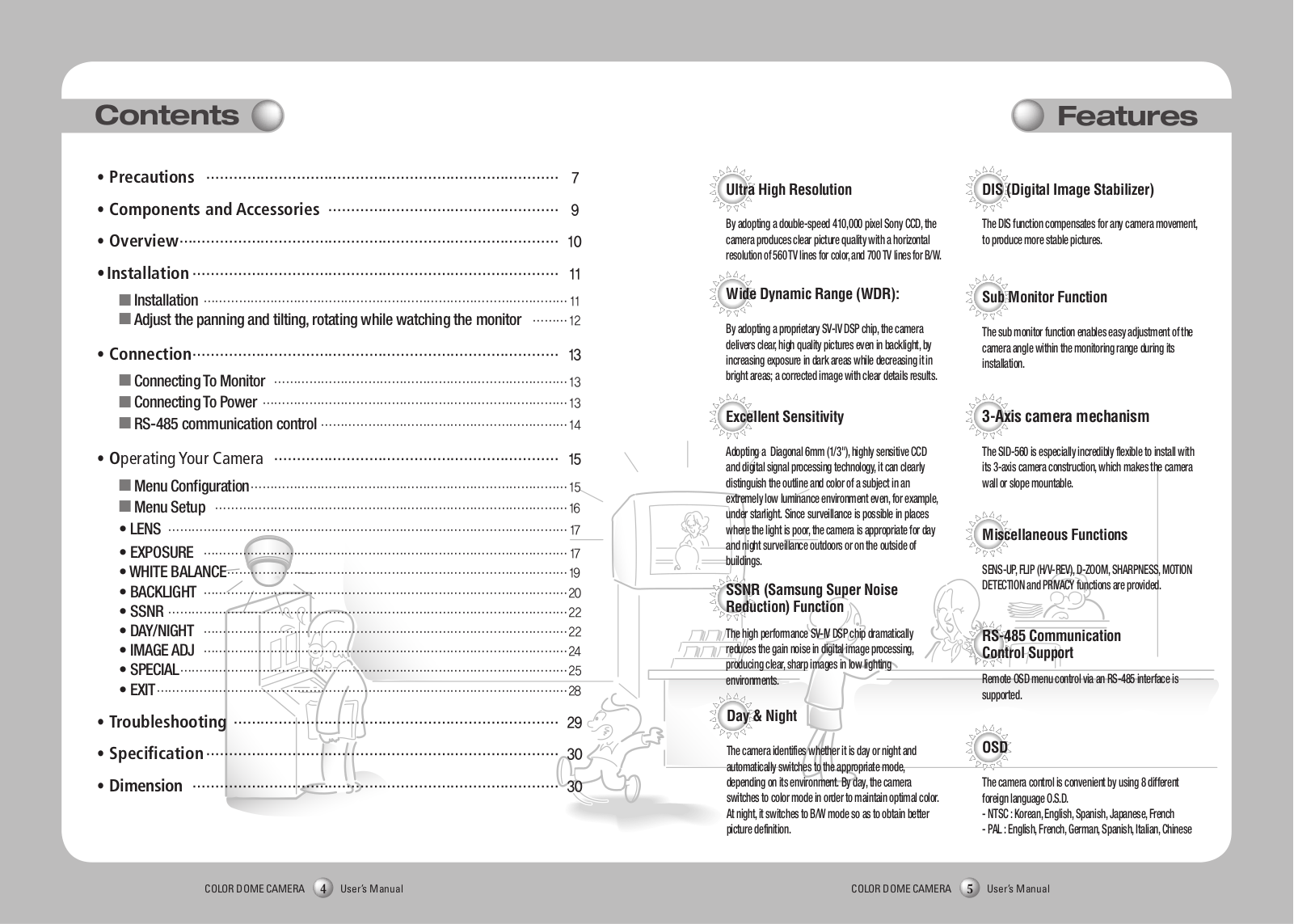
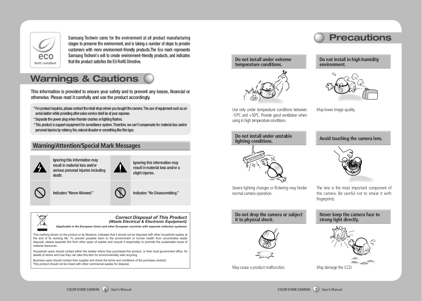
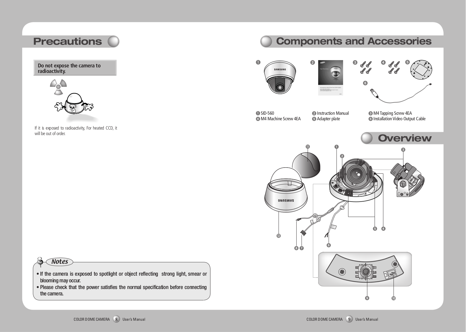
SAMSUNG
Loading...
#
54800THE2/HAC
54T8
550B(T)
550DX
8
550EX
7
550EXN
11
550EX-N-QSG
550N - CLP Color Laser
550N - CLP Color Laser Printer
2
550P
550P5C
550P5C-T05FR
550P7C
550P7C-T05FR
550P7C-T06FR
550s
3
550-SA
2
551S
3
551V
3
55AU7100
55C9000ZFXZA
55EC930V.AEE
55EC930V-ZA
55F6400
55JU7000 Series
55K5100
55KS7500
55KU6000
55KU6000UX
55KU6400
55KU6500UX
55LS03A
55MU6202
55MU6350
55MU6645
55NU8000
55Q65A
55QE55Q6FN
55QN700BT 55"" QLED 8K Dolby Atmos HDMI 2.1
55QN95A
55QN95B
55QN95B 55"" MINILED 4K 100Hz Tizen TV Dolby Atmos HDMI 2.1
55UD
55
55UE
57
550
22
551
2
560TVL
2
560VTFT
56B
5
56E
2
56V
6
570B
10
570BTFT
3
570DTFT
570DX
9
570DXN
6
570DX - SyncMaster - 57"" LCD Flat Panel Display
2
570MPTFT
570P
570S
570S TFT
570V
570VTFT
580S TFT
580TVL
58h5203
58V
591S
11
591SG
2
591V
8
591V/S
592S
592V
5935NX
594MG
2
59E
5
5G CPE
3
5G NR
5N920T
5TH1030
5TH1030N
5TH5896
5TH5896N
5TH731
5TH731N
560
3
570
2
577
578
2
580
590
2
5500
12
5900
5500 5
592-2933
592-29336
2
592-659220
592-659290
Loading...
Loading...
Nothing found
560TVL
User Manual
17 pgs
6.69 Mb
0
User Manual
24 pgs
2.72 Mb
0
Table of contents
Loading...
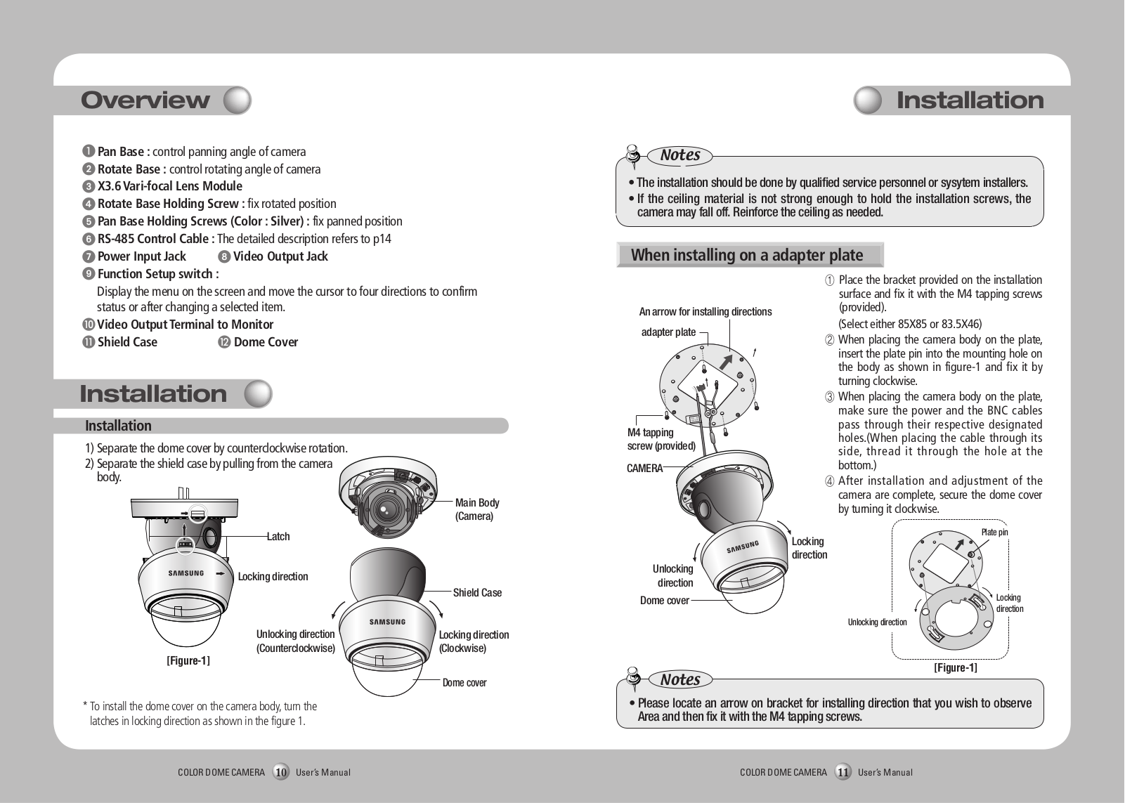
SAMSUNG 560TVL User Manual
...
SAMSUNG User Manual
Download
Specifications and Main Features
Frequently Asked Questions
User Manual
Download
Page 1
Page 2
Page 3
Page 4
Page 5
Page 6
Page 7
Page 8
Page 9
Page 10
Page 11
Page 12
Page 13
Page 14
Page 15
Page 16
Page 17
Loading...
+
hidden pages
Unhide
You need points to download manuals.
1 point = 1 manual.
You can buy points or you can get point for every manual you upload.
Buy points
Upload your manuals
 Loading...