

Samsung 500 User Manual

Enterprise IP Solutions
OfficeServ500
General
Description

Publication Information
Samsung Business Communications reserves the right without prior notice to revise information
in this publication for any reason.
Samsung Business Communications also reserves the right without prior notice to make
changes in design or components of equipment as engineering and manufacturing may warrant.
Disclaimer
Samsung Business Communications is not responsible for errors or problems arising from
customers not installing, programming or operating their Samsung systems as described in this
manual.
Copyright 2005
Samsung Business Communications
All rights reserved. No part of this manual may be reproduced in any form or by any means –
graphic, electronic or mechanical, including recording, taping, photocopy or information retrieval
system – without express written permission of the publisher of this material.
Part No.: 17586 Version 3.0

EU Declaration of Conformity (RTTE)
Samsung Electronics Co., Ltd.
259 Gongdan-Dong, Gumi-City Kyungbuk, Korea, 730-030
(factory name, address)
declare under our sole responsibility that the product
Digital Keyphone System "iDCS500 / OfficeServ500"
to which this declaration relates is in conformity with
RTTE Directive 1999/5/EC ( Annex II )
Low Voltage Directive 73/23/EEC
EMC Directive 89/336/EEC:92/31/EEC
By application of the following standards
.........................................................................................
RTTE : TBR4: November 1995 incorporating TBR4/A1: December 1997
.........................................................................................
LVD: EN60950: 2000 (IEC 60950, Third Edition, 1999)
.........................................................................................
EMC: EN55022 : 1998, EN61000-3-2:1995 Inc A1/A2:1998 + A14:2000*,
.........................................................................................
EN61000-3-3:1995, EN61000-4-2:1995 98, EN61000-4-3:1996,
.........................................................................................
.........................................................................................
EN61000-4-4:1995, EN61000-4-5:1995, EN61000-4-6:1996,
.........................................................................................
EN61000-4-11:1994, AS/NZS3548:1995
(Manufacturer)
Samsung Electronics Co., Ltd
259, Gongdan-Dong, Gumi-City
Kyungbuk, Korea, 730-030
2003-05-19
................................................. .................................................................................
(place and date of issue) (name and signature of authorized person)
(Representative in the EU)
Samsung Electronics Euro QA Lab.
Blackbushe Business Park
Saxony Way, Yateley, Hampshire
GU46 6GG, UK
2003-05-18
................................................. ...............................................................................
(place and date of issue) (name and signature of authorized person)
TE Jang
IS Lee
Tae-eok Jang / General Manager
In-Seop Lee / Manager

Intended Use
This telephone system is intended to provide the user with voice communication between the system
extensions and connection to the public switched telephone network by digital or analogue links.
The telephone system may be provided with the ability to communicate with local computer networks to
provide CTI functions and features. In this case, it is capable of passing information to the computer network
via a specified link.
The system is powered by mains voltage and can optionally be powered by batteries. Details of all
connections and power arrangements are provided in the instructions for use. It should not be used in any
other way.

Preface
About Your Samsung OfficeServ500 System
The Samsung OfficeServ500 system comprises three separate versions: ‘S’ (small), ‘M’ (medium) and ‘L’ (large). They are defined by their size and functionality—the larger systems
providing support for more telephone ports and features than the smaller systems—and are
designed to suit a wide range of commercial and business activities.
About This Manual
This guide provides an overview of the OfficeServ500, including system structure and hardware, features and facilities, and specifications. The guide consists of the following chapters.
1 Introduction to OfficeServ500
2 Hardware Descriptions
3 Specifications
4 Business Features Package
5 Hotel Features
Supporting Documents
The following guides and manuals are also available for your system. Yo u may need to refer
to one or more of them during installation. You should have them available for guidance when
your system is fully installed and operational.
y
Samsung OfficeServ500 Installation Guide
This guide provides information for installing your system and connecting station and optional equipment.
y
Samsung Combined Systems Programming Manual
The system is configured using MMC (Man Machine Communication) programming. The
installer or system administrator programs the system using MMCs from a digital display
keyphone. This manual describes each MMC and how it is used.
y
Samsung OfficeServ System Administration Guide
This guide provides easy to follow instructions for the system administrator on setting up
the features most commonly required by telephone users.
y
Samsung Digital Keyset, Internet Phone & Single Line Telephone User Guides
Refer to the appropriate user guide for each type of telephone connected to your system.
These may include Samsung DCS (Euro) digital keysets, OfficeServ500 series digital keysets and IP phones, iDCS series digital keysets, and single line telephones.
p
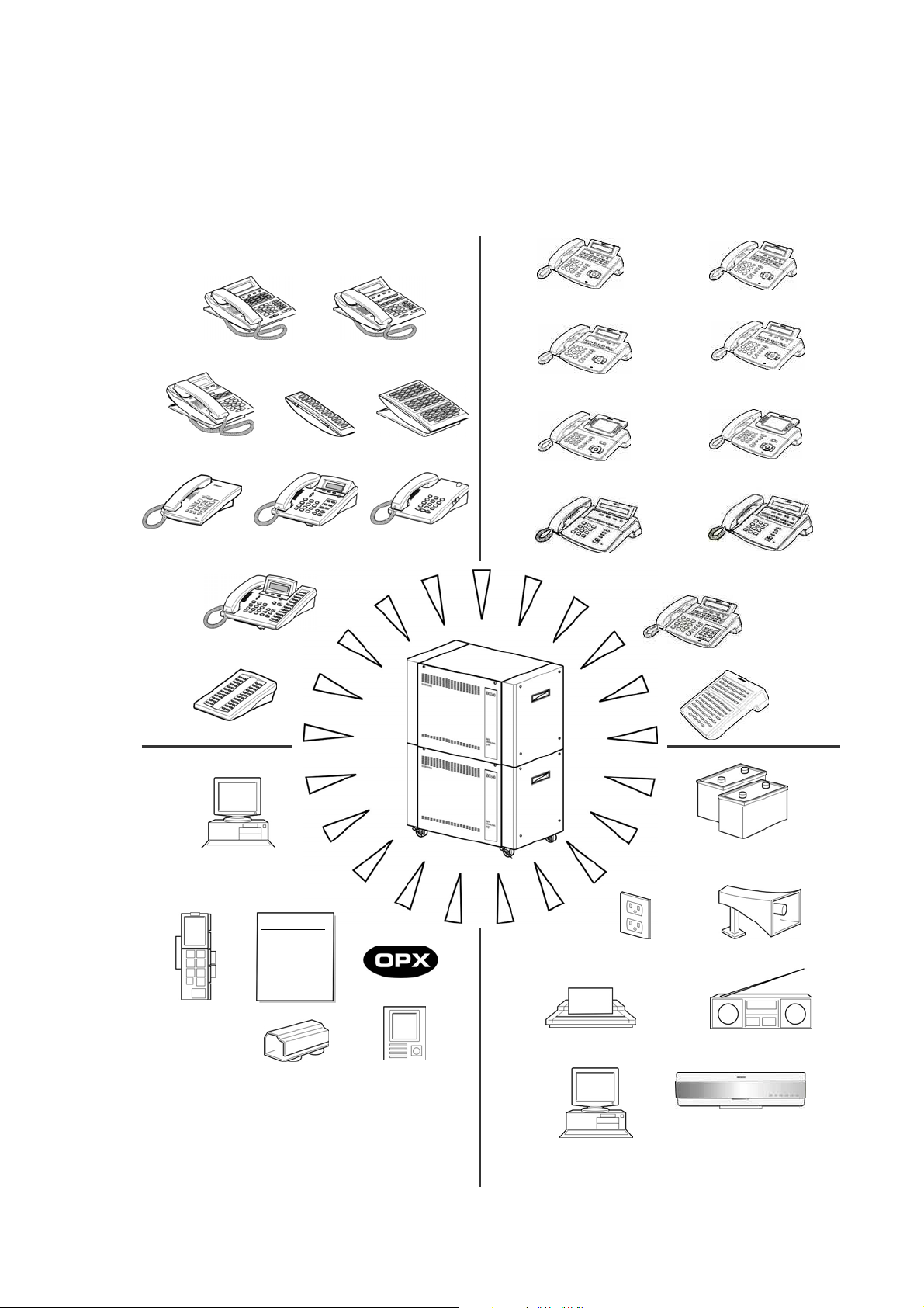
OfficeServ General System Diagram
iDCS Series and DCS Euro Keysets 5000 Series Digital Keysets and IP Phones
iDCS 28D Keyset iDCS 18D Keyset
iDCS 64B AOM iDCS 14B AOM iDCS 8D Keyset
Single Line Telephone 6B LCD (Euro) Keyset DS-2100B Keyset
DS-5021D (21B, 2-Line LCD)
DS-5014D (14
DS-5012L (12B, Large LCD)
DS-5007S (7B, 2-Line LCD)
B, 2-Line LCD) ITP-5014D (14B, 2-Line LCD)
DS-5014S (14B, 2-Line LCD)
ITP-5021D (21B, 2-Line LCD)
ITP-5012L (12B, Large LCD)
LCD 12B/24B (Euro) Keyset
DS-5038S (38B, 2-Line LCD)
48 Button AOM
64B AOM
Computer
System programming
Remote programming
uter telephony integration
Com
Loop start
DID
Tie Iine
E1
ISDN PRI/BRI
Cadence &
SVMi-8/16
voice mail &
auto attendant
Telephone Lines
Off Premises Extension
Loud Bells
Door phones
110/220V AC
SMDR
Printer or call accounting system
48VDC Battery
Backup
External paging zones
External music sources
Voice mail/auto
attendant systems
Wireless LAN Service

Contents
Chapter 1 Introduction to OfficeServ500 ...................................... 1-1
Terminology...........................................................................................................................1-1
General Description ............................................................................................................ 1-1
Sizes and Configurations .................................................................................................... 1-2
Differences Between OfficeServ500 Systems ..................................................................... 1-3
Technology .......................................................................................................................... 1-6
Programming ....................................................................................................................... 1-6
Chapter 2 Hardware Descriptions .................................................. 2-1
System Cabinets ................................................................................................................. 2-1
Common Control Cards ...................................................................................................... 2-2
Processor Cards .................................................................................................................................... 2-2
Processor Card Daughterboards ........................................................................................................... 2-4
SmartMedia Cards ................................................................................................................................. 2-6
Input–Output Module (IOM) Board ........................................................................................................ 2-6
Modem Daughterboard .......................................................................................................................... 2-6
Interface Cards .................................................................................................................... 2-6
Trunk Cards ........................................................................................................................................... 2-6
Station Cards ......................................................................................................................................... 2-8
Other Cards ......................................................................................................................................... 2-10
Station Equipment ............................................................................................................. 2-11
OfficeServ 5000 Series Keysets .......................................................................................................... 2-11
OfficeServ 5000 Series Add-On Module (DS-5064B) .......................................................................... 2-14
OfficeServ 5000 Series Keyset Daughterboards ................................................................................. 2-15
DCS Series (Euro) Keysets ................................................................................................................. 2-15
DCS Series Add-On Module (48B)..................................................................................................... 2-17
DCS Series Keyset Daughterboards ................................................................................................... 2-17
iDCS Series Keysets ........................................................................................................................... 2-18
iDCS Series Add-On Modules ............................................................................................................ 2-19
iDCS Series Keyset Daughterboards................................................................................................... 2-20
Door Phone Interface Module (DPIM) and Door Phone........................................................................2-20
Chapter 3 Specifications ................................................................. 3-1
Electrical Specifications (PSU-B) ........................................................................................ 3-1
Dimensions and Weights .................................................................................................... 3-1
Environmental Limits ........................................................................................................... 3-1
Cable Requirements ........................................................................................................... 3-2
Reserve Power Duration Estimates .................................................................................... 3-2
System Tones ...................................................................................................................... 3-4
Keyset LED Indications ....................................................................................................... 3-5
Chapter 4 Business Features Package .......................................... 4-1
System Features ................................................................................................................. 4-1
System Feature Descriptions ................................................................................................................ 4-2
Station Features ................................................................................................................ 4-25
Station Feature Descriptions ............................................................................................................... 4-25
Display Features ............................................................................................................... 4-33
Display Feature Descriptions ................................................................................................................4-33
i

ii
Contents
Sample Keyset Displays ....................................................................................................4-37
Call Handling .........................................................................................................................................4-37
Caller ID Displays ................................................................................................................................ 4-38
UCD Displays ...................................................................................................................................... 4-39
Sample SMDR Printout...................................................................................................... 4-40
Sample UCD Report ......................................................................................................... 4-41
UCD Call Statistics ............................................................................................................ 4-42
UCD Agent Statistics ......................................................................................................... 4-44
Sample Traffic Report ....................................................................................................... 4-45
Traffic Report Overview ..................................................................................................... 4-46
Sample Alarm Report ........................................................................................................ 4-52
Chapter 5 Hotel Features ................................................................. 5-1
Features .............................................................................................................................. 5-1
Feature Descriptions ............................................................................................................................. 5-1
List of Figures
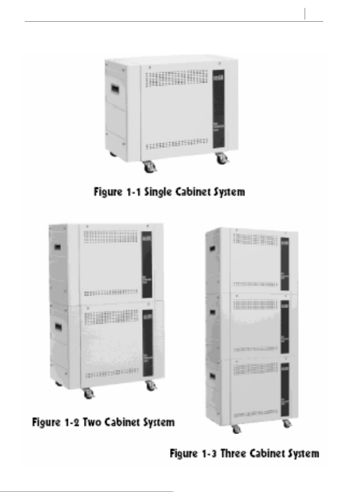
Figure 1-1 OfficeServ500 Single Cabinet System ............................................................................... 1-7
Figure 1-2 OfficeServ500 Two Cabinet System .................................................................................. 1-7
Figure 1-3 OfficeServ500 Three Cabinet System ................................................................................ 1-7
Figure 2-1 ITP-5014D Keyset............................................................................................................. 2-11
Figure 2-2 ITP-5021D Keyset............................................................................................................. 2-12
Figure 2-3 DS-5014D Keyset ..............................................................................................................2-12
Figure 2-4 DS-5021D Keyset ..............................................................................................................2-13
Figure 2-5 DS-5007S Keyset ..............................................................................................................2-13
Figure 2-6 DS-5014S Keyset ..............................................................................................................2-13
Figure 2-7 DS-5038S Keyset ..............................................................................................................2-14
Figure 2-8 ITP-5012L Keyset ..............................................................................................................2-14
Figure 2-9 DS-5012L Keyset...............................................................................................................2-14
Figure 2-10 DS-5064B AOM .................................................................................................................2-15
Figure 2-11 LCD 24B Euro Keyset........................................................................................................2-16
Figure 2-12 LCD 12B Euro Keyset........................................................................................................2-16
Figure 2-13 LCD 6B Euro Keyset..........................................................................................................2-16
Figure 2-14 6B Basic/Enhanced Model Keyset ....................................................................................2-17
Figure 2-15 DS-2100B Keyset ............................................................................................................. 2-17
Figure 2-16 DCS 48-Button AOM......................................................................................................... 2-17
Figure 2-17 iDCS Series 28D Keyset....................................................................................................2-18
Figure 2-18 iDCS Series 18D Keyset....................................................................................................2-19
Figure 2-19 iDCS Series 8D Keyset......................................................................................................2-19
Figure 2-20 iDCS 64-Button AOM.........................................................................................................2-20
Figure 2-21 iDCS 14-Button AOM.........................................................................................................2-20
Figure 2-22 Door Phone Interface Module (DPIM) and Door Phone ....................................................2-21

Chapter 1 Introduction to OfficeServ500
This chapter contains the following sections:
y Terminology
y General Description
y Sizes and Configurations
y Differences Between OfficeServ500 Systems
y Technology
y Programming
Terminology
The Samsung OfficeServ500 digital telephone system is designed for medium-sized businesses. The system is configured as an ‘S’, ‘M’ or ‘L’ system: ‘S’ and ‘M’ systems are single
cabinet systems while ‘L’ systems have a higher capacity and can be expanded to two or
three cabinets. It is possible to easily upgrade from an ‘M’ to an ‘L’ system by changing the
software. All systems are controlled by a main control processor card, the MCP2.
1-1
General Description
All systems can operate with the functionality of a square key system, PABX or a combination of both (hybrid). They employ DSP (Digital Signal Processors) digital technology.
A variety of interface cards are available that allow connection to the public telephone network or to private networks. These are generally referred to as trunk cards. Three types of
telephone can be connected to the system: proprietary digital phones (keysets) which connect to digital line interface cards (DLI); standard telephones (generally called single line telephones, or SLTs) which connect to single line interface cards (SLI); and Internet (IP) phones.
In addition, DLI station ports are used to connect peripheral devices such as door phones
and add-on modules. Miscellaneous circuits are provided to allow such optional features as
external paging, music-on-hold, background music, and common audible devices. All interface cards are encased in an anti-static plastic enclosure and some can be inserted or removed with power on to eliminate unnecessary service interruptions while performing maintenance.
All keysets have a single PCB with surface-mounted components assuring the highest product quality and long life. Samsung’s customary large, easy-to-read displays and key LEDs
make them much easier to use. In many instances, sophisticated features are made simple
through the use of friendly display prompts or programmable feature keys.
Expanding the system is both economical and easy. You can begin with a single cabinet configured as a basic Key Service Unit (KSU) and then add up to two more cabinets as your
business grows. Its low- and medium-density card design allows greater flexibility when configuring a system for the right combination of lines and stations. A removable software cartridge (SmartMedia card) makes it convenient to upgrade to future feature packages.

1-2
Chapter 1
Introduction to OfficeServ500
Sizes and Configurations
OfficeServ500 is a fully modular system. A basic system comprises a single cabinet configured as a KSU with interface cards and keysets. Up to two additional (expansion) cabinets
can be connected to a single cabinet ‘L’ system to enhance its abilities. A fully expanded ‘L’
system (three cabinets) using TEPRI cards can have a maximum of 406 lines or 360 stations.
Without the TEPRI cards, the maximum number of lines is 208 and the maximum number of
stations is 360.
The system supports a maximum of 542 ports and 240 IP extensions. Each cabinet supports
one or two PSU-B power supply units. One PSU-B supports up to 56 stations; two PSU-Bs
support up to 120 stations. Both power supply units are connected to the DC bus for external
battery backup. Each cabinet also has four Digital Signal Processor (DSP) channels for use
as DTMF receivers/senders or tone detectors.
NOTE: For a full description of each card discussed in this section, refer to Chapter 2,
Hardware Descriptions.
Single Cabinet System (Basic KSU)
A single cabinet system (Figure 1–1) has a number of universal card slots, a main processor
card (MCP2) slot and two power supply slots. ‘S’ systems have six universal slots, while ‘M’
and ‘L’ systems have nine universal slots. On ‘L’ systems, the MCP2 card must be equipped
with an ESM daughterboard.
The first power supply slot must be occupied by a PSU-B to supply sufficient power to all 10
slots (nine universal and a processor slot) and support up to 56 stations. A second PSU-B
may optionally occupy the second power supply slot. Station or trunk (line) cards can be installed in any of the universal slots. The TEPRI and 8BSI cards must be installed in slots 1, 2
or 3. This allows a maximum of 120 stations of any kind or 138 lines in a single cabinet system. Without TEPRI cards, the maximum number of CO lines in the basic KSU is 72.
Two Cabinet System
In a two cabinet system (Figure 1–2), the Signal Control Processor (SCP2) card must be installed in slot 9 of the KSU. This card provides an intermediate level of processing to control
the first cabinet, thereby freeing resources on the MCP2 to control the entire system. Adding
the SCP2 card therefore reduces the number of universal card slots in the KSU to eight. The
expansion cabinet must also have a Local Control Processor (LCP2) card installed.
All processor cards have provision for installing three daughterboards. The MCP2 card must
be equipped with an ESM daughterboard. Any other type of daughterboard you need can be
installed on the MCP2, SCP2 or LCP2 card.
A two cabinet system has 17 universal card slots. This allows a maximum of 240 stations or
268 lines when using TEPRI cards. Without TEPRI cards, the maximum number of lines is
136 while the maximum number of stations remains at 240. The LCP2 card controls the expansion cabinet in a similar manner to the SCP2 in the KSU, and connects to the MCP2 via a
25-pair cable. The LCP2 card resides in dedicated slot 10 of the expansion cabinet and
therefore does not deplete the number of universal card slots.
NOTE: The first power supply slot in each cabinet must be occupied by a PSU-B to supply
sufficient power to all 10 slots (nine universal and a processor slot) and support up to 56
stations. A second PSU-B may optionally occupy the second power supply slot.
Three Cabinet System
In a fully expanded three cabinet system (Figure 1–3), there are 26 universal card slots. This
allows a maximum of 360 stations or 406 lines when using TEPRI cards. Without TEPRI
cards, the maximum number of lines is 208 and the maximum number of stations is 360. The
third (expansion) cabinet is also controlled by an LCP2 card in a similar manner to that in the
second (expansion) cabinet and connects to the second cabinet’s LCP2 card via a 25-pair
cable. This processor resides in dedicated slot 10 and therefore does not deplete the number
of universal card slots. Additionally, the MCP2 card must be equipped with an ESM daughterboard.
NOTE: The first power supply slot in each cabinet must be occupied by a PSU-B to supply
sufficient power to all 10 slots (9 universal and a processor slot) and support up to 56
stations. A second PSU-B may optionally occupy the second power supply slot.
1-3
Differences Between OfficeServ500 Systems
The following tables describe the different configurations allowed for each system—cabinets,
interface cards, daughterboards, and so on.
Table 1-1 Allowed System Configurations
Classification Component
SYSTEM
(see Chapter 2
for a description
of interface cards
and daughterboards)
CABINET
MCP2
SCP2
LCP2
IOM g g g
SCM
MFM
RCM2
MISC g g g
ESM
MODEM
MGI2 g g g
MGI3 g g g
OfficeServ500
S M L
g g g
g g g
g
g
g g g
g g g
g g g
g
g g g
Remarks
Not installed in expansion cabinets.
Common resource daughterboards are installed on MCP2 card for ‘S’ and ‘M’ versions,
and on MCP2 / SCP2 / LCP2 cards for ‘L’
version.
Used for line expansion
Installed on IOM
Supports G.711, G.729, T.38, H323, SIP
Supports G.711,G.729, G.723, T.38, H323, SIP
MGI3D/ITM3D
g g g
8 additional channels in MGI3

1-4
Chapter 1
Introduction to OfficeServ500
Table 1-1 Allowed System Configurations (Contd)
Classification Component
DECT
Keyset
DTRK
A TRK
Subscriber
Service
SmartMedia
Card
Wireless IP
DBS
8BSI g g g
OD8000
DPIM
DS-5012L
DS-5021D /
5014D
DS-5007S /
5014S / 5038S
ITP-5012L
ITP-5021D /
5014D
TEPRI
BRI
TRK_B
8TRK
AC15
16SLI
16MWSLI
8SLI
8MWSLI
16DLI
DLI
AA
SVMi-8
SVMi-16
VDIAL
System software
WLI g g g
WBS24 (Combo)
WBS24 (Basic)
WIP-5000M g g g Wireless IP handset
OfficeServ500
S M L
g g g
g g g
g g g
g g g
g g g
g g g
g g g
g g g
g g g
g g g
g g g
g g g
g g g
g g g
g g g
g g g
g g g
g g g
g g g
g g g
g g g
g g g
g g g
g g g
g g g
g g g
Remarks
DECT Base Station
Accommodates eight DECT Base Stations
(DBS) per card
Max. 1 card for ‘S’ & ‘M’ systems
Max. 3 cards for ‘L’ systems
DECT handset
Large LCD
2-line LCD
2-line LCD
Large LCD IP phone
2-line LCD IP phone
16 ports
Message Waiting function
8 ports
Message Waiting function
Supports keyset daughterboards
Separate management for ‘S’, ‘M’ and ‘L’
Wireless LAN Access Point interface (Combo
type only)
Wireless IP Access Point for use with the WLI
card
Wireless IP Access Point for use with the MGI
card
Table 1-2 Slots, Cards and I/O ports
Item S or M Version L V ersion
1-5
Cabinets SIngle cabinet
Universal Slots 16 channel : 6 (‘M’), or 3 (‘S’)
32 channel : 3
Basic Cards Installed MCP2 card
PSU-B card
Daughterboards SCM: Max. 1
RCM2: Max. 1
MISC: Max. 1
TOTAL: Max. 3
Input/Output Ports (IOM card)
Two SIO ports ( max. 38.4Kbps)
One, two or three cabinets
16 channel : Max. 17
32 channel : Max. 9
MCP2, SCP2 and LCP2 card,
ESM daughterboard, PSU-B card
SCM: Max. 1
MFM: Max. 3
RCM2: Max. 3
MISC: Max. 3
TOTAL: Max. 10
Table 1-3 Specifications
Item Specifications
Supported
Cards
C.O TRK-B, 8TRK, AC15, TEPRI, BRI
Station SLI, 8SLI, 16SLI, 8MWSLI, 16MWSLI, DLI, 16DLI
Service AA, SVMi-8, SVMi-16, VDIAL, MGI2, MGI3
Daughter
Board
Service IOM, MDF, PFT
Additional Equipment Hold/Background music source
Station Equipment
ESM, MISC, SCM, MFM, RCM2, MGI3D/ITM3D, MODEM
External paging device
Loud bells
PC for programming (PCMMC)
PC for SMDR, PC for Computer-Telephony Integration (CTI)
● Standard telephone (SLT)
● DPIM
● Digital Keysets (Euro, iDCS)
● Large LCD Keyset DS-5012L, ITP-5012L
● 2-Line Keysets DS-5021D/5014D, DS-5007S/5014S/5038S, ITP-5021D/5014D

1-6
Chapter 1
Introduction to OfficeServ500
Technology
Memory
The system operates using stored program control. The program is stored on a SmartMedia
card inserted into the Main Control Processor (MCP2) card.
MCP2 Card
The card contains a minimum of 16 Megabytes (MB) of NAND-Flash memory providing a
backup customer database and a backup operating program. The system boots from a 512
kbyte boot ROM and downloads the operating program into 64MB of DRAM on the MCP2
card. The customer database is stored in 4MB of non-volatile SRAM for a single cabinet system.
Microprocessors
The system uses distributed processing. Its primary processor is a 32-bit Motorola MC68302
operating at a clock speed of 80MHz on the MCP2 card. This provides all the processing
necessary for a single cabinet system. In a multiple cabinet system the secondary level of
processing is on the SCP2 card for the first cabinet and on the LCP2 cards for the expansion
cabinets. These secondary processors are MC68302 processors running at 16 MHz and provide local control of each cabinet. The tertiary level of processing is done in the keysets. The
digital keysets use a Hitachi H8 processor for data communication within the system.
Programming
The system is self-configuring. This means that immediately after switching on, the system
reads the types and locations of all installed interface cards and keysets and assigns default
data to them. This data provides for system operation within a few minutes of power on. All
trunks and stations are assigned three- or four-digit numbers according to the settings of the
switches on the MCP2 card and the default numbering plan. This numbering plan is flexible
and may be changed to suit customer requirements during installation.
The system can be programmed from any LCD display keyset without interrupting system
operation. There are three levels of programming: technician (or system), customer and station. The technician level has access to all programs and can allow the customer access to
system programs as needed. Technician and customer access levels are controlled by different security passcodes and access procedures.
The system also allows the use of a proprietary computer program called PCMMC. This permits a technician to program the system using a personal computer. PCMMC can be used
on-site to modify the customer database or to download (save) the entire customer database
to a file. This file can then be saved as a backup and be uploaded when required to restore
the database.
Using modems, PCMMC can access the system remotely (off-site) to make database
changes or perform uploads or downloads of the customer database as if the technician were
on-site.
1-7

Chapter 2 Hardware Descriptions
This chapter describes the hardware for OfficeServ500 systems, as follows:
y System Cabinets
y Common Control Cards
y Interface Cards
y Station Equipment
System Cabinets
2-1
System cabinets are made of metal and are therefore robust. They are used as the main
cabinet / key service unit (KSU), or as expansion cabinets in ‘L’ systems where they can be
stacked up to three high to achieve maximum capacity. Cabinets may be wall mounted or—
for multiple cabinet systems—may be mounted in a standard 19-inch equipment rack after
removal of the side panels and their supporting brackets. Each cabinet comprises the
following:
y Eight universal interface card slots (or six for ‘S’ systems)
y One dual-purpose interface card / signal processor slot (see Sizes and Configurations
Chapter 1)
y One processor card slot
y Two power supply slots
y One IOM board slot for the main cabinet/KSU (see Input-Output Module (IOM) Board
this chapter).
y AC power connector
in
in
y DC power (Battery Backup) connector
NOTE: The first power supply slot must be occupied by a PSU-B power supply to supply
sufficient power to all 10 slots (8 interface, one dual purpose and one processor slot). A
second PSU-B may optionally occupy the second power supply slot.

2-2
Chapter 2
Hardware Descriptions
Common Control Cards
PROCESSOR CARDS
The system requires a processor card (or cards) in order to operate. In a single cabinet
system, only the Main Control Processor (MCP2) card is required. (See the Technology
section in Chapter 1 for a description of how Main Control Processor cards work.) When the
system is expanded to two or three cabinets, an SCP2 card is also required in the main
cabinet to assist the MCP2. Each expansion cabinet requires its own Local Control
Processor (LCP2) card. These cards are described here.
Main Control Processor Card (MCP2)
The features of the MCP2 card are described in the table below.
Table 2-1 MCP2 Card Features
Item Description
Processor 32 bit, 80 MHz
SIO Port
(Asynchronous)
SmartMedia Card 16 MB
SRAM Basic : 4 MB
SDRAM Basic : 64 MB
HDLC Port for IPC Basic: Installed
Time switch Basic : 512x512 Ch.
Daughterboard
Mounting
The MCP2 is installed in the dedicated processor slot 10 of the first cabinet and has positions
for three daughterboards (refer to table below).
The first daughterboard position (LOC1) can support one of four types of daughterboard: a
Multi-Frequency Module (MFM), a Switch/Conference Module (SCM), an R2/CID Module
(RCM2), or an Expanded Switching Module (ESM). The ESM must be installed in this
position on the card in a multiple cabinet system, or in a single cabinet system
running ‘L’ version software.
Basic 2 port (SIO2,SIO3)
Expansion : 1024x1024 Ch.
LOC1, LOC2, LOC3
The second daughterboard position (LOC2) can support the MFM, the SCM, or the RCM2.
The third daughterboard position (LOC3) can support an MFM, SCM, RCM2, or
Miscellaneous (MISC) daughterboard.

MAIN CONTROL PROCESSOR (MCP2) DAUGHTERBOARD CAPABILITIES
Position Type of Daughterboard Allowed
LOC1 MFM, SCM, RCM2 and ESM*
LOC2 MFM, SCM, RCM2
LOC3 MFM, SCM, RCM2 and MISC
* The ESM must be installed in this position in a multiple cabinet system or a single cabinet system
running ‘L’ version software.
.
NOTE: Only one of any given type of daughterboard may be installed on any one MCP2
card (e.g. only one MFM can be installed on one MCP2).
Switch Control Processor Card (SCP2)
2-3
The Switch Control Processor (SCP2) card is required when an ‘L’ system is to be expanded
beyond a single cabinet, or where a single cabinet system is running ‘L’ version software. It is
installed in slot 9 of the KSU and reduces the available universal card slots to eight. The card
has positions for three daughterboards (refer to the table below).
The first daughterboard position (LOC1) can support an MFM, an SCM or an RCM2.
The second daughterboard position (LOC2) can support an MFM, an SCM, an RCM2 or a
MISC.
The third daughterboard position (LOC3) can support an MFM, an SCM or an RCM2.
SWITCH CONTROL PROCESSOR (SCP2) DAUGHTERBOARDS
Position Type of Daughterboard Allowed
LOC1
MFM, SCM, or RCM2
LOC2 MFM, SCM, RCM2, or MISC
LOC3 MFM, SCM, or RCM2
NOTE:
1. Only one of any given type of daughterboard may be installed on any one SCP2 card
(e.g. only one MFM can be installed on one SCP2).
2. The SCP2 contains 4MB of DRAM.

2-4
Chapter 2
Hardware Descriptions
Local Control Processor Card (LCP2)
The Local Control Processor (LCP2) card is installed in the dedicated processor slot 10 of
each expansion cabinet and does not reduce the available universal card slots of that
cabinet. The LCP2 card has positions for three daughterboards (refer to the table below).
The first daughterboard position (LOC1) can support an MFM or RCM2.
The second daughterboard position (LOC2) can support an MFM, RCM2 or MISC.
The third daughterboard position (LOC3) can support an MFM or RCM2.
LOCAL CONTROL PROCESSOR (LCP/LCP2) DAUGHTERBOARDS
Position Type of Daughterboard Allowed
LOC1 MFM or RCM2
LOC2 MFM, RCM2 or MISC
LOC3 MFM or RCM2
NOTE:
1. Only one of any given type of daughterboard may be installed on any one LCP2 card
(e.g. only one MFM can be installed on one LCP2).
2. The LCP contains 4MB of DRAM.
PROCESSOR CARD DAUGHTERBOARDS
There are seven types of daughterboard that fit on the processor cards. Some
daughterboards will work only on the MCP2; others will work on any processor card. Each
daughterboard is described below.
NOTE: Not all daughterboards are available in all countries.
Switch and Conference Module (SCM)
This daughterboard installs on the MCP2 or the SCP2 processor card.
In a single cabinet system the SCM can be installed in position LOC1, LOC2 or LOC3.
In a multiple cabinet system the SCM must be installed on the SCP2 card because the
MCP2 must have the ESM board installed. Regardless of size, the system can only support
one SCM daughterboard. Adding an SCM daughterboard to the system increases the
number of conference paths in the system from 6 to 24. In addition, the SCM also adds 12
DSPs for DTMF and tone detection.
y 12 DSPs for DTMF and tone detection
y 18 conference paths (for a system total of 24)

Multi-Frequency Module (MFM)
The MFM installs in any position on any processor card and in the daughterboard position of
the TEPRI card. The main purpose of the MFM is to provide DSPs for DTMF and tone
detection.
The receivers are also used for AC15 trunks and DISA.
y 12 DSPs for DTMF and tone detection.
Expanded Switch Module (ESM)
The ESM is used to expand the time switch matrix from 512 channels in a single cabinet to
the 1024 channels required for a multiple cabinet system. It is also required in single cabinet
systems running ‘L’ version software.
The ESM daughterboard installs in position LOC1 of the MCP2 card and comprises:
2-5
y 1024 x 1024 time switch
R2/CID Module (RCM2)
The RCM2 installs in any position of any processor card. The main purpose of the RCM2
daughterboard is to provide Caller ID decoders for use with SLI ports to send FSK signalling
to analogue phones. A secondary use of the RCM2 is to provide R2MFC senders and
receivers to the system, although these are not widely used. The system can support up to
three of these cards for a total of 42 CID receivers.
The RCM2 comprises:
y 14 CID receivers (for use with Caller ID on SLI ports)
Miscellaneous Function Module (MISC)
The MISC daughterboard installs:
y in position LOC3 on the MCP2 card in a single cabinet system, or
y in position LOC2 on the SCP2, or position LOC2 on the LCP2, in a multiple cabinet
system.
It provides external music on hold/audio inputs (radios, digital announcers, etc.), external
paging audio output, loud bell, common bell and assignable dry contact closures. The system
can support up to three of these daughterboards, one on the MCP2 or SCP2 and one on
each LCP2. The MISC comprises:
y Two external music/audio inputs
y One external paging audio output
y One loud bell relay contact closure

2-6
Chapter 2
Hardware Descriptions
y One common bell relay contact closure
y Two software assignable relay contact closures
SMARTMEDIA CARDS
An OfficeServ500 system must have a SmartMedia card installed on the MCP2 since the
card contains the system operating software. The SmartMedia card can also be used to store
a backup customer database to supplement the database stored on the MCP2 card. In
addition, the SmartMedia card can store backup copies of the operating software for the
SCP2, LCP2 and TEPRI cards.
INPUT–OUTPUT MODULE (IOM) BOARD
The IOM installs in the first cabinet and provides access to serial I/O ports 2 and 3 on the
MCP2 card. The IOM board also has provision to have an internal 56K/V.90 modem installed
on it (see ‘Modem Daughterboard’, below).
MODEM DAUGHTERBOARD
The Modem daughterboard installs on the IOM card. The modem provides a 56K/V90
connection to the system for remote administration and/or programming. The card has a
default extension number of 3999 and eliminates the need for an external modem, serial
cable, single line telephone port and serial I/O port on the system.
Interface Cards
These cards provide the interface connections for telephone lines and stations to the KSU
and expansion cabinets. These cards fit into the universal card slots to configure the system
as required. Interface cards are encased in a static dissipative ABS plastic shell to protect
the card during handling.
TRUNK CARDS
Trunk B
Contains four loop start C.O. line interface circuits with C.O. disconnect detection. Optionally,
it also contains the circuitry needed for Metering Pulse Detection (MPD) or Polarity Reversal
Signal (PRS). It can be inserted in any universal card slot in all cabinets.
8TRK
This card contains eight loop start C.O. line interface circuits with C.O. disconnect detection.
It can be inserted in any universal card slot in any cabinet.

AC15
This card contains three 4-wire AC15 tie lines. It can be inserted in any universal card slot in
any cabinet. This card can be used for two-way DDI calling.
TEPRI Digital Trunk
When programmed as an E1, this card provides up to 30 trunk circuits in any combination of
the following:
y Loop start lines
y DID (Direct Inward Dialling)
y E&M tie lines or two-way DID calling
When the card is programmed as a PRI, it will provide 30 bearer channels and 1 data
channel (30B+D). This card can be installed in any of the first three slots of any cabinet.
2-7
4BRIN (Basic Rate Interface–4BRI)
The 4BRIN card supports four trunk or station level ISDN Basic Rate Interface (i.e., 2B plus
D) circuits. The 4BRI can be inserted in any universal slot.
Media Gateway Interface (MGI) Cards
Two types of MGI card are available—MGI2 and MGI3—which provide a Voice over Internet
Protocol (VoIP) gateway between IP and non-IP parts of the telephone system, as well as
Codec conversion. Each is described separately, below. The main features and
characteristics of MGI cards are:
y On-board Flash memory and data memory
y Echo cancellation function supported
y Silence suppression function supported, preventing data transfer on the network for the bri
ef silent intervals between words during calls
y MGI2 supports G.711 and G.729 Codecs
y MGI3 supports G.711, G.729, and G723 Codecs
y Both cards support T.38, H323 (version 4), and SIP protocols
MGI2
MGI3
Provides a 16-channel interface using the G.711 and G.729 Codecs. Used to connect IP
terminals on the LAN, wide area network (WAN) or internet. A maximum of five cards can be
installed in a system
Provides an 8-channel interface using the G.711, G.723 and G.729 Codecs for speech
compression and T.38 protocol for fax or IP communication. Acts as a universal gateway for
generic types of VoIP handsets. A maximum of two cards can be installed in a system.

2-8
8BSI
Chapter 2
Hardware Descriptions
The Base Station Interface (8BSI) card provides DECT cordless communication services
through DECT Base Stations (DBS) and mobile handsets. The card supports up to eight
DBS. ‘S’ and ‘M’ systems support one 8BSI card and ‘L’ systems support a maximum of
three 8BSI cards. The table below shows the possible configurations.
Number of 8BSI Cards 1 3
Number of DBSs 8 24
Max. Users1 48 192
Simultaneous Calls2 32 96
1
Maximum Users equates to the maximum number of handsets that can be registered on the system.
2
The maximum number of simultaneous calls depends on the number of DBSs connected. Each DBS can
support a maximum of four simultaneous calls.
STATION CARDS
DLI
This is an 8-circuit digital station interface card providing 2B+D service when installed in any
universal card slot in any cabinet.
NOTE: The circuit on an FKDBS or KDb-SLI keyset daughterboard does not provide a
disconnect signal or have the over-voltage protection necessary for OPX operation.
’S’ and ‘M’ Systems ‘L’ Systems
16DLI
SLI
This is a 16-circuit digital station interface card providing 1B+D service when installed in any
universal card slot in any cabinet. Keyset daughterboards will not work when connected to
this card.
This card is a 4-circuit analogue station interface for industry standard single line telephones
or other analogue peripheral devices (voice mail, etc.). Each circuit is equipped with an
analogue DTMF receiver and provides the over-voltage protection required for connection to
telephone company off-premises extension circuits (OPX). It can be inserted in any universal
card slot in any cabinet. Each port on this card is intended for connection to one telephone.
Connecting multiple telephones to a port may result in incorrect operation or damage to the
card. (See Chapter 3 of the Samsung OfficeServ500 Installation Manual for details.)

8SLI
16SLI
2-9
This card is an 8-circuit analogue station interface for industry standard single line
telephones or other analogue peripheral devices. The 8SLI does not contain any overvoltage protection and is not qualified as OPX. It also does not contain DTMF receivers, but
shares system DSP resources. It can be inserted in any universal card slot in any cabinet.
Each port on this card is intended for connection to one telephone. Connecting multiple
telephones to a port may result in incorrect operation or damage to the card. (See Chapter 3
of the Samsung OfficeServ500 Installation Manual for details.)
This card is a 16-circuit analogue station interface for industry standard single line
telephones or other analogue peripheral devices. The 16SLI does not contain any overvoltage protection and is not qualified as OPX. It also does not contain DTMF receivers, but
shares system DSP resources. It can be inserted in any universal card slot in any cabinet.
Each port on this card is intended for connection to one telephone. Connecting multiple
telephones to a port may result in incorrect operation or damage to the card. (See Chapter 3
of the Samsung OfficeServ500 Installation Manual for details.)
8MWSLI
This card is an 8-circuit analogue station interface for industry standard single line
telephones that require operation of an industry standard message waiting lamp with a
voltage range of 85 ~ 96 VDC. The lamp can be programmed to be on continuously or flash
at a programmable rate of 100ms to 2000ms ON/OFF. The 8MWSLI does not contain any
over-voltage protection and is not qualified as OPX. It also does not contain DTMF receivers,
but instead shares the system DSP resources. It can be inserted in any universal card slot in
any cabinet. Each port on this card is intended for connection to one telephone. Connecting
multiple telephones to a port may result in incorrect operation or damage to the card. (See
Chapter 3 of the Samsung OfficeServ500 Installation Manual for details.)
16MWSLI
This card is a 16-circuit analogue station interface for industry standard single line
telephones that require operation of an industry standard message waiting lamp with a
voltage range of 85-96 VDC. The lamp can be programmed to be on continuously or flash at
a programmable rate of 100ms to 2000ms ON/OFF. The 16MWSLI does not contain any
over-voltage protection and is not qualified as OPX. It also does not contain DTMF receivers,
but instead shares the system DSP resources. It can be inserted in any universal card slot in
any cabinet. Each port on this card is intended for connection to one telephone. Connecting
multiple telephones to a port may result in incorrect operation or damage to the card. (See
Chapter 3 of the Samsung OfficeServ500 Installation Guide for details.)

2-10
Chapter 2
Hardware Descriptions
OTHER CARDS
Auto Attendant
This optional 8-port card can be used for the Automated Attendant, or Uniform Call
Distribution (UCD) or a combination of both. For more information about the Automated
Attendant and UCD, see the System Features
SVMi-8 / SVMi-16
The SVMi-8 / SVMi-16 Voice Mail system is a fully integrated Auto Attendant/Voice Mail
System on a single card. The SVMi-8 card provides four or eight channels of communication;
the SVMi-16 card provides up to 16 channels. Only one card is permitted per system and it
can be installed in any universal card slot.
This fully featured self contained system is connected directly to the system data bus and
communicates with the system processor. This design means that installation time is
minimized, operation is streamlined and many features can be implemented that are not
normally possible with older conventional standalone Voice Mail/Auto Attendant systems.
All power to run this self-contained system comes from the system power supply. Each
power supply is rated according to the number of stations it will support. When the card is
installed it counts as eight stations of the PSU rating regardless of the number of Voice
Processing Modules installed.
section in Chapter 4.
Cadence
Samsung’s proprietary integrated Voice Mail and Auto Attendant card (CVM8A) provides four
or eight ports of voice processing. Because it is built into the system it provides such features
as one-touch Call Record, Answering Machine Emulation and Voice Mailbox Administration
with interactive keyset displays. Only one card is permitted per system and it can be installed
in any universal card slot.
VDIAL
The VDIAL card is installed in any universal slot in the system, and is used for making calls
by voice rather than by pressing the phone keys. The module comprises both random access
memory (RAM) and read-only memory (ROM) for storing voice data and programs.
8WLI
The 8WLI card provides a wireless LAN (WLAN) service to the system via a cable interface
between the system and WLAN base stations (WBS24), the Access Points for WLAN. A
single 8WLI card:
y Supports 32 voice channels
y Performs initialization to service VoIP over WLAN
y Manages information on all voice terminals and provides service only for authorized
terminals
y Provides initial registration service for wireless IP phones (WIP-5000M)
y Supports mobility and handover between base stations for voice terminals.

Station Equipment
Note that the keysets described here may differ according to the country of use.
OFFICESERV 5000 SERIES KEYSETS
2-Line LCD IP Keysets
14-Button 2-Line LCD IP Keyset (ITP-5014D) (Figure 2–1)
y 48-character display (2x24) LCD with three
associated soft keys and scroll key
y Supports data and voice transfer using
Internet Protocol
y 14 programmable keys
y Navigation keys for easy use of keyset
functions
y Five fixed-function keys
y Built-in speakerphone
y Keyset Status Indicator
y Eight selectable ring tones
y Volume Up/Down keys for digital control
of speaker, handset and ringer volumes
y Desk- or wall-mounted
Figure 2–1 14-Button 2-Line LCD IP
Keyset (ITP-5014D)
2-11
21-Button 2-Line LCD IP Keyset (ITP-5021D)
y 48-character display (2x24) LCD with three
associated soft keys and scroll key
y Supports data and voice transfer using
Internet Protocol
y 21 programmable keys
y Navigation keys for easy use of keyset
functions
y Five fixed-function keys
y Built-in speakerphone
y Keyset Status Indicator
y Eight selectable ring tones
y Volume Up/Down keys for digital control
of speaker, handset and ringer volumes
y Desk- or wall-mounted
(Figure 2–2)
Figure 2–2 21-Button 2-Line LCD IP
Keyset (ITP-5021D)

2-12
Chapter 2
Hardware Descriptions
2-Line LCD DS-5000D Keysets
14-Button 2-Line LCD Keyset (DS-5014D) (Figure 2–3)
y 48-character display (2x24) LCD with three
associated soft keys and scroll key
y 14 programmable keys
y Navigation keys for easy use of keyset
functions
y Five fixed-function keys
y Built-in speakerphone
y Keyset Status Indicator
y Eight selectable ring tones
y Volume Up/Down keys for digital control
of speaker, handset and ringer volumes
y Desk- or wall-mounted
Figure 2–3 14-Button 2-Line LCD Keyset
(DS-5014D)
21-Button 2-Line LCD Keyset (DS-5021D) (Figure 2–4)
y 48-character display (2x24) LCD with
three associated soft keys and scroll key
y 21 programmable keys
y Navigation keys for easy use of keyset
functions
y Five fixed-function keys
y Built-in speakerphone
y Keyset Status Indicator
y Eight selectable ring tones
y Volume Up/Down keys for digital control
of speaker, handset and ringer volumes
y Desk- or wall-mounted
Figure 2–4 21-Button 2-Line LCD Keyset
(DS-5021D)

2-Line LCD DS-5000S Keysets
7-Button 2-Line LCD Keyset (DS-5007S) (Figure 2–5)
y 48-character display (2x24) LCD with three
associated soft keys and scroll key
y 7 programmable keys
y Five fixed-function keys
y Built-in speakerphone
y Keyset Status Indicator
y Eight selectable ring tones
y Volume Up/Down keys for digital control
of speaker, handset and ringer volumes
2-13
y Desk- or wall-mounted
14-Button 2-Line LCD Keyset (DS-5014S)
y 48-character display (2x24) LCD with three
associated soft keys and scroll key
y 14 programmable keys
y Five fixed-function keys
y Built-in speakerphone
y Keyset Status Indicator
y Eight selectable ring tones
y Volume Up/Down keys for digital control
of speaker, handset and ringer volumes
y Desk- or wall-mounted
38-Button 2-Line LCD Keyset (DS-5038S)
y 48-character display (2x24) LCD with three
associated soft keys and scroll key
Figure 2–5 7-Button 2-Line LCD Keyset
(DS-5007S)
(Figure 2–6)
Figure 2–6 14 Button 2-Line LCD Keyset
(DS-5014S)
(Figure 2–7)
y 38 programmable keys
y Five fixed-function keys
y Built-in speakerphone
y Keyset Status Indicator
y Eight selectable ring tones
y Volume Up/Down keys for digital control
of speaker, handset and ringer volumes
y Desk- or wall-mounted
Figure 2–7 38-Button 2-Line LCD Keyset
(DS-5038S)

2-14
Chapter 2
Hardware Descriptions
Large LCD Keysets
12-Button Large LCD IP Keyset (ITP-5012L) (Figure 2–8)
y Large LCD with 12 keys for feature selection
y Supports data and voice transfer using
Internet Protocol
y Navigation keys for easy use of keyset
functions
y Five fixed-function keys
y Keyset Status Indicator
y Eight selectable ring tones
y Volume Up/Down keys for digital control
of speaker, handset and ringer volumes
Figure 2–8 12-Button Large LCD IP Keyset
(ITP-5012L)
12-Button Large LCD Keyset (DS-5012L)
y Large LCD with 12 keys for feature selection
y Supports data transfer, handset calls and full-
duplex speakerphone
y USB interface
y Navigation keys for easy use of keyset
functions
y Five fixed-function keys
y Keyset Status Indicator
y Eight selectable ring tones
y Volume Up/Down keys for digital control
of speaker, handset and ringer volumes
(Figure 2–9)
OFFICESERV 5000 SERIES ADD-ON MODULE
Figure 2–9 12-Button Large LCD Keyset
(DS-5012L)
DS-5064B 64-Button AOM
y 64 programmable keys with red LEDs
y Up to four can be assigned to a keyset to provide
additional programmable keys
y Maximum of 32 per ‘L’ system or 8 per ‘S’ or ‘M’ system
(Figure 2–10)
Figure 2–10 64B AOM (DS-5064B)

OFFICESERV 5000 SERIES KEYSET DAUGHTERBOARDS
[DS-5014D, DS-5021D and DS-5038S Keysets Only]
DS-5014D, DS-5021D and DS-5038S keysets support one of three different types of
daughterboards installed on them to enhance operation or to provide an additional local port
depending on the type of daughterboard.
KDB-Digital Line Interface (KDB-D)
If your keyset is connected to a Digital Line Interface (DLI) port that supports
2B+D operation, you may install a daughterboard that provides a Digital Line
Interface (DLI) port for connection of a digital station device such as a keyset
or 64 button add-on module.
KDB-Single Line Interface (KDB-S)
2-15
If your keyset is connected to a Digital Line Interface (DLI) port that supports
2B+D operation, you may install a daughterboard that provides a Single Line
Interface (SLI) port for connection of a standard telephone device such as a
cordless phone.
KDB-Full Duplex (KDB-F)
The standard speakerphone mode of operation for 2-line LCD keysets is “half
duplex”. This means that you cannot transmit and receive speech at the same
time. Adding an KDB-F to your keyset will convert the speakerphone into full
duplex mode, enhancing its operation. In addition, the KDB-F may have up to
three external microphones attached to it for conference room type
applications. These microphones require an “EXTMIC” key programmed on
the keyset to activate or deactivate them.
DCS SERIES (EURO) KEYSETS
LCD 24B Keyset (Figure 2–11)
y 32-character display (2 x 16) with three
associated soft keys and a scroll key
y 24 programmable keys (16 with tri-coloured
LEDs)
y Eight fixed-function keys
y Built-in speakerphone
y Volume Up/Down keys for digital control of
speaker, handset and ringer volumes
y Eight selectable ring tones
y Desk- or wall-mounted
Figure 2–11 LCD 24B Keyset
 Loading...