


SyncMaster 400TS-3, 460TS-3
LCD Display
User Manual
The color and the appearance may differ depending on the
product, and the specifications are subject to change
without prior notice to improve the performance.
Safety Instructions
Notational
Note
These safety instructions must be followed to ensure your safety and prevent property damage.
Make sure to read the instructions carefully and use the product in the correct manner.
Warning / Caution
Failure to follow directions noted by this symbol could result in bodily harm
or damage to the equipment.
Note
Power
Prohibited
Do not disassemble
Do not touch
An administration fee may be charged if either
• (a) an engineer is called out at your request and there is no defect in the product
(i.e. where you have failed to read this user manual).
• (b) you bring the unit to a repair centre and there is no defect in the product
(i.e. where you have failed to read this user manual).
The amount of such administration charge will be advised to you before any work or
home visit is carried out.
Important to read and understand at all times
Disconnect the plug from the
outlet
Ground to prevent an electric
shock
When not used for extended period of time, set your computer to DPM.
If using a screen saver, set it to active screen mode.
The images here are for reference only, and are not applicable in all cases (or
countries).
Shortcut to Anti-Afterimage Instructions
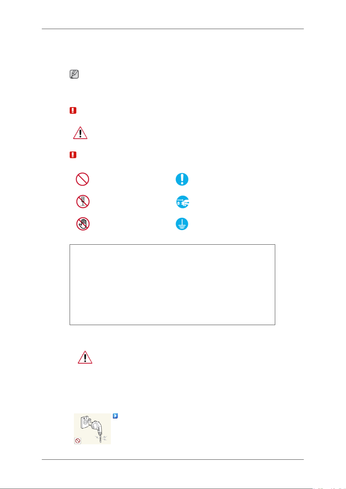
Do not use a damaged power cord or plug or a damaged or loose power
outlet.
• Otherwise, this may result in electric shock or fire.
Safety Instructions
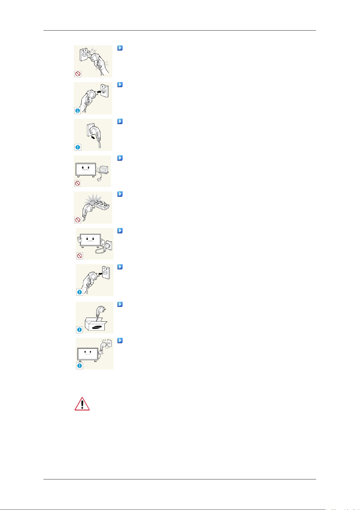
Do not touch the power plug with wet hands when removing or plug-
ging the plug into the outlet.
• Otherwise, this may result in electric shock.
Make sure to connect the power cord to a grounded power outlet.
• Otherwise, it may result in electric shock or personal injury.
Ensure that the power plug is plugged into the power outlet firmly and
correctly.
• Otherwise, this may result in fire.
Do not forcefully bend or pull the power plug and do not place any
heavy material on it.
• Otherwise, this may result in fire.
Do not connect multiple appliances to the same power outlet.
• Otherwise, this may cause fire due to overheating.
Do not disconnect the power cord while using the product.
• Otherwise, this may result in damage to the product due to electric
shock.
To disconnect the apparatus from the mains, the plug must be pulled
out from the mains socket, therefore the mains plug shall be readily operable.
• Otherwise, this may cause electric shock or fire.
Use only the power cord provided by our company. Do not use the
provided power cord of another product.
• Otherwise, this may result in fire or electric shock.
Connect the power plug to a wall outlet that can be easily reached.
• When a problem occurs with the product, you must unplug the power
plug to cut the power off completely. You cannot cut the power off
completely using only the power button on the product.
Installation
Be sure to contact an authorized Service Center when installing your monitor in
a location with heavy dust, high or low temperatures, high humidity, and exposed
to chemical substances and where it operates for 24 hours such as at airports,
train stations etc.
Failure to do so may cause serious damage to your monitor.
Safety Instructions
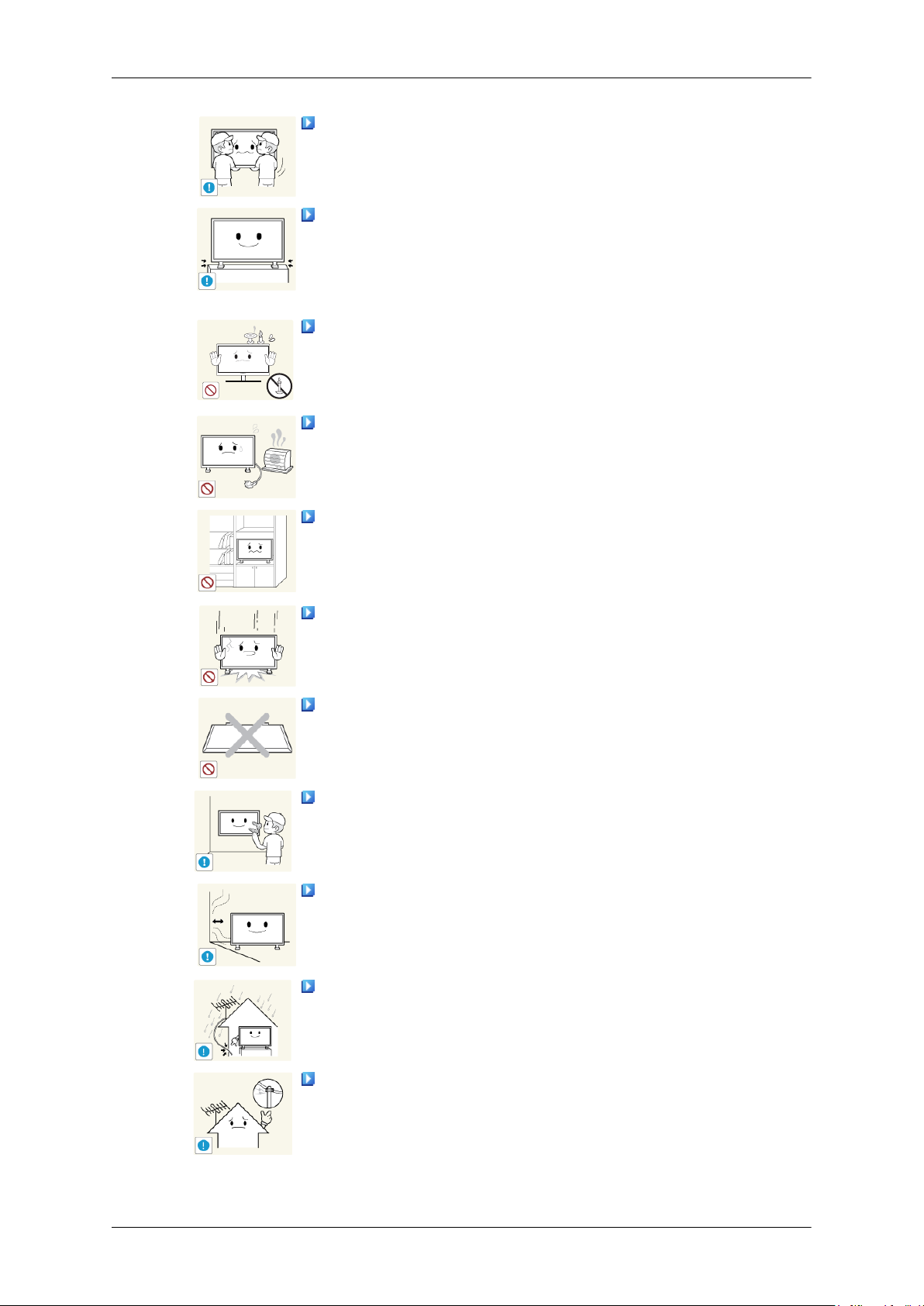
Ensure that at least two persons lift and move the product.
• Otherwise, it
age the product.
When installing the product in a cabinet or rack, make sure that the
front end of the bottom of the product does not project out.
• Otherwise, it may fall or cause personal injury.
Use a cabinet or rack of a size appropriate to the product.
•
DO NOT PLACE CANDLES, MOSQUITO REPELLANT, CIGARETTES AND
UCT.
• Otherwise, this may result in fire.
Keep heating appliances as far away from the power cord or the product as possible.
• Otherwise, this may result in electric shock or fire.
Do not install it in a badly ventilated location such as a bookcase or
closet.
• Otherwise, this
temperature.
When putting the product down, make sure to put it down softly.
may be dropped and cause personal injury, and/or dam-
ANY HEATING APPLIANCES NEAR THE PROD-
may result in fire due to an increase in the internal
• Otherwise, this may result in damage to the screen display.
Do not place the front of the product on the floor.
• Otherwise, this may result in damage to the screen display.
Ensure that an authorized installation company installs the wall mount.
• Otherwise, it may fall and cause personal injury.
• Make sure to install the specified wall mount.
Install your product in a well ventilated location. Ensure that there is
a clearance of more than 4 inches (10 cm) from the wall.
• Otherwise, it may result in fire due to an increase in the internal tem-
perature.
Bend the outdoor antenna cable downwards at the location where it
goes in so that rainwater does not flow in.
• If rainwater enters the product, it may result in electric shock or fire.
Install the antenna far away from any high voltage cables.
• If the
antenna touches or falls onto a high voltage cable, it may result
in electric shock or fire.
Clean
Safety Instructions
Ensure that the packaging vinyl is kept away from children.
• Otherwise, it may result in serious harm (suffocation) if children play
with it.
If the height of your monitor is adjustable, do not place any object or
part of your body on the stand when lowering it.
• This may cause damage to the product or the person carrying it.
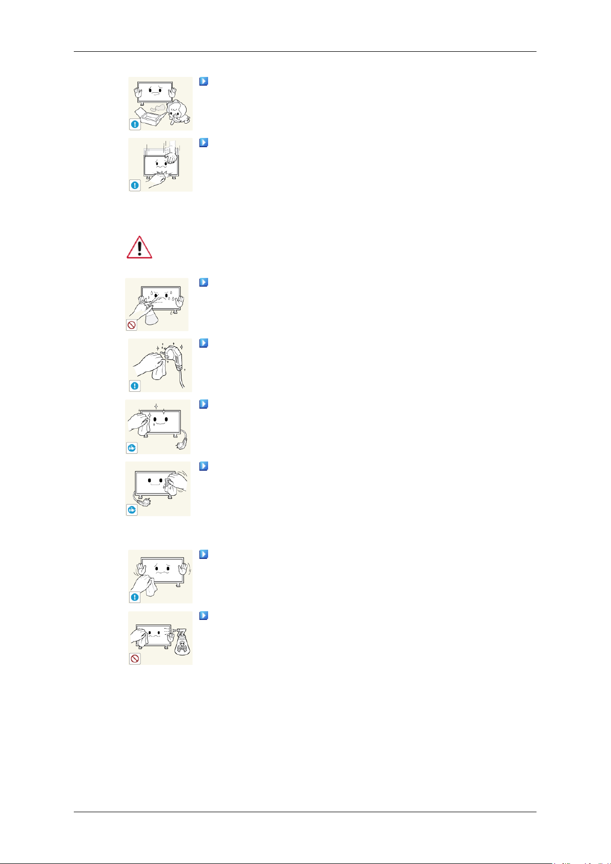
When cleaning the monitor case or the surface of the TFT-LCD screen, wipe
with a slightly moistened, soft cloth.
Do not spray cleaner directly onto the surface of the product.
• Otherwise, this may result in the discoloration and distortion of the
structure and the screen surface may peel off.
When cleaning the power plug pins or dusting the power outlet, clean
it with a dry cloth.
• Otherwise, it may result in fire.
When cleaning the product, make sure to disconnect the power cord.
• Otherwise, it may result in electric shock or fire.
When cleaning the product, disconnect the power cord and clean it
with a soft, dry cloth.
• (Do not use chemicals such as wax, benzene, alcohol, thinner, mos-
quito repellant, lubricant, or cleaner.) These may change the appearance of the product surface and peel off the indication labels on the
product.
Since the product housing is easily scratched, make sure to use the
specified cloth only.
When cleaning the product, do not spray water directly onto the main
body of the product.
• Ensure that water does not enter the product and that it is not wet.
• Otherwise, this may result in electric shock, fire or a malfunction.
Others
Safety Instructions
The product is a high voltage product. Do not disassemble, repair or
modify the product yourself.
• Otherwise, this may result in electric shock or fire. If the product
needs to be repaired, contact a Service Center.
If there is a strange smell or a strange sound or smoke is coming from
the product, disconnect the power plug immediately and contact a Service
Center.
• Otherwise, this may result in electric shock or fire.
Do not place this product in a location exposed to moisture, dust,
smoke, water, or in a car.
• Otherwise, this may result in electric shock or fire.
When you drop the product or the case is broken, turn the power off
and disconnect the power cord. Contact a Service Center.
• Otherwise, this may result in electric shock or fire.
If thunder or lightning is occurring, do not touch the power cord or
antenna cable.
• Otherwise, this may result in electric shock or fire.
Do not try to move the monitor by pulling only the wire or the signal
cable.
• Otherwise, it may fall and result in electric shock, damage to the
product or fire due to damage to the cable.
Do not lift or move the product back and forwards or right and left
while only holding the power cord or signal cables.
• Otherwise, it may fall and result in electric shock, damage to the
product or fire due to damage to the cable.
Make sure that the ventilating opening is not blocked by a table or
curtain.
• Otherwise, it may result in fire due to an increase in the internal tem-
perature.
Do not place any containers containing water, vases, flowerpots, medicines as well as any metal on the product.
• If water or a foreign material enters the product, disconnect the power
cord and contact a Service Center.
• This may result in a product malfunction, electric shock, or fire.
Do not use or keep combustible spray or flammable material near the
product.
• Otherwise, this may result in an explosion or fire.

Safety Instructions
Do not insert any metal, such as chopsticks, coins, pins and steel, or
flammable objects, such as matches or paper, inside the product (through
the ventilating openings, input and output terminals, etc).
• If water or foreign material enters the product, disconnect the power
cord and contact a Service Center.
• Otherwise, this may result in electric shock or fire.
When using a fixed screen for a long time, an afterimage or stain may
occur.
• If you are not using your product for a long period of time, put it into
sleep mode or use a moving screen saver.
Set a resolution and frequency appropriate to the product.
• Otherwise, your eyesight may be damaged.
When using headphones or earphones, do not turn the volume too high.
• Having the sound too loud may damage your hearing.
To avoid eyestrain, do not sit too close to the product.
Take a rest for at least five (5) minutes after using the monitor for one
(1) hour.
This reduces eye fatigue.
Do not install it in an unstable location such as an unstable rack or
uneven surface or a location exposed to vibrations.
• Otherwise, it may fall and cause personal injury and/or damage the
product.
• If you use the product in a location exposed to vibrations, it may
damage the product and result in fire.
When moving the product, turn the power off and disconnect the power
plug, antenna cable, and all the cables connected to the product.
• Otherwise, it may result in electric shock or fire.
Ensure that children do not hang onto the product or climb up onto the
product.
• The product may fall and cause personal injury or death.
If you do not use the product for a long period of time, disconnect the
power cord from the power outlet.
• Otherwise, this may result in overheating or fire due to dust, and may
result in fire due to electric shock or leakage.

Safety Instructions
Do not place any heavy items or toys or confectionery, such as cookies
etc. that may attract the attention of children and to the product.
• Your children may hang onto the product causing it to fall and this
may result in personal injury or death.
Be careful that children do not place the battery in their mouths when
removed from the remote control. Place the battery in a location that
children or infants cannot reach.
• If children have had the battery in their mouths, consult your doctor
immediately.
When replacing the battery, insert it with the right polarity (+, -).
• Otherwise, the battery may become damaged or it may cause fire,
personal injury or damage due to leakage of the internal liquid.
Use only the specified standardized batteries, and do not use a new
battery and a used battery at the same time.
• Otherwise, the batteries may be damaged or cause fire, personal in-
jury or damage due to a leakage of the internal liquid.
The batteries (and rechargeable batteries) are not ordinary refuse and
must be returned for recycling purposes. The customer is responsible for
returning the used or rechargeable batteries for recycling.
• The customer can return used or rechargeable batteries to a nearby
public recycling center or to a store selling the same type of the battery
or rechargeable battery.
Do not place the product in a location exposed to direct sunlight or
near any heat such as a fire or heater.
• This may reduce the lifetime of the product, and may result in fire.
Do not drop any objects onto the product or cause any impact to the
product.
• Otherwise, this may result in electric shock or fire.
Do not use a humidifier near the product.
• Otherwise, this may result in electric shock or fire.
When there is a gas leak, do not touch the product or the power plug;
ventilate immediately.
• If a spark occurs, it may cause an explosion or fire.
If the product has been turned on for a long time, the display panel
becomes hot. Do not touch it.

Safety Instructions
Keep the small accessories in a location out of the reach of children.
Be careful when adjusting the angle of the product or the height of the
stand.
• This may result in personal injury as your hand or fingers may be-
come caught.
• Also, if you tilt the product too far, it may fall and cause personal
injury.
Do not install the product in a location low enough for children to
reach.
• Otherwise, it may fall and result in personal injury.
• Since the front part of the product is heavy, install the product on a
level and stable surface.
Do not put any heavy objects on the product.
• This may result in personal injury and/or damage to the product.

Introduction
Package Contents
Checking the Contents of the Package
Remove the lock from the package box, as shown in the figure above.
holding the grooves on both
• After unpacking the package, make sure to check the contents of the package.
• Store the packaging box in case you need to move the Product later.
• If any items are missing, contact your dealer.
• Contact a local dealer to purchase optional items.
Unpacking
Lift up the package box by
sides of the package box.
Note
Check the contents of the
package.
Remove the Styrofoam and
vinyl cover.
LCD Display
Manuals
Introduction
Quick Setup Guide Warranty Card
(Not available in all loca-
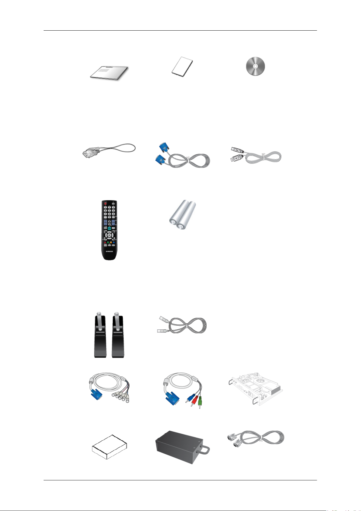
Cables
Power Cord D-Sub Cable USB Cable
Others
Remote Control
Batteries (AAA X 2)
User Manual
tions)
(BP59-00138B)
Sold separately
Semi Stand KIT LAN Cable
RGB to BNC Cable RGB to COMPONENT Ca-
(Not available in all loca-
tions)
ble
Network Box

Sold separately
Wall Mount KIT TV Tuner box
Note
• Accessories that can be purchased with the product vary by country.
Your LCD Display
The color and the appearance may differ depending on the product, and the specifications are subject
to change without prior notice to improve the performance.
Front
Introduction
RS232C Cable
(US Only)
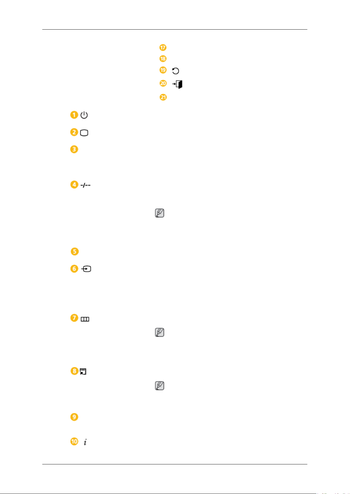
MENU button [MENU]
Opens the on-screen menu and exits from the menu. Also use to exit the OSD menu
or return to the previous menu.
Navigate buttons (Up-Down buttons)
Moves from one menu item to another vertically or adjusts selected menu values.
Adjust buttons (Left-Right buttons) / Volume buttons
Moves from one menu item to another horizontally or adjusts selected menu values. When OSD is not on the screen, press the button to adjust volume.
ENTER button [ENTER]
Activates a highlighted menu item.
SOURCE button [SOURCE]
Switches from PC mode to Video mode. Selects the input source that an external
device is connected to.
[PC] → [DVI] → [AV] → [Component] → [HDMI1] → [HDMI2] → [Dis-
playPort] → [MagicInfo] → [TV]
Note
• The [RGB/COMPONENT IN] port is compatible with RGB (PC) and Component signals.
Introduction
However, the picture may display abnormally if the connected external input
signal is different from the selected video signal.
• MagicInfo can only be enabled when a network box is connected.
• A TV tuner box (sold separately) must be connected to use the TV. (US Only)
D.MENU button
Opens the on-screen D.MENU.
Note
The D.MENU button is activated when a TV tuner is connected and otherwise, the
PIP button is enabled.
PIP button
Push the PIP button to turn the PIP screen On / Off.
Power button [ ]
Use this button for turning the LCD Display on and off.
Brightness Sensor
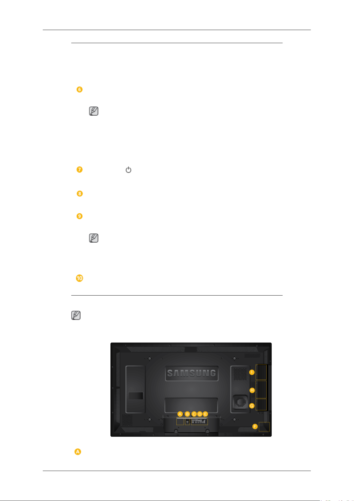
Rear
Automatically detects the surrounding brightness.
Power indicator
Shows PowerSaver mode by blinking green
Note
See PowerSaver described in the manual for further information regarding power
saving functions. For energy conservation, turn your LCD Display OFF when it
is not needed or when leaving it unattended for long periods.
Remote Control Sensor
Aim the remote control towards this spot on the LCD Display.
Note
See the "Connections" section for details about cable connections. The LCD Display's configuration
at the back may vary slightly depending on the model.
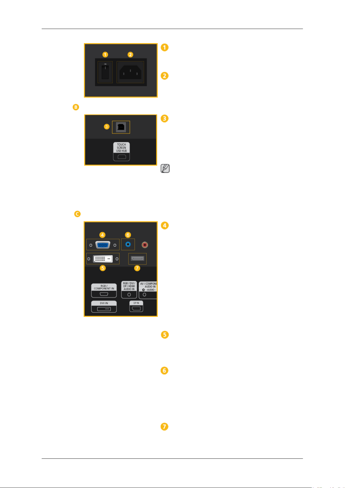
Introduction
POWER S/W ON [ I ] / OFF
Switches the LCD Display On/Off.
POWER
The power cord plugs into the LCD Display and
the wall outlet.
TOUCH SCREEN USB HUB
Connects to a network box (sold separately) or PC
in order to use the touchscreen.
To use the touchscreen, install the touchscreen
driver.
Note
You can use basic touch-screen functions without
installing the program. However, to have full access to additional functions, you must install the
program provided.
RGB/COMPONENT IN (PC/COMPONENT
Connection Terminal (Input))
• Connect the [RGB/COMPONENT IN] port
on the monitor to the RGB port on the PC using the D-SUB cable.
• Connect the [RGB/COMPONENT IN] port
on the monitor to the COMPONENT port on
the external device using the RGB to COMPONENT cable.
• Connect the [RGB/COMPONENT IN] port
on the monitor to the BNC port on the PC using the RGB to BNC cable.
DVI IN (PC Video Connection Terminal)
Connect the [DVI IN] port on the monitor to the
DVI port on the PC using the DVI cable.
RGB/DVI/DP/HDMI AUDIO IN (PC/DVI/
DP/HDMI Audio Connection Terminal (Input))
Connect the [RGB/DVI/DP/HDMI AUDIO IN]
terminal of the monitor and the speaker output
terminal of your computer's so und card using a
stereo cable (sold separately).
DP IN
Receives a signal from the Display port.

Introduction
Connect a DP cable to [DP IN] on the product and
DP IN on another display.
AV/COMPONENT AUDIO IN [R-AUDIO-L]
Connect the [AV/COMPONENT AUDIO IN [R-
AUDIO-L]] port on the monitor to the audio
output port on the PC or on the external device
using an audio cable.
AV IN
Connect the [AV IN] terminal of your monitor to
the video output terminal of the external device
using a VIDEO cable.
AUDIO OUT
Connect a headphone or an External speaker.
DC OUT
Make sure to use connecting [DC OUT] terminal
to the authorized TV-Tuner Box(US Only).
Otherwise, this may result in damage to
the product.
HDMI IN 1
• Connect the [HDMI IN 1] terminal at the back
of your LCD Display to the HDMI terminal
of your digital output device using a HDMI
cable.
• Up to HDMI 1.3 can be supported.
Note
• A normal external device (DVD player or
camcorder, etc.) or a TV tuner box can be
connected to the [HDMI IN 1] terminal.
• To use a TV tuner box(US Only), make sure
to connect it to the [HDMI IN 1] terminal.
HDMI IN 2 (MAGICINFO)
• Connect the [HDMI IN 2 (MAGICINFO)]
terminal at the back of your LCD Display to
the HDMI terminal of your digital output device using a HDMI cable.
• Up to HDMI 1.3 can be supported.

Introduction
Note
To use MagicInfo, the network box specified
separately by Samsung must be installed inside
the product and the MagicInfo output of the network box must be connected to the [HDMI IN 2
(MAGICINFO)] terminal.
For more information on how to purchase and install a network box, contact Samsung Electronics.
RJ 45 MDC (MDC PORT)
MDC(Multiple Display Control) Program Port
Connect the LAN cable to [RJ45 MDC] on the
product and LAN on the PC. To use an MDC, the
MDC Program must be installed on the PC.
Note
Go to Multi Control and select RJ45 MDC as
the MDC Connection.
RS232C OUT/IN (RS232C Serial PORT)
MDC(Multiple Display Control) Program Port
Connect a serial cable (cross type) to [RS232C]
on the product and RS232C on the PC. To use an
MDC, the MDC Program must be installed on the
PC.
Note
Go to Multi Control and select RS232C MDC
as the MDC Connection.
Kensington Lock slot
A Kensington Lock is an anti-theft device that
enables users to lock the product so that they can
safely use it in public locations. Since the shape
and usage of the locking device may differ depending on the model and the manufacturer, for
more information, refer to the User Manual supplied with the locking device for more information.
Note
You must purchase the Kensington Lock separately.

Introduction
To lock the product, follow these steps:
1. Wrap the Kensington lock cable around a
large, stationary object such as a desk or
chair.
2. Slide the end of the cable with the lock at-
tached through the looped end of the Kensington lock cable.
3. Insert the Kensington Lock into the security
slot (
4.
Lock the lock ( ).
Note
• These are general instructions. For exact instructions, see the User Manual supplied with
the locking device.
• You can purchase the locking device from an
electronics store, an online shop, or our service Center.
Connecting a Network Box (sold separately)
RGB OUT
MagicInfo video output port
MAGICINFO OUT
It can be used by connecting it to the [HDMI IN
2 (MAGICINFO)] terminal using a DP to HDMI
cable.
) on the back of the display.
LAN (LAN Connection Terminal)
Connects to a LAN cable to allow Internet or network access in MagicInfo mode.
Connecting a Network Box (sold separately)
USB (USB Connection Terminal)
Keyboard / Mouse, Mass Storage Device Compatible.
AUDIO OUT
Connect a headphone or an External speaker.
RS232C (RS232C Serial PORT)
Serial port
Connecting a Network Box (sold separately)

Introduction
POWER
Connect the [POWER] terminal of the product
and the [POWER] terminal of the monitor using
a power extension cable.
POWER
Connects to a mains socket via the power cord.
POWER S/W ON [ I ] / OFF
Turns the network box on or off.
Note
• See the "Connections" section for details about cable connections.
• The power switches of both of the monitor and the network box must be turned on for the network
box to operate normally.
Remote Control
Note
The performance of the remote control may be affected by a TV or other electronic device operating
near the LCD Display, causing a malfunction due to interference with the frequency.
A TV tuner box (sold separately) must be connected to use the TV. (US Only)
POWER
OFF
Number Buttons
/ GUIDE button
+ VOL -
SOURCE
D.MENU
TOOLS
Up-Down Left-Right buttons
INFO
The Color button and the PC/DVI/HDMI/DP
selection button.
TTX/MIX
MTS/DUAL
ENTER/PRE-CH
MUTE
CH/P
Introduction
TV
MENU
RETURN
EXIT
MagicInfo
POWER
OFF
Number Buttons
/ GUIDE button
+ VOL -
SOURCE
Turns the product On.
Turns the product Off.
Used to enter the password during the OSD adjustment or to use
MagicInfo.
Press to change the channel.
The "-" button is used to select Digital channels.
Electronic Program Guide (EPG) display.
Note
This button can only be used in TV mode while a TV tuner box
(sold separately) is connected.
Adjusts the audio volume.
Selects a connected external input source or MagicInfo mode.
Press the button to change the input signal SOURCE.
D.MENU
TOOLS
Up-Down Left-Right but-
tons
INFO
Changing the SOURCE is only allowed for external devices that
are connected to the LCD Display at the time.
DTV menu display
Note
This button can only be used in TV mode while a TV tuner box
(sold separately) is connected.
Use to quickly select frequently used functions.
Note
This function does not work for this LCD Display.
Moves from one menu item to another horizontally, vertically or
adjusts selected menu values.
Current picture information is displayed on the upper left corner
of the screen.
Introduction
The Color button and the
PC/DVI/HDMI/DP selection
button.
TTX/MIX
MTS/DUAL
In TV mode, these buttons can be used to configure a list of channels.
You can select the PC, DVI, HDMI or DP(DisplayPort) external
input directly in a mode other than TV mode.
TV channels provide written information services via teletext.
- Teletext Buttons
Note
This function does not work for this LCD Display.
MTS-
You can select MTS (Multichannel Television Stereo) mode.
Audio Type MTS/S_Mode Default
FM Stereo Mono Mono Manual Change
Stereo
SAP
Mono �Í Stereo
Mono �Í SAP
Mono
ENTER/PRE-CH
MUTE
CH/P
DUAL-
STEREO/MONO, DUAL l / DUAL ll and MONO/NICAM
MONO/NICAM STEREO can be operated depending on the
broadcasting type by using the DUAL button on the remote control
while watching TV.
Note
Enabled when a TV tuner box is connected.
This button is used to return to the immediately previous channel.
Note
Enabled when a TV tuner box is connected.
Pauses (mutes) the audio output temporarily. This is displayed on
the lower left corner of the screen. The audio comes back on if
MUTE or - VOL + is pressed in the Mute mode.
In TV mode, selects TV channels.
Note
TV
Enabled when a TV tuner box is connected.
Allows you to watch an analogue or digital TV.
Note
Enabled when a TV tuner box is connected.

Introduction
MENU
RETURN
EXIT
MagicInfo
User Installation Guide
Note
• Be sure to call an installation expert of Samsung Electronics to install the product.
• The warranty becomes invalid if the product is installed by someone other than a professional
authorized by Samsung Electronics.
• A Samsung Electronics service center can provide details.
Opens the on-screen menu and exits from the menu or closes the
adjustment menu.
Returns to the previous menu.
Exits from the menu screen.
MagicInfo Quick Launch Button.
Note
Enabled when a Network box is connected.
Tilt Angle and Rotation
1 2
1. The product can be tilted up to 15 degrees from a vertical wall.
2. To use the product in portrait mode, rotate it clockwise so that the LED indicator is at the bottom.
Ventilation requirement
1. Vertical wall mount condition
<Side view>

Introduction
A : min. 40 mm
B: Ambient temperature Measuring point < 35°C
• When installing the product onto a vertical wall, be sure there is a 40 mm space or more behind
the product for ventilation, as shown above, and maintain the ambient temperature at 35×C or
lower.
Note
A Samsung Electronics service center can provide details.
2. Embedded Mount guide
<Side view> <Top view>
A : min. 40 mm
B : min. 70 mm
C : min. 50 mm
D : min. 50 mm
E : Ambient temperature Measuring point < 35°C
• When embedding the product in a wall, be sure there is some space behind the product for venti-
lation, as shown above, and maintain the ambient temperature at 35°C or lower.
Note
A Samsung Electronics service center can provide details.

3. Floor mount guide
<Side view>
A : min. 50 mm
B: Ambient temperature Measuring point < 20°C
• When embedding the product in the floor, be sure there is a 50 mm space or more behind the product
for ventilation, as shown above, and maintain the ambient temperature at 20×C or lower.
Note
A Samsung Electronics service center can provide details.
Introduction
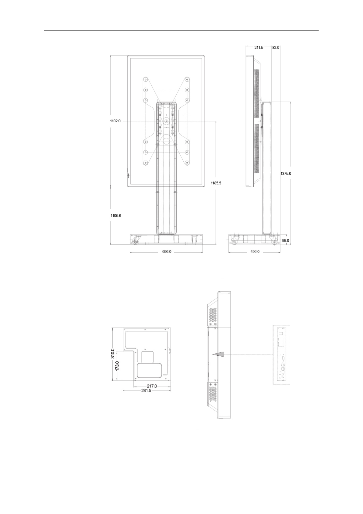
Mechanical Layout
(400TS-3)

(460TS-3)
Introduction
Installation VESA Bracket
• When installing VESA, make sure to comply with the international VESA standards.
• Purchasing VESA Bracket and Installation Information : Please contact your nearest SAMSUNG
Distributor to place an order. After your order is placed, installation professionals will visit you
and install the bracket.
• At least 2 persons are needed in order to move the LCD Display.
• SAMSUNG is not responsible for any product damage or any injury caused by installation at
customer's discretion.
Dimensions
(400TS-3)
(460TS-3)

Notice
For securing the bracket on a wall, use only machine screws of 6 mm diameter and 8 to 12 mm length.
Accessories (sold separately)
• Dimension with welcome board
(400TS-3)
Introduction
(460TS-3)
Introduction
• Dimension with other accessories
Wall Bracket Installation
• Contact a technician for installing the wall bracket.
• SAMSUNG Electronics is not responsible for any damages to the product or harm to customers
when the installation is done by the customer.
• This product is for installing on cement walls. The product may not stay in place when installed
on plaster or wood.
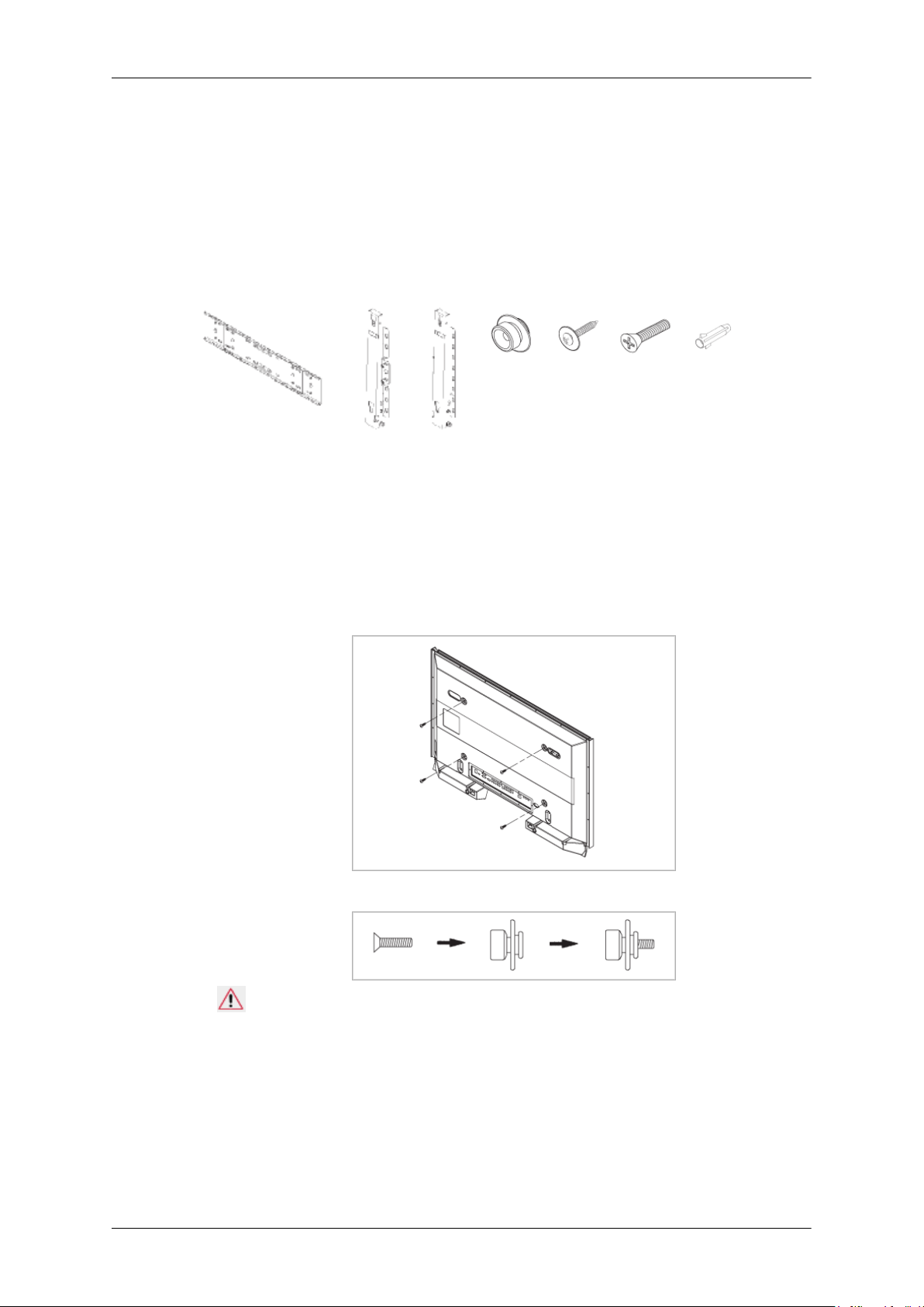
Components
Only use the components and accessories shipped with the product.
Introduction
Wall Bracket(1) Hinge(Left 1, Right1)Plastic
To mount the product on the wall bracket
The shape of the product may vary depending on the model. (The assemblies of the plastic hanger and
the screw are the same)
1. Remove the 4 screws on the back of the product.
2. Insert the screw B into the plastic hanger.
Hanger
(4)
Screw
(A)(11)
Screw(B)
(4)
Anchor
(11)
Notice
• Mount the product on the wall bracket and make sure it is properly fixed to the left and right
plastic hangers.
• Be careful when installing the product on the bracket as fingers can be caught in the holes.
• Make sure the wall bracket is securely fixed to the wall, or the product may not stay in place
after installation.
3. Tighten the 4 screws in step 2 (plastic hanger + screw B)to the rear holes of the product.

Introduction
4. Remove safety pin (3) and insert the 4 product holders into the corresponding bracket holes (1).
Then place the product(2) so that it is firmly fixed to the bracket. Make sure to re-insert and tighten
the safety pin (3) to securely hold the product to the bracket.
A - LCD Display
B - Wall Bracket
C - Wall
Wall Bracket Angle Adjustment
Adjust the bracket angle to -2× before installing it on the wall.
1. Fix the product to the wall bracket.
2. Hold the product at the top in the center and pull it forward (direction of the arrow) to adjust the
angle.
Note
You can adjust the bracket angle between -2× and 15×.
Make sure to use the top center, and not the left or the right side of the product to adjust the angle.
Remote Control (RS232C)
Cable connections
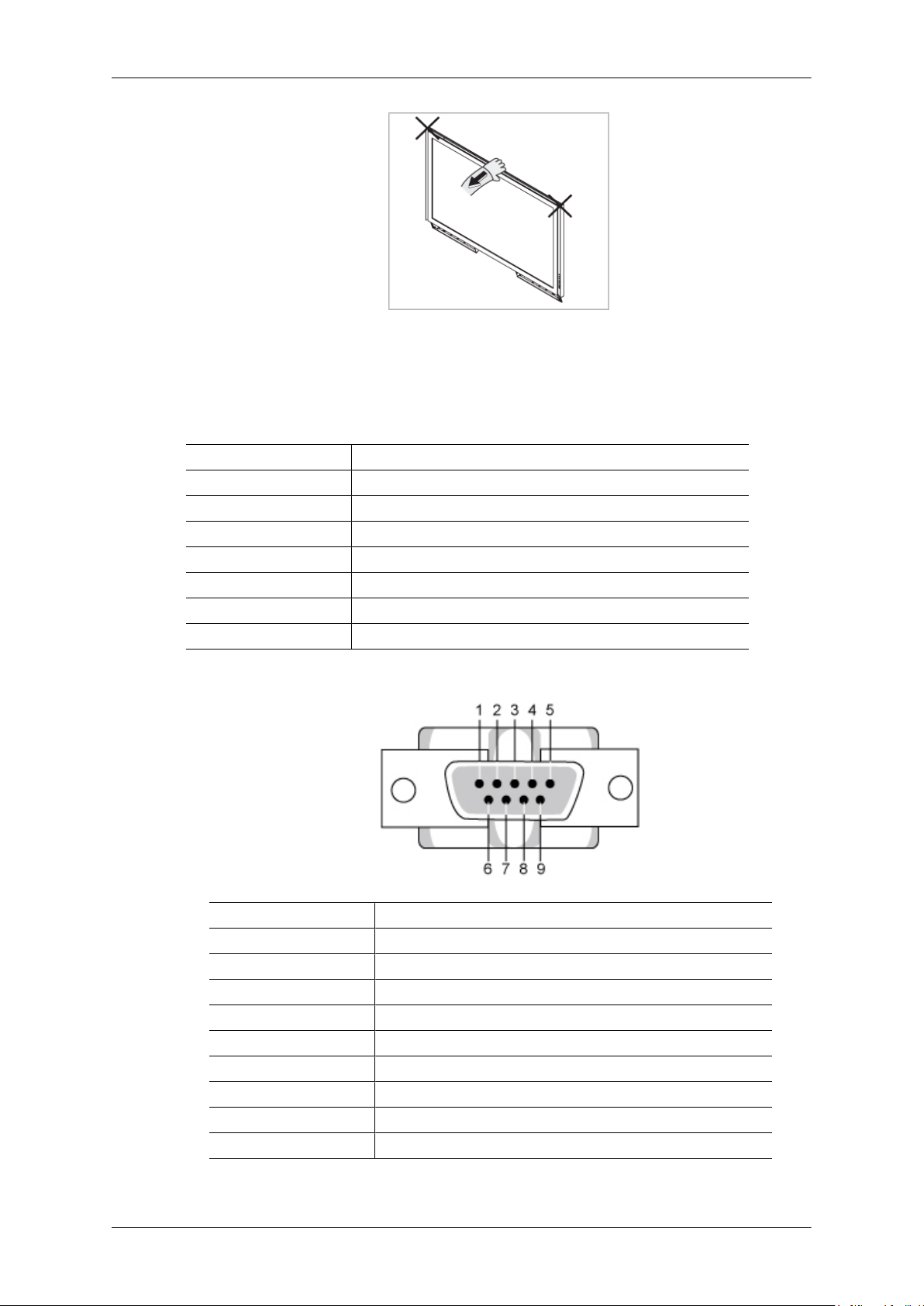
interface RS232C(9 pin)
pin TxD(No.2) RxD(No.3) GND(No.5)
Bits rate 9600 bps
Data Bits 8 bit
Parity None
Stop Bits 1 bit
Flow control None
Maximum length 15 m (only shielded type)
Introduction
• Pin assignment
Pin Signal
1 Data Carrier Detect
2 Received Data
3 Transmitted Data
4 Data Terminal Ready
5 Signal Ground
6 Data Set Ready
7 Request to Send
8 Clear to Send
9 Ring Indicator
• RS232C cable

Introduction
Connector : 9-pin D-Sub
Cable : Cross (reversed) cable
-P1- -P1- -P2- -P2-
FEMALE Rx
2
--------->
3
Rx
FEMALE
• Connecting method
Tx
Gnd
3
5
<---------
----------
2
5
Tx
Gnd
Control codes
• Get control
• Set control
• commanding words
No. command type command Value range
1 Power control 0x11 0~1
Header command
ID
0xAA command type 0
Header command
ID
0xAA command
type
DATA Length
DATA
Length
1 Value
CheckSum
DATA
CheckSum

Introduction
2 Volume control 0x12 0~100
3 Input source control 0x14 4 Screen Mode control 0x18 5 Screen Size control 0x19 0~255
6 PIP on/off control 0x3C 0~1
7 Auto adjustment control 0x3D 0
8 Video wall Mode control 0x5C 0~1
9 Safety Lock 0x5D 0~1
- ID should show hexadecimal value of assigned ID, but ID 0 should be 0xFF.
- Every communication will be made in hexadecimals and Checksum is the sum of all remainings.
If it exceeds two digits,for example, it is 11+FF+01+01=112, discard the number in the first digit
like below.
example)PowerOn&ID=0
Header command
ID
0xAA 0x11 1 Power
Header command
ID
0xAA 0x11 1 1
If you want to control every mechanism connected with Serial Cable regardless of its ID, set ID
part to "0xFE" and send commands. At the time, each product will follow commands but it will
not respond with ACK.
• Power Control
• Function
Personal Computer turns TV / Monitor power ON/OFF.
• Get Power ON/OFF Status
Header command
0xAA 0x11 0
DATA
Length
DATA
Length
ID
DATA 1
CheckSum
DATA 1
12
DATA Length
CheckSum
• Set Power ON/OFF
Header command
ID
0xAA 0x11 1 Power
Power : Power code to be set on TV / Monitor
1 : Power ON
0 : Power OFF
DATA
Length
DATA
CheckSum

• Ack
Introduction
Header command
0xAA 0xFF 3 ‘A’ 0x11 Power
Power : Same as above
• Nak
Header command
0xAA 0xFF 3 ‘N’ 0x11 ERR
ERR : Error code that shows what occurred error is
• Volume Control
• Function
Personal Computer changes volume of TV / Monitor.
• Get Volume Status
ID
ID
DATA
Length
DATA
Length
Ack/Nak r-CMD Val1
Ack/Nak r-CMD Val1
Check
Sum
Check
Sum
Header command
0xAA 0x12 0
• Set Volume
Header command
ID
0xAA 0x12 1 Volume
Volume : Volume value code to be set on TV / Monitor (0 ~ 100)
• Ack
Header command
ID
0xAA 0xFF 3 ‘A’ 0x12 Volume
Volume : Same as above
• Nak
DATA
Length
ID
Ack/Nak r-CMD Val1
DATA Length
DATA
Length
CheckSum
DATA
CheckSum
Check
Sum
Header command
ID
0xAA 0xFF 3 ‘N’ 0x12 ERR
ERR : Error code that shows what occurred error is
DATA
Length
Ack/Nak r-CMD Val1
Check
Sum

• Input Source Control
• Function
Personal Computer changes input source of TV / Monitor.
• Get Input Source Status
Introduction
Header command
0xAA 0x14 0
• Set Input Source
Header command
ID
0xAA 0x14 1 Input Source
Input Source : Input Source code to be set on TV / Monitor
0x14 PC
0x1E BNC
0x18 DVI
0x0C AV
0x04 S-Video
0x08 Component
0x20 MagicInfo
0x1F DVI_VIDEO
0x30 RF(TV)
0x40 DTV
0x21 HDMI1
0x22 HDMI1_PC
0x23 HDMI2
0x24 HDMI2_PC
0x25 DisplayPort
ID
DATA
Length
DATA Length
CheckSum
DATA
CheckSum
Caution
DVI_VIDEO, HDMI1_PC, HDMI2_PC → Get Only
In the case of MagicInfo, only possible with models include MagicInfo
In the case of TV, only possible with models include TV.
• Ack
Header command
ID
DATA
Length
Ack/Nak r-CMD Val1
Check
Sum

Introduction
0xAA 0xFF 3 ‘A’ 0x14
Input Source : Same as above
• Nak
Header command
0xAA 0xFF 3 ‘N’ 0x14 ERR
ERR : Error code that shows what occurred error is
• Screen Mode Control
• Function
Personal Computer changes "Screen Mode" of TV/Monitor.
Cannot be controlled when Video Wall is on.
Caution
ID
DATA
Length
Input
Source
Ack/Nak r-CMD Val1
Check
Sum
Only works with models include TV.
• Get Screen Mode Status
Header command
0xAA 0x18 0
• Set Picture Size
Header command
ID
0xAA 0x18 1 Screen Mode
Screen Mode : Screen Mode code to be set on TV / Monitor
0x01 16 : 9
0x04 Zoom
0x31 Wide Zoom
0x0B 4 : 3
ID
DATA
Length
DATA Length
CheckSum
DATA
CheckSum
• Ack
Header command
ID
0xAA 0xFF 3 ‘A’ 0x18
Screen Mode : Same as above
DATA
Length
Ack/Nak r-CMD Val1
Screen
Mode
Check
Sum

• Nak
Introduction
Header command
0xAA 0xFF 3 ‘N’ 0x18 ERR
ERR : Error code that shows what occurred error is
• Screen Size Control
• Function
Personal Computer recognizes the screen size of TV / Monitor.
• Get Screen Size Status
Header command
0xAA 0x19 0
• Ack
Header command
0xAA 0xFF 3 ‘A’ 0x19
ID
ID
DATA
Length
DATA
Length
Ack/Nak r-CMD Val1
DATA Length
ID
Ack/Nak r-CMD Val1
Screen
Size
Check
Sum
CheckSum
Check
Sum
Screen Size : Screen Size of TV / Monitor (Range : 0 ~ 255, Unit : Inch)
• Nak
Header command
0xAA 0xFF 3 ‘N’ 0x19 ERR
ERR : Error code that shows what occurred error is
• PIP ON / OFF Control
• Function
The PC turns the PIP function of a TV or Monitor ON / OFF.
This does not operate in MagicInfo mode.
• Get the PIP ON / OFF Status
Header command
0xAA 0x3C 0
ID
DATA
Length
Ack/Nak r-CMD Val1
DATA Length
ID
Check
Sum
CheckSum

• Set the PIP ON / OFF
Introduction
Header command
ID
0xAA 0x3C 1 PIP
PIP : The PIP ON / OFF code to set for the TV or Monitor
1 : PIP ON
0 : PIP OFF
• Ack
Header command
ID
0xAA 0xFF 3 ‘A’ 0x3C PIP
PIP : Same as above
• Nak
Header command
ID
0xAA 0xFF 3 ‘N’ 0x3C ERR
DATA
Length
DATA
Length
DATA
Length
Ack/Nak r-CMD Val1
Ack/Nak r-CMD Val1
DATA
CheckSum
Check
Sum
Check
Sum
ERR : Error code that shows what occurred error is
• Auto Adjustment Control (PC, BNC Only)
• Function
Personal Computer controls PC system screen automatically.
• Get Auto Adjustment Status
None
• Set Auto Adjustment
Header command
ID
0xAA 0x3D 1 Auto Adjust-
Auto Adjustment : 0x00 (Always)
DATA
Length
DATA
CheckSum
ment
• Ack
Header command
ID
DATA
Length
Ack/Nak r-CMD Val1
Check
Sum

Introduction
0xAA 0xFF 3 ‘A’ 0x3D
• Nak
Header command
0xAA 0xFF 3 ‘N’ 0x3D ERR
ERR : Error code that shows what occurred error is
• Video Wall Mode Control
• Function
Personal Computer converts Video Wall Mode of TV / Monitor when Video Wall is ON.
Only works with TV / Monitor where Video Wall is on.
Does not operate in MagicInfo
ID
DATA
Length
Auto Ad-
justment
Ack/Nak r-CMD Val1
Check
Sum
• Get Video Wall Mode
Header command
0xAA 0x5C 0
• Set Video Wall Mode
Header command
0xAA 0x5C 1 Video Wall
Video Wall Mode : Video Wall Mode code to be set on TV / Monitor
1 : Full
0 : Natural
• Ack
Header command
ID
0xAA 0xFF 3 ‘A’ 0x5C
ID
DATA
Length
ID
Ack/Nak r-CMD Val1
DATA Length
DATA
Length
DATA
Mode
Video
Wall
Mode
CheckSum
CheckSum
Check
Sum
Video Wall Mode : same as above
• Nak

Introduction
Header command
0xAA 0xFF 3 ‘N’ 0x5C ERR
ERR : Error code that shows what occurred error is
• Safety Lock
• Function
Personal Computer turns Safety Lock function of TV / Monitor ON / OFF.
Can operate regardless of whether power is ON / OFF.
• Get Safety Lock Status
Header command
0xAA 0x5D 0
• Set Safety Lock Enable / Disable
ID
DATA
Length
Ack/Nak r-CMD Val1
DATA Length
ID
Check
Sum
CheckSum
Header command
ID
0xAA 0x5D 1 Safety Lock
Safety Lock : Lock code to be set on TV / Monitor
1 : ON
0 : OFF
• Ack
Header command
ID
0xAA 0xFF 3 ‘A’ 0x5D
Safety Lock : Same as above
• Nak
Header command
ID
0xAA 0xFF 3 ‘N’ 0x5D
DATA
Length
DATA
Length
DATA
Length
Ack/Nak r-CMD Val1
Ack/Nak r-CMD Val1
DATA
Safety
Lock
Safety
Lock
CheckSum
Check
Sum
Check
Sum
ERR : Error code that shows what occurred error is

Connections
The color and the appearance may differ depending on the product, and the specifications are subject
to change without prior notice to improve the performance.
Connecting a Computer
There are several ways to connect the computer to the monitor. Choose one from
the following options.
Using the D-sub (Analog) connector on the video card.
• Connect the D-sub to the 15-pin, [RGB/COMPONENT IN] port on the back
of your LCD Display and the 15 pin D-sub Port on the computer.
Using the DVI (Digital) connector on the video card.
• Connect the DVI Cable to the [DVI IN] port on the back of your LCD Display
and the DVI port on the computer.
Using the HDMI (Digital) connector on the video card.

Connections
• Connect the [HDMI IN 1] / [HDMI IN 2] port on the LCD Display to the
HDMI port on the PC using the HDMI cable.
Note
Select HDMI2 or HDMI1 as an input source when connected to the PC via an
HDMI cable.
To obtain normal picture and audio from the PC, HDMI2 or HDMI1 must be
selected before PC is selected in Edit Name.
To enable audio when DVI Device is selected, be sure to establish the connection
using step (
Connect the Audio cable for your LCD Display to the AUDIO port on the back
of the LCD Display.
Connect the power cord for your LCD Display to the POWER port on the back of
the LCD Display. Turn on the power switch.
Note
Contact a local SAMSUNG Electronics Service Center to buy optional items.
).
Connecting to a PC to Use the TOUCH SCREEN
To use the touch-screen functions, connect a PC to the product and connect [TOUCH SCREEN USB
HUB] on the product to the USB port on the PC. Next, set the touch monitor as the default monitor.
Connect the product to a PC depending on the video output supported by the PC.
• When the graphics card provides D-Sub (Analog) output
• Connect the [RGB/COMPONENT IN] port of the product to the D-Sub port of your PC with
a D-Sub cable.
• Connect the [TOUCH SCREEN USB HUB] port of the product to the USB port on your PC
using the USB cable.

Connections
• When the graphics card supports DVI (digital) output (via a DVI cable)
• Connect the [DVI IN] port of the product to the DVI port on your PC using the DVI cable.
• Connect the [TOUCH SCREEN USB HUB] port of the product to the USB port on your PC
using the USB cable.
• When the graphics card provides HDMI output
• Connect the [HDMI IN 1] / [HDMI IN 2] port of the product to the HDMI port on your PC
using the HDMI cable.
• Connect the [TOUCH SCREEN USB HUB] port of the product to the USB port on your PC
using the USB cable.

Connections
• When the graphics card supports DVI (digital) output (via an HDMI-DVI cable)
• Connect the [HDMI IN 1] / [HDMI IN 2] port of the product to the DVI port on your PC using
the HDMI to DVI cable.
• Connect the [TOUCH SCREEN USB HUB] port of the product to the USB port on your PC
using the USB cable.
Note
• With innovative, highly sensitive touchscreen technology, you don't need to use much force when
touching the screen.
• Tapping the screen using a blunt pointed or metal object can leave scratches on the surface. Use
your finger or a stylus pen.
• Any foreign substance, such as dust or moisture, on the screen can cause a touchscreen malfunction.
Please wipe the screen and the screen's frame with a soft cloth as often as possible.
• In order to prevent breakage, avoid applying excessive force to the screen.

• Connect or remove a USB device following the safe installation and removal instructions recommended by Microsoft. If there is any problem with the touch screen function or sound output after
a USB device is connected, reconnect the USB cable or change the connection port.
Connecting to Other devices
Note
• AV input devices such as DVD players, VCRs or camcorders as well as your computer can be
connected to the LCD Display. For detailed information on connecting AV input devices, refer to
the contents under Adjusting Your LCD Display.
• The LCD Display 's configuration at the back may vary slightly depending on the LCD Display
model.
Connecting AV Devices
Connections
1. Connect an audio cable to [AV/COMPONENT AUDIO IN [R-AUDIO-L]] on the
product and the audio port on an external device such as a VCR or DVD player.
2. Connect a video cable to [AV IN] on the product and the video output port on the
external device.
3. Then, start the DVD, VCR or Camcorders with a DVD disc or tape inserted.
4. Press SOURCE on the product or remote control and select AV.

Connecting to a Camcorder
1. Locate the AV output jacks on the camcorder. They are usually found on the side
or back of the camcorder. Connect a video cable between the VIDEO OUTPUT
jack on the camcorder and the [AV IN] on the LCD Display .
Connections
2. Connect a set of audio cables between the AUDIO OUTPUT jacks on the camcorder and the [AV /COMPONENT AUDIO IN [R-AUDIO-L]] on the LCD
Display .
3. Press SOURCE on the product or remote control and select "AV".
4. Then, start the Camcorders with a tape inserted.
Note
The audio-video cables shown here are usually included with a Camcorder.
(If not, check your local electronics store.)
If your camcorder is stereo, you need to connect a set of two cables.
Connecting Using a HDMI Cable

Connections
1. Connect an HDMI cable to [HDMI IN 2 (MAGICINFO)] or [HDMI IN 1] on the
product and the HDMI output port on a digital device.
2. Press SOURCE on the product or remote control and select "HDMI1 / HDMI2"
Note
In HDMI mode, only PCM format audio is supported.
Connecting Using a DVI to HDMI Cable
Connect a DVI-HDMI cable to [HDMI IN 2 (MAGICINFO)] or [HDMI IN 1] and
the DVI output port on the digital device.
Connect the red and white jacks of an RCA to stereo (for PC) cable to the same
colored audio output terminals of the digital output device, and connect the opposite jack to the [RGB/DVI/DP/HDMI AUDIO IN] terminal of the LCD Display.
3. Press SOURCE on the product or remote control and select "HDMI1 / HDMI2"
Connecting a DVD Player

Connections
Connect a RGB to Component cable between the [RGB/COMPONENT IN] port
on the LCD Display and the PR, Y, PB jacks on the DVD player.
Connect a set of audio cables between the [AV/COMPONENT AUDIO IN [R-
AUDIO-L]] on the LCD Display and the AUDIO OUT jacks on the DVD player.
Note
• Press SOURCE on the product or remote control and select "Component".
• Then, start the DVD Player with a DVD disc inserted.
• A RGB to component cable is optional.
• For an explanation of Component video, consult your DVD manual.
Connecting a DTV Set Top (Cable/Satellite) Box
Connect a RGB to Component cable between the [RGB/COMPONENT IN] port
on the LCD Display and the PR, Y, PB jacks on the Set Top Box.
Connect a set of audio cables between the [AV/COMPONENT AUDIO IN [R-
AUDIO-L]] on the LCD Display and the AUDIO OUT jacks on the Set Top Box.
Note
• Press SOURCE on the product or remote control and select "Component".
• For an explanation of Component video, see your Set Top Box owner's manual.

Connecting to an Audio System
1. Connect a set of audio cables between the AUX L, R jacks on the AUDIO SYSTEM and [AUDIO OUT] on LCD Display.
Connections
Connecting a Network Box (sold separately)
Note
• Network boxes are sold separately.
• For more information on how to purchase and install a network box, contact Samsung Electronics.
Connecting the Power
Connect the [POWER] terminal of the product and the [POWER] terminal of the
installed network box using a power extension cable.
Connect the power cord to [POWER] on the network box and mains socket.
Turn on the power switch.

Connecting to MAGICINFO OUT
Connect the [MAGICINFO OUT] terminal of the network box and the [HDMI IN 2 (MAGICINFO)]
terminal of the monitor using the DP to HDMI cable.
Connections
Connecting a LAN Cable
Connect the LAN cable between the [LAN] port on the product and the [LAN] port on your PC.

Connections
Connecting a USB devices
You can connect USB devices such as a mouse or keyboard.
Connecting to a Network box to Use the TOUCH SCREEN
1. Connect the [TOUCH SCREEN USB HUB] port of the product to the USB port on your PC using
the USB cable.
Note
• With innovative, highly sensitive touchscreen technology, you don't need to use much force when
touching the screen.
• Tapping the screen using a blunt pointed or metal object can leave scratches on the surface. Use
your finger or a stylus pen.
• Any foreign substance, such as dust or moisture, on the screen can cause a touchscreen malfunction.
Please wipe the screen and the screen's frame with a soft cloth as often as possible.
• In order to prevent breakage, avoid applying excessive force to the screen.

Using the Software
Monitor Driver
Note
When prompted by the operating system for the monitor driver, insert the CD-ROM
included with this monitor. Driver installation is slightly different from one operating
system to another. Follow the directions appropriate for the operating system you
have.
Prepare a blank disk and download the driver Program file at the Internet web site
shown here.
Internet web site :
http://www.samsung.com/
Installing the Monitor Driver (Automatic)
1. Insert CD into the CD-ROM drive.
2. Click "Windows".
3. Choose your monitor model in the model list, then click the "OK" button.
4. If you can see following message window, then click the "Continue Anyway" button. Then click
"OK" button (Microsoft® Windows® XP/2000 Operating System).

Using the Software
Note
This monitor driver is certified by Microsoft, and installing it will not damage your system.
The certified driver will be posted on Samsung Monitor homepage.
http://www.samsung.com/
Installing the Monitor Driver (Manual)
Microsoft® Windows Vista™‚ Operating System
1. Insert your Manual CD into your CD-ROM drive.
2.
Click
(Start) and "Control Panel". Then, double-click on "Appearance and Personalization".
3. Click "Personalization" and then "Display Settings".
4. Click "Advanced Settings...".
5. Click "Properties" in the "Monitor" tab. If the "Properties" button is deactivated, it means the
configuration for your monitor is completed. The monitor can be used as is.
If the message "Windows needs..." is displayed, as shown in the figure below, click "Continue".

Using the Software
Note
This monitor driver is under certifying MS logo, and this installation will not damage your system.
The certified driver will be posted on Samsung Monitor homepage.
6. Click "Update Driver..." in the "Driver" tab.
7. Check the "Browse my computer for driver software" checkbox and click "Let me pick from a
list of device drivers on my computer".
8. Click "Have Disk...” and select the folder (for example, D:\Drive) where the driver setup file is
located, and click "OK".

Using the Software
9. Select the model that matches your monitor from the list of monitor models on the screen, and
click "Next".
10.
Click "Close" → "Close" → "OK" → "OK" on the following screens displayed in sequence.
Microsoft® Windows® XP Operating System

Using the Software
1. Insert CD into the CD-ROM drive.
2.
Click "Start" → "Control Panel", then click the "Appearance and Themes" icon.
3. Click "Display" icon and choose the "Settings" tab then click "Advanced...".
4. Click the "Properties" button on the "Monitor" tab and select "Driver" tab.
5. Click "Update Driver..." and select "Install from a list or..." then click "Next" button.
6. Select "Don't search, I will...", then click "Next" and then click "Have disk".

Using the Software
7. Click the "Browse" button then choose A:(D:\Driver) and choose your monitor model in the model
list and click the "Next" button.
8. If you can see the following message window, then click the "Continue Anyway" button. Then
click "OK" button.
Note
This monitor driver is certified by Microsoft, and this installation will not damage your system.
The certified driver will be posted on Samsung Monitor homepage.
http://www.samsung.com/
9. Click the "Close" button, then click the "OK" button continually.

Using the Software
10. Monitor driver installation is completed.
Microsoft® Windows® 2000 Operating System
When you can see "Digital Signature Not Found" on your monitor, follow these steps.
1. Choose "OK" button on the "Insert disk" window.
2. Click the "Browse" button on the "File Needed" window.
3. Choose A:(D:\Driver), then click the "Open" button and then click "OK" button.
How to install
1. Click "Start", "Setting", "Control Panel".
2. Double click the "Display" icon.
3. Select the "Settings" tab and click "Advanced Properties" button.
4. Choose "Monitor".
Case1 : If the "Properties" button is inactive, it means your monitor is properly configured. Please
stop installation
Case2 : If the "Properties" button is active, click the "Properties" button, then follow the next
steps.
5. Click "Driver" and then click on "Update Driver...", then click on the "Next" button.
6. Choose "Display a list of the known drivers for this device so that I can choose a specific driver",
then click "Next" and then click "Have disk".
7. Click the "Browse" button, then choose A:(D:\Driver).
8. Click the "Open" button, then click "OK" button.
9. Choose your monitor model and click the "Next" button. Then click "Next" button.
10. Click the "Finish" button, then the "Close" button.
If you can see the "Digital Signature Not Found" window, then click the "Yes" button. Then click
the "Finish" button and the "Close" button.
Microsoft® Windows® Millennium Operating System
1. Click "Start", "Setting", "Control Panel".
2. Double click the "Display" icon.
3. Select the "Settings" tab and click "Advanced Properties" button.

Using the Software
4. Select the "Monitor" tab.
5. Click the "Change" button in the "Monitor Type" area.
6. Choose "Specify the location of the driver".
7. Choose "Display a list of all the driver in a specific location...", then click "Next" button.
8. Click the "Have Disk" button.
9. Specify A:\(D:\driver), then click "OK" button.
10. Select "Show all devices" and choose the monitor that corresponds to the one you connected to
your computer and click "OK".
11. Continue choosing "Close" button and "OK" button until you close the Display Properties dialogue box.
Microsoft® Windows® NT Operating System
1. Click "Start", "Settings", "Control Panel", and then double-click "Display" icon.
2. In Display Registration Information window, click Settings Tab and then click "All Display
Modes".
3. Select a mode that you wish to use (Resolution, Number of Colors and Vertical frequency) and
then click "OK".
4. Click "Apply" button if you see the screen working normally after clicking "Test". If the screen
is not normal, change to a different mode (lower mode of resolution, Colors or frequency).
Note
If there is no Mode at All Display Modes, select the level of resolution and vertical frequency by
referring to the Preset Timing Modes in the user guide.
Linux Operating System
To execute X-Window, you need to make the X86Config file, which is a type of system setting file.
1. Press "Enter" at the first and the second screen after executing the X86Config file.
2. The third screen is for setting your mouse.
3. Set a mouse for your computer.
4. The next screen is for selecting a keyboard.
5. Set a Keyboard for your computer.
6. The next screen is for setting your monitor.
7. First of all, set a horizontal frequency for your monitor. (You can enter the frequency directly.)
8. Set a vertical frequency for your monitor. (You can enter the frequency directly.)
9. Enter the model name of your monitor. This information will not affect the actual execution of
X-Window.
10. You have finished setting up your monitor. Execute X-Window after setting other requested
hardware.

Touchscreen
Installing the Touchscreen Driver
1. Connect the monitor to your PC using the USB cable.
2. Insert the driver installation CD into the CD-ROM drive.
3. Click "Setup IRTOUCH USB" with the mouse. The driver will run. (Double-click the file in the
"Touchscreen Driver" folder with the mouse.)
Note
If using a network box, open the "C:\ TSN3 \ IRTouch" folder on the network box.
4. After installation, reboot the PC. (If using a network box, click the "EWF" file on the desktop of
the network box to reboot the PC.)
Note
At this point, the driver has been installed and the system will automatically retrieve the driver.
However, some computers need to run the following steps to find the new driver: 5, 6, 7.
Using the Software
5. Choose "No, not this time,” and then “Next” (FIG. 1).
FIG. (1)
6. The system tells you that you need to find the relevant driver document if the touchscreen is found.
Please choose “Install the software automatically (Recommended)” and then “Next” (FIG. 2).
FIG. (2)

Using the Software
7. Click "Finish” (FIG.3) to complete the driver update. A taskbar balloon at the bottom, right corner
of the screen will read "Found New Hardware" (FIG. 4).
FIG. (3)
FIG. (4)
Touchscreen Control PanelInstalling the Driver
Double-click the shortcut on the desktop, or go to “Start” -> “All Programs” -> ”IRTouchSystems” > “TouchScreen Control Panel” (FIG. 5) then open the Control Panel for the touchscreen.
FIG. (5)

General Control Panel Menu
Using the Software
FIG. (6)
1. Mapping
The control panel can be used to make adjustments or configurations using a USB connection and
supports multiple touchscreens connected to the same PC. The panel provides basic information for
the touchscreen and allows for calibration. If several touchscreens are mounted on the PC and the status
is set to “multi-screens display,” then more than one touchscreen will appear in the Touchscreen List.
Use [Mapping] to choose a monitor for each touchscreen before calibrating; otherwise, the
touchscreens will not work. Follow these steps to configure the settings for multiple touchscreens:
Click ”Mapping” to make a button-mark appear in the center of each monitor in order of priority. Click
the center of the button-mark to acknowledge the mounted touchscreen; If you find no information
about the touchscreen, press “Esc” or wait for 30 seconds, and then the program will skip the current
touchscreen setting and continue automatically to the next one.
2. Calibrate
This function is applicable to single view mode and dual view mode. Click the [Calibrate] button on
the screen. Tap all the target circles and click OK to save the calibration.
Calibration process: Select a touch screen from the information list. In the calibration window displayed, click the "Calibrate" button. Click the centers of the 4 calibration points in sequence to complete
the calibration. Click the "Esc" button to close the calibration window. After calibration, the "Recalibrate," "OK," and "Cancel" buttons will appear. Click "Recalibrate" to perform the calibration process
again. To save the changes and close the window, click "OK." To close the window without saving
the changes, click "Cancel."
Settings
The Settings window is split into 8 areas (FIG. 7):
1. Modes
2. Options
3. Calibrate Settings
4. Smoothness Settings

5. Touch Sensitivity Settings
6. Right Click Settings
7. Beep Type Settings
8. Beep Type Settings
Using the Software
Modes
Options
FIG. (7)
There are three touch modes : “Click on touch,” “Click on Release,” “Mouse Emulation.”
1. Click on touch
A click is recognized when your finger contacts the touchscreen. Note that you cannot drag objects.
The touchscreen responds fastest in this mode, which is recommended for big-button applications.
2. Click on Release
This is the default mode. A click is recognized when you lift your finger off the screen. This mode
allows precise control and is recommended for small-button applications or hyperlinks to web pages
such as POS or other web applications.
3. Mouse Emulation
Mouse functions are emulated, including left-clicking, moving, unclicking, and dragging. This function
is recommended if writing, drawing or dragging map is required.
1. Enable Touch
Enable (default) or disable the touchscreen.
2. Hide Cursor
The mouse cursor is not used in some applications; this function allows you to hide the cursor without
disabling the mouse function. This is recommended for big buttons used for playing animation or
children educational applications with "Click On Touch" mode.
3. Enable Right Click

Using the Software
Enable the right-click function. Press and hold any part of the screen for two seconds. The context
menu will appear. The right-click function is available only in Mouse Emulation mode. You may adjust
the "Delay” in “Right Click Settings” if you find the context menu appears too soon or late.
Note
The higher the value, the later the context menu will appear. “Delay” is set in milliseconds. The “area”
determines the jitter-range of the touch surface within an error limit (in pixels). The higher the value,
the wider the jitter-range. The context menu will remain displayed as long as your finger presses the
screen within the range.
4. Enable Beep
This function enables or disables the beep sound heard from the PC's built-in speaker, and sets the
cycle and frequency of the beeps. You can press the [Apply] button to enable the beep feature after
choosing [Enable touch] and vice versa. There are three Beep modes: “Beep on touch,” “Beep on
Release,” “Both.”
1. Beep on touch : A click is recognized when your finger contacts the touchscreen.
2. Beep on Release : A click is recognized when you lift your finger off the screen.
3. Both : A click is recognized when your finger contacts the touchscreen and again when you lift
your finger off the screen.
Note
According to the status of the hardware and external factors, you can set the parameters so as to
maximize the performance.
Uninstalling the Driver
Double-click “Control Panel” -> “Add or Remove Programs” (FIG. 8), select “IRTOUCHSYSTEMS
TouchScreen Driver”, and click on “Remove” to uninstall the driver.
FIG. (8)
Note
For details about configuring settings to use the touch-screen functions, click the "Help" button.

Using the Software

MDC Program Installation/Uninstallation
Installation
1 Insert the installation CD into the CD-ROM drive.
2 Click the MDC Unified installation program.
3 Click "Next" in the displayed Installation Wizard screen.
4 In the "License Agreement" window displayed, select "I accept the terms in the license agreement"
5 In the displayed "Customer Information" window, fill out all the information fields and click "Next".
6 In the displayed "Destination Folder" window, select the directory path you want to install the
7 In the displayed "Ready to Install the Program" window, check the directory path to install the
If a software installation window is not displayed on the main screen, install with the "MDC Unified"
execution file in the MDC folder on the CD.
and click "Next".
program in and click "Next".
If the directory path is not specified, the program will be installed in the default directory path.
program in and click "Install".
8 Installation progress will be displayed.
9 Click "Finish" in the displayed "InstallShield Wizard Complete" window.
Select "Launch MDC Unified" and click "Finish" to run the MDC program immediately.
10 The MDC Unified shortcut icon will be created on the desktop after installation.
Uninstallation
The MDC execution icon may not be displayed depending on the PC system or product
specifications.
Press F5 if the execution icon is not displayed.
1 Select Settings > Control Panel on the Start menu and double-click Add/Delete Program.
2 Select MDC Unified from the list and click Change/Remove.
MDC installation can be affected by the graphics card, mother board and network conditions.

What is MDC?
Multiple display control "MDC" is an application that allows you to easily control multiple display devices
simultaneously using a PC.
Connecting to MDC
Using MDC via RS-232C (serial data communications standards)
An RS-232C serial cable must be connected to the serial ports on the PC and monitor.

Using MDC via Ethernet
Enter the IP for the primary display device and connect the device to the PC. One display device can
connect to another using an RS-232C serial cable.

Connection Management
Connection management includes the Connection list and Connection list modification options.
Connection list – Connection list shows the details of the connections such as connection setting (IP/
COM, Port No, MAC, and Connection Type), connection status, Set ID Range, and detected devices.
Each connection can contain a maximum of 100 devices connected in serial daisy-chain fashion. All the
LFDs detected in a connection are displayed in the Device list, where the user can make groups and
send commands to detected devices.
Connection list modification options – Connection modification options includes Add, Edit, Delete,
and Refresh.

Auto Set ID
Auto Set ID feature assigns a Set ID for all the LFDs connected in daisy-chain of a selected connection.
There can be a maximum of 100 LFDs in a connection. The Set ID is assigned sequentially in the daisy-
chain running from 1 to 99, and then finally to Set ID 0.
Cloning
Using the Cloning feature, you can copy the setting of one LFD and apply it to multiple selected LFDs.
You can select specific tab categories or all tab categories for cloning, using the copy setting option
window.

Command Retry
This feature is used to specify the maximum number of times the MDC command will be retried in case of
there being no reply or a corrupted reply from an LFD. The retry count value can be set using the MDC
options window. The retry count value must be between 1-10. The default value is 1.

Getting Started with MDC
1 To start the program, click Start Programs Samsung MDC Unified.
2 Click Add to add a display device.
If the connection is established via RS232C, go to Serial and specify the COM Port.

If the connection is established via Ethernet, enter the IP that was entered for the display
device.

Main Screen Layout
4
3
2
1
6
5
1
2
3
4
5
6
Menu Bar
Device Category
Schedule Category
Set List
Modify the Set List
Help Topics
Change the status of a display device or the properties of the program.
View a list of connected display devices or device groups.
View a list of schedules for display devices.
Select the display device you want to adjust.
Add, edit, regroup or delete sets.
Display help topics for the program.

Menus
1
2
3
You can power on or off a selected device or change the input source or volume of the device.
Choose display devices from the list of sets, and select the Home tab.
Home
Select an item and change the corresponding setting.
Power
On: Power on a selected display.
Off: Power off a selected dis
Input
Input Source : Change the input source.
Channel : Change the channel.
Input sources available can vary depending on the Display Device Models.
The input source can be changed only for displays that are turned on.
The TV channel can be changed by using the up/down arrow keys.
The channel can be changed only when the input source is TV.
Only registered channels can be selected.
Volume
The volume can be changed or the sound can be muted only for displays that are turned on.
Volume
The volume can be adjusted using the slider bar in the range of 0 to 100.
Adjust the volume of a selected display.
Input
Enable or disable Mute for a selected display.
Mute will automatically be disabled if Volume is adjusted when Mute is on.
Alert
Fault Device

This menu shows a list of display devices which have following errors - fan error, temperature
error, brightness sensor error, or lamp error.
Select a display device from the list. The Repair button will be enabled. Click the refresh button
to refresh the error status of the display device. The recovered display device will disappear
from the Fault Device List.
Fault Device Alert
Display device in which error is detected will be reported by email.
Fill in all required fields. The Test and OK buttons will be enabled. Ensure the Sender
information and at least one Recipient are entered.

Screen Adjustment
The screen settings (contrast, brightness, etc.) can be adjusted.
Choose display devices from the list of sets, and select the Picture tab.
Custom
Select an item and change the corresponding screen setting.
Color and Tint are not available if the input source is PC.
Red, Green, Blue and PC Screen Adjustment are not available if the input source is Video.
Color, Tint, Color Tone, Color Temp, Red, Green, Blue and PC Screen Adjustment are not
available if both PC Source and Video Source are selected.
Contrast
Adjust the contrast for the selected display device.
Brightness
Adjust the brightness for the selected display device.
Color
Adjust the colors for the selected display device.
Tint (G/R)
Adjust the tint for the selected display device.
Color Tone
Adjust the background color tone for the selected display device.
Color Temp
Adjust the color temperature for the selected display device.
This option is enabled if Color Tone is set to Off.
Red
Customize the intensity of red color for the selected display device.
Green
Customize the intensity of green color for the selected display device.
Blue
Customize the intensity of blue color for the selected display device.

Options
Dynamic Contrast
Adjust the Dynamic Contrast for the selected display device.
Gamma Control
Change the gamma value for the selected display.
Auto Motion Plus
This option is used to view dynamic images.
Off: Disable the Auto Motion Plus function.
Clear: Set the level of Auto Motion Plus to clear. This mode is suitable to display vivid images.
Standard: Set the level of Auto Motion Plus to standard.
Smooth: Set the level of Auto Motion Plus to smooth. This mode is suitable to display smooth
images.
Custom: Customize the level of screen burn-in or flickering.
Demo: This function demonstrates the technology of Auto Motion Plus. The result when the mode
is changed can be previewed on the left side of the window.
Brightness Sensor
Enable or disable the Brightness Sensor for the selected display device.
The Brightness Sensor detects the ambient light intensity and automatically adjusts the screen
brightness.
Brightness Sensor may not be available depending on the product.

Size
Picture Size
Adjust the screen size for the selected display device.
The Detail item will be disabled if Picture Size is set to a mode that does not support detailed
configuration.
The -/+ buttons can be used to adjust Zoom.
The screen can be relocated using the up/down/left/right buttons.
Detail
You can view details of the selected screen size.
PC Screen Adjustment
Frequency adjustment or fine-tuning is available by using the -/+ buttons in Coarse or Fine.
To relocate the screen, click one of the four images below Position.
To automatically adjust the frequency, fine-tune or relocate the screen, click Auto Adjustment.

Sound Adjustment
You can change the sound settings.
Choose display devices from the list of sets, and select the Sound tab.
The Bass or Treble item will be disabled if the item is not supported by the selected set.
Bass
Adjust the bass for the selected display.
Treble
Adjust the treble for the selected display.
Balance (L/R)
Adjust the volume of the left and right speakers of the selected display device.
SRS TS XT
Enable or disable the SRS TS XT effect for the selected display device.

3.6.11 System Setup
Full Natural
Choose display devices from the list of sets, and select the System tab.
Video Wall
The Video Wall function can be used to display part of a whole picture or repeat the same picture on
each of connected multiple display devices.
Video Wall is enabled only when devices are in the group.
Video Wall
Enable or disable Video Wall.
Format
Select the format to display the split screen.

H
Select the number of horizontal display devices.
A maximum of 15 displays can be arranged in a row.
A maximum of 6 can be assigned to V if 15 is assigned to H.
V
Select the number of vertical display devices.
A maximum of 15 displays can be arranged in a row.
A maximum of 6 can be assigned to V if 15 is assigned to H.
Screen Position
View the layout of displays (configured by the screen divider) or change the layout as required.
Screen Position and Preview are enabled when Video Wall is set to on.
Note that if multiple sets are selected, Preview is enabled only if the settings for H and V match the
layout of the selected sets.
To change the Position, select a set and drag it to a new position.
The range of screen divider settings may differ depending on the model.

PIP
Basic information required to adjust PIP will appear in the menu screen.
PIP will be disabled when Video Wall is ON.
Note that Picture Size is disabled when PIP is ON.
PIP Size
View the PIP Size of the current display.
PIP Source
Select a PIP input source.
Sound Select
Select and enable the sound from either the primary screen or secondary screen.
Channel
The channel can be changed if PIP Source is TV.

General
User Auto Color
Automatically adjust the screen colors.
Available only in PC mode.
Auto Power
Set the product to automatically power on.
Standby Control
Set the standby mode to activate if an input source is not detected.
Fan & Temperature
Configure the settings required to detect the fan speed and internal temperature for the product's
protection.
Fan Control
Select a method to configure the fan speed.
Fan Speed
Configure the fan speed.
Temperature
Detect the internal temperature by specifying the range of temperature.

Security
Safety Lock
Lock the on-screen menus.
To unlock the menus, set Safety Lock to Off.
Button Lock
Lock the buttons on the display device.
To unlock the buttons, set Button Lock to Off.
OSD Display
Source OSD
Select whether to display a message when the Source is changed.
Not Optimum Mode OSD
Select whether to display a message when a non-compatible mode is selected.
No Signal OSD
Select whether to display a message when there is no input signal.
MDC OSD
Select whether to display a message when settings are changed by the MDC.

Time
Clock Set
Change the current time on the selected display device according to the time set on a PC.
If the time is not set on the display device, null values will be displayed.
Timer
On Time: Set the time to power on the selected display device.
Off Time: Set the time to power off the selected display device.
Volume: Specify the volume of the display device when it is powered on by On Time.
Source: Specify the input source of the display device when it is powered on by On Time.
Holiday: The Holiday Management settings can be applied to the Timer.
Repeat : Specify the period for which you want to repeat the selected Timer.

Once: Activate the timer only one time.
EveryDay: Activate the timer every day.
Mon~Fri: Activate the timer from Monday through Friday.
Mon~Sat: Activate the timer on Saturdays and Sundays.
Manual: Customize days of the week.
The checkboxes to select days of the week below Repeat are enabled only if Manual is selected.
Holiday Management
Holiday Management allows you to prevent devices that are set to be powered on by the Timer from
turning on at a specified date.
The Holiday Management function can be enabled or disabled in the Timer settings menu.
Add: You can specify holidays:
Click the Add button in the Holiday Management window.
Delete: Delete holidays: check the corresponding checkboxes and click this button.
List of holidays: View a list of holidays you have added.

Screen Burn Protection
Pixel Shift
Move the screen slightly at specified time intervals to prevent screen burn-in.
Screen Saver
This function prevents screen burn-in when the screen of the selected display device is left idle for an
extended period of time.
Interval: Set the interval to activate the Screen Saver.
Mode: The Time setting can vary for each Mode.
Safety Screen

e Safety Screen function can be used to prevent screen burn-in when a stationary image displays on
1 2 3 4
1
Th
the screen of a display device for an extended period of time.
Lamp Control
Lamp Control is used to adjust the backlight to reduce power consumption.
Automatically adjust the backlight of the selected display device at a specified time.
If Manual Lamp Control is adjusted, Auto Lamp Control will automatically switch to Off.
Manually adjust the backlight for the selected display.
If Auto Lamp Control is adjusted, Manual Lamp Control will automatically switch to Off.
Ambient Light: Ambient Light detects ambient light intensity and automatically adjusts the screen
brightness of all the LFDs in the same serial chain.
3.6.12 Tool Settings
Security
Panel Control
Turn on or off the screen of a display device.
Remote Control
Enable or disable the remote control.

Reset
234
Reset Picture
Reset the screen settings.
Reset Sound
Reset the sound settings.
Reset System
Reset the system settings.
Reset All
Reset the screen, sound and system settings at the same time.
Edit Column
Select the items you want to display in the list of sets.
Information
View the program information.

3.6.13 Other Functions
Resizing a Window
Place the mouse pointer on a corner of the program window. An arrow will appear. Move the arrow to
customize the size of the program window.

Group Management
Creating Groups
Create groups and manage the list of sets on a group basis.
Duplicate group names cannot be used.
1 Right-click and select Group>Edit in the display device list section on the left side of the program
window.
2 In the Edit Group window displayed, click Add on the sub level or Add on the same level.
Add on the sub level: Create a sub-group under the selected group.
Add on the same level: Create a group on the same level as the selected group.

The Add on the same level button is enabled only if at least one group is created.
3 Enter the group name.
Deleting Groups
1 Select a group name, and click Edit.
2 In the Edit Group window displayed, click Delete.
3 Click Yes. The group will be deleted.
Renaming Groups
1 Select a group name, and click Edit.
2 In the Edit Group window displayed, click Rename.
3 If a cursor appears in the old group name, enter a new group name.

Schedule Management
Creating Schedules
Create and register a schedule on a group basis.
1 Click All Schedule List in the schedule section on the left side of the program window. The Add
button will be enabled in the middle.
2 Click the Add button. The Add Schedule window will appear.

3 Click Add below the Device Group item, and select the group you want to add a schedule to.
4 Select Date&Time/Action and click OK. The schedule will be added and a list of schedules will
appear in the set list window.
Device Group: Select a group.
Date&Time
Instant Execution: Run the schedule immediately.
Timer Set the date, time and interval to run the schedule.
Action: Select a function that will activate at the specified time and interval.
Schedule Modification
To modify a schedule, select the schedule and click Edit.
Deleting a Schedule
To delete a schedule, select the schedule and click Delete.

Troubleshooting Guide
Issue Solution
The display you want to control
does not appear on the system
information chart.
The display you want to control
does not appear on the other
Control Info Grids.
The following message appears
repeatedly.
1. Check the connection of the RS232C cable (check that the
cable is properly connected to appropriate serial port).
2. Check that another display with a duplicate ID is not
connected. Connecting displays with a duplicate ID can
cause the displays not to be shown due to data collision.
3. Check that the display ID is within the range of 0 and 99.
(Change the ID using the Display menu.)
For a display that supports the ID in a range of 0 to 99,
the ID should be set between 0 and 99.
Check that the display is powered on. (See the power status in
the system information chart.)
Ensure you select the input source the display is connected to.
Check that the display you want to control is selected.
Displays power on or off at different
time from one another even though
Adjust the time on the PC to synchronize the time between the
connected displays.
On Time or Off Time is set.
The remote control does not work. The remote control may not work if the RS-232C cable is
removed or the program is closed abnormally while the Remote
Control function is Disable. To resolve this, run the program
again and set Remote Control to Enable.
This program may malfunction sometimes due to a communication problem between the PC and
display or electromagnetic waves emitted from nearby electronic devices.

How display properties are shown when multiple displays are used
1 When no display is selected: The default value is displayed.
2 When one display is selected: Settings for the selected display are displayed.
3 When two displays are selected (e.g. in sequence of ID 1 andID 3): The settings for ID 1 are
displayed before the settings for ID 3.
4 When the All+Select checkbox is checked and all displays are selected: The default settings are
displayed.

Adjusting the LCD Display
Input
Available Modes
•
PC / DVI / DisplayPort
•
AV
•
Component
•
HDMI
•
MagicInfo
•
TV
Note
• MagicInfo can only be enabled when a network box(sold separately) is connected.
• A TV tuner box (sold separately) must be connected to use the TV. (US Only)
Source List
Use to select PC, HDMI or other external input sources connected to the LCD Display. Use to select
the screen of your choice.
1. PC
2. DVI
3. AV
4. Component
5. HDMI1 - This is deactivated when a TV tuner box is installed.
6. HDMI2 - This is deactivated when a network box is installed.
7. DisplayPort
8. MagicInfo - Enabled if a network box is connected.
9. TV- Enabled if a TV tuner box is connected.

PIP
Adjusting the LCD Display
Note
The [RGB/COMPONENT IN] port is compatible with a PC or component input.
However, the picture may not display normally if you select an input source different from the actual
connected input source.
Note
The PIP function is not available when Video Wall is On.
When external AV devices such as VCRs or DVDs are connected to the LCD Display, PIP allows you
to watch video from those devices in a small window super-imposed on the PC Video signal. (Off/
On)
Note
• PIP turns off when the LCD Display is switched to an external source.
•
If you select , , in Size, Position and Transparency will not be activated.
PIP
Source
Turns the PIP Screen Off/On.
• Off
• On
Selects the input source for the PIP.
Note
• PIP is disabled if the primary screen does not receive a signal.
• A TV tuner box (sold separately) must be connected to use the TV. (US Only)

Size
Adjusting the LCD Display
• PC : DVI, AV, HDMI1, HDMI2, DisplayPort
• DVI : PC
• AV : PC
• HDMI : PC
• DisplayPort : PC
Changes the Size of the PIP window.
Position
Changes the Position of the PIP window.
Transparency
Adjusts the Transparency of PIP windows.
• High
• Medium
• Low
• Opaque

Edit Name
Name the input device connected to the input jacks to make your input source selection easier.
VCR / DVD / Cable STB / HD STB / Satellite STB / AV Receiver / DVD Receiver / Game /
Camcorder / DVD Combo / DHR / PC / DVI PC / DVI Devices
• The displayed devices differ depending on the external input mode.
• When connecting a PC to the HDMI terminal, set Edit Name to PC. In other cases, set Edit
Adjusting the LCD Display
Note
Name to AV. However, since 640x480, 720p (1280x720), and 1080p (1920x1080) are common
signals for AV and PC, make sure to set the Edit Name in accordance with the input signal.
• When a PC is connected, set Edit Name to DVI PC to enjoy the video and audio from the connected
PC.
• When an AV device is connected, set Edit Name to DVI Device to enjoy the video and audio from
the connected AV device.
Source AutoSwitch Settings
Turning on the display with Source AutoSwitch On, and the previous video source selection is not
active, the display will automatically search the different video input sources for active video.
Note
• If the display TV source is active (TV tuner connected to the display) the Source AutoSwitch
search function becomes inactive. The display will remain in the TV source.
• Source AutoSwitch selection and PIP function: If the Source AutoSwitch selection is set to
On, the PIP function will not work, the Source AutoSwitch selection must be set to Off, for the
PIP feature to work.
• When the Source AutoSwitch selection is On, and or the Primary Source Recovery is On, the
display power saving mode becomes inactive.
• When Primary Source Recovery is On, only the Primary Source and Secondary Source selection are available and they are interchangeable and selectable at will.
Refer to PIP > Source for compatible signals for each primary input source.

Source AutoSwitch
When the Source AutoSwitch is On, the display video source will automatically be searched for active
video.
The Primary Source selection will be activated, if the current video source is not recognized. Sec-
ondary source selection will become active, if no primary video source is available. If the primary or
secondary source is not recognized, the display will search again, if no active video is found the display
will show the no-input-signal message.
When the Primary Source selection is set to All, the display will search all the video source inputs
twice in sequence looking for an active video source, returning back to the first video source in the
sequence if no video is found.
Adjusting the LCD Display
1. Off
2. On
Primary Source Recovery
When Primary Source Recovery is On, only the Primary Source and Secondary Source video
source selection will be searched for active video.
The Primary Source will be selected if active video is found, if no video is found, the Secondary
Source will be selected, if no video is found in Secondary Source again, the no-input-signal is displayed.
1. Off
2. On
Primary Source
 Loading...