

Page 1

SyncMaster 400PXn/400PX
/460PXn/460PX
Model
Select Language
Install Programs PDF Manuals Registration
Safety Instructions
Introduction
Connections
Using the Software
Adjusting the LCD Display
Troubleshooting
Specifications
Information
Appendix
© 2007 Samsung Electronics Co., Ltd. All rights reserved.
Page 2

Safety Instructions
Notational
Power
Installation
Clean
Oth ers
Introduction
Connections
Using the Software
Adjusting the LCD Display
Troubleshooting
Specifications
Information
Appendix
Select Language Main Page
Model
The co lor and ap pearan ce of the produ ct ma y va ry de pend ing on the mo del , and the pr oduc t specificat ions are
subject to change without prior notice for reasons of performance enhancement.
Safety Instructions
Notational
Please read the following safety instructions as they are designed to prevent damage to property and
harm to the user.
Warn ing / Caut ion
Failure to follow directions noted by this symbol could result in bodily harm or damage to the
equipmen t.
Notational Conventions
Prohibited Important to read and understand at all times
Do not disassemble Disconnect the plug from the outlet
Do no t touch Ground to prevent an electric shock
When not used f or an exte nded pe riod of tim e, set your com put er to DPM S.
If using a screen saver, set it to active screen mode.
Powe r
Do not use a damaged or loose plug.
z
This may cause electric shock or fire.
Do not pull the plug out by the wire nor touch the plug with wet
hands.
z
This may cause electric shock or fire.
Page 3
A
Use only a properly grounded plug and receptacle.
z
n improper ground may cause electric shock or equipment damage.
Insert the power plug firmly so that it does not come loose.
z
A bad connection may cause fire.
Do not excessively bend the plug and wire nor place heavy objects
upon them, which could cause damage.
z
This may cause electric shock or fire.
Do not connect too many extension cords or plugs to one outlet.
z
This may cause fire.
Do not disconnect the power cord while using the LCD Display.
z
A surge may be caused by the separation and may damage the LCD
Display.
Do not use the power cord when the connector or plug is dusty.
z
If the connector or plug of the power cord is dusty, clean it with a dry cloth.
z
Using the power cord with a dusty plug or connector may cause an electric
shock or fire.
Installation
Be sure to contact an autho rized the Service Cen ter, when installing your LCD Display in a location
with heavy dust, high or low temperatures, high humidity, and exposed to chemical substances and
wher e it op erates f or 24 h ours suc h as at airports , tr ain st atio ns et c.
Failure to do so may cause serious damage to your LCD Display.
Place your LCD Display in a location with low humidity and a
minimum of dust.
z
Failure to do so may cause electric shock or fire inside the LCD Display.
Page 4
Do not drop the LCD Display when moving it.
z
This may c aus e dam age to th e prod uct or th e pers on c arry ing it.
Install the LCD Display base in a s howcase or shelf so that the end
of the base does not protrude from the showcase or shelf.
z
Dropping the product may cause damage to the product or the person
carryi ng it.
Do not place the product on an unstable or small surface area.
z
Plac e the prod uct on an ev en an d stable sur face ,as th e pro du ct ma y fall
and cause harm to som eone walking by, specifically children.
Do not place the product on the floor.
z
Take care, as someone, specifically children may trip over it.
Keep any flammable objects such as candles, insecticides or
cigarettes away from the product.
z
Otherwise, this may cause fire.
Keep any heating devices aw ay from the power cable.
z
A melt ed co ating ma y cau se el ec tric shock or fire.
Do not install the product in places with poor ventilation, for
instance, a bookshelf, closet, etc.
z
Any increase in the internal temperature may cause fire.
Put down the LCD Display carefully.
z
Failing to do so may damage the LCD Display.
Do not place the LCD Display face down.
z
This may d ama ge th e TF T-LC D surfac e.
Page 5
The installation of the bracket must be done by a qualified
professional.
z
Installing the bracket by unqualified personnel may result in injury.
z
Alwa ys u se the moun ting dev ice s pec ifie d in the own er 's ma nual .
When installing the product, make sure to keep it away from the wall
(more than 10 cm / 4 inches) for ventilation purposes.
z
Poor ventilation may cause an increase in the internal temperature of the
prod uct , resul tin g in a shor tene d com po nent life and de grad ed
performa nce.
Keep the plastic packaging (bag) out of children's reach.
z
The pl astic pa cka ging (bag ) may caus e suf foc atio n if ch ildr en play w ith it.
Clean
When cleaning the LCD Display case or the surface of the TFT-LCD screen, wipe with a slightly
moistened, soft fabric.
Do not spray water or detergent directly onto the LCD Display.
z
This may c aus e dam age , elec tric shoc k or fire.
Use the recommended detergent with a smooth cloth.
If the connector between the plug and the pin is dusty or dirty, clean
it properly using a dry cloth.
z
A dirty connector may cause electric shock or fire.
Make sure to unplug the power cord before cleaning the product.
Page 6
z
Otherwise, this may cause electric shock or fire.
Unplug the power cord from the power outlet and wipe the product
using a soft, dry cloth.
z
Do no t use any chemi cals suc h as w ax, benzene, alco hol, thin ners ,
insecticide, air freshener, lubricant or detergent.
Contact the SAMSUNG customer care center or Customer Center for
interior cleaning once a year.
z
Keep the product's interior clean. Dust which has accumulated in the
inter ior over an ex tend ed pe rio d of time ma y ca use a malf unc tion o r fire.
Others
Do not remove the cover (or back).
z
This may cause electric shock or fire.
z
Refer to a qualified servicing comp any.
If your LCD Display does not operate normally - in particular, if there
is any unusual sound or smell coming from the LCD Display -
unplug it immediately and contact an authorized deale r or the
Service Center.
z
This may cause electric shock or fire.
Keep the product aw ay from places exposed to oil, smoke or
moisture; do not install inside a vehicle.
z
This may c aus e a ma lfun ctio n, electr ic sho ck or fire .
z
In pa rtic ular, avoid op erat ing the LCD Display near water or outdo or s wh ere
the L CD D isplay cou ld be expo sed to sn ow or rain .
If the LCD Display is dropped or the casing is damaged, turn the
LCD Display off and unplug the power cord. Then contact the
Service Center.
z
The LCD Display may malfunction, causing electric shock or fire.
Disconnect the plug from the outlet during storms or lightning or if
it is not used for a long period of time.
z
Failure to do so may cause electric shock or fire.
Page 7
Do not try to move the LCD Display by pulling only the wire or the
signal cable.
z
This may cause a breakdown, electric shock or fire due to damage to the
cab le .
Do not move the LCD Display right or left by pulling only the wire or
the signal cable.
z
This may cause a breakdown, electric shock or fire due to damage to the
cab le .
Do not cover the vents on the LCD Display cabinet.
z
Bad ventilation may cause a breakdown or fire.
Do not place water containers, chemical products or small metal
objects on the LCD Display.
z
This may c aus e a ma lfun ctio n, electr ic sho ck or fire .
z
If a for eign sub stance ente rs the L CD D isp lay , unplug the pow er co rd an d
contact the Servic e Ce nter.
Keep the product away from combustible chemical sprays or
inflammable substances.
z
This may c aus e an ex plo sion or fire.
Never insert anything metallic into the LCD Display openings.
z
This may cause elec tric shock, fire or injury.
Do not insert metal objects such as chopsticks, wire and tools or
inflammable objects such as paper or matches into the vent,
headphone port or AV ports or etc.
z
This may cause electric shock or fire. If an alien substances or water enters
the product, turn the product off, unplug the power connector from the wall
Page 8
outlet and contact the Service Center.
When viewing a fixed screen for an extended period of time, residual
image or blurriness may appear.
z
Chan ge th e mo de to ener gy sa ving mod e or set a sc ree nsav er t o a
changing picture when away from the LCD Display for an extended period
of time.
Adjusts the resolution and frequency to the level appropriate for the
model.
z
An inappropriate resolution may cause undesirable picture quality.
32 inch (80 cm) - 1360 X 768
Viewing the LCD Display continuously at a too close angle may
result in damage to your eyesight.
To ease eye strain, take at least a five-minute break after every hour
of using the LCD Display.
Do not install the product on an unstable, uneven surface or a
location prone to vibrations.
z
Dropping the product may cause damage to the product or the person
carrying it. Using the product in a location prone to vibrations may shorten
the lifetime of the product or may cause the product to catch fire.
When moving the LCD Display , turn off and unplug the power cord.
Make sure that all cables, including the antenna cable and cables
connected to other devices, are disconnected before moving the
LCD Display.
z
Failu re to disconnect c ables may damage it an d cau se fire or e lectric
shock.
Make sure there are more than two people when moving the
product.
z
Dropping the product may cause a malfunction or injury to the person
carryi ng it.
Page 9

Place the product out of children’s reach, as they could damage by
hanging onto it.
z
A falling product may cause in jury to the person or even fatality.
When not using the product for an extended period of time, keep the
product unplugged.
z
Othe rwis e, t his may cau se heat emission from the ac cum ula ted d irt or
degr aded ins ulation, cau sing e lec tric shock or fire.
Do not place your children's favorite toys or any other objects of
interest on the product.
z
Children may try to clim b on th e pro du ct to re trie ve an obje ct. The pr oduct
could fall, causing injury or even fatality.
When removing batteries from the remote control, be careful that
they are not swallowed by children. keep the batteries out of
children's reach.
z
If the batteries are s wallowe d, s ee a do cto r immedia tel y.
When replacing batteries, place the batteries in the correct +/-
polarity position as indicated on the battery holder.
z
The incorrect polarity may cause a battery to break or leak and may cause
fire, inju ry, or cont am ination ( damage) .
Use only specified standard batteries. Do not use new and used
batteries together.
z
This may c aus e a bat ter y to break or leak and m ay caus e fire , inj ury , or
contamination (damage).
The batteries (and rechargeable batteries) is not ordinary refuse and
must be returned for recycling purposes. The customer is
responsible for returning the used or rechargeable batteries for
recycling purposes as the consumer.
z
The customer can return used or rechargeable batteries to a nearby public
Page 10

recycling center or to a store selling the same type of the battery or
rech arge abl e bat ter y.
© 1995 ~200 7 SAM SUNG. ALL Right s Re ser ved
Page 11
Safety Instructions
Introduction
Package Contents
Your LCD Display
Machanical Layout
Connections
Using the Software
Adjusting the LCD Display
Troubleshooting
Specifications
Information
Appendix
Dodatak
SyncMaster 400PXn/460PXn
Select Language Main Page
Model
The color and appearance of the product may vary depending on the model, and the product specifications are
subject to change without prior notice for reasons of performance enhancement.
Introduction
Package Contents
Note
ǷȘȐȓȖȎȍȕȐȍ
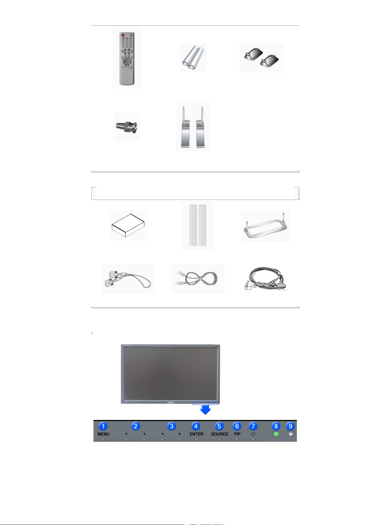
• Please make sure the following items are included with your LCD Display.
If any items are missing, contact your dealer.
Contact a local dealer to buy optional items.
Note
• This stand is not for the Floor Standing Type.
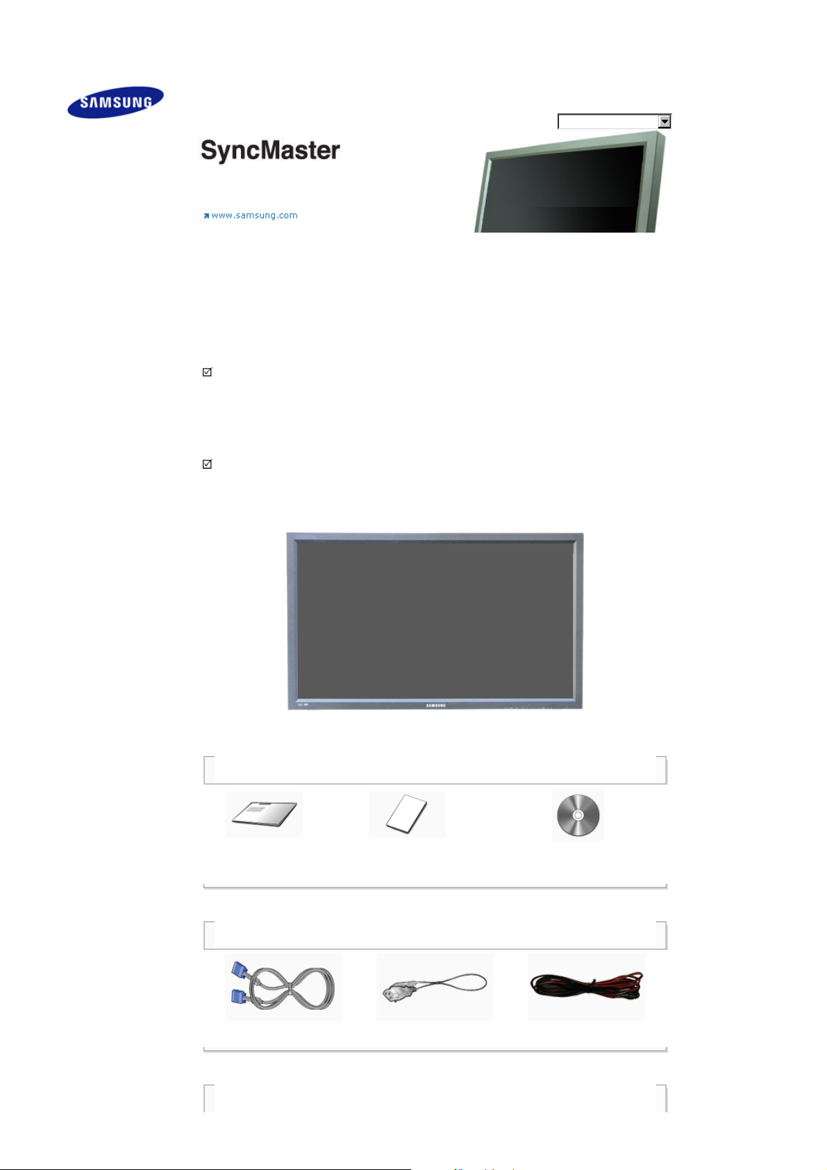
LCD Display
Manuals
Quick Setup Guide
Cables
D-Sub Cable Power Cord Speaker Wire Cable
Other
Warranty Card
(Not available in all locations)
User's Guide, MDC Software,
MagicNet Software
Page 12
Remote Control Batteries (AAA X 2) Cover-Hole
Sold separately
Wall Mount KIT Speaker Set Stand KIT
Front
BNC to RCA
Adaptor Jack
Semi Stand USB Holder & Screw (1EA)
DVI Cable LAN Cable BNC Cable
Your LCD Display
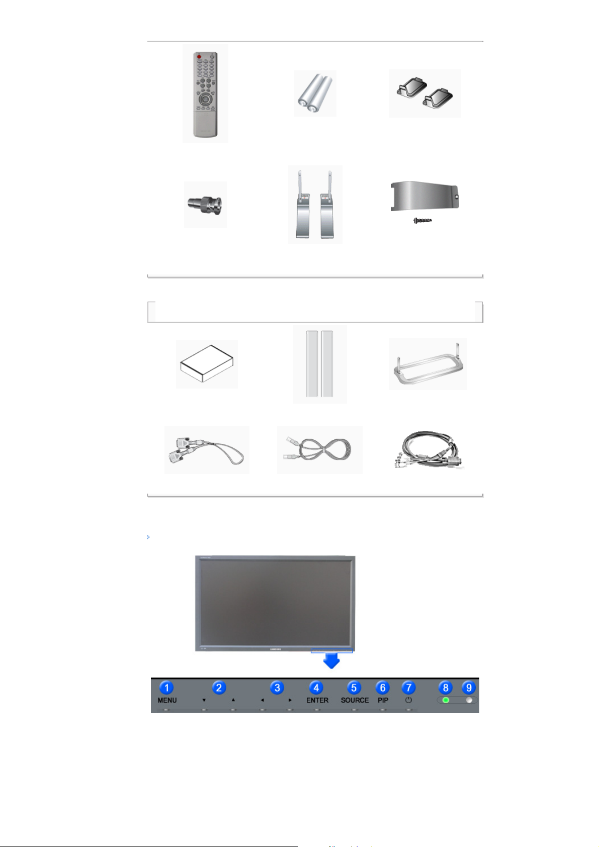
1) MENU
Opens the on-screen menu and exits from the menu or closes the adjustment menu.
2) Navigate buttons (Up-Down buttons)
Moves from one menu item to another vertically or adjusts selected menu values.
3) Adjust buttons (Left-Right buttons)/ Volume buttons
Moves from one menu item to another horizontally or adjusts selected menu values.
Page 13

Adjusts the audio volume.
4) ENTER
Activates a highlighted menu item.
5) SOURCE
Switches from PC mode to Video mode.
Changing the source is only allowed for external devices that are connected to the LCD Display at the time.
[PC] → [BNC] → [DVI] → [AV] → [S-Video] → [Component] → [MagicNet]
>> Click here to see an animation clip.
6) PIP
Push the PIP button to turn the PIP screen On / Off.
More than one PIP cannot overlap on screen as BNC and the component use the same terminal.
>> Click here to see an animation clip.
•
PC
AV / S-Video / Component Mode
•
BNC
AV / S-Video Mode
•
DVI
AV / S-Video / Component Mode
•
AV / S-Video
PC / BNC / DVI Mode
•
Component
PC / DVI Mode
7)
Power button
Turns the LCD Display On/Off.
8) Power indicator
Shows PowerSaver mode by blinking green.
9) Remote Control Sensor
Aim the remote control towards this spot on the LCD Display.
Note
•See PowerSaver described in the manual for further information regarding power saving functions. For
energy conservation, turn your LCD Display OFF when it is not needed or when leaving it unattended for
long periods.
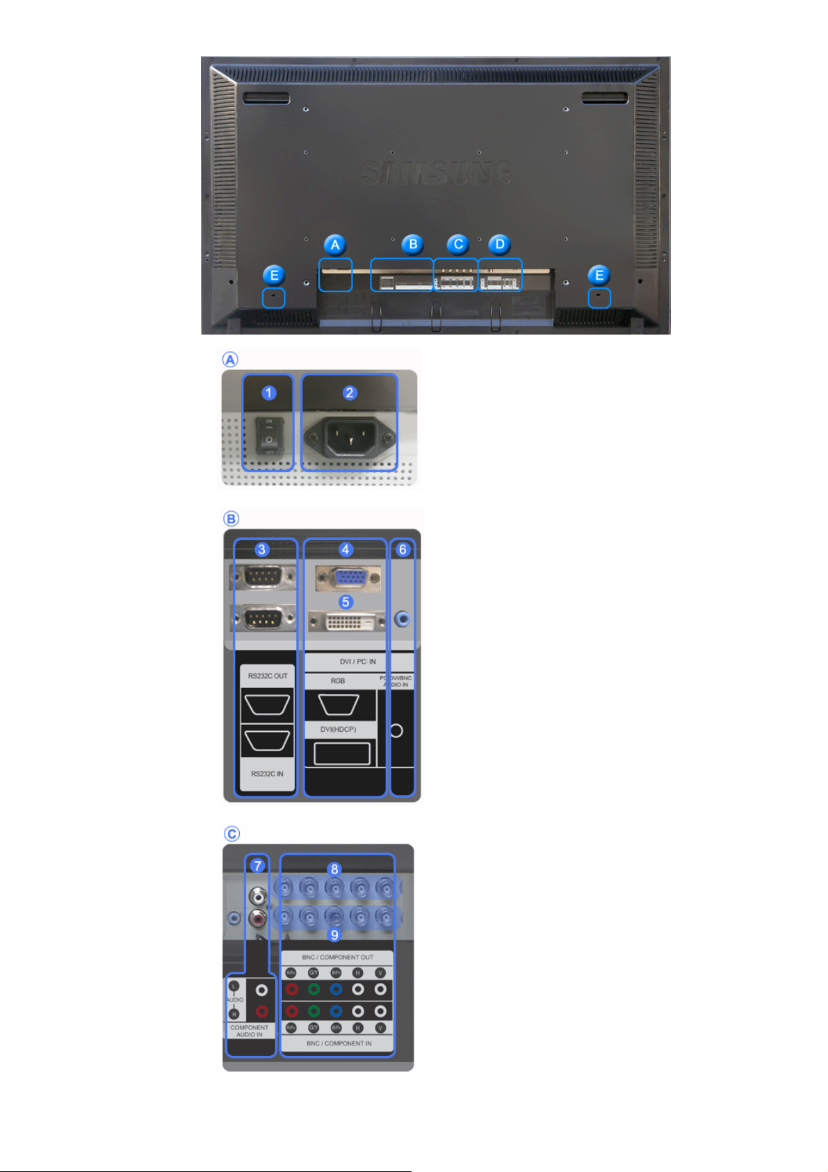
Rear
Note
• For detailed information concerning cable connections, refer to Connecting Cables under Setup. The LCD
Display 's configuration at the back may vary slightly depending on the LCD Display model.
Page 14

1) POWER S/W ON [ | ] / OFF [O]
Switches the LCD Display On/Off.
2) POWER IN
The power cord plugs into the LCD Display and
the wall plug.
3) RS232C OUT/IN (RS232C Serial PORT)
MDC(Multiple Display Control) Program Port
4) DVI / PC IN [DVI(HDCP)] (PC Video
Connection Terminal)
Using a DVI Cable (DVI-D to DVI-D) - DVI
mode (Digital PC)
5) DVI / PC IN [RGB] (PC Video
Connection Terminal)
Using a D-Sub Cable (15 pin D-Sub) - PC
mode (Analog PC)
6) DVI / PC IN [PC/DVI/BNC AUDIO IN]
(PC/DVI/BNC Audio Connection
Terminal (Input))
7) COMPONENT AUDIO IN [L-AUDIO-R]
(Component Audio Connection Terminal
(Input))
R
8) BNC/COMPONENT OUT [R/P
, G/Y, B/PB,
H, V] (BNC/Component Connection
Terminal (Output))
BNC (Analog PC) Connection: connecting the R,
G, B, H, V ports
Component Connection: connecting the P
B
ports
P
R
, Y,
9) BNC/COMPONENT IN [R/PR, G/Y, B/PB, H,
V] (BNC/Component Connection Terminal
(Input))
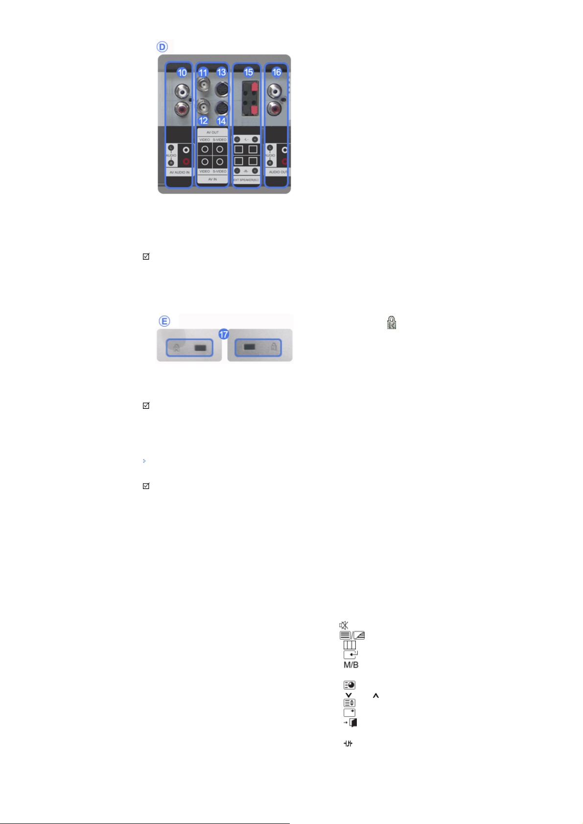
10)
AV AUDIO IN [L-AUDIO-R] (LCD Display
Page 15
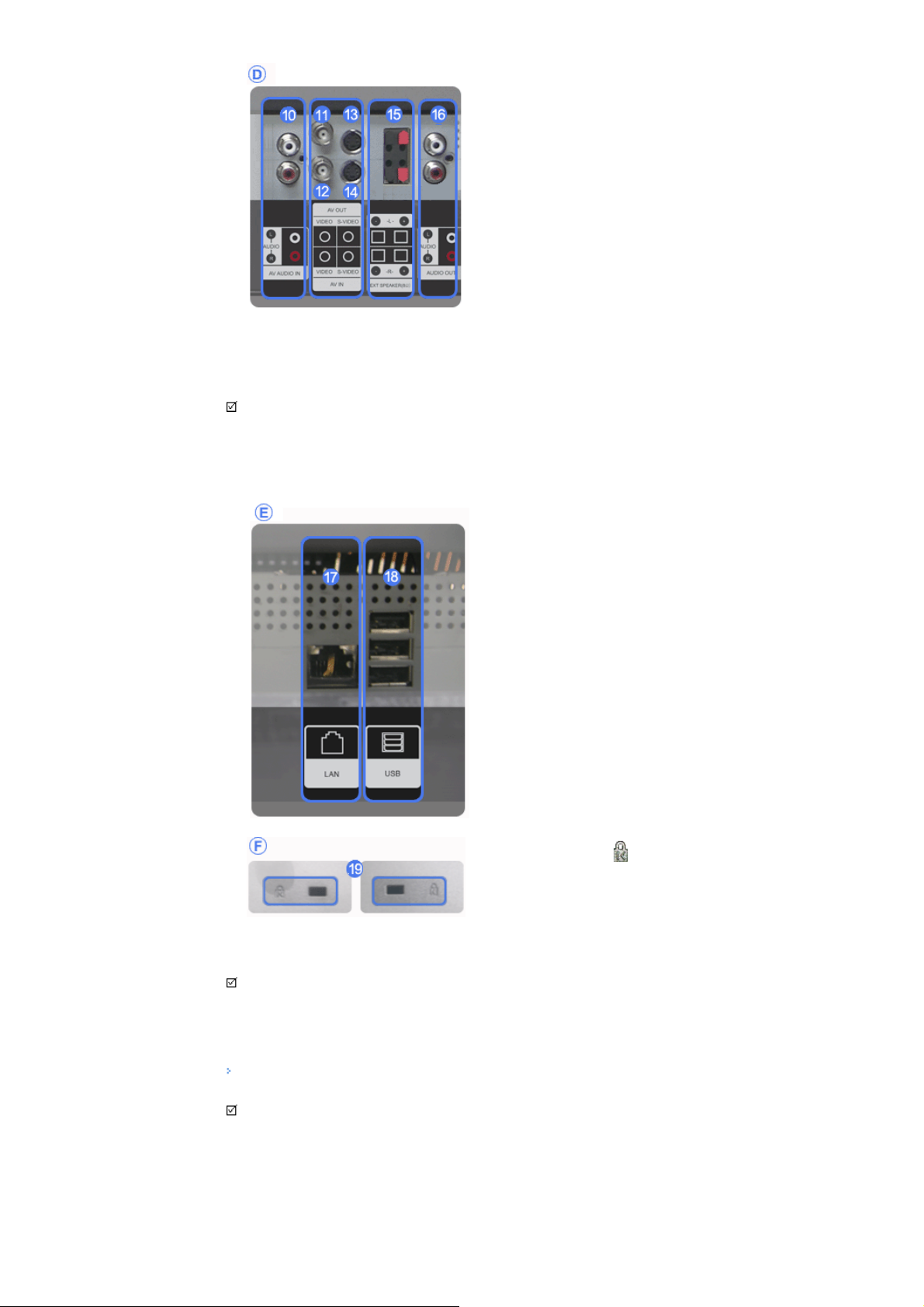
Audio Connection Terminal (Input))
11) AV OUT [VIDEO] (VIDEO Connection
Terminal): AV mode (Output)
12) AV IN [VIDEO] (VIDEO Connection
Terminal) (Input)
13) AV OUT [S-VIDEO] (S-VIDEO Connection
Terminal): S-VIDEO mode (Output)
14) AV IN [S-VIDEO] (S-VIDEO Connection
Terminal) (Input)
15) EXT SPEAKER(8 Ω)[- - L - +, - - R - +] (EXT
Speaker Connection Terminal)
16) AUDIO OUT [L-AUDIO-R] (LCD Display
Audio Connection Terminal (Output))
AUDIO OUT is the terminal for sound output of
PC, DVI or BNC.
Note
• The number of LCD Display s that can be connected to loopout may differ depending on the cables, signal
source etc. With cables where there is no degradation or signal source, up to ten LCD Displays can be
connected.
17) LAN (LAN Connection Terminal)
MS Internet Explorer
18) USB (USB Connection Terminal)
Keyboard / Mouse, Mas s Storage Device
Compatible.
19) Kensington Lock
The Kensington lock is a device used to
physically fix the system to something when
using it in a public place. (The locking device has
to be purchased separately.)
For using a locking device, contact the place
of purchase.
Note
•See Connecting the LCD Display for further information regarding cable connections.
Remote Control
Note
• The performance of the remote control may be affected by a TV or other electronic device operating near
the LCD Display , causing a malfunction due to interference with the frequency.
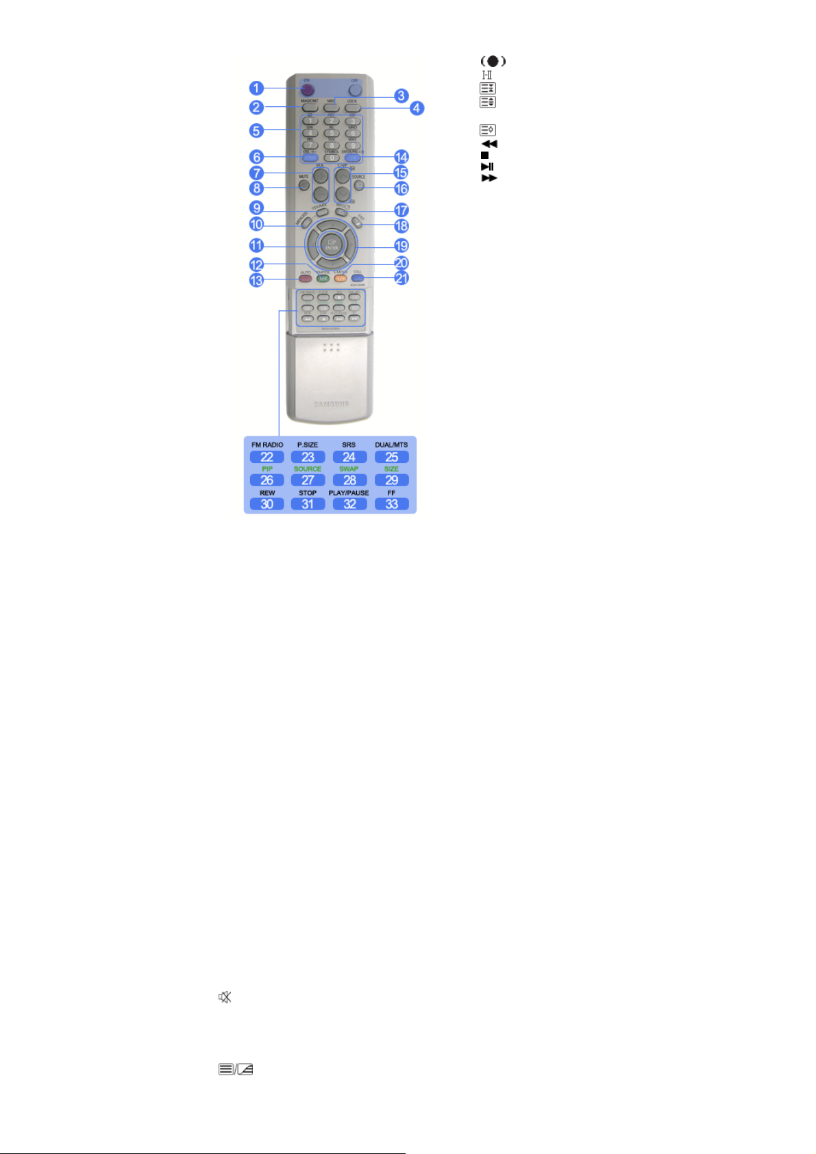
1. ON / OFF
2. MAGICNET
Page 16
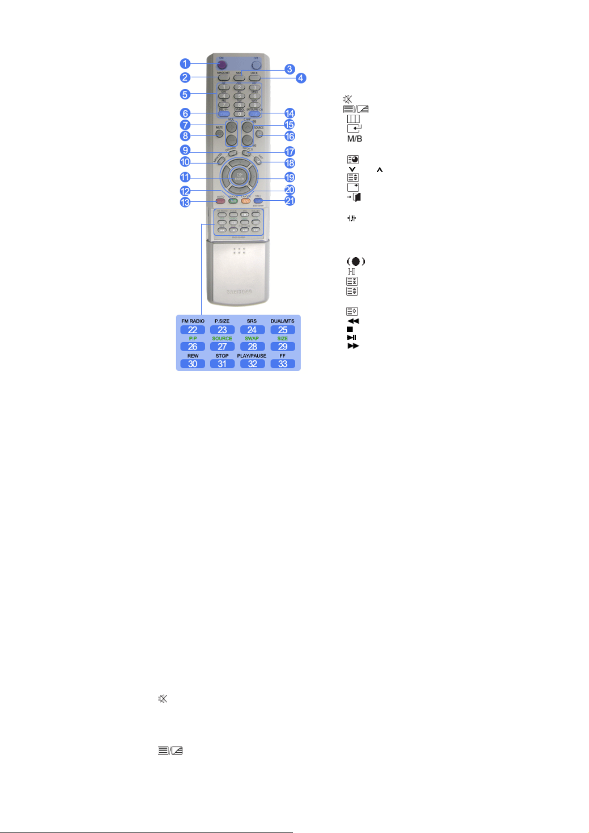
3. MDC
4. LOCK
5. MagicNet buttons
6.+100 -/--
7. VOL
8. MUTE
9. TTX/MIX
10. MENU
11. ENTER
12. P.MODE
13. AUTO
14. PRE-CH
15 . CH/P
16. SOURCE
17. INFO
18. EXIT
19. Up-Down Left-Right buttons
20. S.MODE
21. STILL
22. FM RADIO
23. P.SIZE
24. SRS
25. DUAL/MTS
26. PIP
27. SOURCE
28. SWAP
29. SIZE
30. REW
31. STOP
32. PLAY/PAUSE
33. FF
1) ON / OFF
Turns the LCD Display On/Off.
2) MAGICNET
MagicNet Quick Launch Button.
3) MDC
MDC Quick Launch Button.
4) LOCK
Activates or deactivates all function keys on both the remote control and the LCD Display except for the
Power and LOCK buttons.
5) MagicNet buttons
Used for MagicNet.
• Alphanumeric: Used to enter the Internet address.
• DEL: Functions as the backspace.
• SYMBOL: Used to enter the symbols. (.O_-)
• ENTER: Used to enter values.
6) +100 -/--
Press to select channels over 100.
For example, to select channel 121, press "+100", then press "2" and "1".
- This fuction does not work for this monitor.
7) VOL
Adjusts the audio volume.
MUTE
8)
Pauses (mutes) the audio output temporarily.
This is displayed on the lower left corner of the screen.
The audio resumes if MUTE or - VOL + is pressed in the Mute mode.
9)
TTX/MIX
TV channels provide text information services via teletext.
- This fuction does not work for this monitor.
Page 17

MENU
10)
Opens the on-screen menu and exits from the menu screen or closes the screen adjustment menu.
ENTER
11)
Activates a highlighted menu item.
12)
P.MODE
When you press this button, current picture mode is displayed on the lower center of the screen.
AV / S-Video / Component : P.MODE
The Monitor has four automatic picture settings that are preset at the factory.
Then push button again to circle through available preconfigured modes.
( Dynamic → Standard → Movie → Custom )
PC/DVI/BNC : M/B (MagicBright)
MagicBright™ is a new feature providing the optimum viewing environment depending on the contents of
the image you are watching.
Then push button again to circle through available preconfigured modes.
(Entertain → Internet → Text → Custom )
13) AUTO
Adjusts the screen display automatically in PC mode.
By changing the resolution in the control panel, auto function is performed.
PRE-CH
14)
Returns to the immediately previous channel.
- This fuction does not work for this monitor.
CH/P
15)
In TV mode, selects TV channels.
- This fuction does not work for this monitor.
SOURCE
16)
Changes the video source.
INFO
17)
The current picture information is displayed in the top left corner of the screen.
EXIT
18)
Exits from the menu screen.
19) Up-Down Left-Right buttons
Moves from one menu item to another horizontally, vertically or adjusts selected menu values.
20)
S.MODE
When pressing this button, the current mode is displayed at the bottom centre of the screen.
The LCD Display has a built-in high fidelity stereo amplifier.
Then press the button again to circle through available preconfigured modes.
( Standard → Music → Movie → Speech → Custom )
21) STILL
Press the button once to freeze the screen. Press it again to unfreeze.
22) FM RADIO
Turns the FM Radio on/off.
In PC/DVI mode, sets the SOUND to FM Radio.
In general Video mode, selects FM Radio, and turns off the screen.
In areas where the signal is weak, noise may occur during FM radio broadcasts.
- This fuction does not work for this monitor.
23) P.SIZE
Press to change the screen size.
24)
SRS
25)
SRS
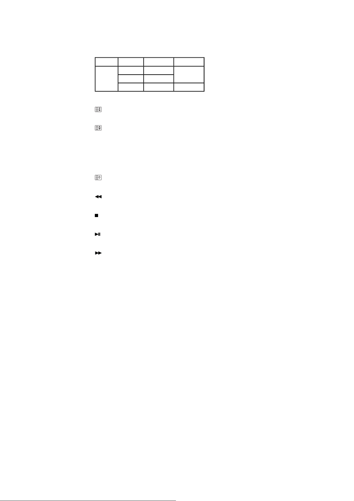
DUAL/MTS
DUAL-
STEREO/MONO, DUAL l / DUAL ll and MONO/NICAM MONO/NICAM STEREO can be operated
depending on the broadcasting type by using the DUAL button on the remote control while watching TV.
Page 18

MTS-
You can select MTS (Multichannel Television Stereo) mode.
FM Stereo
- This fuction does not work for this monitor.
26)
Every time you press the button, a PIP screen appears.
27)
Changes the source of the PIP window signal.
Audio Type MTS/S_Mode Default
Mono Mono
Stereo
SAP
Mono ↔ Stereo
Mono ↔ SAP
PIP
SOURCE
Manual Change
Mono
28) SWAP
Swaps the contents of the PIP and main image.
The image in the PIP window will appear on the main screen, and the main screen image will appear in the
PIP window.
SIZE
29)
Switches the PIP Picture Size.
30)
REW
Rewind
31)
STOP
Stop
32)
PLAY / PAUSE
Play/Pause
33)
FF
Fast forward
© 1995~2007 SAMSUNG. ALL Right Reserved
Page 19

Safety Instructions
Introduction
Package Contents
Your LCD Display
Machanical Layout
Connections
Using the Software
Adjusting the LCD Display
Troubleshooting
Specifications
Information
Appendix
Dodatak
SyncMaster 400PX/460PX
Select Language Main Page
Model
The color and appearance of the product may vary depending on the model, and the product specifications are
subject to change without prior notice for reasons of performance enhancement.
Introduction
Package Contents
Note
ǷȘȐȓȖȎȍȕȐȍ
• Please make sure the following items are included with your LCD Display.
If any items are missing, contact your dealer.
Contact a local dealer to buy optional items.
Note
• This stand is not for the Floor Standing Type.
LCD Display
Manuals
Quick Setup Guide
Cables
D-Sub Cable Power Cord Speaker Wire Cable
Other
Warranty Card
(Not available in all locations)
User's Guide, MDC Software
Page 20
Remote Control Batteries (AAA X 2) Cover-Hole
Sold separately
Wall Mount KIT Speaker Set Stand KIT
Front
BNC to RCA
Adaptor Jack
Semi Stand
DVI Cable LAN Cable BNC Cable
Your LCD Display
1) MENU
Opens the on-screen menu and exits from the menu or closes the adjustment menu.
2) Navigate buttons (Up-Down buttons)
Moves from one menu item to another vertically or adjusts selected menu values.
3) Adjust buttons (Left-Right buttons)/ Volume buttons
Moves from one menu item to another horizontally or adjusts selected menu values.
Page 21

Adjusts the audio volume.
4) ENTER
Activates a highlighted menu item.
5) SOURCE
Switches from PC mode to Video mode.
Changing the source is only allowed for external devices that are connected to the LCD Display at the time.
[PC] → [BNC] → [DVI] → [AV] → [S-Video] → [Component]
>> Click here to see an animation clip.
6) PIP
Push the PIP button to turn the PIP screen On / Off.
More than one PIP cannot overlap on screen as BNC and the component use the same terminal.
>> Click here to see an animation clip.
•
PC
AV / S-Video / Component Mode
•
BNC
AV / S-Video Mode
•
DVI
AV / S-Video / Component Mode
•
AV / S-Video
PC / BNC / DVI Mode
•
Component
PC / DVI Mode
7)
Power button
Turns the LCD Display On/Off.
8) Power indicator
Shows PowerSaver mode by blinking green.
9) Remote Control Sensor
Aim the remote control towards this spot on the LCD Display.
Note
•See PowerSaver described in the manual for further information regarding power saving functions. For
energy conservation, turn your LCD Display OFF when it is not needed or when leaving it unattended for
long periods.
Rear
Note
• For detailed information concerning cable connections, refer to Connecting Cables under Setup. The LCD
Display 's configuration at the back may vary slightly depending on the LCD Display model.
Page 22
1) POWER S/W ON [ | ] / OFF [O]
Switches the LCD Display On/Off.
2) POWER IN
The power cord plugs into the LCD Display and
the wall plug.
3) RS232C OUT/IN (RS232C Serial PORT)
MDC(Multiple Display Control) Program Port
4) DVI / PC IN [DVI(HDCP)] (PC Video
Connection Terminal)
Using a DVI Cable (DVI-D to DVI-D) - DVI
mode (Digital PC)
5) DVI / PC IN [RGB] (PC Video
Connection Terminal)
Using a D-Sub Cable (15 pin D-Sub) - PC
mode (Analog PC)
6) DVI / PC IN [PC/DVI/BNC AUDIO IN]
(PC/DVI/BNC Audio Connection
Terminal (Input))
7) COMPONENT AUDIO IN [L-AUDIO-R]
(Component Audio Connection Terminal
(Input))
R
8) BNC/COMPONENT OUT [R/P
, G/Y, B/PB,
H, V] (BNC/Component Connection
Terminal (Output))
BNC (Analog PC) Connection: connecting the R,
G, B, H, V ports
Component Connection: connecting the P
B
ports
P
R
, Y,
9) BNC/COMPONENT IN [R/PR, G/Y, B/PB, H,
V] (BNC/Component Connection Terminal
(Input))
10)
AV AUDIO IN [L-AUDIO-R] (LCD Display
Page 23
Audio Connection Terminal (Input))
11) AV OUT [VIDEO] (VIDEO Connection
Terminal): AV mode (Output)
12) AV IN [VIDEO] (VIDEO Connection
Terminal) (Input)
13) AV OUT [S-VIDEO] (S-VIDEO Connection
Terminal): S-VIDEO mode (Output)
14) AV IN [S-VIDEO] (S-VIDEO Connection
Terminal) (Input)
15) EXT SPEAKER(8 Ω)[- - L - +, - - R - +] (EXT
Speaker Connection Terminal)
16) AUDIO OUT [L-AUDIO-R] (LCD Display
Audio Connection Terminal (Output))
AUDIO OUT is the terminal for sound output of
PC, DVI or BNC.
Note
• The number of LCD Display s that can be connected to loopout may differ depending on the cables, signal
source etc. With cables where there is no degradation or signal source, up to ten LCD Displays can be
connected.
17) Kensington Lock
The Kensington lock is a device used to
physically fix the system to something when
using it in a public place. (The locking device has
to be purchased separately.)
For using a locking device, contact the place
of purchase.
Note
•See Connecting the LCD Display for further information regarding cable connections.
Remote Control
Note
• The performance of the remote control may be affected by a TV or other electronic device operating near
the LCD Display , causing a malfunction due to interference with the frequency.
1. ON / OFF
2. MAGICNET
3. MDC
4. LOCK
5. MagicNet buttons
6.+100 -/--
7. VOL
8. MUTE
9. TTX/MIX
10. MENU
11. ENTER
12. P.MODE
13. AUTO
14. PRE-CH
15 . CH/P
16. SOURCE
17. INFO
18. EXIT
19. Up-Down Left-Right buttons
20. S.MODE
21. STILL
22. FM RADIO
23. P.SIZE
Page 24
24. SRS
25. DUAL/MTS
26. PIP
27. SOURCE
28. SWAP
29. SIZE
30. REW
31. STOP
32. PLAY/PAUSE
33. FF
1) ON / OFF
Turns the LCD Display On/Off.
2) MAGICNET
MagicNet Quick Launch Button.
- This fuction does not work for this monitor.
3) MDC
MDC Quick Launch Button.
4) LOCK
Activates or deactivates all function keys on both the remote control and the LCD Display except for the
Power and LOCK buttons.
5) MagicNet buttons
Used for MagicNet.
• Alphanumeric: Used to enter the Internet address.
• DEL: Functions as the backspace.
• SYMBOL: Used to enter the symbols. (.O_-)
• ENTER: Used to enter values.
- This fuction does not work for this monitor.
6) +100 -/--
Press to select channels over 100.
For example, to select channel 121, press "+100", then press "2" and "1".
- This fuction does not work for this monitor.
7) VOL
Adjusts the audio volume.
MUTE
8)
Pauses (mutes) the audio output temporarily.
This is displayed on the lower left corner of the screen.
The audio resumes if MUTE or - VOL + is pressed in the Mute mode.
9)
TTX/MIX
Page 25

TV channels provide text information services via teletext.
- This fuction does not work for this monitor.
MENU
10)
Opens the on-screen menu and exits from the menu screen or closes the screen adjustment menu.
ENTER
11)
Activates a highlighted menu item.
12)
P.MODE
When you press this button, current picture mode is displayed on the lower center of the screen.
AV / S-Video / Component : P.MODE
The Monitor has four automatic picture settings that are preset at the factory.
Then push button again to circle through available preconfigured modes.
( Dynamic → Standard → Movie → Custom )
PC/DVI/BNC : M/B (MagicBright)
MagicBright™ is a new feature providing the optimum viewing environment depending on the contents of
the image you are watching.
Then push button again to circle through available preconfigured modes.
(Entertain → Internet → Text → Custom )
13) AUTO
Adjusts the screen display automatically in PC mode.
By changing the resolution in the control panel, auto function is performed.
PRE-CH
14)
Returns to the immediately previous channel.
- This fuction does not work for this monitor.
CH/P
15)
In TV mode, selects TV channels.
- This fuction does not work for this monitor.
SOURCE
16)
Changes the video source.
INFO
17)
The current picture information is displayed in the top left corner of the screen.
EXIT
18)
Exits from the menu screen.
19) Up-Down Left-Right buttons
Moves from one menu item to another horizontally, vertically or adjusts selected menu values.
20)
S.MODE
When pressing this button, the current mode is displayed at the bottom centre of the screen.
The LCD Display has a built-in high fidelity stereo amplifier.
Then press the button again to circle through available preconfigured modes.
( Standard → Music → Movie → Speech → Custom )
21) STILL
Press the button once to freeze the screen. Press it again to unfreeze.
22) FM RADIO
Turns the FM Radio on/off.
In PC/DVI mode, sets the SOUND to FM Radio.
In general Video mode, selects FM Radio, and turns off the screen.
In areas where the signal is weak, noise may occur during FM radio broadcasts.
- This fuction does not work for this monitor.
23) P.SIZE
Press to change the screen size.
24)
SRS
25)
SRS
DUAL/MTS
DUAL-
Page 26
STEREO/MONO, DUAL l / DUAL ll and MONO/NICAM MONO/NICAM STEREO can be operated
depending on the broadcasting type by using the DUAL button on the remote control while watching TV.
MTS-
You can select MTS (Multichannel Television Stereo) mode.
FM Stereo
- This fuction does not work for this monitor.
26)
Every time you press the button, a PIP screen appears.
27)
Changes the source of the PIP window signal.
Audio Type MTS/S_Mode Default
Mono Mono
Stereo
SAP
Mono ↔ Stereo
Mono ↔ SAP
PIP
SOURCE
Manual Change
Mono
28) SWAP
Swaps the contents of the PIP and main image.
The image in the PIP window will appear on the main screen, and the main screen image will appear in the
PIP window.
SIZE
29)
Switches the PIP Picture Size.
30) REW
Rewind
31)
STOP
Stop
32) PLAY / PAUSE
Play/Pause
33)
FF
Fast forward
© 1995~2007 SAMSUNG. ALL Right Reserved
Page 27
SyncMaster 400PXn/400PX
Mechanical Lay-out | Monitor Head | Stand | Speaker | Installation VESA Bracket | Wall Bracket Installation
1. Mechanical Lay-out
Dodatak
ǷȘȐȓȖȎȍȕȐȍ
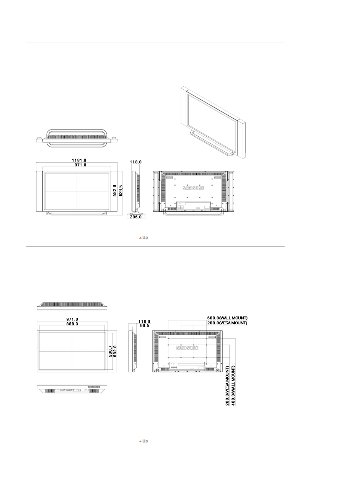
2. Monitor Head
Page 28

3. Stand
4. Speaker
5. Installation VESA Bracket
z When installing VESA, make sure to comply with the international VESA standards.
z Purchasing VESA Bracket and Installation Information : Please contact your nearest Samsung Distributor to place
an order. After your order is placed, installation professionals will visit you and install the bracket.
z At least 2 persons are needed in order to move the LCD Monitor.
z Samsung is not responsible for any product damage or any injury caused by installation at customer's discretion.
Dimensions
Page 29

For securing the bracket on a wall, use only machine screws of 6 mm diameter and 8 to 12 mm length.
6. Wall Bracket Installation
z Contact a technician for installing the wall bracket.
z Samsung Electronics is not responsible for any damages to the product or harm to customers when the
installation is done by the customer.
z
This product is for installing on cement walls. The product may not stay in place when installed on plaster or wood.
Components
Only use the components and accessories shipped with the product.
`
Wall Bracket
(1)
(Left 1, Right 1)
Wall Bracket Assembly
Hinge
Plastic Hanger
(4)
Screw(A)
(11)
Insert and tighten the Captive Screw in the
direction of the arrow.
When done, mount the wall bracket on the wall.
A. Captive Screw
B. Wall Bracket
C. Hinge (Left)
D. Hinge (Right)
Screw(B)
(4)
Anchor
(11)
Page 30
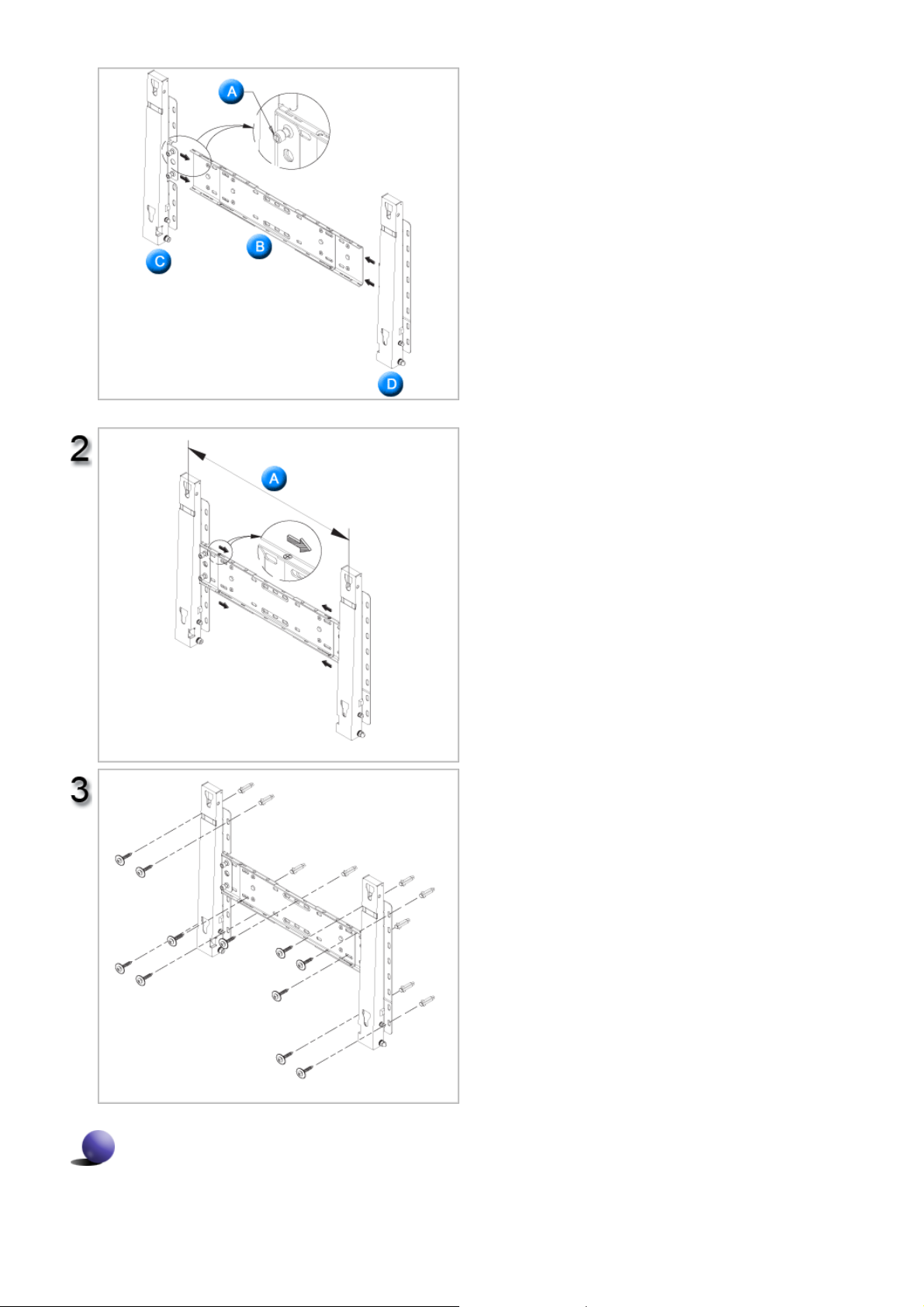
There are two hinges(left and right). Use the correct one.
Before drilling into the wall, check if the length
between the two locking holes at the back of the
product is correct.
If the length is too short or long, loosen all or
some of the 4screws on the wall bracket to adjust
the length.
A. Length between the two locking holes
Check the installation diagram and mark the drill
points on the wall. Use the 5.0 mm bit to drill
holes deeper than 35 mm. Fix each anchor in the
corresponding hole.
Match each of the brackets and hinge holes to
the corresponding anchor holes and insert and
tighten the 11 screws A.
To mount the product on the wall bracket
The shape of the product may vary depending on the model. (The assemblies of the plastic hanger and the
screw are the same)
Page 31

Remove the 4 screws on the back of the
product.
Insert the screw B into the plastic hanger.
1. Mount the product on the wall bracket and
make sure it is properly fixed to the left and
right plastic hangers.
2. Be careful when installing the product on the
bracket as fingers can be caught in the holes.
3. Make sure the wall bracket is securely fixed to
the wall, or the product may not stay in place
after installation.
Tighten the 4 screws in step 2 (plastic hanger +
screw B)to the rear holes of the product.
Remove safety pin (3) and insert the 4 product
holders into the corresponding bracket holes (1).
Then place the product(2) so that it is firmly fixed
to the bracket. Make sure to re-insert and tighten
the safety pin (3) to securely hold the product to
the bracket.
A. Monitor
B. Wall Bracket
C. Wall
Wall Bracket Angle Adjustment
Adjust the bracket angle to -2°before installing it on the wall.
Page 32

1. Fix the product to the wall bracket.
2. Hold the product at the top in the center and pull it forward
(direction of the arrow) to adjust the angle.
3. You can adjust the bracket angle between -2°and 15 °.
Make sure to use the top center, and not the
leftor the right side of the product to adjust the
angle.
Page 33

SyncMaster 460PXn/460PX
Mechanical Lay-out | Monitor Head | Stand | Speaker | Installation VESA Bracket | Wall Bracket Installation
1. Mechanical Lay-out
Dodatak
ǷȘȐȓȖȎȍȕȐȍ
2. Monitor Head
Page 34

3. Stand
4. Speaker
5. Installation VESA Bracket
z When installing VESA, make sure to comply with the international VESA standards.
z Purchasing VESA Bracket and Installation Information : Please contact your nearest Samsung Distributor to place
an order. After your order is placed, installation professionals will visit you and install the bracket.
z At least 2 persons are needed in order to move the LCD Monitor.
z Samsung is not responsible for any product damage or any injury caused by installation at customer's discretion.
Dimensions
Page 35

For securing the bracket on a wall, use only machine screws of 6 mm diameter and 8 to 12 mm length.
6. Wall Bracket Installation
z Contact a technician for installing the wall bracket.
z Samsung Electronics is not responsible for any damages to the product or harm to customers when the
installation is done by the customer.
z
This product is for installing on cement walls. The product may not stay in place when installed on plaster or wood.
Components
Only use the components and accessories shipped with the product.
`
Wall Bracket
(1)
(Left 1, Right 1)
Wall Bracket Assembly
Hinge
Plastic Hanger
(4)
Screw(A)
(11)
Insert and tighten the Captive Screw in the
direction of the arrow.
When done, mount the wall bracket on the wall.
A. Captive Screw
B. Wall Bracket
C. Hinge (Left)
D. Hinge (Right)
Screw(B)
(4)
Anchor
(11)
Page 36

There are two hinges(left and right). Use the correct one.
Before drilling into the wall, check if the length
between the two locking holes at the back of the
product is correct.
If the length is too short or long, loosen all or
some of the 4screws on the wall bracket to adjust
the length.
A. Length between the two locking holes
Check the installation diagram and mark the drill
points on the wall. Use the 5.0 mm bit to drill
holes deeper than 35 mm. Fix each anchor in the
corresponding hole.
Match each of the brackets and hinge holes to
the corresponding anchor holes and insert and
tighten the 11 screws A.
To mount the product on the wall bracket
The shape of the product may vary depending on the model. (The assemblies of the plastic hanger and the
screw are the same)
Page 37

Remove the 4 screws on the back of the
product.
Insert the screw B into the plastic hanger.
1. Mount the product on the wall bracket and
make sure it is properly fixed to the left and
right plastic hangers.
2. Be careful when installing the product on the
bracket as fingers can be caught in the holes.
3. Make sure the wall bracket is securely fixed to
the wall, or the product may not stay in place
after installation.
Tighten the 4 screws in step 2 (plastic hanger +
screw B)to the rear holes of the product.
Remove safety pin (3) and insert the 4 product
holders into the corresponding bracket holes (1).
Then place the product(2) so that it is firmly fixed
to the bracket. Make sure to re-insert and tighten
the safety pin (3) to securely hold the product to
the bracket.
A. Monitor
B. Wall Bracket
C. Wall
Wall Bracket Angle Adjustment
Adjust the bracket angle to -2°before installing it on the wall.
Page 38

1. Fix the product to the wall bracket.
2. Hold the product at the top in the center and pull it forward
(direction of the arrow) to adjust the angle.
3. You can adjust the bracket angle between -2°and 15 °.
Make sure to use the top center, and not the
leftor the right side of the product to adjust the
angle.
Page 39

Safety Instructions
Introduction
Connections
Installing the Stand KIT
Connecting the LCD
Display
Using the Software
Adjusting the LCD Display
Troubleshooting
Specifications
Information
Appendix
Dodatak
SyncMaster 400PXn/460PXn
Select Language Main Page
Model
The color and appearance of the product may vary depending on the model, and the product specifications are
subject to change without prior notice for reasons of performance enhancement.
Connections
Installing the Stand KIT
Note
ǷȘȐȓȖȎȍȕȐȍ
• Only the supplied bolts should be used.
Caution
Samsung Electronics will not be responsible for damages caused by using a base other than those
specified.
Installing the Semi Stand
Left stand
Caution
Make sure to install the stand with the Caution label
folded backwards.
Right stand
1) A 'Cover-Protector' is used to protect the hole at the bottom of the LCD Display , where the stand is
inserted. Be sure to remove the 'Cover-Protector' when attaching the provided Semi Stand or Stand KIT
(sold separately) and cover the hole using the 'Cover-Hole' when attaching the wall mount kit.
2) Set up the left and right stands respectively.
3) Insert the stand into the hole at the bottom of the LCD Display.
Insert the screw into the hole indicated and tighten it. (M4 x L15)
Caution
Page 40

This stand is designed for adjusting the screen angle. The company is not responsible for any problem
caused when using this stand. Under no circumstances use the product as a stand for placing something on.
Installing the Stand KIT (sold separately)
1) A 'Cover-Protector' is used to protect the hole at the bottom of the LCD Display , where the stand is
inserted. Be sure to remove the 'Cover-Protector' when attaching the provided Semi Stand or Stand KIT
(sold separately) and cover the hole using the 'Cover-Hole' when attaching the wall mount kit.
2) Ensure that the parts are inserted in the right direction and in the right place. (M4 × L15)
3) Insert the stand into the hole at the bottom of the LCD Display.
4) Insert the screw into the hole indicated and tighten it. (M4 × L15)
Connecting the LCD Display
Using a Power cord with Earth
In the event of failure, the earth lead may cause electric shock. Make sure to wire the earth lead in
correctly, before connecting the AC power. When un-wiring the earth lead, make sure to disconnect
the AC power in advance.
Note
• AV input devices such as DVD players, VCR's or camcorders as well as your computer can be connected
to the LCD Display. For detailed information on connecting AV input devices, refer to the User Controls
under Adjusting Your LCD Display.
Connecting to a Computer
Page 41

1) Connect the power cord for your LCD Display to the power port on the back of the LCD Display.
Trun on the power switch.
2) There are 3 ways to connect the D-sub to your LCD Display.
Choose one of the following:
2-1) Using the D-sub (Analog) connector on the video card.
Connect the D-sub to the 15-pin, RGB port on the back of your LCD Display and the 15 pin D-sub
Port on the computer.
2-2) Using the DVI (Digital) connector on the video card.
Connect the DVI Cable to the DVI(HDCP) port on the back of your LCD Display and the DVI port
on the computer.
2-3) Using the BNC (Analog) connector on the video card.
Connect the BNC Cable to the BNC/COMPONENT IN - R, G, B, H, V ports on the back of your
LCD Display and the 15 pin D-sub Port on the computer.
3) Connect the audio cable for your LCD Display to the audio port on the back of your computer.
4) Turn on both your computer and the LCD Display.
Note
• The DVI cable or BNC cable is optional.
Contact a local Samsung Electronics Service Center to buy optional items.
Page 42

Connecting Digital DVD
Note
• Input devices such as digital DVD are connected to the DVI IN terminal of the monitor using the DVI cable.
• Then, start the DVD with a DVD disc inserted.
• Select Digital using the SOURCE button.
Note
• The monitor has DVI IN connection terminals to connect DVI input devices digital DVD.
Connecting to a VCR
1) AV input devices such as VCRs or Camcorders are connected via the AV IN [VIDEO] or AV IN [S-VIDEO]
of the LCD Display using an S-VHS or BNC cable.
2) Connect the Audio (L) and Audio (R) terminals of a VCR or Camcorders to the LCD Display 's AV AUDIO
IN [L-AUDIO-R] using audio cables.
3) Select AV or S-Video for a connected VCR or Camcorder using the SOURCE button on the front of the
LCD Display or on the remote control.
4) Then, start the VCR or Camcorders with a tape inserted.
Note
• The S-VHS or BNC cable is optional.
Connecting to a DVD Player
Page 43

1) Connect a set of audio cables between the COMPONENT AUDIO IN [L-AUDIO-R] on the LCD Display and
the AUDIO OUT jacks on the DVD player.
2) Connect a Component cable between the BNC/COMPONENT IN - P
R
, Y, PB jacks on the DVD player.
the P
R, Y, PB port on the LCD Display and
3) Select Component for the connection to a DVD player using the SOURCE button on the front of the LCD
Display or on the remote control.
4) Then, start the DVD Player with a DVD disc inserted.
Note
• A component cable is optional.
For an explanation of Component video, consult your DVD manual.
Connecting to a Camcorder
1) Locate the A/V output jacks on the camcorder. They are usually found on the side or back of the
camcorder.
Connect a set of audio cables between the AUDIO OUTPUT jacks on the camcorder and the AV AUDIO IN
[L-AUDIO-R] on the LCD Display.
2) Connect a video cable between the VIDEO OUTPUT jack on the camcorder and the AV IN [VIDEO] on the
LCD Display.
3) Select AV for the Camcorder connection using the SOURCE button on the front of the LCD Display or on
the remote control.
4) Then, start the Camcorders with a tape inserted.
Note
•
The audio-video cables shown here are usually included with a Camcorder.
Page 44

(If not, check your local electronics store.)
If your camcorder is stereo, you need to connect a set of two cables.
Connecting to a DTV Set Top Box
Note
• The connections for a typical Set Top Box are shown below.
1) Connect a set of audio cables between the COMPONENT AUDIO IN [L-AUDIO-R] on the LCD Display and
the AUDIO OUT jacks o n the Set Top Box.
2) Connect a Component cable between the BNC / COMPONENT IN - P
R
, Y, PB jacks on the Set Top Box.
the P
R, Y, PB port on the LCD Display and
3) Select Component for the connection to a DTV Set Top Box using the SOURCE button on the front of the
LCD Display or on the remote control.
Note
• For an explanation of Component video, see your Set Top Box owner's manual.
Connecting Speakers
1) Fasten the SET and the speaker using the screws.
* Mount the speaker set without the speaker stand.
2)
Connect the speaker connection cable between the speaker connection jack on the back of the SET and
Page 45

the speaker connection jack on the back of the speaker.
Note
• Do not move the SET while the SET is connected to the speakers.
The speaker-bracket for connecting the SET speaker my become damaged.
Connecting to an Audio System
1) Connect a set of audio cables between the AUX L, R jacks on the AUDIO SYSTEM and the AUDIO OUT
[L-AUDIO-R] on LCD Display.
Connecting a LAN Cable
1) Connect the LAN cable.
Connecting a USB device
Page 46

1) You can connect USB devices such as a mouse or keyboard.
Using a USB Holder
When using a small external device such as a portable memory stick and it is connected to the USB terminal
at the back of your monitor, it is exposed to the possiblity of theft or loss. By installing a USB holder after the
installation of an external device, you can prevent theft or loss.
1) Insert part of your USB holder into the groove in part at the back of your monitor.
Page 47

2) Align part of your USB holder with the groove at the bottom of part at the back of your monitor.
Align part of your USB holder with the bottom of part at the back of your monitor.
3) Insert a screw into the groove aligned in step [2], and fasten it.
Align with and use a screw to fix them.
© 1995~2007 SAMSUNG. ALL Right Reserved
Page 48

Safety Instructions
Introduction
Connections
Installing the Stand KIT
Connecting the LCD
Display
Using the Software
Adjusting the LCD Display
Troubleshooting
Specifications
Information
Appendix
Dodatak
SyncMaster 400PX/460PX
Select Language Main Page
Model
The color and appearance of the product may vary depending on the model, and the product specifications are
subject to change without prior notice for reasons of performance enhancement.
Connections
Installing the Stand KIT
Note
ǷȘȐȓȖȎȍȕȐȍ
• Only the supplied bolts should be used.
Caution
Samsung Electronics will not be responsible for damages caused by using a base other than those
specified.
Installing the Semi Stand
Left stand
Caution
Make sure to install the stand with the Caution label
folded backwards.
Right stand
1) A 'Cover-Protector' is used to protect the hole at the bottom of the LCD Display , where the stand is
inserted. Be sure to remove the 'Cover-Protector' when attaching the provided Semi Stand or Stand KIT
(sold separately) and cover the hole using the 'Cover-Hole' when attaching the wall mount kit.
2) Set up the left and right stands respectively.
3) Insert the stand into the hole at the bottom of the LCD Display.
Insert the screw into the hole indicated and tighten it. (M4 x L15)
Caution
Page 49

This stand is designed for adjusting the screen angle. The company is not responsible for any problem
caused when using this stand. Under no circumstances use the product as a stand for placing something on.
Installing the Stand KIT (sold separately)
1) A 'Cover-Protector' is used to protect the hole at the bottom of the LCD Display , where the stand is
inserted. Be sure to remove the 'Cover-Protector' when attaching the provided Semi Stand or Stand KIT
(sold separately) and cover the hole using the 'Cover-Hole' when attaching the wall mount kit.
2) Ensure that the parts are inserted in the right direction and in the right place. (M4 × L15)
3) Insert the stand into the hole at the bottom of the LCD Display.
4) Insert the screw into the hole indicated and tighten it. (M4 × L15)
Connecting the LCD Display
Using a Power cord with Earth
In the event of failure, the earth lead may cause electric shock. Make sure to wire the earth lead in
correctly, before connecting the AC power. When un-wiring the earth lead, make sure to disconnect
the AC power in advance.
Note
• AV input devices such as DVD players, VCR's or camcorders as well as your computer can be connected
to the LCD Display. For detailed information on connecting AV input devices, refer to the User Controls
under Adjusting Your LCD Display.
Connecting to a Computer
Page 50

1) Connect the power cord for your LCD Display to the power port on the back of the LCD Display.
Trun on the power switch.
2) There are 3 ways to connect the D-sub to your LCD Display.
Choose one of the following:
2-1) Using the D-sub (Analog) connector on the video card.
Connect the D-sub to the 15-pin, RGB port on the back of your LCD Display and the 15 pin D-sub
Port on the computer.
2-2) Using the DVI (Digital) connector on the video card.
Connect the DVI Cable to the DVI(HDCP) port on the back of your LCD Display and the DVI port
on the computer.
2-3) Using the BNC (Analog) connector on the video card.
Connect the BNC Cable to the BNC/COMPONENT IN - R, G, B, H, V ports on the back of your
LCD Display and the 15 pin D-sub Port on the computer.
3) Connect the audio cable for your LCD Display to the audio port on the back of your computer.
4) Turn on both your computer and the LCD Display.
Note
• The DVI cable or BNC cable is optional.
Contact a local Samsung Electronics Service Center to buy optional items.
Page 51

Connecting Digital DVD
Note
• Input devices such as digital DVD are connected to the DVI IN terminal of the monitor using the DVI cable.
• Then, start the DVD with a DVD disc inserted.
• Select Digital using the SOURCE button.
Note
• The monitor has DVI IN connection terminals to connect DVI input devices digital DVD.
Connecting to a VCR
1) AV input devices such as VCRs or Camcorders are connected via the AV IN [VIDEO] or AV IN [S-VIDEO]
of the LCD Display using an S-VHS or BNC cable.
2) Connect the Audio (L) and Audio (R) terminals of a VCR or Camcorders to the LCD Display 's AV AUDIO
IN [L-AUDIO-R] using audio cables.
3) Select AV or S-Video for a connected VCR or Camcorder using the SOURCE button on the front of the
LCD Display or on the remote control.
4) Then, start the VCR or Camcorders with a tape inserted.
Note
• The S-VHS or BNC cable is optional.
Connecting to a DVD Player
Page 52

1) Connect a set of audio cables between the COMPONENT AUDIO IN [L-AUDIO-R] on the LCD Display and
the AUDIO OUT jacks on the DVD player.
2) Connect a Component cable between the BNC/COMPONENT IN - P
R
, Y, PB jacks on the DVD player.
the P
R, Y, PB port on the LCD Display and
3) Select Component for the connection to a DVD player using the SOURCE button on the front of the LCD
Display or on the remote control.
4) Then, start the DVD Player with a DVD disc inserted.
Note
• A component cable is optional.
For an explanation of Component video, consult your DVD manual.
Connecting to a Camcorder
1) Locate the A/V output jacks on the camcorder. They are usually found on the side or back of the
camcorder.
Connect a set of audio cables between the AUDIO OUTPUT jacks on the camcorder and the AV AUDIO IN
[L-AUDIO-R] on the LCD Display.
2) Connect a video cable between the VIDEO OUTPUT jack on the camcorder and the AV IN [VIDEO] on the
LCD Display.
3) Select AV for the Camcorder connection using the SOURCE button on the front of the LCD Display or on
the remote control.
4) Then, start the Camcorders with a tape inserted.
Note
•
The audio-video cables shown here are usually included with a Camcorder.
Page 53

(If not, check your local electronics store.)
If your camcorder is stereo, you need to connect a set of two cables.
Connecting to a DTV Set Top Box
Note
• The connections for a typical Set Top Box are shown below.
1) Connect a Component cable between the BNC / COMPONENT IN - PR, Y, PB port on the LCD Display and
R
, Y, PB jacks on the Set Top Box.
the P
2) Connect a set of audio cables between the COMPONENT AUDIO IN [L-AUDIO-R] on the LCD Display and
the AUDIO OUT jacks o n the Set Top Box.
3) Select Component for the connection to a DTV Set Top Box using the SOURCE button on the front of the
LCD Display or on the remote control.
Note
• For an explanation of Component video, see your Set Top Box owner's manual.
Connecting Speakers
1) Fasten the SET and the speaker using the screws.
* Mount the speaker set without the speaker stand.
2)
Connect the speaker connection cable between the speaker connection jack on the back of the SET and
Page 54

the speaker connection jack on the back of the speaker.
Note
• Do not move the SET while the SET is connected to the speakers.
The speaker-bracket for connecting the SET speaker my become damaged.
Connecting to an Audio System
1) Connect a set of audio cables between the AUX L, R jacks on the AUDIO SYSTEM and the AUDIO OUT
[L-AUDIO-R] on LCD Display.
© 1995~2007 SAMSUNG. ALL Right Reserved
Page 55

Safety Instructions
Introduction
Connections
Using the Software
Installation MagicNet
MDC
MagicNet
Adjusting the LCD Display
Troubleshooting
Specifications
Information
Appendix
Dodatak
SyncMaster 400PXn/460PXn
Select Language Main Page
Model
The color and appearance of the product may vary depending on the model, and the product specifications are
subject to change without prior notice for reasons of performance enhancement.
Using the Software
Installation MagicNet
Installation
ǷȘȐȓȖȎȍȕȐȍ
1. Insert the installation CD into the CD-ROM drive.
2. Click the MagicNet installation file.
3. When the InstallShield Wizard window appears, click "Next."
4. Select "I agree to the terms of the license agreement" to accept the terms of use.
5. You are required to log in to the MagicNet Server program. Please enter the password to login. The
password cannot be changed when you are logged in.
Page 56

6. Choose a folder to install the MagicNet program.
7. Click "Install."
8. The "Installation Status" window appears.
Page 57

9. It is recommended restarting the system for the normal operation of the MagicNet Server program.
Click "Finish."
10. When the installation is complete, the MagicNet executable icon appears on your desktop.
11. Double-click the icon to start the program.
System Requirements
CPU RAM Ethernet OS Application
Minimum P1.8 256M
100M/1G
Recommended P3.0Ghz 512M
Windows XP
Windows 2000
(Service Pack 4)
© 1995~2007 SAMSUNG. ALL Right Reserved
WMP 9 or later
Page 58

Introduction
A Multiple Display Control (MDC) is an application allowing various displays to be easily and simultaneously
operated on a PC. RS-232C, a standard of serial communication, is used for the communication between a PC and
a display. Therefore, a serial cable should be connected between the serial port on a PC and the serial port on a
display.
Main Screen
Click Start > Program > Samsung > MDC System to start the program.
Select a set to see the volume of the selected set within the slider.
Page 59

Main Icons Select Button
Remocon Info Grid
Safety Lock Display Selection
Port Selection Control Tools
1. Use the main icons to switch into each screen.
2. Allows you to enable or disable the remote control signal receiving function of the display unit.
3. Set the Safety Lock function.
When setting the Lock function, you can only operate power and lock buttons on the remote control and set.
4. The setting for the PC Serial Port can change. The original value is COM1.
5. Click Select all or Clear to select or clear all displays.
6. Use Grid to view brief information on selected display.
7. Select a display from Display Selection.
8. Use Control Tools to control displays.
<Note> The remote control Enable/Disable function operates whether or not the power is On/Off, and this
applies to all displays connected to the MDC. However, regardless of the status at the time the MDC is
shut down, the remote control signal receiving function of all displays is initialized to Enable when the
MDC is closed.
Port Selection
Page 60

1. The Multiple Display Control is originally set to COM1.
2. If any port other than COM1 is used, COM1 through COM4 can be selected in the Port Selection Menu.
3. If the exact port name that is connected to the LCD Display using a serial cable is not selected, communication will
be unavailable.
4. The selected port is stored in the program and used for the next program as well.
Power Control
1. Click Power Control of the main icons and the Power Control screen appears.
Page 61

Info Grid shows some basic information necessary to Power Control.
1) (Power Status)
2) Input
3) Image Size
4) On Timer
5) Off Timer
2. Use the Select All button or Check Box to choose a display to control.
Power Control allows controlling some of the functions of the selected display.
1)
Power On/Off
Page 62

- Turns the power of the selected display On/Off.
2) Volume
- Controls the volume level of the selected display.
It receives the volume value of the selected display from the sets and displays it in the slider.
(When you cancel the selection or choose Select All, the value returns to the default value 10)
3)
(Mute On/Off)
- Turns on/off the Mute function of the selected display.
When selecting one set at a time, turn on the Mute function for the selected set.
The Mute function is disabled automatically when you adjust the volume level.
(The values return to the default settings when you undo the selections or choose "Select All".)
The Power Control feature is available for all displays.
The Volume Control and Mute features are available only for the displays whose power status is ON.
Input Source
1. Click Input Source of the main icons and the Input Source control screen appears.
Click Select All or use Check Box to select a display to control.
• TV Mode
• PC Mode
Page 63

Info Grid shows some basic information necessary to Input Source Control.
V
1) PC
- Changes the Input Source of the selected display to PC.
2) BNC
- Changes the Input Source of the selected display to BNC.
3) DVI
- Changes the Input Source of the selected display to DVI.
4) TV
- Changes the Input Source of the selected display to TV.
5) AV
- Changes the Input Source of the selected display to AV.
6) S-Video
- Changes the Input Source of the selected display to S-
7) Component
- Changes the Input Source of the selected display to Component.
8) MagicNet
- The Input source of MagicNet works only on MagicNet model.
9) Channel
- Channel arrow appears when the Input Source is TV.
TV Source can be selected only in products with TV and controlling channels is allowed only when
Input Source is TV.
The Input Source Control feature is available only for the displays whose power status is ON.
ideo.
Image Size
PC, BNC, DVI
1. Click Image Size of the main icons and the Image Size control screen appears.
Page 64

Info Grid shows some basic information necessary to Image Size Control.
1)
( Power Status)
- Shows the power status of the current display.
2) Image Size
- Shows the current Image Size of the display in use.
3) Input
- Shows the current Input Source of the display in use.
4) Info Grid displays only the displays whose Input Source is PC, BNC, DVI.
5) PC Source - When you click Image Size, the PC Source tab first appear.
- The Image Size Control button controls Image Size available for PC, BNC, DVI.
6) Video Source
- Click the Video Source tab to control Image Size for respective Input Source.
The Input source of MagicNet works only on MagicNet model.
The Input source of TV works only on TV model.
Image Size Control is available only for the displays for which power status is ON.
Image Size
TV, AV, S-Video, Component, DVI(HDCP)
1. Click Image Size of the main icons and the Image Size control screen appears.
Page 65

Info Grid shows some basic information necessary to Image Size Control.
1) Click the Video Source tab to adjust Image Size for TV, AV, S-Video, Component. , DVI(HDCP).
Click Select All or use Check Box to select a display to control.
2) Info Grid displays only the display having TV, AV, S-Video, Component or DVI(HDCP) as input source.
3) Switch Image Size of the selected display randomly.
Note: Auto Wide, Zoom1 and Zoom2 are not available for selection when the input signal type for
Component and DVI (HDCP) is 720p or 1080i.
( The Auto Wide mode is available only for TV, AV, and S-Video. )
The Input source of MagicNet works only on MagicNet model.
The Input source of TV works only on TV model.
The Image Size Control feature is available only for the displays whose power status is ON.
Time
1. Click Time of the main icons and the Time Control screen appears.
Page 66

Info Grid shows some basic information necessary to Time Control.
1) Current Time
- Set the current time for the selected display (PC Time).
- To change the current time, first change the PC Time.
2) On Time Setup
- Set the Hour, Minute, AM/PM of On Time Setup, Status, Source, Volume of the selected display.
3) Off Time Setup
- Set the Hour, Minute, and AM/PM, Status for Off Time Setup of the selected display.
4) Shows the On Time settings.
5) Shows the Off Time settings.
The Input source of MagicNet works only on MagicNet model.
The Input source of TV works only on TV model.
Time Control is available only for the displays for which the power status is ON.
At On Time Setup, TV Source functions only for TV Model.
At On Time Setup, MagicNet Source functions only for MagicNet Model.
PIP
PIP Size
1. Click PIP of the main icons and the PIP control screen appears.
Click Select All or use Check Box to select a display to control.
Page 67

Info Grid shows some basic information necessary to PIP Size Control.
1) PIP Size
- Shows the current PIP Size of the display in use.
2) OFF
- Turns off the PIP of the selected display.
3) Large
- Turns on the PIP of the selected display and changes the size to Large.
4) Small
- Turns on the PIP of the selected display and changes the size to Small.
5) Double 1
- Turns on the PIP of the selected display and changes the size to Double 1.
6) Double 2
- Turns on the PIP of the selected display and changes the size to Double 2.
7) Double 3 (Picture By Picture)
- Turns on the PBP of the selected display and changes the size to Double 3.
The Input source of MagicNet works only on MagicNet model.
The Input source of TV works only on TV model.
PIP Size can be controlled with turning on the LCD Display power.
PIP
PIP Source
1. Click PIP of the main icons and the PIP control screen appears.
• PIP TV Mode
Page 68

• PIP S-Video Mode
Info Grid shows some basic information necessary to PIP Source Control.
1) PIP Source
- PIP Source can be controlled with turning on the LCD Display power.
2) PC
- Changes the source of the PIP of the selected display to PC.
3) BNC
- Changes the source of the PIP of the selected display to BNC.
4) DVI
- Changes the source of the PIP of the selected display to DVI.
5) TV
-Changes the source of the PIP of the selected display to TV.
Page 69

6) AV
- Changes the source of the PIP of the selected display to AV.
7) S-Video
- Changes the source of the PIP of the selected display to S-Video.
8) Component
- Changes the source of the PIP of the selected display to Component.
9) Channel
- Channel arrow appears when the PIP Source is TV.
Note: Some of the PIP Sources may not be available for selection, depending on the input source type
of the Main Screen.
The Input source of MagicNet works only on MagicNet model.
The Input source of TV works only on TV model.
TV Source can be selected only in products with TV and controlling channels is allowed only when PIP
Source is TV.
The PIP Control feature is available only for the displays whose power status is ON and the PIP
function is set to ON.
Settings
Picture
1. Click Settings of the main icons and the Settings Control screen appears.
Info Grid shows some basic information necessary to Settings Control.
When each function is selected, the set value of the selected function is displayed in the slide.When selected, each
function fetches the value for the set and displays it on the slide bar. When "Select All" is chosen, the default value is
displayed. Changing a value in this screen will automatically change the mode to "CUSTOM."
1) Picture
- Available only for TV, AV, S-Video, Component, DVI(HDCP).
2) Contrast
- Adjusts Contrast of the selected display.
3) Brightness
- Adjusts Brightness of the selected display.
4) Sharpness
- Adjusts Sharpness of the selected display.
5) Color
- Adjusts Color of the selected display.
6)
Tint
Page 70

- Adjusts Tint of the selected display.
- Available only for NT.
7) Color Tone
- Adjusts the Color Tone for the selected display.
The Input source of MagicNet works only on MagicNet model.
The Input source of TV works only on TV model.
This feature is available only for the displays whose power status is ON and if no selection is made, the
factory default is displayed.
Settings
Picture PC
1. Click Settings of the main icons and the Settings Control screen appears.
Info Grid shows some basic information necessary to Settings Control. When each function is selected, the set value
of the selected function is displayed in the slide. When selected, each function fetches the value for the set and
displays it on the slide bar. When "Select All" is chosen, the default value is displayed. Changing a value in this
screen will automatically change the mode to "CUSTOM."
1) Picture PC
- Available only for PC, BNC, DVI.
2) Contrast
- Adjusts Contrast of the selected display.
3) Brightness
- Adjusts Brightness for the selected display.
4) Red
- Adjusts red Color of the selected display.
- Available only for NT.
5) Green
- Adjusts green Color of the selected display.
- Available only for NT.
6) Blue
- Adjusts blue Color of the selected display.
- Available only for NT.
The Input source of MagicNet works only on MagicNet model.
The Input source of TV works only on TV model.
Page 71

This feature is available only for the displays whose power status is ON and if no selection is made, the
factory default is displayed.
Settings
Audio
1. Click Settings of the main icons and the Settings Control screen appears.
Info Grid shows some basic information necessary to Settings Control. When each function is selected, the set value
of the selected function is displayed in the slide. When selected, each function fetches the value for the set and
displays it on the slide bar. When "Select All" is chosen, the default value is displayed. Changing a value in this
screen will automatically change the mode to "CUSTOM."
1) Audio
- Controls audio settings for all input sources.
2) Bass
- Adjusts Bass of the selected display.
3) Treble
- Adjusts Treble of the selected display.
4) Balance
- Adjusts Balance of the selected display.
5) SRS TSXT
- SRS TSXT Sound ON/OFF of the selected display.
6) Sound Select
- Select either Main or Sub when PIP is On.
The Input source of MagicNet works only on MagicNet model.
The Input source of TV works only on TV model.
This feature is available only for the displays whose power status is ON and if no selection is made, the
factory default is displayed.
Settings
Image Lock
Page 72

1. Click Settings of the main icons and the Settings Control screen appears.
Info Grid shows some basic information necessary to Settings Control.
1) Image Lock
- Available only for PC, BNC.
2) Coarse
- Adjusts Coarse of the selected display.
3) Fine
- Adjusts Fine of the selected display.
4) Position
- Adjusts Position of the selected display.
5) Auto Adjustment
- Self-Adjust to the incoming PC signal.
The Input source of MagicNet works only on MagicNet model.
The Input source of TV works only on TV model.
Settings Control is available only for the displays for which the power status is ON.
Maintenance
Lamp Control
1. Click on the "Maintenance" icon in the Main Icon column to display the Maintenance screen.
Page 73

An "Info Grid" showing several basic data items appears.
1) Maintenance
- Allows the Maintenance Control function for all input sources.
2) Auto Lamp Control
- Automatically adjusts the backlight of the selected display at a specified time.
The Manual Lamp Control automatically turns off if you adjust using the Auto Lamp Control.
3) Manual Lamp Control
- Allows you to adjust the backlight of the selected display regardless of the time.
The Auto Lamp Control automatically turns off if you adjust using the Manual Lamp Control.
The Maintenance Control feature is available only for the displays whose power status is ON.
The Input source of MagicNet works only on MagicNet model.
The Input source of TV works only on TV model.
Maintenance
Scroll
1. Click on the "Maintenance" icon in the Main Icon column to display the Maintenance screen.
Page 74

1) Safety Screen
- Eliminates the afterimages that can result when the selected display stays in Pause mode for an extended period of
time. You can set the repeat cycle timer by selecting the "Interval" by hour and "Second" by second.
It can be set to Scroll, Pixel, Bar and Eraser by Screen Type.
The Input source of MagicNet works only on MagicNet model.
The Input source of TV works only on TV model.
Setting Second, you can set to 1, 2, 3, 4, 5 for Scroll Type and to 10, 20, 30, 40, 50 for Pixel, Bar, and
Eraser Type.
The Maintenance Control feature is available only for the displays whose power status is ON.
Maintenance
Video Wall
1. Click on the "Maintenance" icon in the Main Icon column to display the Maintenance screen.
Page 75

1) Video Wall
- A Video Wall is a set of video screens that are connected together, so that each screen shows a part of the whole
picture or so that the same picture is repeated on each screen.
2) Video Wall (Screen divider)
- The screen can be divided into.
You can select a number of screens with a different layout when dividing.
z Select a mode from Screen divider.
z Select a display from Display Selection.
z The place will be set up by pressing a number in the selected mode.
z The MDC program supplied by Samsung supports over 4*4.
z 2*2
z 3*3
z 4*4
z 1*2
3)
On / Off
z
2*1
z
1*5
z 5*1
Page 76

- Turns on/off the Video Wall function of the selected display.
4) Format
- The format can be selected to see a divided screen.
z Full
z Natural
You may not operate this function in MagicNet.
The Input source of TV works only on TV model.
The Maintenance Control function is available only for the displays where the power status is ON.
Troubleshooting
1. The display you wish to control does not appear on the Power Control Info Grid
- Check the connection of RS232C. (Check if it is properly connected to the Com1 port)
- Check the displays to see if any of the other displays connected have the same ID. If more than one displays have
the same ID, those displays are not properly detected by the program due to data conflict.
- Check if the Display Set ID is a number between 0 and 16 . (Adjust using the Display menu)
Note : A Display Set ID must be a value between 0 and 16 .
2. The display you wish to control does not appear on the other Control Info Grids
- Check to see if the display power is ON. (You can check this in Power Control Info Grid)
- Check if you can change the input source of the display.
3. The dialogue box appears repeatedly.
- Check to see if the display you wish to control is selected.
4. Both On Timer and Off Timer have been set but different time is showing.
- Apply current time to synchronize the display clocks.
5. The remote may not function properly when you turn off the remote Function, disconnect the RS-232C cable, or exit
the program in an Irregular manner. Rerun the program and turn the remote function again to Restore normal
functions.
<Note> This program may malfunction due to problems in communication circuits or interference from electronic
Settings Value Display In Multiple Display Mode
When there are more than one displays connected, the settings values are displayed as follows.
1. No selection: Displays the Factory Default Value.
2. Selected one display: Fetches and displays the settings value for the selected display.
3. Selected one display (ID1) and add another display (ID3): The program, which was displaying the settings value of
ID 1, fetches and displays the value of ID3.
appliances nearby.
Page 77

4. Selected all sets using Select All: Returns to the Factory Default Value.
Page 78

Introduction
to MagicNet
Introduction to MagicNet
Introduction to MagicNet
|
Schedule
Setting
|
Function
Setting
Basic
|
Setting
Introduction to MagicNet Added Functions in MagicNet
Remote Control
|
Adjustment
| Troubleshooting | Specifications
MagicNet transmits media files (photo, audio and movie files) and office files existing on a server to
monitors using the Ethernet network of the server/client architecture.
Several monitors can be connected to a server, and any file can be transmitted to any monitor over
the network.
Files can be transmitted in two ways: the server sends files to the monitors after registering with the
schedule; or a monitor searches for the files registered in the library of the server, sends the files to
the monitors, and plays those files after receiving them via the network.
When more than one server is connected, you can select a server from the monitor and receive the
schedule.
Each monitor is capable of accessing the Internet by itself.
Servers and monitors are connected over the network, and each server and monitor has a proper
name to confirm each other.
Hence, the name of the server must be identical between the server and the clients for a normal
connection.
That is, when a server's name is "MagicNet", only monitors set to "MagicNet" can be connected to this
server.
When a server name does not exist under the name set in the monitor, it will wait until the server
with the identical name appears.
However, when the auto connection function is on, it will try to connect to other servers, and will
connect to the server that gives the first reply.
Introduction to MagicNet Added Functions in MagicNet
Added Functions in MagicNet
1. Multiple Display Control (MDC)
The Multiple Display Control (MDC) is a newly added function in MagicNet,
which can easily control several monitors from a PC simultaneously.
MDC checks and controls the status of monitors that normally connect via the network.
Page 79

2. Account Management
This function prevents a random user from freely using MagicNet, by placing limits on the operation of
functions according to the account privilege.
3. Update
You can update a monitor's MagicNet from the server.
However, this function only works when it is connected to a server/monitor with MagicNet Ver 2.0 or higher.
For SyncMaster 320PXn/400P(T)Xn/460PXn, see Add/Remove Programs.
4. Controlling Local Storage Devices/USB File Control of Monitors
You can copy or delete files to a monitor's local storage device or via USB connected to the monitor.
5. Schedule Pause
This function pauses the ongoing schedule in the monitor, and is useful in the event of urgently needing to
conduct other work.
Press the buttons in the order of [+100]-[8]-[2]-[4]-[ENTER] on the monitor with the remote control, and
the schedule will pause temporarily.
To resume the temporarily paused schedule, press the buttons in the order of [PRE-CH]-[8]-[2]-[4]-
[ENTER]on the remote control.
Page 80

Introduction
to MagicNet
|
Schedule
Setting
|
Function
Setting
Basic
|
Setting
Remote Control
|
Adjustment
| Troubleshooting | Specifications
Schedule Setting
Registering to the Library Registering / the Schedule Export/Import Schedule
Registering to the Library
The server program's Power-On option works only if the monitor's power is completely
shut off. Please make sure not to use the Power-On option when the monitor is in the
process of shutting up since it can possibly cause systemetic error on the monitor.
Registering to the Library
What is the Library?
The library consists of a collection of files which can be played from a monitor connected to the
MagicNet program. SyncMaster 400Pn/460Pn, SyncMaster 320PXn/400P(T)Xn/460PXn, SyncM aster
711ND can only play files with the supported formats registered in the library. The library only accepts
files of the supported formats.
Press the "Reg. Library" button to select files that can be registered to the library.
z
It has been designed in such a way that only files playable by a monitor can be registered. The
z
selected files are analyzed and the result is displayed.
Files added to the library are first, automatically classified in the list ( ) as movie, audio, photo
z
and office files, and then they are further classified according to the file type.
The Fields window( )displays the registered files and their information.
z
Page 81

My Computer
URL
NFS
FTP
Socket
Serial
1. My Computer
z You can register files in My Computer.
2. URL : Supportable for SyncMaster 320PXn/400P(T)Xn/460PXn only
Page 82

URL
Nick Name
You can register URLs through the Internet.
You can name a nick name of a URL to be registered so that it can
be used for load and edit operation. (If you register with the same
nick name, the existing URL, which has been registered with the
nick name is replaced with the new one.)
Address
Connect
Set a URL address to be registered.
Connect to a URL using the registered nick name and URL Address.
If the connection is successfully established, Internal Explorer is
launched and ( ) Add button is activated.
Add
If the connection is successfully established, save the connection
information into th e DB.
Display interval
Refresh the screen with the specified URL at each Display interval.
3. NFS : Supportable for SyncMaster 320PXn/400P(T)Xn/460PXn only
NFS
Nick Name
You can register TEXT(.txt) data through NFS.
You can name the nick name of a custom data to be registered so
that it can be used for load and edit operation. (If you register with
the same nick name, the existing data, which has been registered
with the nick name, is replaced with the new one.)
Address
Page 83

Connect
Path
Set an address to be registered.
(You have to set the shared IP and folder name.)
Connect to NFS using the registered nick name and address. If the
connection is successfully established, the following ( , ) Open
and Add buttons are activated.
Shows a successfully connected NFS path.
Open
Add
Registered files
Edit
Delete
4. FTP : Supportable for SyncMaster 320PXn/400P(T)Xn/460PXn only
File Navigation window appears where you can select a file (TEXT
(.txt) data) using the successfully established connection
information.
Load TEXT(.txt) data of the path set in the File Navigation, copy
the data to the server PC and save the data onto the DB.
=>In an original text (.txt) data file, "," and "LineFeed" are used
as delimeters between cells that are determined during the Multi
Screen edit operation.
A window that shows DB information.
A window appears where you can set Raw data
Interval/Interval/Display interval for TEXT(.txt) data.
If you select multiple TEXT(.txt) data, only the first data of the list
is modified.
=> Raw data Interval : Time to load original TEXT(.txt) data file
into the buffer.
Interval : The time to create a file with the data loaded in the
buffer by separating the data into the number of columns and rows
set during the Multi Screen edit operation.
Display interval : The time to refresh the monitor screen.
Delete a selected TEXT(.txt) data among the registered TEXT(.txt)
data.
(Multiple selection by Shift or Ctrl key is supported for deletion)
FTP
Nick Name
Address
Connect
Path
Open
You can register TEXT(.txt) data through FTP.
You can name the nick name of a TEXT(.txt) data to be registered
so that it can be used for load and edit operation. (If you register
with the same nick name, the existing data, which has been
registered with the nick name, is replaced with the new one.)
Set an address to be registered.
Connect to FTP using the registered nick name and address. A popup window appears where you can enter the ID and password for
the FTP. If the connection is successfully established, the following
( , ) Open and Add buttons are activated. ( ) Path : Shows the
path of the succefully connected FTP.
Shows the path of the succefully connected FTP.
File Navigation window appears where you can select a file (TEXT
Page 84

(.txt) data) using the successfully established connection
information.
Add
Registered files
Load TEXT(.txt) data of the path set in the File Navigation, copy
the data to the server PC and save the data onto the DB.
=>In an original text (.txt) data file, "," and "LineFeed" are used
as delimeters between cells that are determined during the Multi
Screen edit operation.
A window that shows DB information.
5. Socket : Supportable for SyncMaster 320PXn/400P(T)Xn/460PXn only
Socket
You can register TEXT(.txt) data through Socket.
Nick Name
Address
Port
Connect
Add
You can name the nick name of a TEXT(.txt) data to be registered
so that it can be used for load and edit operation. (If you register
with the same nick name, the existing data, which has been
registered with the nick name, is replaced with the new one.)
Set an IP address to be registered.
Set a Port to be registered.
Establish Socket connection using the registered nick name and
address. If the connection is successfully established, the ( ) Add
button on the side is activated.
Copy TEXT(.txt) data that is transmitted through socket to the
server PC and save the data onto the DB.
=>Data is transferred through the Socket as packets separated by
the length prefixed scheme.
ex) CX12abcdefghabcd
Name
Protocol 1 C
Op
code
Size 16
Data Varies
=>In an original text (.txt) data file, "," and "LineFeed" are used
as delimeters between cells that are determined during the Multi
Screen edit operation.
Size in
bytes
1 X
Default
Value
Comment
The size of message in bytes not
including the header and size
fields.
It is written in ASCII character
code.
Page 85

Registered files
A window that shows DB information.
6. Serial : Supportable for SyncMaster 320PXn/400P(T)Xn/460PXn only
Serial
Nick Name
You can register TEXT(.txt) data through Serial.
You can name the nick name of a TEXT(.txt) data to be registered
so that it can be used for load and edit operation. (If you register
with the same nick name, the existing data, which has been
registered with the nick name, is replaced with the new one.)
Add
You can open a connection via serial cable using the connection
information given below and save data to a database.
=>Data is transferred via the Serial as packets separated by EOF.
ex) 12345EOFcjojzpoEOF
=>In an original text (.txt) data file, "," and "LineFeed" are used
as delimeters between cells that are determined during the Multi
Screen edit operation.
Port
Set a Port to be registered.
Registered files
A window that shows DB information.
Registering / the Schedule
Registering to the Library Registering / the Schedule Export/Import Schedule
The server program's Power-On option works only if the monitor's power is completely
shut off. Please make sure not to use the Power-On option when the monitor is in the
process of shutting up since it can possibly cause systemetic error on the monitor.
Page 86

Registering / the Schedule
Allows you to register the files to be run on the monitor in advance.
1. Library
Registering the schedule through the library
Among the files on the server PC, files that are added through the registration procedures in the
library can be registered with the schedule.
1. When selecting a file from among the files already registered, or selecting a random file
from the schedule registration window, the file is selected as a schedule file through the
library registration procedures.
2. When selecting an image file for the schedule file, you can add background music from
among the following music files. If a schedule file is not an image file, the add/delete
button for the background music is not activated.
Page 87

1. Monitor List
Selecting either all monitors or a specific monitor, where the schedule will be added to, is
available from among the monitors connected via the network.
2. Schedule a File Add/Delete
You can select, add or delete the file to be added to the schedule.
3. Background Music Add/Delete
Available only when using image files.
Selects an audio file to use as the background music in advance when playing an image file
registered to the schedule.
4. Schedule
Start Time
{
This means the starting time of a schedule, which can be entered in
years/months/days/hours/minutes.
It is possible to set the start time of a schedule within 7 days of the current day, however
setting a time later than 7 days from now is not available.
{ Total Run Time
The total period of time reserved in the schedule.
{ Option
In repeating the schedule at an interval of a Daily/Weekly/Monthly, select the
interval to be repeated and the date for completing the repeat.
The end date of such a repetition can be set within 1 year of the current date.
If you do not select the repeat option or do not select the end date of the
repetition, the schedule will be added once by default.
5. Options
{ Insert between Existing Schedules
This means that a new schedule will be inserted without affecting the total playing time
of the existing schedules. If a new schedule to be inserted, intrudes on the end time of
an existing schedule, the start time selected by the user is ignored, and the start time is
changed to after the end time of the existing schedule. When the new schedule to be
added intrudes on the start time of an existing schedule, the start time of the existing
schedule is changed to after the end time of the new schedule.
{ Ignore/Overwrite Existing Schedules
Existing schedules are ignored, and a new user schedule overwrites at the required time.
If the new schedule overlaps with an existing schedule, the time of the existing schedule
can be changed or even be deleted, since it is overwritten by the new schedule.
6. AV Option : Supportable for SyncMaster 320PXn/400P(T)Xn/460PXn only
Allows you to configure the video and sound settings while scheduling content.
You can configure MagicBright, contrast, and brightness.
{
{ You can configure the settings of Color Tone, Red, Green, and Blue.
Page 88

You can configure the settings of Bass, Treble, Balance, and SRS TSXT.
{
7. Slide Show : Supportable for SyncMaster 320PXn/400P(T)Xn/460PXn only
Determines the slide transition interval for Slide Show.
2. Storage (Local/USB)
Registering the Storage (Local/USB) File Schedule
You can select a file from among the local storage of the monitor, or from the USB connected to
the monitor to register the selected file with the schedule.
1. From the monitor list, select a monitor where the schedule is to be registered. The
add/delete button of the schedule file is only activated when selecting a monitor that is
currently connected to the server.
Page 89

2. You can add a file from the local storage device of the monitor, or from the USB
connected to the monitor by pressing the add button. In this case, it will not go through
the library registration procedures on the server.
3. When selecting an image file for the schedule file, you can add background music. When
a schedule file is not an image file, the add/delete button for the background music is not
activated.
3. Input/Power
Registering the Input/Power Schedule
: Supportable for SyncMaster 400TXn only when the Source is TV.
You can register the input source or Power Off for the monitor with the schedule.
1. You can schedule a change of the output source or the power for the monitor.
2. After selecting a monitor where the schedule is to be registered in the monitor list, select
an input source or Power Off from the Input/Power Selection.
3. Set the schedule time and press the confirm button.
It will change into the registered output source at the start of the schedule, and it will
correctly return to the MagicNet Menu screen when the schedule is over.
4. Multi Screen : Supportable for SyncMaster 320PXn/400P(T)Xn/460PXn only
Page 90

You can divide the monitor screen to display multiple contents at the same time.
Screen Partition
Monitor List
A pop-up window appears where you can select the number of
screens to be divided for display. (1x1, 2x1, 1x2 and 2x2 are
available)
A pop-up window appears where you can select a monitor to be
scheduled. You can change the order of selected monitor or
remove a monitor.
Selected File
A pop-up window appears where you can select contents to be
displayed on the divided screen. You can select one from
Movie,Music,Image,URL,NFS,FTP,Socket,Serial and Source. To
register contents to a divided screen, register one and press the
buttons to select another screen or select a blank
screen from the side Preview screen and register contents. If
you double-click a content from the list, the content is displayed
on the Preview window. You cannnot select both Movie and
Music at the same time even for different dividied screens. BGM
option is actiavted only when the selected contents are all
Image and URL/NFS/FTP/Socket/Serial.
BackGround Music
A pop-up window appears where you can select a BGM to be
played.
Schedule
Preview
Set a time for schedule.
A window where you can preview scheduled screens to be
displayed.
TEXT(.txt) data
You can set the formats of TEXT(.txt) data for display.
(Font/Size/Width/Italic/Underline/Align Left/Center/Align
Right/Sort/Color/Background Color/Boundary Color)
File save
Slide Show
You can save the current schedule and load a saved schedule.
Determines the slide transition interval for Slide Show.
4. Multi Screen - Edit Data : Supportable for SyncMaster 320PXn/400P(T)Xn/460PXn only
Page 91

Preview the text (.txt) data item registered in NFS/FTP/Socket/Serial to edit each cell data.
Font/Size/Bold/Italic/Underline/Align Left/Center/Align Right/Text Color/Text
Background/Border Color can be configured.
Right-click in the Preview window to display the Edit List.
z Undo : You can restore the Delete Column, Delete Row, Column Width and Row
Height settings.
z Delete Column : Delete the Column.
z Delete Row : Delete the Row.
z Insert Column : Insert a column.
z Insert Row : Insert a row.
z Column Width : Change the Column Width.
z Row Height : Change the Row Height.
z Copy Screen/Paste : You can split the screen into more multiple screens and
paste edit information from one to another.
z Display Interval : You can change the Display Interval time setting.
4. Multi Screen - Preview : Supportable for SyncMaster 320PXn/400P(T)Xn/460PXn only
Editing the Sound, Channel and Screen Size for Multi Screen.
Page 92

If audio for the selected screen is unavailable, the Sound button is disabled.
The Sound button when the audio of the selected screen is not selected.
The Sound button when the audio of the selected screen is selected.
You can set the channel when the selected screen is set to TV.
When the mouse pointer is located between the selected screens, the pointer changes to
the arrow shape. Click on the boundary and move it so as to adjust the size by holding
down the left button.
5. Video Wall : Supportable for SyncMaster 320PXn/400P(T)Xn/460PXn only
You can display a single zoomed-in content item across multiple monitors.
Registering a schedule is only possible if the number of divided screens is equal to that of the selected
monitors.
The Video Wall schedule only starts operating if all the monitors registered for the schedule are ready
to operate. If more than half the monitors registered to the schedule are not ready, that schedule is
canceled and closed automatically.
When scheduling video in Video Wall , pictures may be played intermittently
depending on the network condition.
Screen Divider
A pop-up window appears where you can select the number of
screens so as to display a magnified content on multiple screens.
(1x1, 2x2, 3x3, 4x4,1x5 and 5x1 are avaiable)
Export/Import Schedule
Registering to the Library Registering / the Schedule Export/Import Schedule
Page 93

Allows you to import/export the schedules registered on the LCD display from/to a server computer.
z A function for saving the schedule registered in the monitor to the server as a file and load the
file.
z Save the schedule between the specified start and end dates and load the schedule starting
from the specified start date.
The list for defining the file name and path of a file to be exported.
,
A Combo Box to select the Start and End dates for the schedule to be exported.
(Only the schedules within the specified periods are saved.)
A Combo Box to select the date for the schedule to be imported.
(Changes the date for the imported schedules to the reference date.)
Page 94

Introduction
to MagicNet
|
Schedule
Setting
|
Function
Setting
Basic
|
Setting
Remote Control
|
Adjustment
| Troubleshooting | Specifications
Function Setting
Schedule OSD MDC OSD Message OSD
Schedule OSD
The server program's Power-On option works only if the monitor's power is completely
shut off. Please make sure not to use the Power-On option when the monitor is in the
process of shutting up since it can possibly cause systemetic error on the monitor.
Registering to the Library
Registering / the Schedule
Monitor Preview Window
Network
File Information
MagicNet/Network On/Off Status or Image Selection Menu
Play Control Tool
Library List
Date
Monitors connected via the Network
Fields Window
Page 95

Monitor Preview Window
This window is used either to preview a file (a movie or photo file) registered in the library list ( )and
selected in the fields window( ), or to monitor a monitor.
1. Playing a file registered in the library
Click on a classification in the library list ( ), and the files under the selected classification are
displayed in the fields window ( ). Then, double-click on a file in the fields window to play it.
While playing, the file information is displayed in Only audio, movie, and image files can be
played. For office files, only file information is displayed in . However, if monitoring for a
monitor is proceeding, the information being monitored is displayed instead.
2. Monitoring the selected monitor (Preview)
With the relevant monitor selected by a number (the name of the monitor will be displayed
in the field ), the screen played by the currently-selected monitor will be displayed.
Audio, video and image files can be played, while only the file information appears for office
files.
(In this case, only files registered in the library of the server will be played, and the local/USB
files on the monitor will display only the basic information. In addition, when the output source
of a monitor does not belong to MagicNet, information on the relevant output source will be
displayed.)
For Multi Screen and Video Wall, the filename of the project being played back is displayed.
Network
The status bar next to the monitor name will display the overall network status (traffic) of all the
monitors connected to the server. For example, assume that the network system capability is 100Mbs
and a 100Mbs network card is installed in the server. If there is no network traffic used for other
purposes, three monitors are connected, and each monitor uses 10Mbs of traffic, the progression will
be indicated as about 30%.
Server PC Environment: Recommended (CPU: 3GHz, RAM:512M, Ethernet:
100M/1G)
Network Environment: Local network not connected externally
- Normal: Server PC network bandwidth: 50% ~ 60%
- Max: Server PC network bandwidth: 90% or more (not recommended)
For a LAN-connected environment, the connectable number of devices may
be reduced depending on the availability of neighboring networks.
File Information
This will display the name, date, size and resolution of the current file.
MagicNet/Network On/Off Status or Image Selection Menu
Displays the On and Off status for the power and the network.
Selecting an image file will change to the appropriate image menu.
Extended Image Menu
Page 96

Slide Show
Prv (Previous)
Nxt (Next)
Stop
Full Screen
When the files are selected in the library list :
z
Sequentially displays the image files registered to the library.
When monitoring information is being played from a schedule : Displays
z
the image files registered to the schedule.
When monitoring the information which the monitor user is selecting
z
and playing : This function is disabled.
When the files are selected in the library list :
z
Displays the previous file.
When monitoring information is being played from a schedule : Displays
z
the previous file. If a slide show is in progress, the slide show is
stopped.
z When monitoring the information which the monitor user is selecting
and playing : This function is disabled.
When the files are selected in the library list : Displays the next file.
z
When monitoring information is being played from a schedule : Displays
z
the next file. If a slide show is in progress, the slide show is stopped.
When monitoring the information which the monitor user is selecting
z
and playing : This function is disabled.
When the files are selected in the library list :
z
Stops the slide show.
When monitoring information is being played from a schedule : Stops
z
the slide show.
When monitoring the information which the monitor user is selecting
z
and playing : This function is disabled.
Enlarges/shrinks an image file to fit to the full screen.
Double-click the screen to return to the original image size.
Play Control Tool
Controls for play, stop, next file, previous file, and volume when playing a movie or audio file.
When the files are selected in the library list :
z
Play / Pause
Plays the audio/movie files registered with the library list.
When monitoring information is being played from a schedule :
z
Plays the audio/movie files registered with the schedule.
When monitoring the information which the monitor user is selecting and
z
playing : This function is disabled.
When the files are selected in the library list : Stops playing an audio/movie file.
z
When monitoring information is being played from a schedule :
z
This function is disabled.
When monitoring the information which the monitor user is selecting and
z
Stop
playing : This function is disabled.
When the files are selected in the library list :
z
Previous/Next
Plays the previous/next file in the library list.
When monitoring information is being played from a schedule :
z
Plays the previous/next file in the schedule list.
z When monitoring the information which the monitor user is selecting and
playing : This function is disabled.
first/last 5
When the files are selected in the library list :
z
Plays the first/last 5 seconds of the file.
When monitoring information is being played from a schedule :
z
Page 97

seconds Plays the first/last 5 seconds of the file.
When monitoring the information which the monitor user is selecting and
z
playing : This function is disabled.
Library List
Files added to the library are first, automatically classified in the list as movie, audio, photo and office
files, and then they are further classified according to their properties.
All file : Displays all files which are registered in the library.
z
z Video File : Classified by actor (actress)
z Music File : Classified by musician and album
z Image File
z Office file : Classified by file type Power MS Office(Word, Excel, Power Point), HTML, PDF
* Install the proper viewing (freeware) program to see MS Office (Word, Excel, Power Point) or
PDF documents.
Date
Displays the registered schedules in the Fields window ( ) whose date are later than today ( ).
Monitors Connected via the Network
Lists the names of monitors registered via the network.
When a monitor is connected to the network, its background color changes to yellow-green.
z Reconnect to the other server automatically
1. When selecting a monitor that is currently connected to a server in the monitor list and
right-clicking it with the mouse, you can see an item titled 'Reconnect to the other server
automatically'.
2. When selecting 'Reconnect to the other server automatically', the field in front of the
menu item is marked, and will also be marked in the option Setup → Network Setup →
Reconnect to the other server automatically' in the monitor.
3. Selecting this menu enables a monitor to search for another server and connect to a
found server when the connection to the server with the name defined in the Setup is not
available.
Let's say there are two servers called S1 and S2, respectively, and a monitor called C,
which is currently connected to the S1 server. When the connection to S1 fails or stops,
C will automatically be connected to the S2 server.
Update
z
1. When selecting a monitor that is currently connected to a server in the monitor list and
right-clicking it with the mouse, you can see an item titled 'Update' in the menu.
Page 98

This item enables you to update MagicNet (File name: NK.bin) on the monitor.
2. This item will be deactivated in monitors that are not connected to a server.
3. If you select the Update item, a window pops up. Search for the path to NK.bin, select it,
and click the Update button.
The update will proceed in two steps: Download (Save the update file in the monitor) →
Update (MagicNet installation)
4. You may cancel this function during the download stage, but not during the update
stage.
5. Once the update is completed, the monitor will reboot automatically.
6. If you try updating with an abnormal file, a warning message will appear, and the update
will not proceed.
7. Please make sure that the power of the monitor is not turned off while updating once the
download is over.
Furthermore, if the output source is a PC, please turn off the 'monitor off' function in the
power options of the connected PC for the duration of the update.
MagicNet is not operating normally.
If the power turns off during the update, contact our After-Sales Service Center.
8. For the SyncMaster 320PXn/400P(T)Xn/460PXn, see Add/Remove Programs.
z Schedule Check
1. Select All Monitors:
Checks on all schedules of the registered monitors are available in the ( ) field. Rightclicking the mouse can turn the power ON or OFF as well as deleting the field. In
addition, you can change the name of the monitors.
The server program's Power-On option works only if the
monitor's power is completely shut off. Please make sure not
to use the Power-On option when the monitor is in the
process of shutting up since it can possibly cause systemetic
error on the monitor.
2. Select Monitor :
The schedules of the relevant monitor is queued.
z Rename
Type a new name and click confirm. The new name will be saved.
Fields Window
Displays the status of a file.
When selecting All Monitors in the Schedule, you can view all schedules registered for each
z
monitor.
Control the time by double-clicking on a schedule.
z
When a monitor is selected in the monitor list. Displays the file name including the path,
z
category, start time, end time and playtime.
1. When the All Monitors entry is clicked in the monitor list ( ), schedules are not displayed in a
list, but with images of a box type. The schedules for all monitors in the monitor list are
displayed here. You can control the time by double clicking on a box type schedule, dragging
and dropping a schedule to move it to a different position, and cut, delete and paste a schedule
by using the menus displayed when the right mouse button is clicked.
For Video Wall, a schedule can only be moved up or down.
2. When you click on a monitor in the monitor list ( ), the schedules for that monitor are
displayed in the list. Right-clicking on a schedule list displays a context menu, allowing you to
copy, delete, or edit it. By using the Edit menu, you can change the selected file and time. By
using the Copy menu, you can select a monitor to copy.
For Multi Screen, when editing a schedule while it is running, you can only change the
information for the edited part.
Page 99

3. The files registered to the library are displayed in a list. Right-clicking a file in the list displays a
menu, allowing you to view properties for a schedule and deleting a schedule, depending on the
kind of menu. You can also directly insert the selected file into a schedule.
Schedule OSD MDC OSD Message OSD
MDC OSD
Multiple Display Control (MDC) is a function for easily controlling several monitors from a PC.
MDC checks and controls the status of monitors that normally connect via the network.
How to Control
1. When selecting MDC from the monitor list window, the monitoring window and the schedule
window change into a window showing the monitor status and the control window, respectively.
2. First, select the monitor to apply in the client list window.
3. If you choose All Monitors, all monitors will be selected.
4. If you try to run the detailed functions for each tab without first selecting a monitor, a warning
message will appear.
5. After selecting a monitor, click each MDC tab to run the detailed functions.
In this case, when running menus that cannot be adjusted in the output source, the warning
'Adjustment unavailable' will appear. Furthermore, when running adjustable menus, the
selected values will be applied to the monitor, and the results will be applied to the MDC status
window.
If not applied to the monitor, it will also not be applied to the MDC status window.
The MDC functions comply with the specifications for running the monitor.
Power
Source
Image
Time
PIP
Setting
Maintenanace
Page 100

Power
Power - Select Power On/Off
On
z
Off
z
Channel - Channel - / +
-
z
+
z
Volume - When changing the volume, the changed details will appear in an OSD on the monitor
screen.
0 ~ 100
z
Source
In the source tab, the output source of the monitor can be changed.
When selecting the following output source, it will change to the relevant output source.
When the relevant device is not connected, a screen with 'Connection required' will appear.
PC
z
BNC
z
DVI
z
AV
z
S-Video
z
Component
z
MagicNet
z
TV : Supportable for SyncMaster 400TXn only
z
Image
Picture
You can adjust the Screen from TV/AV sources other than PC.
Picture Mode : Dynamic, Standard, Movie, Custom
z
Custom : Contrast, Brightness, Sharpness, Color, Tint
z
Color Tone : Cool2 , Cool1, Normal, Warm1, Warm2
z
Size : Auto Wide, 16:9, Zoom1, Zoom2, 4:3
z
The others : Digital NR On/Off, Film Mode On/Off
z
Picture PC
Adjusts the Screen of a PC.
 Loading...