

Page 1

LCD Monitor
User Manual
SyncMaster 320TSn-2
Page 2
Safety Instructions
Notational
Note
These safety instructions must be followed to ensure your safety and prevent property damage.
Make sure to read the instructions carefully and use the product in the correct manner.
Warning / Caution
Failure to follow directions noted by this symbol could result in bodily harm
or damage to the equipment.
Notational Conventions
Power
Prohibited
Do not disassemble
Do not touch
When not used for extended period of time, set your computer to DPM.
If using screen saver, set it to active screen mode.
The images here are for reference only, and are not applicable in all cases (or
countries).
Shortcut to Anti-Afterimage Instructions
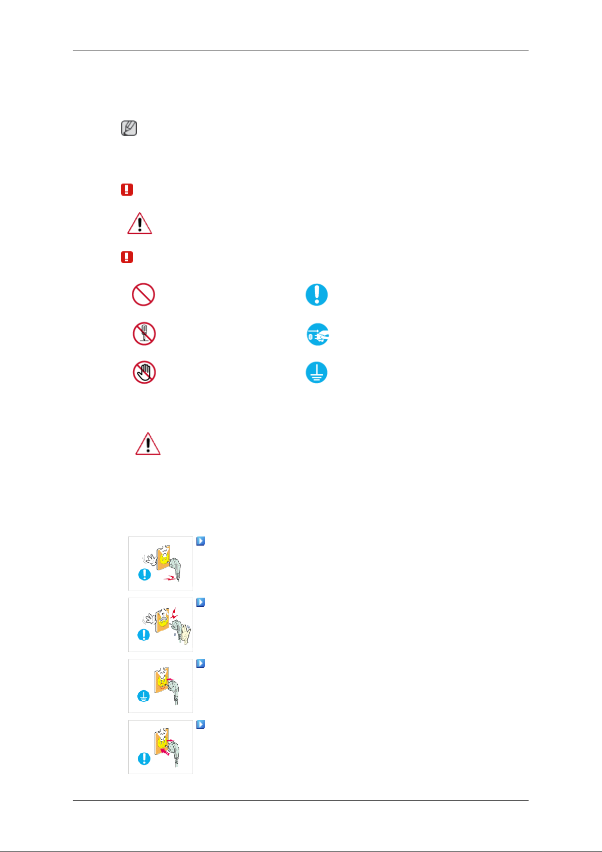
Do not use a damaged power cord or plug or a damaged or loose power
outlet.
• Otherwise, this may result in electric shock or fire.
Important to read and understand at all times
Disconnect the plug from the
outlet
Ground to prevent an electric
shock
Do not touch the power plug with wet hands when removing or plug-
ging the plug into the outlet.
• Otherwise, this may result in electric shock.
Make sure to connect the power cord to a grounded power outlet.
• Otherwise, it may result in electric shock or personal injury.
Ensure that the power plug is plugged into the power outlet firmly and
correctly.
• Otherwise, this may result in fire.
1
Page 3
Safety Instructions
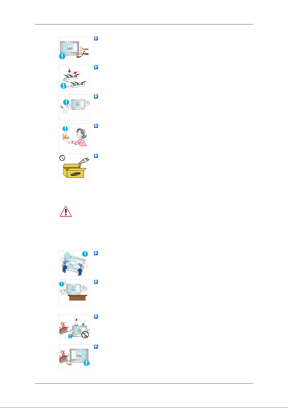
Do not forcefully bend or pull the power plug and do not place any
heavy material on it.
• Otherwise, this may result in fire.
Do not connect multiple appliances to the same power outlet.
• Otherwise, this may cause fire due to overheating.
Do not disconnect the power cord while using the product.
• Otherwise, this may result in damage to the product due to electric
shock.
To disconnect the apparatus from the mains, the plug must be pulled
out from the mains socket, therefore the mains plug shall be readily operable.
• This may cause electric shock or fire.
Use only the power cord provided by our company. Do not use the
provided power cord of another product.
Installation
• Otherwise, this may result in fire or electric shock.
Be sure to contact an authorized Service Center when installing your monitor in
a location with heavy dust, high or low temperatures, high humidity, and exposed
to chemical substances and where it operates for 24 hours such as at airports,
train stations etc.
Failure to do so may cause serious damage to your monitor.
Ensure that at least two persons lift and move the product.
• Otherwise, it may be dropped and cause personal injury, and/or dam-
age the product.
When installing the product in a cabinet or rack, make sure that the
front end of the bottom of the product does not project out.
• Otherwise, it may fall or cause personal injury.
• Use a cabinet or rack of a size appropriate to the product.
DO NOT PLACE CANDLES, MOSQUITO REPELLANT, CIGARETTES AND ANY HEATING APPLIANCES NEAR THE PRODUCT.
• Otherwise, this may result in fire.
Keep heating appliances as far away from the power cord or the product as possible.
• Otherwise, this may result in electric shock or fire.
2
Page 4
Safety Instructions
Do not install it in a badly ventilated location such as a bookcase or
closet.
• Otherwise, this may result in fire due to an increase in the internal
temperature.
When putting the product down, make sure to put it down softly.
• Otherwise, this may result in damage to the screen display.
Do not place the front of the product on the floor.
• Otherwise, this may result in damage to the screen display.
Ensure that an authorized installation company installs the wall mount.
• Otherwise, it may fall and cause personal injury.
• Make sure to install the specified wall mount.
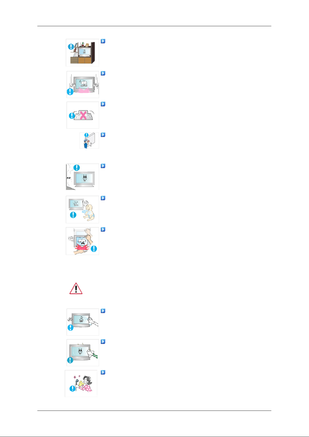
Install your product in a well ventilated location. Ensure that there is
a clearance of more than 10 cm from the wall.
Clean
• Otherwise, it may result in fire due to an increase in the internal tem-
perature.
Ensure that the packaging vinyl is kept away from children.
• Otherwise, it may result in serious harm (suffocation) if children play
with it.
If the height of your monitor is adjustable, do not place any object or
part of your body on the stand when lowering it.
• This may cause damage to the product or the person carrying it.
When cleaning the monitor case or the surface of the PDP screen, wipe with a
slightly moistened, soft fabric.
Do not spray cleaner directly onto the surface of the product.
• Otherwise, this may result in the discoloration and distortion of the
structure and the screen surface may peel off.
Clean the product using a soft cloth with a monitor cleaner only. If
you must use a cleaner other than the monitor cleaner, dilute it with water
at a ratio of 1:10.
When cleaning the power plug pins or dusting the power outlet, clean
it with a dry cloth.
• Otherwise, it may result in fire.
3
Page 5
Safety Instructions
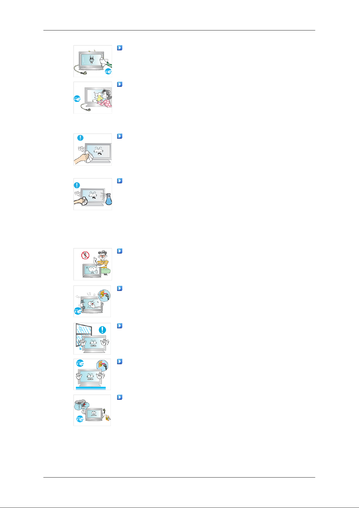
When cleaning the product, make sure to disconnect the power cord.
• Otherwise, it may result in electric shock or fire.
When cleaning the product, disconnect the power cord and clean it
softly with a dry cloth.
• (Do not use chemicals such as wax, benzene, alcohol, thinner, mos-
quito repellant, lubricant, or cleaner.) These may change the appearance of the product surface and peel off the indication labels on the
product.
Since the product housing is easily scratched, make sure to use the
specified cloth only.
• Use the specified cloth adding only a little water. As the product may
be scratched if there is any foreign material on the cloth, make sure
to shake it thoroughly before using it.
When cleaning the product, do not spray water directly onto the main
body of the product.
Others
• Ensure that water does not enter the product and that it is not wet.
• Otherwise, this may result in electric shock, fire or a malfunction.
The product is a high voltage product. Ensure that users do not disassemble, repair or modify the product themselves.
• Otherwise, this may result in electric shock or fire. If the product
needs to be repaired, contact a Service Center.
If there is a strange smell or a strange sound or smoke is coming from
the product, disconnect the power plug immediately and contact a Service
Center.
• Otherwise, this may result in electric shock or fire.
Do not place this product in a location exposed to moisture, dust,
smoke, water, or in a car.
• Otherwise, this may result in electric shock or fire.
When you drop the product or the case is broken, turn the power off
and disconnect the power cord. Contact a Service Center.
• Otherwise, this may result in electric shock or fire.
If thunder or lightening is occurring, do not touch the power cord or
antenna cable.
• Otherwise, this may result in electric shock or fire.
4
Page 6
Safety Instructions
Do not try to move the monitor by pulling only the wire or the signal
cable.
• Otherwise, it may fall and result in electric shock, damage to the
product or fire due to damage to the cable.
Do not lift or move the product back and forwards or right and left
while only holding the power cord or signal cables.
• Otherwise, it may fall and result in electric shock, damage to the
product or fire due to damage to the cable.
Make sure that the ventilating opening is not blocked by a table or
curtain.
• Otherwise, it may result in fire due to an increase in the internal tem-
perature.
Do not place any containers containing water, vases, flowerpots, medicines as well as any metal on the product.
• If water or a foreign material enters the product, disconnect the power
cord and contact a Service Center.
• This may result in a product malfunction, electric shock, or fire.
Do not use or keep combustible spray or flammable material near the
product.
• Otherwise, this may result in an explosion or fire.
Do not insert any metal, such as chopsticks, coins, pins and steel, or
flammable objects, such as matches or paper, inside the product (through
the ventilating openings, input and output terminals, etc).
• If water or foreign material enters the product, disconnect the power
cord and contact a Service Center.
• Otherwise, this may result in electric shock or fire.
When using a fixed screen for a long time, an afterimage or stain may
occur.
• If you are not using your product for a long period of time, put it into
sleep mode or use a moving screen saver.
Set a resolution and frequency appropriate to the product.
• Otherwise, your eyesight may be damaged.
When using headphones or earphones, do not turn the volume too high.
• Having the sound too loud may damage your hearing.
If you continually move closer to the product screen, your eyesight
may be failing.
5
Page 7
Safety Instructions
Take a rest for at least five (5) minutes after using the monitor for one
(1) hour.
This reduces the weariness of your eyes.
Do not install it in an unstable location such as an unstable rack or
uneven surface or a location exposed to vibrations.
• Otherwise, it may fall and cause personal injury and/or damage the
product.
• If you use the product in a location exposed to vibrations, it may
damage the product and result in fire.
When moving the product, turn the power off and disconnect the power
plug, antenna cable, and all the cables connected to the product.
• Otherwise, it may result in electric shock or fire.
Ensure that children do not hang onto the product or climb up onto the
product.
• The product may fall and cause personal injury or death.
If you do not use the product for a long period of time, disconnect the
power cord from the power outlet.
• Otherwise, this may result in overheating or fire due to dust, and may
result in fire due to electric shock or leakage.
Do not place any heavy items or toys or confectionery, such as cookies
etc. that may attract the attention of children and to the product.
• Your children may hang onto the product causing it to fall and this
may result in personal injury or death.
Be careful that children do not place the battery in their mouths when
removed from the remote control. Place the battery in a location that
children or infants cannot reach.
• If children have had the battery in their mouths, consult your doctor
immediately.
When replacing the battery, insert it with right polarity (+, -).
• Otherwise, the battery may become damaged or it may cause fire,
personal injury or damage due to leakage of the internal liquid.
Use only the specified standardized batteries, and do not use a new
battery and a used battery at the same time.
• Otherwise, the batteries may be damaged or cause fire, personal in-
jury or damage due to a leakage of the internal liquid.
The batteries (and rechargeable batteries) are not ordinary refuse and
must be returned for recycling purposes. The customer is responsible for
returning the used or rechargeable batteries for recycling.
• The customer can return used or rechargeable batteries to a nearby
public recycling center or to a store selling the same type of the battery
or rechargeable battery.
6
Page 8
Safety Instructions
Do not place the product in a location exposed to direct sunlight or
near any heat such as a fire or heater.
• This may reduce the lifetime of the product, and may result in fire.
Do not drop any objects onto the product or cause any impact to the
product.
• Otherwise, this may result in electric shock or fire.
Do not use a humidifier or kitchen table near the product.
• Otherwise, this may result in electric shock or fire.
When there is a gas leak, do not touch the product or the power plug
but ventilate immediately.
• If a spark occurs, it may cause an explosion or fire.
If the product has been turned on for a long time, the display panel
becomes hot. Do not touch it.
• Keep the small accessories in a location out of the reach of children.
Be careful when adjusting the angle of the product or the height of the
stand.
• This may result in personal injury as your hand or fingers may be-
come caught.
• Also, if you tilt the product too far, it may fall and cause personal
injury.
Do not install the product in a location low enough for children to
reach.
• Otherwise, it may fall and result in personal injury.
• Since the front part of the product is heavy, install the product on a
level and stable surface.
Do not put any heavy objects on the product.
• This may result in personal injury and/or damage to the product.
7
Page 9
Introduction
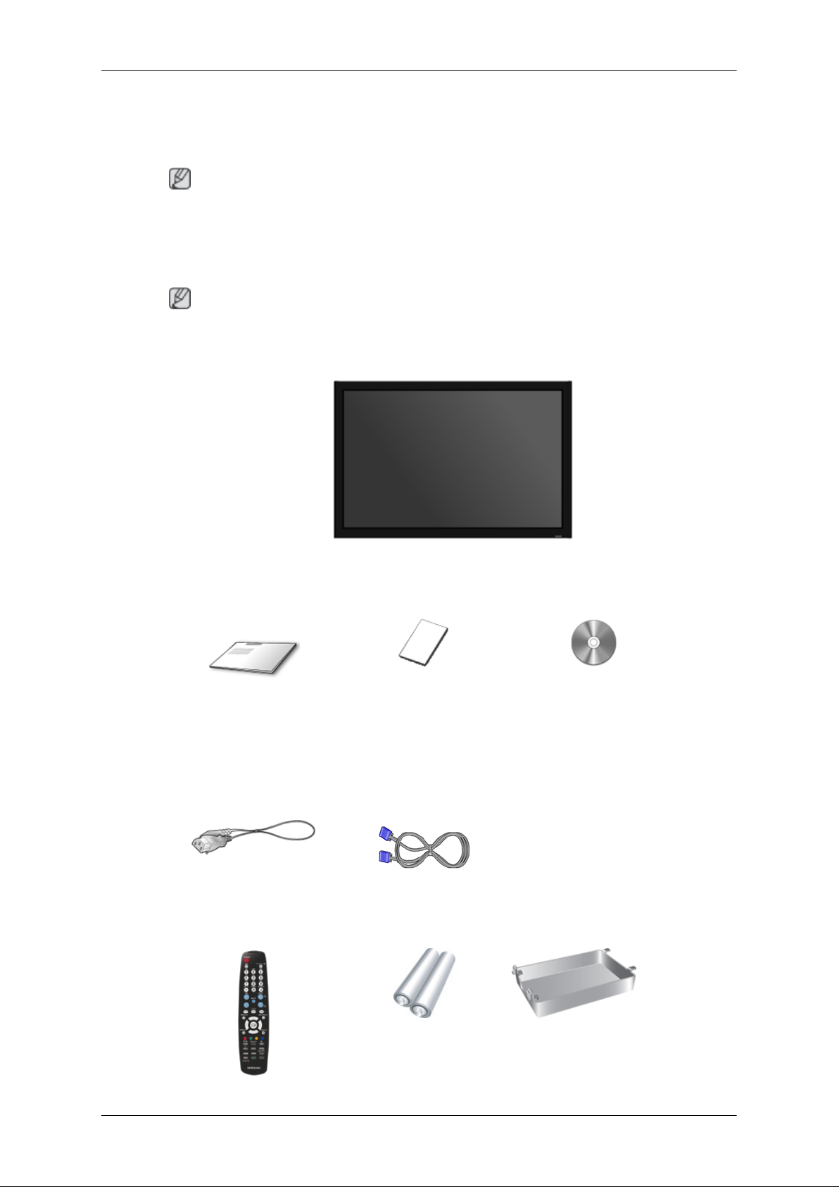
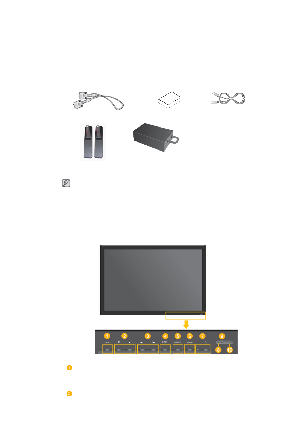
Package Contents
Note
Please make sure the following items are included with your LCD Display.
If any items are missing, contact your dealer.
Contact a local dealer to buy optional items.
Note
This stand is not for the Floor Standing Type.
Unpacking
Manuals
Quick Setup Guide Warranty Card
(Not available in all loca-
Cables
Power Cord D-Sub Cable
Others
LCD Display
User's Guide
tions)
8
Page 10
Introduction
Others
Remote Control Batteries (AAA X 2)
(Not available in all loca-
tions)
Sold separately
DVI Cable Wall Mount KIT LAN Cable
Semi Stand KIT TV tuner box
HDD Cover
Note
• You can purchase and connect a separate network box or TV tuner box. For information on how
to use these, refer to their respective user manuals.
• You can only connect one external box.
Your LCD Display
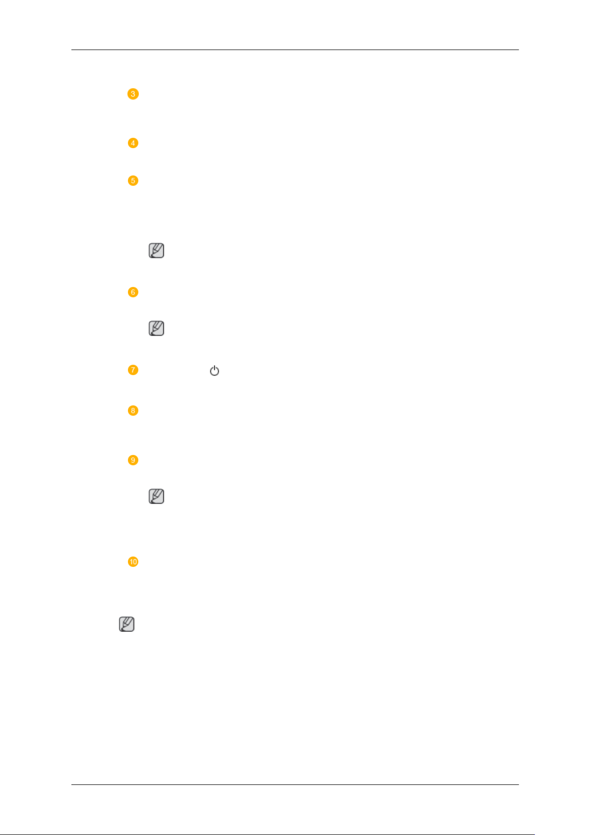
Front
MENU button [MENU]
Opens the on-screen menu and exits from the menu. Also use to exit the OSD menu
or return to the previous menu.
Navigate buttons (Up-Down buttons)
9
Page 11
Introduction
Moves from one menu item to another vertically or adjusts selected menu values.
Adjust buttons (Left-Right buttons) / Volume buttons
Moves from one menu item to another horizontally or adjusts selected menu values. When OSD is not on the screen, push the button to adjust volume.
ENTER button [ENTER]
Activates a highlighted menu item.
SOURCE button [SOURCE]
Switches from PC mode to Video mode. Changing the source is only allowed for
external devices that are connected to the LCD Display at the time.
[PC] → [DVI] → [AV] → [HDMI] → [MagicInfo]
Note
• The TV menu is available when a TV tuner box is installed.
D.MENU
Opens the on-screen D.MENU.
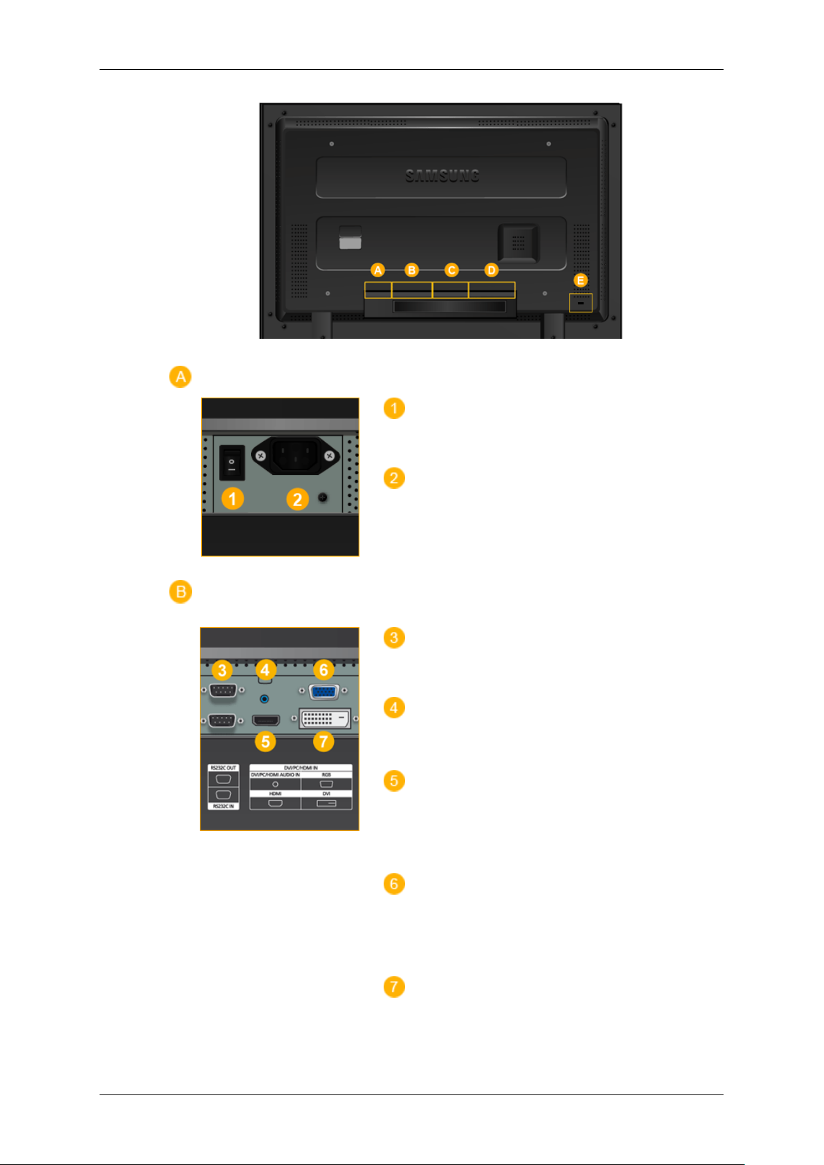
Rear
Note
• This is available when a TV tuner box is installed.
Power button [ ]
Use this button for turning the LCD Display on and off.
Brightness Sensor
The product's Brightness Sensor function automatically detects the surrounding
brightness using a brightness sensor and adjusts its brightness accordingly.
Power indicator
Shows PowerSaver mode by blinking green
Note
See PowerSaver described in the manual for further information regarding power
saving functions. For energy conservation, turn your LCD Display OFF when it
is not needed or when leaving it unattended for long periods.
Remote Control Sensor
Aim the remote control towards this spot on the LCD Display.
Note
For detailed information concerning cable connections, refer to Connecting Cables under Setup. The
LCD Display 's configuration at the back may vary slightly depending on the LCD Display model.
10
Page 12
Introduction
POWER S/W ON [ │ ] / OFF [O]
Switches the LCD Display On/Off.
POWER IN
The power cord plugs into the LCD Display and
the wall plug.
RS232C OUT/IN (RS232C Serial PORT)
MDC(Multiple Display Control) Program Port
DVI / PC / HDMI IN [DVI/PC/HDMI AUDIO
IN] (PC/DVI/HDMI Audio Connection Terminal
(Input))
DVI / PC / HDMI IN [HDMI]
Connect the HDMI terminal at the back of your
LCD Display to the HDMI terminal of your digital output device using a HDMI cable.
DVI / PC / HDMI IN [RGB](PC Video Connection Terminal)
Using a D-Sub Cable (15 pin D-Sub) - PC mode
(Analog PC)
DVI / PC / HDMI IN [DVI] (PC Video Connection Terminal)
Using a DVI Cable (DVI-D to DVI-D) - DVI
mode (Digital PC)
11
Page 13
Introduction
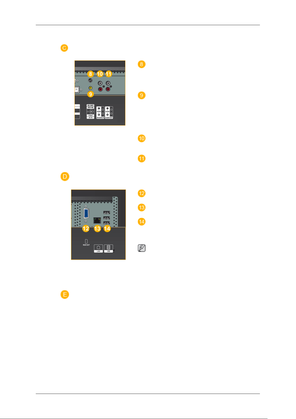
DC OUT [5V/1.5A]
Connect this to the POWER connector of a TV
tuner box or network box.
AV IN [VIDEO] (VIDEO Connection Terminal)
Connect the [ VIDEO ] terminal of your monitor
to the video output terminal of the external device
using a VIDEO cable.
AV AUDIO IN [L-AUDIO-R](LCD Display
Audio Connection Terminal (Input))
AV AUDIO OUT [L-AUDIO-R] (LCD Display Audio Connection Terminal (Output))
RGB OUT
LAN (LAN Connection Terminal)
USB(USB Connection Terminal)
Keyboard / Mouse, Mass Storage Device Com-
patible.
Note
The number of LCD Displays that can be connected to loopout may differ depending on the
cables, signal source etc. With cables where there
is no degradation or signal source, up to ten LCD
Displays can be connected.
12
Page 14
Introduction
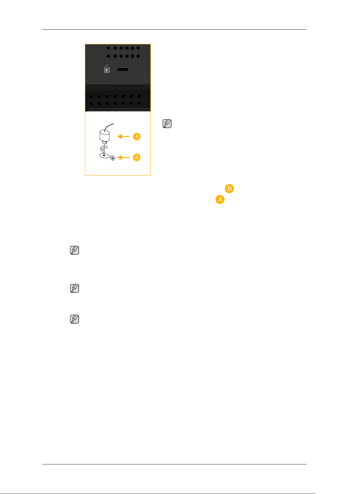
Kensington Lock
The Kensington Lock is a device used to physically fix the system when using it in a public
place. The locking device has to be purchased
separately. The appearance and locking method
may differ from the illustration depending on the
manufacturer. Refer to the manual provided with
the Kensington Lock for proper use. The locking
device has to be purchased separately.
Note
The location of the Kensington Lock may be different depending on its model.
Using the Anti-Theft Kensington Lock
1. Insert the locking device into the Kensington
slot on the Monitor and turn it in the
Note
See Connecting Cables for further information regarding cable connections.
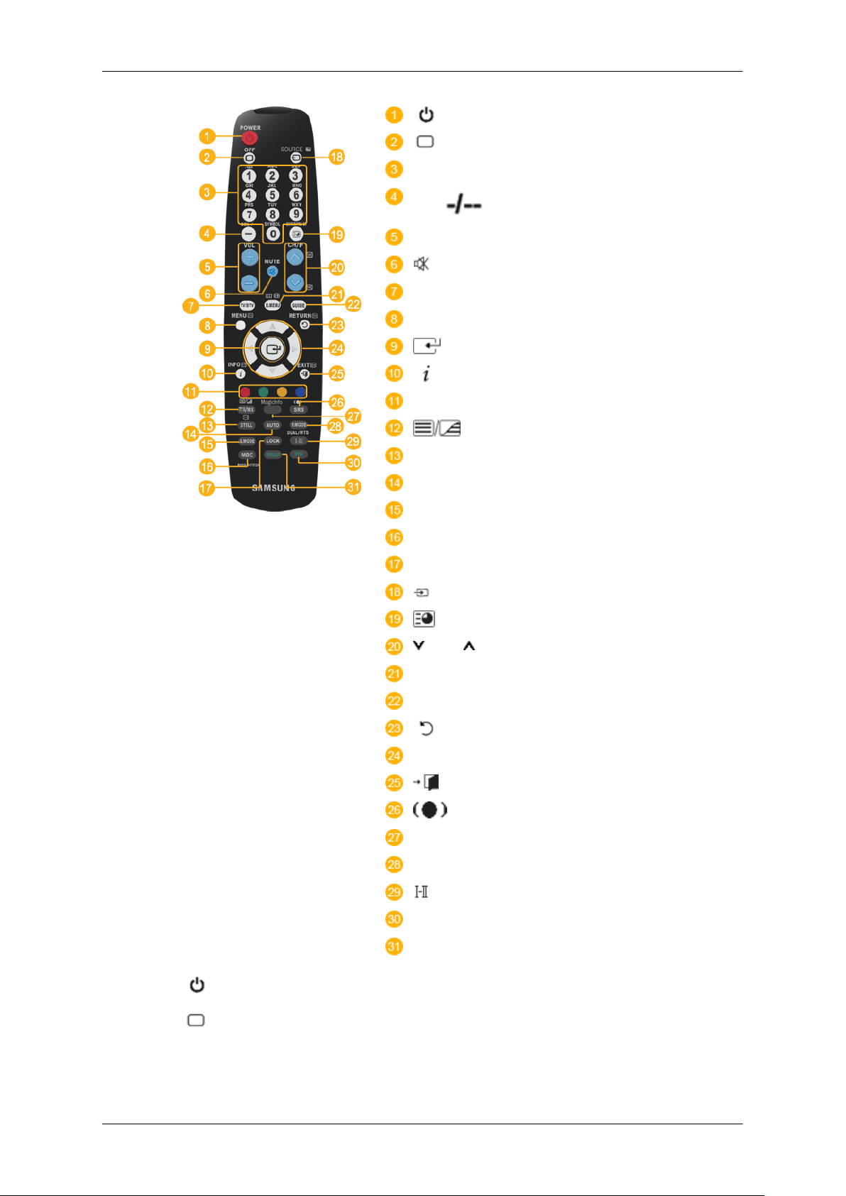
Remote Control
Note
The performance of the remote control may be affected by a TV or other electronic device operating
near the LCD Display , causing a malfunction due to interference with the frequency.
Note
The TV menu is available when a TV tuner box is installed.
locking direction .
2. Connect the Kensington Lock cable.
3. Fix the Kensington Lock to a desk or a heavy
stationary object.
13
Page 15
Introduction
POWER
OFF
Number Buttons
DEL button
+ VOL -
MUTE
TV/DTV
MENU
INFO
COLOR BUTTONS
TTX/MIX
STILL
AUTO
S.MODE
MDC
LOCK
SOURCE
ENTER/PRE-CH
CH/P
D.MENU
GUIDE
RETURN
Up-Down Left-Right buttons
EXIT
SRS
MagicInfo
P.MODE
DUAL/MTS
PIP
SWAP
1. POWER
2.
Off
3. Number Buttons Press to change the channel.
Turns the product On.
Turns the product Off.
14
Page 16

Introduction
The "-" button operates only for DTV. It is used to select MMS
4. DEL button
5. + VOL - Adjusts the audio volume.
(multi-channel) for a DTV.
6.
MUTE
7. TV/DTV Selects the TV and DTV mode directly.
8. MENU Opens the on-screen menu and exits from the menu or closes the
9.
10. INFO
11.COLOR BUTTONS Press to add or delete channels and to store channels to the favorite
12. TTX/MIX
13.STILL Press the button once to freeze the screen. Press it again to un-
Pauses (mutes) the audio output temporarily. This is displayed on
the lower left corner of the screen. The audio resumes if MUTE
or - VOL + is pressed in the Mute mode.
adjustment menu.
Activates a highlighted menu item.
Current picture information is displayed on the upper left corner
of the screen.
channel list in the “Channel List” menu.
TV channels provide written information services via teletext.
- Teletext Buttons
For more information > TTX / MIX
freeze.
14.AUTO Adjusts the screen display automatically in PC mode. By changing
the resolution in the control panel, auto function is performed.
15. S.MODE When pressing this button, the current mode is displayed at the
bottom centre of the screen. The LCD Display has a built-in high
fidelity stereo amplifier. Then press the button again to circle
through available preconfigured modes. ( Standard → Music
→ Movie → Speech → Custom )
16.MDC MDC Quick Launch Button.
17.LOCK Activates or deactivates all function keys on both the remote control and the LCD Display except for the Power and LOCK buttons.
18.
SOURCE
19. ENTER/PRE-CH
20. CH/P In TV mode, selects TV channels.
21.D.MENU DTV menu display
22.GUIDE Electronic Program Guide (EPG) display.
Press the button to change the input signal SOURCE.
Changing the SOURCE is only allowed for external devices that
are connected to the monitor at the time.
This button is used to return to the immediately previous channel.
23. RETURN
Returns to the previous menu.
15
Page 17

Introduction
24. Up-Down Left-Right but-
tons
25.
26. SRS
27.MagicInfo MagicInfo Quick Launch Button.
28. P.MODE When you press this button, current picture mode is displayed on
EXIT
Moves from one menu item to another horizontally, vertically or
adjusts selected menu values.
Exits from the menu screen.
Selects SRS TruSurround XT mode.
the lower center of the screen.
AV / HDMI / TV : P.MODE
The LCD Display has four automatic picture settings that are preset at the factory. Then push button again to circle through available preconfigured modes. ( Dynamic → Standard → Movie
→ Custom )
PC / DVI / MagicInfo: M/B (MagicBright)
MagicBright is a feature providing the optimum viewing environment depending on the contents of the image you are watching.
Then push button again to circle through available preconfigured
modes. (Entertain → Internet → Text → Custom )
29.
DUAL/MTS
30. PIP Every time you press the button, a PIP screen appears.
31.SWAP Swaps the contents of the PIP and main image. The image in the
DUAL-
STEREO/MONO, DUAL l / DUAL ll and MONO/NICAM
MONO/NICAM STEREO can be operated depending on the
broadcasting type by using the DUAL button on the remote control
while watching TV.
MTS-
You can select MTS (Multichannel Television Stereo) mode.
Audio Type MTS/S_Mode Default
FM Stereo Mono Mono Manual Change
Stereo
SAP
- This fuction does not work for this LCD Display.
PIP window will appear on the main screen, and the main screen
image will appear in the PIP window.
Mono ↔ Stereo
Mono ↔ SAP
Mono
Mechanical Layout
Mechanical Layout
- This fuction does not work for this LCD Display.
16
Page 18
Introduction
LCD Display Head
NETWORK MODEL SIZE
17
Page 19
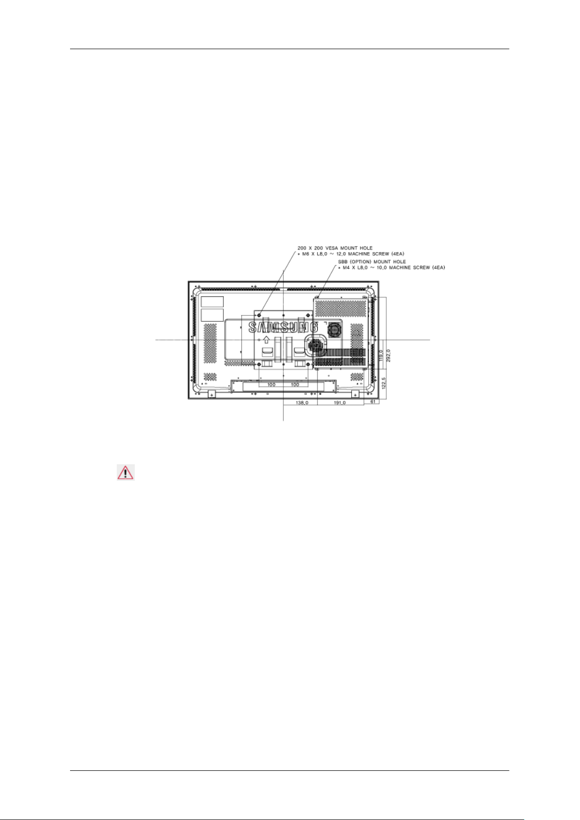
Installation VESA Bracket
• When installing VESA, make sure to comply with the international VESA standards.
• Purchasing VESA Bracket and Installation Information : Please contact your nearest SAMSUNG
Distributor to place an order. After your order is placed, installation professionals will visit you
and install the bracket.
• At least 2 persons are needed in order to move the LCD Display.
• SAMSUNG is not responsible for any product damage or any injury caused by installation at
customer's discretion.
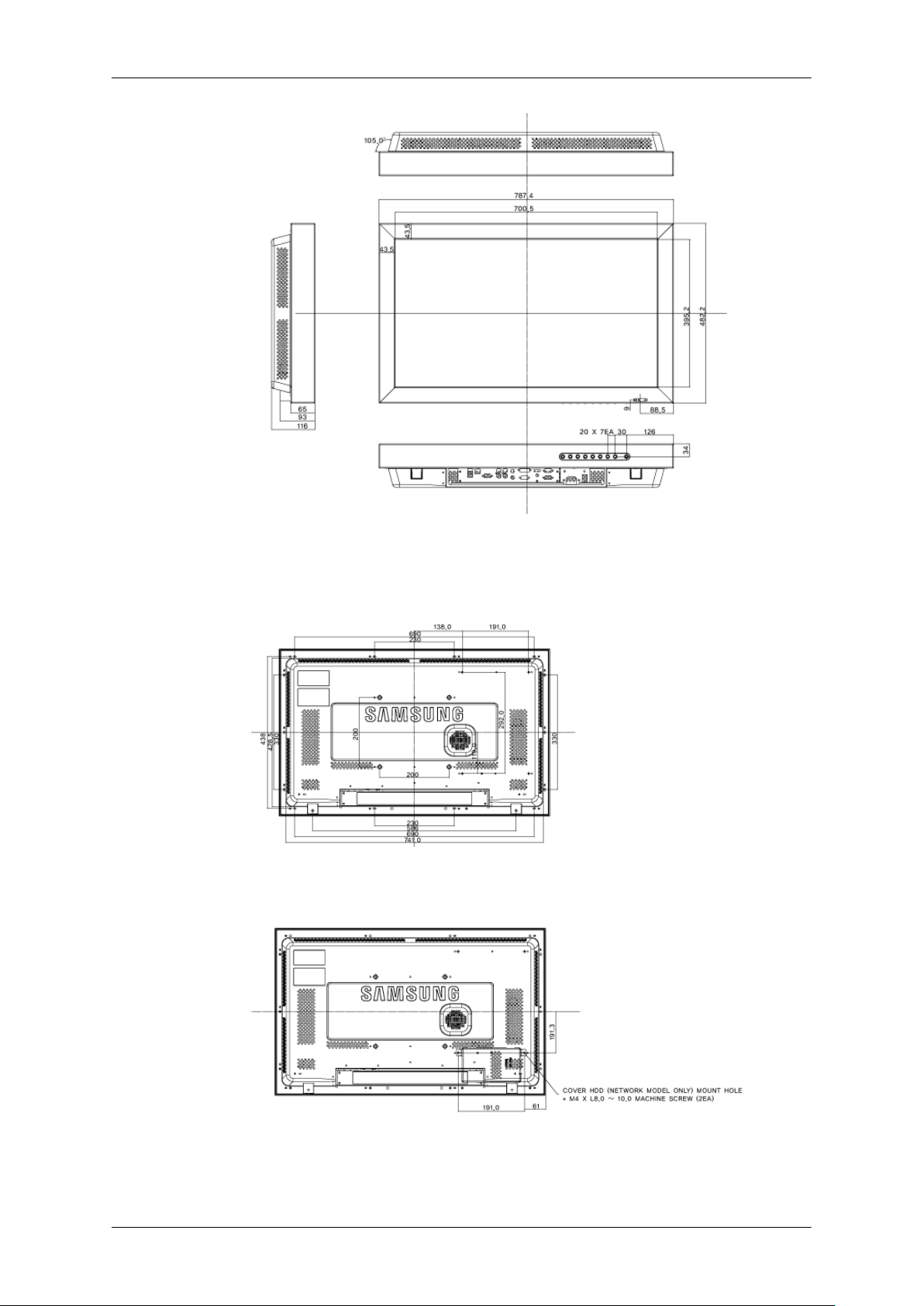
Dimensions
Introduction
Notice
For securing the bracket on a wall, use only machine screws of 6 mm diameter and 8 to 12 mm length.
Wall Bracket Installation
• Contact a technician for installing the wall bracket.
• SAMSUNG Electronics is not responsible for any damages to the product or harm to customers
when the installation is done by the customer.
• This product is for installing on cement walls. The product may not stay in place when installed
on plaster or wood.
Components
Only use the components and accessories shipped with the product.
18
Page 20

Introduction
Wall Bracket(1) Hinge(Left 1, Right1)Plastic
Wall Bracket Assembly
Note
There are two hinges(left and right). Use the correct one.
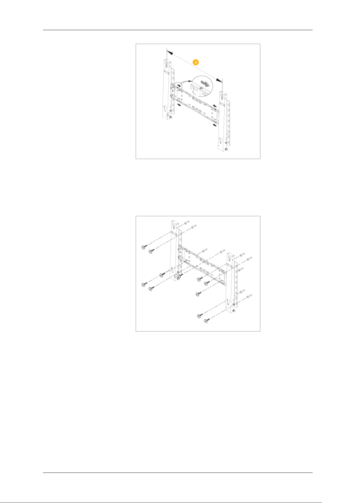
1. Insert and tighten the Captive Screw in the direction of the arrow.
When done, mount the wall bracket on the wall.
Hanger
(4)
Screw
(A)(11)
Screw(B)
(4)
Anchor
(11)
There are two hinges(left and right). Use the correct one.
A - Captive Screw
B - Wall Bracket
C - Hinge (Left)
D - Hinge (Right)
2. Before drilling into the wall, check if the length between the two locking holes at the back of the
product is correct.
If the length is too short or long, loosen all or some of the 4screws on the wall bracket to adjust
the length.
19
Page 21
Introduction
A - Length between the two locking holes
3. Check the installation diagram and mark the drill points on the wall. Use the 5.0 mm bit to drill
holes deeper than 35 mm. Fix each anchor in the corresponding hole. Match each of the brackets
and hinge holes to the corresponding anchor holes and insert and tighten the 11 screws A.
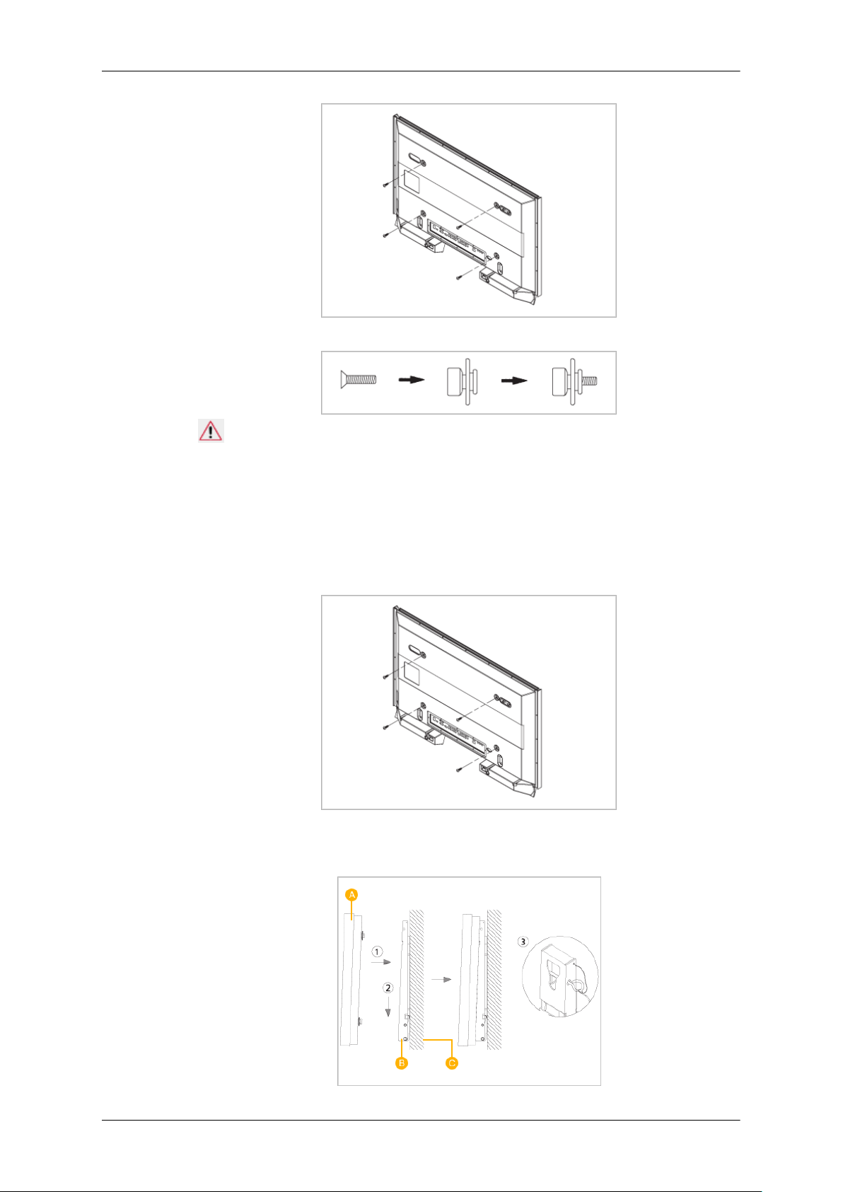
To mount the product on the wall bracket
The shape of the product may vary depending on the model. (The assemblies of the plastic hanger and
the screw are the same)
1. Remove the 4 screws on the back of the product.
20
Page 22
Introduction
2. Insert the screw B into the plastic hanger.
Notice
• Mount the product on the wall bracket and make sure it is properly fixed to the left and right
plastic hangers.
• Be careful when installing the product on the bracket as fingers can be caught in the holes.
• Make sure the wall bracket is securely fixed to the wall, or the product may not stay in place
after installation.
3. Tighten the 4 screws in step 2 (plastic hanger + screw B)to the rear holes of the product.
4. Remove safety pin (3) and insert the 4 product holders into the corresponding bracket holes (1).
Then place the product(2) so that it is firmly fixed to the bracket. Make sure to re-insert and tighten
the safety pin (3) to securely hold the product to the bracket.
21
Page 23

A - LCD Display
B - Wall Bracket
C - Wall
Wall Bracket Angle Adjustment
Adjust the bracket angle to -2° before installing it on the wall.
1. Fix the product to the wall bracket.
Introduction
2. Hold the product at the top in the center and pull it forward (direction of the arrow) to adjust the
angle.
Note
You can adjust the bracket angle between -2° and 15°.
Make sure to use the top center, and not the left or the right side of the product to adjust the angle.
22
Page 24
Connections
Connecting a Computer
Using a Power cord with Earth
• In the event of failure, the earth lead may cause electric shock. Make sure to
wire the earth lead in correctly, before connecting the AC power. When unwiring the earth lead, make sure to disconnect the AC power in advance.
Note
AV input devices such as DVD players, VCRs or camcorders as well as your computer can be connected
to the LCD Display. For detailed information on connecting AV input devices, refer to the contents
under Adjusting Your LCD Display.
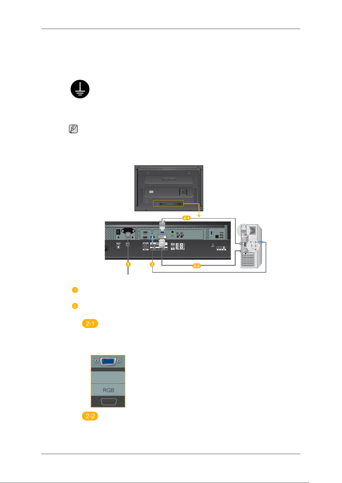
Connect the power cord for your LCD Display to the power port on the back of
the LCD Display. Turn on the power switch.
There are 2 ways to connect the D-sub to your LCD Display. Choose one of the
following:
Using the D-sub (Analog) connector on the video card.
• Connect the D-sub to the 15-pin, RGB port on the back of your LCD Display
and the 15 pin D-sub Port on the computer.
Using the DVI (Digital) connector on the video card.
• Connect the DVI Cable to the DVI port on the back of your LCD Display and
the DVI port on the computer.
23
Page 25
Connect the audio cable for your LCD Display to the audio port on the back of
your computer.
Note
• Turn on both your computer and the LCD Display.
• The DVI cable is optional.
• Contact a local SAMSUNG Electronics Service Center to buy optional items.
Connecting to Other devices
Connections
Using a Power cord with Earth
• In the event of failure, the earth lead may cause electric shock. Make sure to
wire the earth lead in correctly, before connecting the AC power. When unwiring the earth lead, make sure to disconnect the AC power in advance.
Note
AV input devices such as DVD players, VCRs or camcorders as well as your computer can be connected
to the LCD Display. For detailed information on connecting AV input devices, refer to the contents
under Adjusting Your LCD Display.
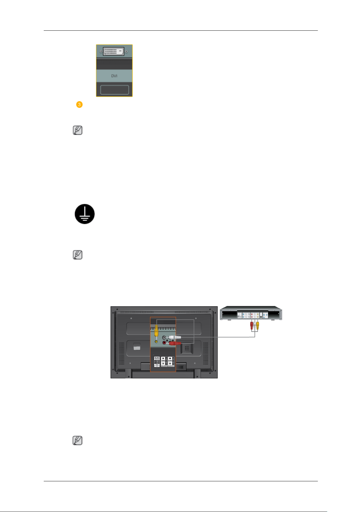
Connecting AV Devices
1. Connect the port of the DVD, VCR (DVD / DTV Set-Top Box) to the [R-AUDIO-L] port of the
LCD Display.
2. Then, start the DVD, VCR or Camcorders with a DVD disc or tape inserted.
3. Select AV using the SOURCE .
Note
The LCD Display has AV connection terminals to connect AV input devices like DVDs, VCRs or
Camcorders. You may enjoy AV signals as long as the LCD Display is turned on.
24
Page 26
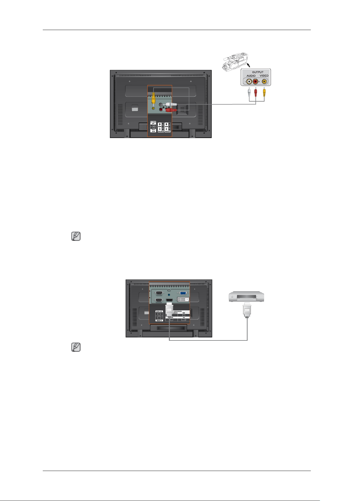
Connecting to a Camcorder
1. Locate the AV output jacks on the camcorder. They are usually found on the side or back of the
camcorder. Connect a set of audio cables between the AUDIO OUTPUT jacks on the camcorder
and the AV AUDIO IN [L-AUDIO-R] on the LCD Display .
2. Connect a video cable between the VIDEO OUTPUT jack on the camcorder and the AV IN
[VIDEO] on the LCD Display .
Connections
3. Select AV for the Camcorder connection using the Source button on the front of the LCD Display
or on the remote control.
4. Then, start the Camcorders with a tape inserted.
Note
The audio-video cables shown here are usually included with a Camcorder. (If not, check your local
electronics store.) If your camcorder is stereo, you need to connect a set of two cables.
Connecting Using a HDMI Cable
Note
• Input devices such as digital DVD are connected to the HDMI terminal of the LCD Display using
the HDMI cable.
• You cannot connect a PC to the HDMI terminal.
25
Page 27
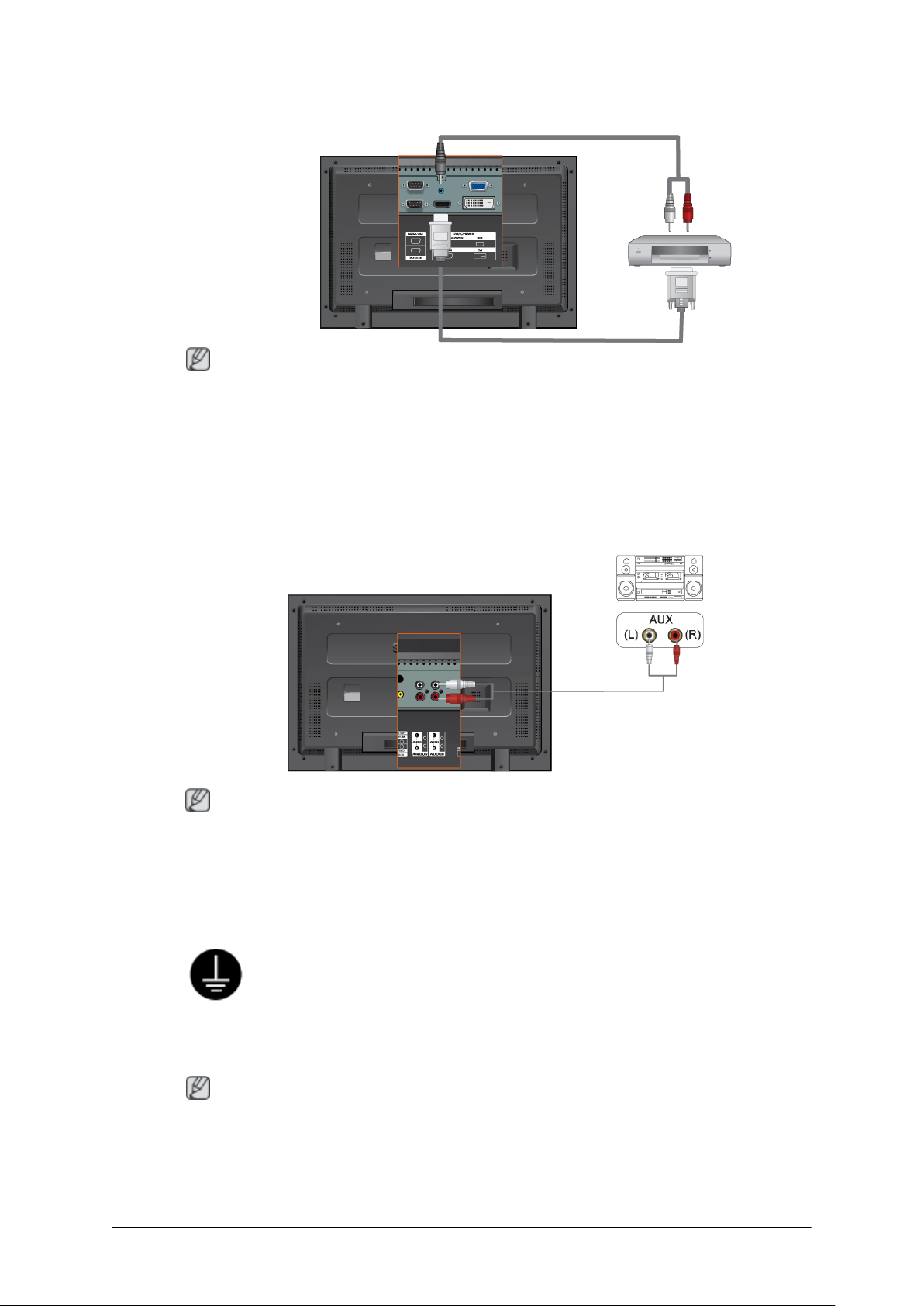
Connections
Connecting Using a DVI to HDMI Cable
Note
• Connect the DVI output terminal of a digital output device to the HDMI terminal of the LCD
Display using a DVI to HDMI cable.
• Connect the red and white jacks of an RCA to stereo (for PC) cable to the same colored audio
output terminals of the digital output device, and connect the opposite jack to the DVI / PC / HDMI
AUDIO IN terminal of the LCD Display.
Connecting to an Audio System
Note
• Connect a set of audio cables between the AUX L, R jacks on the AUDIO SYSTEM and AUDIO
OUT [L-AUDIO-R] on LCD Display.
Connecting a LAN Cable
Using a Power cord with Earth
• In the event of failure, the earth lead may cause electric shock. Make sure to
wire the earth lead in correctly, before connecting the AC power. When unwiring the earth lead, make sure to disconnect the AC power in advance.
Note
AV input devices such as DVD players, VCRs or camcorders as well as your computer can be connected
to the LCD Display. For detailed information on connecting AV input devices, refer to the contents
under Adjusting Your LCD Display.
26
Page 28
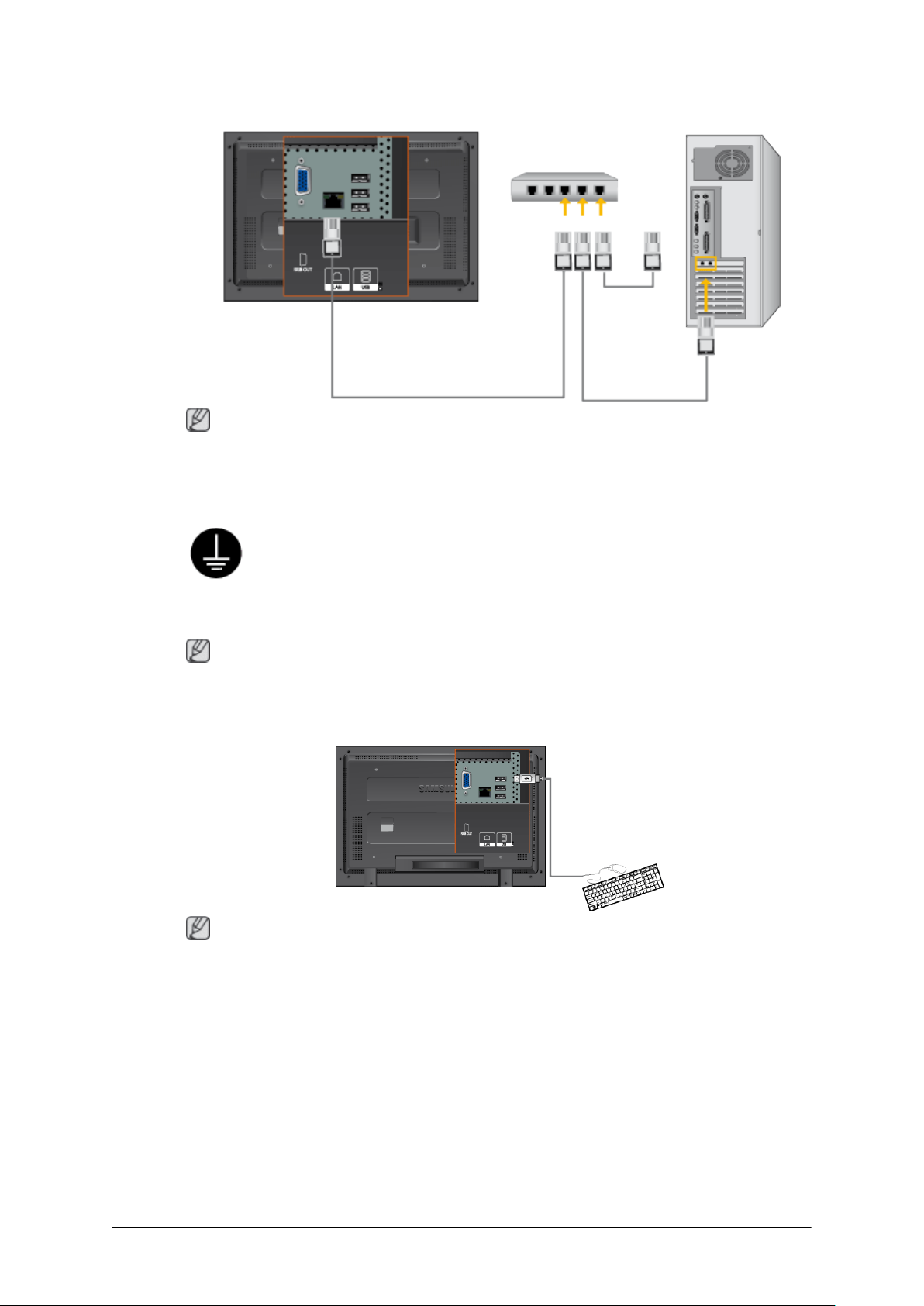
Note
Connect the LAN cable.
Connecting a USB device
Connections
Using a Power cord with Earth
• In the event of failure, the earth lead may cause electric shock. Make sure to
wire the earth lead in correctly, before connecting the AC power. When unwiring the earth lead, make sure to disconnect the AC power in advance.
Note
AV input devices such as DVD players, VCRs or camcorders as well as your computer can be connected
to the LCD Display. For detailed information on connecting AV input devices, refer to the contents
under Adjusting Your LCD Display.
Note
You can connect USB devices such as a mouse or keyboard.
27
Page 29
Using the Software
Monitor Driver
Note
When prompted by the operating system for the monitor driver, insert the CD-ROM
included with this monitor. Driver installation is slightly different from one operating
system to another. Follow the directions appropriate for the operating system you
have.
Prepare a blank disk and download the driver program file at the Internet web site
shown here.
Internet web site :
http://www.samsung.com/ (Worldwide)
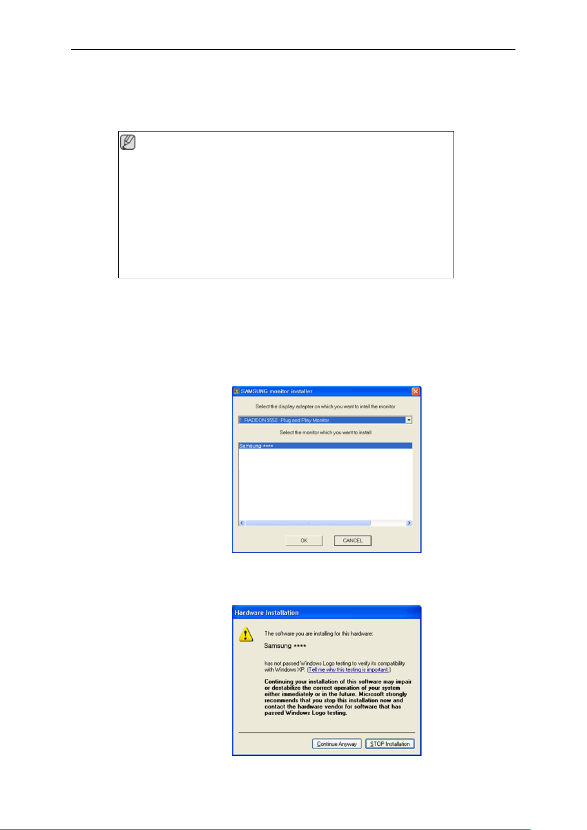
Installing the Monitor Driver (Automatic)
1. Insert CD into the CD-ROM drive.
2. Click "Windows".
3. Choose your monitor model in the model list, then click the "OK" button.
4. If you can see following message window, then click the "Continue Anyway" button. Then click
"OK" button (Microsoft® Windows® XP/2000 Operating System).
28
Page 30
Using the Software
Note
This monitor driver is under certifying MS logo, and this installation doesn't damage your system.
The certified driver will be posted on Samsung Monitor homepage.
http://www.samsung.com/
Installing the Monitor Driver (Manual)
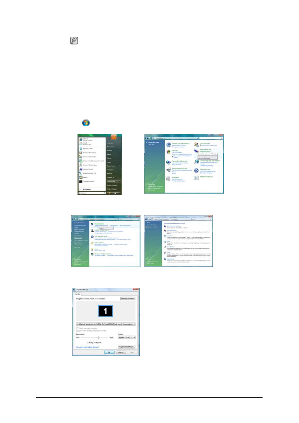
Microsoft® Windows Vista™‚ Operating System
1. Insert your Manual CD into your CD-ROM drive.
2.
Click
(Start) and "Control Panel". Then, double-click on "Appearance and Personalization".
3. Click "Personalization" and then "Display Settings".
4. Click "Advanced Settings...".
5. Click "Properties" in the "Monitor" tab. If the "Properties" button is deactivated, it means the
configuration for your monitor is completed. The monitor can be used as is.
If the message "Windows needs..." is displayed, as shown in the figure below, click "Continue".
29
Page 31

Using the Software
Note
This monitor driver is under certifying MS logo, and this installation doesn't damage your system.
The certified driver will be posted on Samsung Monitor homepage.
6. Click "Update Driver..." in the "Driver" tab.
7. Check the "Browse my computer for driver software" checkbox and click "Let me pick from a
list of device drivers on my computer".
8. Click "Have Disk...” and select the folder (for example, D:\Drive) where the driver setup file is
located, and click "OK".
30
Page 32

Using the Software
9. Select the model that matches your monitor from the list of monitor models on the screen, and
click "Next".
10.
Click "Close" → "Close" → "OK" → "OK" on the following screens displayed in sequence.
Microsoft® Windows® XP Operating System
31
Page 33

Using the Software
1. Insert CD into the CD-ROM drive.
2.
Click "Start" → "Control Panel" then click the "Appearance and Themes" icon.
3. Click "Display" icon and choose the "Settings" tab then click "Advanced...".
4. Click the "Properties" button on the "Monitor" tab and select "Driver" tab.
5. Click "Update Driver..." and select "Install from a list or..." then click "Next" button.
6. Select "Don't search, I will..." then click "Next" and then click "Have disk".
32
Page 34

Using the Software
7. Click the "Browse" button then choose A:(D:\Driver) and choose your monitor model in the model
list and click the "Next" button.
8. If you can see following message window, then click the "Continue Anyway" button. Then click
"OK" button.
Note
This monitor driver is under certifying MS logo, and this installation doesn't damage your system.
The certified driver will be posted on Samsung Monitor homepage.
http://www.samsung.com/
9. Click the "Close" button then click "OK" button continually.
33
Page 35

Using the Software
10. Monitor driver installation is completed.
Microsoft® Windows® 2000 Operating System
When you can see "Digital Signature Not Found" on your monitor, follow these steps.
1. Choose "OK" button on the "Insert disk" window.
2. Click the "Browse" button on the "File Needed" window.
3. Choose A:(D:\Driver) then click the "Open" button and then click "OK" button.
How to install
1. Click "Start", "Setting", "Control Panel".
2. Double click the "Display" icon.
3. Select the "Settings" tab and click "Advanced Properties" button.
4. Choose "Monitor".
Case1 : If the "Properties" button is inactive, it means your monitor is properly configured. Please
stop installation
Case2 : If the "Properties" button is active, click the "Properties" button then follow next steps
continually.
5. Click "Driver" and then click on "Update Driver..." then click on the "Next" button.
6. Choose "Display a list of the known drivers for this device so that I can choose a specific driver"
then click "Next" and then click "Have disk".
7. Click the "Browse" button then choose A:(D:\Driver).
8. Click the "Open" button, then click "OK" button.
9. Choose your monitor model and click the "Next" button then click "Next" button.
10. Click the "Finish" button then the "Close" button.
If you can see the "Digital Signature Not Found" window then click the "Yes" button. And click
the "Finish" button then the "Close" button.
Microsoft® Windows® Millennium Operating System
1. Click "Start", "Setting", "Control Panel".
2. Double click the "Display" icon.
3. Select the "Settings" tab and click "Advanced Properties" button.
34
Page 36

Using the Software
4. Select the "Monitor" tab.
5. Click the "Change" button in the "Monitor Type" area.
6. Choose "Specify the location of the driver".
7. Choose "Display a list of all the driver in a specific location..." then click "Next" button.
8. Click the "Have Disk" button.
9. Specify A:\(D:\driver) then click "OK" button.
10. Select "Show all devices" and choose the monitor that corresponds to the one you connected to
your computer and click "OK".
11. Continue choosing "Close" button and "OK" button until you close the Display Properties dialogue box.
Microsoft® Windows® NT Operating System
1. Click "Start", "Settings", "Control Panel", and then double-click "Display" icon.
2. In Display Registration Information window, click Settings Tab and then click "All Display
Modes".
3. Select a mode that you wish to use (Resolution, Number of colors and Vertical frequency) and
then click "OK".
4. Click "Apply" button if you see the screen working normally after clicking "Test". If the screen
is not normal, change to a different mode (lower mode of resolution, colors or frequency).
Note
If there is no Mode at All Display Modes, select the level of resolution and vertical frequency by
referring to the Preset Timing Modes in the user guide.
Linux Operating System
To execute X-Window, you need to make the X86Config file, which is a type of system setting file.
1. Press "Enter" at the first and the second screen after executing the X86Config file.
2. The third screen is for setting your mouse.
3. Set a mouse for your computer.
4. The next screen is for selecting a keyboard.
5. Set a Keyboard for your computer.
6. The next screen is for setting your monitor.
7. First of all, set a horizontal frequency for your monitor. (You can enter the frequency directly.)
8. Set a vertical frequency for your monitor. (You can enter the frequency directly.)
9. Enter the model name of your monitor. This information will not affect the actual execution of
X-Window.
10. You have finished setting up your monitor. Execute X-Window after setting other requested
hardware.
35
Page 37

IRTOUCH
IRTouch Screen Control Panel
Double click the mark on the tabletop (as the following indication), or follow "Start" -> "All programs"
-> "IRTouchSystems", and then click "IR TouchScreen Control Panel" and go to the Control Panel of
the touchscreen as following.
Using the Software
General Control Panel menu
1. The control panel provides adjustment and configuration with USB and IR touchscreen of serial
port and supports compatibility of multi-touchscreens at the same PC. This window shows the
basic information of the touchscreen and calibration. If several touchscreens are mounted on the
PC and status is set "multi-screens display", user may use the button [Select Monitor] and must
choose monitor related to each touchscreen before calibration, otherwise the touchscreen won't
work. The setting of multi-touchscreens at the same PC comprising of Steps: the butt mark will
appear on the center of each monitor screen in master slave sequence operated by program after
user clicks "Select Monitor". If does so, use may click the center of the butt mark so as to acknowledge the mounted-touchscreen. If there is no information of touchscreen on the monitor,
user is required to press "Esc" or wait for 15 seconds, then program will pass the current the setting
of touchscreen and continue automatically the next one; Double click the setting of touchscreen
in the list. User may select the monitor related to each IR touchscreen and click "OK" representing
the save and exit after the select-dialog box pops up. Finishing the above operations, program
will show the number of monitor relevant to each touchscreen in the list of "Monitor".
36
Page 38

Using the Software
2. Select the touchscreen you want in the list and Click [Calibrate]. After calibration, the item "Calibrated" will show "Yes".
Calibration compromising of steps: select a touchscreen in the information list, then click "calibrate"
button when the calibration window shows up. Calibration is done by clicking on 4 calibration points
so that user only clicks the center of the bull's-eye in sequence. If failing to hit the bull's eye, user may
move the pointer or fingers to the center of it again and lift based on the utilization of Click on Release
when calibration. Press 'Esc" button to exit calibration. After calibration the "recalibrate", "OK", "cancel" buttons will show up. "ReCalibrate" means recalibration; "OK" means saving and exit; "Cancel"
means exit without saving.
37
Page 39

Modes Setting
Using the Software
1. Click on touch
Mouse single click event happens immediately at the point when the finger contact the
touchscreen, not for dragging objects. In this mode the touchscreen responds fastest, it's usually
used for big button applications.
2. Click on Release
Mouse click event happens at the point where the finger leaves touchscreen; in this mode the
finger moving position is followed by eyes and precisely controlled, therefore it's suitable for
small buttons or hyperlink of web pages, such as POS, WEB applications.
3. Mouse Emulation
This is the default mode. Full emulation of mouse functions including left-button click, moving,
lifting, and dragging; if writing, drawing, or dragging map are required, this mode is well suitable
to the above application.
4. Enable Touch
Enable(default)/disable touchscreen;
5. Hide Cursor
Hide cursor without closedown of the mouse function; because Mouse cursor is not used in some
applications but always is applied to such filed as big button, playing animation, or children
education in "Click On Touch" mode.
6. Send Right Click
To enable right-click function(default). Click and press on any area on the screen for two seconds,
the right-click pop-up menu will show up. Right-click is only available in Mouse Emulation mode.
User may adjust the number of “delay” in “Right Click Settings” if finding the pop-up time is
38
Page 40

Using the Software
either fast or slow. Notice: the higher the value, the slower the pop-up time. "Delay" unit is
"millisecond". The "area" is used for adjusting the jitter-range of the touch surface within limit
of error (unit: pixel). The higher the value, the wider the jitter-range. Right Click menu will pop
up so long as the finger contacts the screen for a while within the range.
7. Enable Double Click
Same as the function of Mouse Double Click. Double click on the same setting area of objects in
a short time. The "Double Click Settings" property can be set so as to get the best performance
on Double Click. "Speed" unit is "millisecond". The higher the value, the longer the effective
time interval between the double clicks raising the function of Double Click. "Area" is used for
either amplifying or reducing the Double Click area. The higher the value (unit: pixel), the more
sensitive the response of Double Click. Double-click should be utilized in the applications such
as "Click on touch", "Click on Release", "Mouse Emulation".
8. Enable Delay Touch
After this function is enabled, high speed touch or scratch on the screen becomes ineffective. It
is the very effective for touch to maintain steadily for a time in specified area. This function is
for banking and industrial control applications, such as ATM, Switches of industrial equipment
and used in both Click on touch and Click on Release modes. The "Delay Touch Setting" properties can be set selectively. The higher the value (unit:millisecond), the longer the touch-delay
time; "area" is utilized to regulate the effective area in which finger maintains on the touch plane.
The higher the value (unit: pixel), the wider the effective area.
9. Prevent System to Standby
Unable (default); this function may prevent System from Standby. When the IR touchscreen is
provided with serial ports as a simple output device, the function may enable recovery out of the
state of automatic system standby.
10. Drag Delay
The function show the amount of millisecond "Drag Delay" will take to be enabled after you click
that. Drag Delay may be adjusted to the correct value if the object can not be precisely selected
or if jitter happens to cursor when you touch. The unit is millisecond.
11. False touch rejection
The snow and rain drop will be mistakenly a single touch. So the function of "False touch rejec-
tion" may be selected in driver to avoid the above error without the normal manipulation. The
function of "Enable Delay Touch" will do the work to prevent the false touch. Instructions see
Attachment : Setting of touchscreen in strong light, rain and snow condition.
Serial port Settings
1. Installation of the driver of serial port finished, choose "start" - "All Programs" - "IRTOUCHSYSTEMS" - "Serial Port Settings". In the list show both the name of IR touch device installed
and the number of the serial ports. You may choose [Install] when some serial ports are available
or choose [Remove] to uninstall the driver if you don't want to use the touchscreen.
39
Page 41

Using the Software
2. Click [Change Port] to set and change setting of the selected Serial Port.
Attachment
The general setting of touchscreen
Select "Mouse Emulation" mode, then choose "Enable Touch" Send Right ClickEnable DoubleClick.
In general functions of Enable Delay Touch and False touch rejection may not selected to avoidslowing
the touch response. It is proved null if you quickly click or drag the touch point.
40
Page 42

Using the Software
Installment
1. Send Right Click : To enable right-click function (default). Click and press on any area on the
screen for two second, the right-click menu will pop-up. Right-click is only available in Mouse
Emulation mode. The “Delay” value is 1000(1second); The “Area” value is set to 32px at optimum.
2. Enable Double Click : Same as the function of Mouse Double Click. Double click on the same
setting area of objects in a short time may open up the object. "Speed" unit is at 500 to 550. "Area"
unit is 32px.
3. Drag Delay : The function show the amount of millisecond "Drag Delay" will take to be enabled
after you click that. Drag Delay may be adjuste d to the correct value if theobject can not be
precisely selected or if jitter happens to cursor when you touch. The unit is millisecond.
Setting of touchscreen in strong light, rain and snow condition
The snow and rain drop will be mistakenly a single touch. So the function of “False touch rejection”
maybe selected in driver to avoid the above error without the normal manipulation. The function of
“EnableDelay Touch” will do the work to prevent the false touch.
41
Page 43

Using the Software
Specification
1. Each value should be gradually set in "Delay Touch Settings" after fulfillment of "Enable Delay
Touch". "Delay" is set to 40 and "Area" to 16.
2. Enter count : It means how many times you click to approach the setting value within 3 seconds.
Then driver will install the function of "False touch rejection" where quick click or scratch will
be considered void except the touch point on the active area for quite a while.
3. Leave count : "False touch rejection" is no longer effective when the click times within 5 seconds
is less than the setting number.
42
Page 44

Introduction
A Multiple Display Control (MDC) is an application a llowing various displays to be easily and simultaneously
operated on a PC. RS-232C, a standard of serial communication, is used for the communication between a PC and
a display. Therefore, a serial cable should be connected between the serial po rt on a PC and the serial port o n a
display.
Main Screen
Click Start > Program > Samsung > MDC System to start the program.
Select a set to see the volume of the selected set within the slider.
Page 45

Main Icons Select Button
Remocon Info Grid
Safet y L o ck Display Selection
Port Selection Control Tools
1. Use the main icons to switch into each screen.
2. Allows you to enable or disable the remote contro l si gnal receiving function of the display unit.
3. Set the Saf ety Lock function.
When setting th e Lock function, you can only operate power a nd lock buttons on the remote control and set.
4. The setting for the PC Serial Port can change. The original value is COM1.
5. Click Select all or Clear to select or clear all displa ys.
6. Use Grid to view brief inf ormation on selected display.
7. Select a display from Dis play Selection.
8. Use Control Tools to c o ntrol displays.
<Note> The remote control Enable/Disable function operates whether or not the power is On/Off, and this
applies to all displays connected to the MDC. However , re gardless of the status at the time the MDC is
shut down, the remo te co nt ro l s ignal receiving function of all dis plays is initialized to Enabl e whe n the
MDC is closed.
Port Se lection
Page 46

1. The Multiple Dis play Control is originally set to COM1.
2. If any port other than COM1 is used, COM1 through COM4 can be selected in the Port Selection Menu.
3. If the exact port na me th at is connected to the LCD Display using a serial cable is not selected, communication will
be unavail abl e.
4. The selected port is stored in the prog ram and used for t he next program a s well.
Power Con trol
1. Click Po wer Control of the main ico ns and the Power Control screen appea rs.
Page 47

Info Grid shows some basic information necessary to Power Control.
1) (Power Status)
2) Input
3) Image Size
4) On Timer
5) Off Timer
2. Use the Select All bu tton or Check Box to choose a display to control.
Power Control allo ws controlling some of the functions o f the selected display.
1)
Power On/Off
Page 48

-
T
(
(
urns the power of th e s el e cted display On/Off.
2) Volume
- Controls the volume lev el of the selected display.
It receives the volume value of the selected display from t he sets and displays it in the slider.
When you cancel the s ele ction or choose Select All, the value returns to the default value 10)
3)
(Mute On/Off)
- Turns on/off the Mute function of the selected display.
When selecting one set at a time, tu rn on the Mute f unction for the selected set.
The Mute f unction is disa bled automatically when you adjust t he volume level.
The value s ret ur n to th e de f a ul t s et tings when you undo the selections or choose "Select All".)
The Power Control feature is available for all displays.
The Volu me Control and Mute features are available only for the displays who se power statu s is ON.
Input Source
1. Cl ic k I n put Source of the main ic o ns an d the Input So u rce cont rol screen appear s .
Click Select All or use C heck Box to select a display to cont ro l.
• TV Mode
• PC Mode
Page 49

Info Grid shows some basic information necessary to Input Source Control.
g
g
g
V
g
T
g
1) PC
- Changes the Input Source of the selected display to PC.
2) BNC
- Changes the Input Source of the selected display to BNC.
3) DVI
- Changes the Input Source of the selected display to DVI.
4) TV
-Chan
es the Input Source of the selected display to TV.
5) DTV
-Chan
es the Input Source of the selected display to DTV.
6) AV
es the Input Source of the selected display to AV.
-Chan
7) S-Video
- Changes the Input Source of the selected display to S-
8) Component
-Chan
es the Input Source of the selected display to Component.
9) MagicInfo
-
he Input source of MagicInfo works only on MagicInfo model.
10) HDMI
-Chan
es the Input Source of the selected display to HDMI.
11) Channel
- Channel arrow appears when the Input Source is TV.
TV Source can be selected only in products with TV and controlling channels is allowed only when
Input Source is TV.
The Input Source Control feature is available only for the displays whose power status is ON.
ideo.
Image Size
PC, BN C, DVI
1. Click Image Size of the main icons and the Image Size control screen appears.
Page 50

Info Grid shows some basic information necessary to Image Size Control.
1)
( Power Status)
- Shows the p o w er s tatus of the current display.
2) Imag e Si ze
- Shows the current Image Size of the display in use.
3) Input
- Shows the current Input Source of th e display in use.
4) Info Grid dis plays only the displays whose Inp ut Source is PC, BNC, DVI.
5) PC So urce - When you cl ick Image Size, the PC Source tab fi rs t appear.
- The Image Size Control button controls Image Size available for PC, BNC, DVI.
6) Video Source
- Clic k th e Vi d eo Source tab to control Ima g e Si ze f o r re spectiv e Inp u t So u rc e.
The Input source of MagicInfo works only on MagicInfo model.
The Input source of TV works only on TV model.
Image Size Control is available only for the displays for which power status is ON.
Image Size
TV, AV, S-Video, Component, DVI(HDCP), HDMI, DTV
1. Click Image Size of the main icons and the Image Size control screen appears.
Page 51

Info Grid shows some basic information necessary to Image Size Control.
1) Click the Video Source tab to adjust Image Size for TV, AV, S-Video, Component, DVI(HDCP), HDMI, DTV.
Click Select All or use C heck Box to select a display to cont ro l.
2) Info Grid displays only the display having TV, AV, S-Video, Component or DVI(HDCP) as input source.
3) Switch Ima ge Size of the selected display ran do mly.
Note: Auto Wide, Zoom1 and Zoom2 are not available for selection when the input signal type for
Component and DVI (HDCP) is 720p or 1080i.
(The Auto Wide mode is a vailable only for TV, AV, and S-Video.)
4) The screen modes can only be adjusted when a TV (PAL only) is connected and the Image Size item is set to Auto
Wide.
The Input source of MagicInfo works only on MagicInfo model.
The Input source of TV works only on TV model.
The Image Size Control feature is available only for the displays whose power status is ON.
Time
1. Click Time of the main icons and the Time Control screen appears.
Page 52

Info Grid shows some basic information necessary to Time Control.
1) Current Time
- Set the current time for the selected display (PC Tim e) .
- To change the current time, first c hange the PC Time.
2) On Time Setup
- Set the Ho ur, Minute, AM / P M of On Time Setup, Status, Source, Volume of the selected display.
3) Off Time Setup
- Set the Ho ur, Minute, an d AM/PM, Status f or Off Time Setup of the selec ted display.
4) Shows the On Time settings.
5) Shows the Off Time settings.
The Input source of MagicInfo works only on MagicInfo model.
The Input source of TV works only on TV model.
Time Control is available only for the displays for which the power status is ON.
At On Time Setup, TV Source functions only for TV Model.
At On Time Setup, MagicInfo Source functions only for MagicInfo Model.
PIP
PIP Size
1. Click PIP of the main icons and the PIP control screen appears.
Click Select All or use C heck Box to select a display to cont ro l.
Page 53

Info Grid shows some basic information necessary to PIP Size Control.
1) PIP Size
- Shows the curren t PI P Size of the display in use.
2) OFF
- Turns off the PIP of the selected display.
3) Large
- Turns on the PIP of the selected display and changes the size to Large.
4) Small
- Turns on the PIP of the selected display and changes the si ze to Small.
5) Double 1
- Turns on the PIP of the selected display and changes the size to Double 1.
6) Double 2
- Turns on the PIP of the selected display and changes the size to Double 2.
7) Double 3 (Picture By Picture)
- Turns on the PBP of the selected display and changes the size to Double 3.
The Input source of MagicInfo works only on MagicInfo model.
The Input source of TV works only on TV model.
PIP Size can be controlled with turning on the LCD Display power.
PIP
PIP Source
1. Click PIP of the main icons and the PIP control screen appears.
Page 54

Info Grid shows some basic information necessary to PIP Source Control.
1) PIP Source
- PIP Source can be co ntrolled with turning on th e LCD Display power.
2) PC
- Changes the source of the PIP of the selected display to PC.
3) BNC
- Changes the source of the PIP of the selected display to BNC.
4) DVI
- Changes the source of the PIP of the selected display to DVI.
5) AV
- Changes the source of the PIP of the selected display to AV.
6) S-Video
- Changes the source of the PIP of the selected display to S-Video.
7) Component
- Changes the source of the PIP of the selected display to Component.
8) HDMI
- Changes the source of the PIP of the selected display to HDMI.
Note: Some of the PIP Sources may not be available for selection, depending on the input source type
of the Main Screen.
The Input source of MagicInfo works only on MagicInfo model.
The PIP Control feature is available only for th e displays whose power stat us is ON and the PIP
function is set to ON.
Settings
Picture
1. Click Settin gs o f the main icons and the Setting s Control screen appears.
Page 55

Info Grid shows some basic information necessary to Settings Control.
Adj
Adj
Adj
Adj
Adj
Adj
Adj
When each f unction is selected, the s et value of the selected fu nction is disp l ayed in the slide.When sel ected, each
function fetches the value for the se t and displays it on the slide bar. When "Select All" is cho sen, the default value
is displayed. Changing a value in this screen will automatically change the mode to "CUSTOM."
1) Picture
- Available only for TV, AV , S -Vid eo, C o mpo nent, HDMI, DTV.
2) Contrast
-
usts C o ntrast of the selected display.
3) Brightness
- Adjusts Brightness of the selected display.
4) Sharpness
-
usts Sharpness of th e selected display.
5) Color
-
usts Color of the se lected display.
6) Tint
- Adjusts Tint of the selected display.
- Available only for NT.
7) C olor Tone
usts the Color Tone for the selected display.
-
8) Color Temp
usts the Color Temp for the selected display.
-
9) Brightness Sens or
-
usts th e Brightness Sensor for the selected display.
10) Dynamic Contrast
usts the Dynamic Contrast for the selected display.
-
The Input source of MagicInfo works only on MagicInfo model.
Color Temp is only enabled if the Color Tone is set to Off.
The Input source of TV works only on TV model.
This feature is available only for the displays whose power status is ON and if no selection is made, the
factory default is displayed.
Settings
Pictu r e PC
Page 56

1. Click Settin gs o f the main icons and the Setting s Control screen appears.
Adj
Adj
Adj
Adj
Adj
Adj
Adj
Adj
Adj
Info Grid shows some basic information necessary to Settings Control. When each function is selected, the set value
of the selected function is displayed in the slide. W hen s elected, each function fetch es the value for the set and
displays it on the slide bar. When "Select All" is chosen, the default value is displayed. Chan ging a value in this
screen will automatic ally change the mode to "CUSTOM."
1) Picture PC
- Available only for PC, BNC , DV I.
2) Contrast
-
usts C o ntrast of the selected display.
3) Brightness
usts Brightness for the selected display.
-
4) Red
-
usts red Color of the selected display.
- Available only for NT.
5) Green
-
usts green Color of the selected display.
- Available only for NT.
6) Blue
-
usts blue Color of the selected display.
- Available only for NT.
7) C olor Tone
-
usts the Color Tone for the selected display.
8) Color Temp
usts the Color Temp for the selected display.
-
9) Brightness Sens or
usts th e Brightness Sensor for the selected display.
-
10) Dynamic Contrast
usts the Dynamic Contrast for the selected display.
-
The Input source of MagicInfo works only on MagicInfo model.
The Input source of TV works only on TV model.
Color Temp is only enabled if the Color Tone is set to Off.
This feature is available only for the displays whose power status is ON and if no selection is made, the
factory default is displayed.
Page 57

Settings
Adj
Adj
Adj
Audio
1. Click Settin gs o f the main icons and the Setting s Control screen appears.
Info Grid shows some basic information necessary to Settings Control. When each function is selected, the set value
of the selected function is displayed in the slide. W hen s elected, each function fetch es the value for the set and
displays it on the slide bar. When "Select All" is chosen, the default value is displayed. Chan ging a value in this
screen will automatic ally change the mode to "CUSTOM."
1) Audio
- Controls audio settings for all input sources.
2) Bass
-
usts Bass of the selected display.
3) Treble
usts Treble of t he selected display.
-
4) Balance
usts Balance of the selected display.
-
5) SRS TS XT
- SRS TS XT Sound ON/OFF of the selected display.
6) Sound Select
- Select either Main or Sub w hen PIP is On.
The Input source of MagicInfo works only on MagicInfo model.
The Input source of TV works only on TV model.
This feature is available only for the displays whose power status is ON and if no selection is made, the
factory default is displayed.
Settings
Image Lock
1. Click Settin gs o f the main icons and the Setting s Control screen appears.
Page 58

Info Grid shows some basic information necessary to Settings Control.
1) Image Lock
- Available only for PC, BNC.
2) Coarse
- Adjusts Coarse of the selected display.
3) Fine
- Adjusts Fine of the selected display.
4) Position
- Adjusts Position of the selected display.
5) Auto Adjustment
- Self-Ad just to the incoming PC signal.
The Input source of MagicInfo works only on MagicInfo model.
The Input source of TV works only on TV model.
Settings Control is available only for the displays for which the power status is ON.
Maintenance
Lamp Control
1. Click on the "Maintenance" icon in the Main Icon column to display the Maintenance screen.
Page 59

An "Info Grid" showing several basic data items appears.
A
T
T
1) Maintenance
-
llows the Main ten ance Control function for al l input sources.
2) Auto Lamp Control
- Automatically adjusts the backlight of the selecte d dis play at a specified time.
he Manual Lamp Control automatically turns off if you adjust using the Auto Lamp Control.
3) Manual Lamp Control
- Allows you to adjust the backlight of the selected displa y re gardless of the time.
he Auto Lamp Contro l automatical ly turns off if you adjust using the Manua l Lamp Control.
The Maintenance Control feature is available only for the displays whose power status is ON.
The Input source of MagicInfo works only on MagicInfo model.
The Input source of TV works only on TV model.
Maintenance
Scroll
1. Click on the "Maintenance" icon in the Main Icon column to display the Maintenance screen.
Page 60

1) Scroll
- This function is used to remove the afterimages that occur when a still screen is displayed on the selected
display
for a long time.
2) Pixel Shif t
- This allows the screen to be moved finely at the specified time interval.
3) Safety Screen
- The Safety Screen func tion is used to prevent afterimages from occurring when a still screen is displayed on the
monitor for a long time . The In terval item is used to set the repetit i on cycle in hour units and the Time it em is
used to set the time when the Safety Screen function must be performed.
The Type item can be set to Sc ro ll, Pixel, Bar, Eraser, All White, or Pattern.
4) Safety Screen2
- This function is used to p revent afteri mages from o ccurring. There are five (5) types that you can select and
control with this functio n.
For the Scroll type, the Time item can be set to 1, 2, 3, 4 or 5. For the Bar and Eraser types, it can be set
to 10, 20, 30, 40 or 50. For the All White and Pattern type, it ca n be set to 1, 5, 10, 20 or 30.
The Input source of MagicInfo works only on MagicInfo model.
The Input source of TV works only on TV model.
The Maintenance Control feature is available only for the displays whose power status is ON.
Maintenance
Video Wall
1. Click on the "Maintenance" icon in the Main Icon column to display the Maintenance screen.
Page 61

1) Video Wall
T
T
- A Video Wall is a set of video screens that are connected together, so that each screen shows a part of the whole
picture or so tha t th e same picture is repeate d o n each screen.
2) Video Wall (Screen divider)
- The screen c an be divided into.
You can select a number of screens with a different layout when dividing.
z Select a mode fr o m Screen divider.
z
Select a display from Dis play Selection.
z
The place will be set up by press ing a number in the selected mode.
z The MDC program supplied by Samsung supports up to 5x5 LCD Displayes.
3) On / Off
-
urns on/off the Video Wall function of the selected display.
4) Format
-
he form at can be se lected t o s e e a divided screen.
z Full
z
Natural
You may not operate this function in MagicInfo.
The Input source of TV works only on TV model.
The Maintenance Control function is available only for the displays where the power status is ON.
Troubleshooting
1.
The display you wish t o co nt ro l do es not appear on the Power Contr o l In f o Gri d
- Check the connection of RS232C. (Check if it is properly connected to the Com1 port)
Page 62

- Check the displays to see if any of the other displays connected have the same ID. If more than one displays have
the same ID, those dis plays are not properly det ected by the program due to data conflict.
- Check if the Display Set ID is a number between 0 and 25. (Adjust using the Display menu)
Note : A Display Set ID must be a value between 0 and 25 .
2. The display y ou wis h to control does not appear o n th e o th er C o ntrol Info Grids
- Check to see if the display power is ON. (You can check this in Po wer Control Info Grid)
- Check if you can change the input source of the display.
3. The dialogue box appears repeatedly.
- Check to see if the displa y y o u wish to control is selected.
4. Both On Timer and Off Timer have been set but different time is showing.
- Apply cur rent time to s ynchronize the display cl ocks.
5. The remote may not function properly when you turn off the remote Function, disconnect the RS-232C cable, or exit
the program in an I rregular manner. Rerun the program and turn the remote function again to Restore normal
functions.
<Note> This program may malfunction due to problems in communica tion circuits or interference from electronic
appliances n earby.
Settings Value Display In Multiple Display Mode
When there are more than one displays co nnected, the settings values are displ ayed as follows.
1. No selection: Dis play s th e Factory Default Value.
2. Selected one displ ay: Fetches an d di s p l ays the sett i ng s value for the s el ected display.
3. Selected one display (ID1) and add another display (ID3) : The program, which wa s dis playing the settings va lue of
ID 1, fetches and displays the value of I D 3 .
4. Selected all sets using Select All: Returns to the Factory Default Value.
Page 63

Adjusting the LCD Display
Input
Available Modes
•
PC / DVI
•
AV
•
HDMI
•
MagicInfo
Note
The TV menu is available when a TV tuner box is installed.
Source List
MENU → ENTER → [Input] → ENTER → [Source List]
→ , → ENTER
Use to select PC, DVI or other external input sources connected to the LCD Display. Use to select the
screen of your choice.
1. PC
2. DVI
3. AV
4. HDMI
5. MagicInfo
• The direct button on the remote control is the 'SOURCE' button.
• For PC and DVI, this is deactivated if the cable is disconnected.
Edit Name
MENU → ENTER → [Input] → → ENTER → [Edit Name]
Note
43
Page 64

Adjusting the LCD Display
→ , → ENTER
Name the input device connected to the input jacks to make your input source selection easier.
1. PC
2. DVI
3. AV
4. HDMI
Picture [PC / DVI / MagicInfo Mode]
Available Modes
•
PC / DVI
•
AV
•
HDMI
•
MagicInfo
Note
The TV menu is available when a TV tuner box is installed.
MagicBright
MENU → → ENTER → [Picture] → ENTER → [MagicBright]
→ , → ENTER
MagicBright is a feature providing the optimum viewing environment depending on the contents of
the image you are watching. Currently four different modes are available: Entertain, Internet, Text
and Custom. Each mode has its own pre-configured brightness value. You can easily select one of the
four settings by simply pressing the MagicBright control button.
(Not available in Dynamic Contrast mode of On.)
44
Page 65

Adjusting the LCD Display
1. Entertain
High brightness
For watching motion pictures such as a DVD or VCR.
2. Internet
Medium brightness
For working with a mixture of images such as texts and graphics.
3. Text
Normal brightness
For documents or works involving heavy text.
4. Custom
Although the values are carefully chosen by our engineers, the pre-configured values may not be
comfortable to your eyes depending on your taste.
Custom
Contrast
If this is the case, adjust the brightness and contrast by using the OSD menu.
By using the on-screen menus, the contrast and brightness can be changed to your personal preference.
MENU → → ENTER → [Picture] → → ENTER → [Custom]
(Not available in Dynamic Contrast mode of On.)
Note
By adjusting the picture using the Custom function, MagicBright will change to Custom mode.
MENU → → ENTER → [Picture] → → ENTER → [Custom] → ENTER→ [Contrast]
→ , → ENTER
Adjusts the Contrast.
Brightness
MENU →
ness]
→ , → ENTER
Adjusts the Brightness.
→ ENTER → [Picture] → → ENTER → [Custom] → → ENTER → [Bright-
45
Page 66

Sharpness
Adjusting the LCD Display
MENU →
[Sharpness]
→ , → ENTER
Adjusts the Sharpness.
Color Tone
MENU → → ENTER → [Picture] → → →ENTER → [Color Tone]
→ , → ENTER
→ ENTER → [Picture] → → ENTER → [Custom] → → → ENTER →
The color tones can be changed.
(Not available in Dynamic Contrast mode of On.)
1. Off
2. Cool
3. Normal
4. Warm
5. Custom
Note
If you set the Color Tone to Cool, Normal, Warm, or Custom, the Color Temp function is disabled.
If you set the Color Tone to Off, the Color Control function is disabled
Color Control
Adjusts individual Red, Green, Blue color balance.
MENU → → ENTER → [Picture] → → → → ENTER → [Color Control]
(Not available in Dynamic Contrast mode of On.)
Note
If you adjust the picture by using the Color Control function, Color Tone will turn to the Custom
mode.
46
Page 67

Red
Green
Blue
Adjusting the LCD Display
MENU → → ENTER → [Picture] → → → → ENTER → [Color Control] → ENTER →
[Red]
→ , → ENTER
MENU → → ENTER → [Picture] → → → → ENTER → [Color Control] → → ENTER
→ [Green]
→ , → ENTER
MENU → → ENTER → [Picture] → → → → ENTER → [Color Control] → → →
ENTER → [Blue]
→ , → ENTER
Color Temp.
MENU → → ENTER → [Picture] → → → → ENTER → [Color Temp.]
→ , → ENTER
Color Temp is a measure of the 'warmth' of the image colors.
(Not available in Dynamic Contrast mode of On.)
Note
This function is only enabled if the Color Tone is set to Off.
Image Lock
Image Lock is used to fine-tune and get the best image by removing noise that creates unstable images
with jitters and shakiness. If satisfactory results are not obtained using the Fine adjustment, use the
Coarse adjustment and then use Fine again.
(Available in PC mode only)
(Not available in Dynamic Contrast mode of On.)
MENU → → ENTER → [Picture] → → → → → ENTER → [Image Lock]
47
Page 68

Coarse
Adjusting the LCD Display
MENU →
→ [Coarse]
→ , → ENTER
Removes noise such as vertical stripes. Coarse adjustment may move the screen image area. You may
relocate it to the center using the horizontal control menu.
Fine
MENU → → ENTER → [Picture] → → → → → ENTER → [Image Lock] → → ENTER
→ [Fine]
→ , → ENTER
Removes noise such as horizontal stripes. If the noise persists even after Fine tuning, repeat it after
adjusting the frequency (clock speed).
H-Position
→ ENTER → [Picture] → → → → → ENTER → [Image Lock] → ENTER
MENU → → ENTER → [Picture] → → → → → ENTER → [Image Lock] → → →
ENTER → [H-Position]
→ , → ENTER
Adjusts the screen location horizontally.
V-Position
MENU → → ENTER → [Picture] → → → → → ENTER → [Image Lock] → → →
→ ENTER → [V-Position]
→ , → ENTER
Adjusts the screen location vertically.
Auto Adjustment
MENU → → ENTER → [Picture] → → → → → → ENTER → [Auto Adjustment ]
The values of Fine, Coarse, Position are adjusted automatically. By changing the resolution in the
control panel, the auto function is performed.
(Available in PC mode only)
48
Page 69

(Not available in Dynamic Contrast mode of On.)
Note
The direct button on the remote control is the 'AUTO' button.
Signal Balance
This is used to make up for the weak RGB signal transmitted by a long signal cable.
MENU → → ENTER → [Picture] → → → → → → → ENTER → [Signal Balance]
(Available in PC mode only)
(Not available in Dynamic Contrast mode of On.)
Signal Balance
Adjusting the LCD Display
MENU →
→ ENTER → [Signal Balance]
→ , → ENTER
Selects either On or Off with the signal control.
Signal Control
MENU → → ENTER → [Picture] → → → → → → → ENTER → [Signal Balance]
→ ENTER → → [Signal Control]
1. R-Gain
MENU →
ance] → ENTER →
→ ENTER → [Picture] → → → → → → → ENTER → [Signal Balance]
→ ENTER → [Picture] → → → → → → → ENTER → [Signal Bal-
→ [Signal Control] → ENTER → [R-Gain]
→ , → ENTER
2. G-Gain
MENU →
ance] → ENTER →
→ , → ENTER
3. B-Gain
→ ENTER → [Picture] → → → → → → → ENTER → [Signal Bal-
→ [Signal Control] → → ENTER→ [G-Gain]
49
Page 70

Adjusting the LCD Display
MENU → → ENTER → [Picture] → → → → → → → ENTER → [Signal Bal-
ance] → ENTER → → [Signal Control] → → → ENTER→ [B-Gain]
→ , → ENTER
4. R-Offset
MENU →
ance] → ENTER → → [Signal Control] → → → → ENTER→ [R-Offset]
→ , → ENTER
5. G-Offset
MENU → → ENTER → [Picture] → → → → → → → ENTER → [Signal Bal-
ance] → ENTER → → [Signal Control] → → → → → ENTER→ [G-Offset]
→ , → ENTER
6. B-Offset
MENU →
ance] → ENTER → → [Signal Control] → → → → → → ENTER → [B-Offset]
→ ENTER → [Picture] → → → → → → → ENTER → [Signal Bal-
→ ENTER → [Picture] → → → → → → → ENTER → [Signal Bal-
Size
→ , → ENTER
MENU → → ENTER → [Picture] → → → → → → → → ENTER → [Size]
→ , → ENTER
The Size can be switched.
(Not available in Dynamic Contrast mode of On.)
1. 16:9
2. 4:3
50
Page 71

Dynamic Contrast
MENU → → ENTER → [Picture] → → → → → → → → → ENTER → [Dynamic
Contrast]
→ , → ENTER
Dynamic Contrast automatically detects the distribution of the visual signal and adjusts to create an
optimum contrast.
1. Off
2. On
Adjusting the LCD Display
Picture [ AV / HDMI Mode]
Available Modes
•
PC / DVI
•
AV
•
HDMI
•
MagicInfo
Note
The TV menu is available when a TV tuner box is installed.
Mode
MENU → → ENTER → [Picture] → ENTER → [Mode]
→ , → ENTER
The LCD Display has four automatic picture settings ("Dynamic", "Standard", "Movie" and "Custom") that are preset at the factory.
Dynamic, Standard, Movie, or Custom can be activated.
51
Page 72

Custom
Contrast
Adjusting the LCD Display
(Not available in Dynamic Contrast mode of On.)
1. Dynamic
2. Standard
3. Movie
4. Custom
Note
The direct button on the remote control is the 'P.MODE' button.
By using the on-screen menus, the contrast and brightness can be changed to your personal preference.
MENU → → ENTER → [Picture] → → ENTER → [Custom]
(Not available in Dynamic Contrast mode of On.)
MENU → → ENTER → [Picture] → → ENTER → [Custom] → ENTER→ [Contrast]
→ , → ENTER
Adjusts the Contrast.
Brightness
MENU → → ENTER → [Picture] → → ENTER → [Custom] → → ENTER → [Brightness]
→ , → ENTER
Adjusts the Brightness.
Sharpness
MENU → → ENTER → [Picture] → → ENTER → [Custom] → → → ENTER →
[Sharpness]
Color
→ , → ENTER
Adjusts the picture Sharpness.
MENU →
[Color]
→ ENTER → [Picture] → → ENTER → [Custom] → → → → ENTER →
52
Page 73

→ , → ENTER
Adjusts the picture Color.
Tint
MENU → → ENTER → [Picture] → → ENTER → [Custom] → → → → → ENTER
→ [Tint]
→ , → ENTER
Adds a natural tone to the display.
Color Tone
Adjusting the LCD Display
MENU → → ENTER → [Picture] → → → ENTER → [Color Tone]
→ , → ENTER
The color tones can be changed. The individual Color components are also user adjustable.
(Not available in Dynamic Contrast mode of On.)
1. Off
2. Cool2
3. Cool1
4. Normal
5. Warm1
6. Warm2
Note
If you set the Color Tone to Cool2, Cool1, Normal, Warm1, or Warm2, the Color Temp function
is disabled.
Color Temp.
MENU → → ENTER → [Picture] → → → → ENTER → [Color Temp.]
53
Page 74

Size
Adjusting the LCD Display
→ , → ENTER
Color temp is a measure of the 'warmth' of the image colors.
(Not available in Dynamic Contrast mode of On.)
Note
This function is only enabled if the Color Tone is set to Off.
MENU → → ENTER → [Picture] → → → → → ENTER → [Size]
→ , → ENTER
The Size can be switched.
1. 16:9
2. Zoom 1
3. Zoom 2
4. 4:3
5. Just Scan
(Not available in Dynamic Contrast mode of On.)
Note
The Zoom1, Zoom2 are not available HDMI.
The Just Scan are available in HDMI.
Digital NR (Digital Noise Reduction)
MENU → → ENTER → [Picture] → → → → → → ENTER → [Digital NR]
54
Page 75

→ , → ENTER
Turns the Digital Noise Reduction feature Off/On. The Digital Noise Reduction feature allows you to
enjoy clearer and crisper images.
1. Off
2. On
Film Mode
MENU → → ENTER → [Picture] → → → → → → → ENTER → [Film Mode ]
Adjusting the LCD Display
→ , → ENTER
The Film Mode feature offers you a theater-quality viewing experience.
(In HDMI mode, this function can be available when the input signal is interlaced scan; it cannot be
available with progressive scan signal.)
1. Off
2. On
Dynamic Contrast
MENU → → ENTER → [Picture] → → → → → → → → ENTER → [Dynamic
Contrast ]
→ , → ENTER
Dynamic Contrast automatically detects the distribution of the visual signal and adjusts to create an
optimum contrast.
1. Off
2. On
55
Page 76

Sound
Mode
Adjusting the LCD Display
Available Modes
•
PC / DVI
•
AV
•
HDMI
•
MagicInfo
Note
The TV menu is available when a TV tuner box is installed.
MENU → → → ENTER → [Sound] → ENTER → [Mode]
Custom
→ , → ENTER
The LCD Display has a built-in high fidelity stereo amplifier.
1. Standard
Selects Standard for the standard factory settings.
2. Music
Selects Music when watching music videos or concerts.
3. Movie
Selects Movie when viewing movies.
4. Speech
Selects Speech when watching a show that is mostly dialogue (i.e., news).
5. Custom
Selects Custom if you want to adjust the settings according to your personal preferences.
The sound settings can be adjusted to suit your personal preferences.
MENU → → → ENTER → [Sound] → → ENTER → [Custom ]
56
Page 77

Bass
Treble
Adjusting the LCD Display
Note
• You can hear the sound even when sound value is set to 0.
• If you adjust sound using Custom function, Mode will turn to Custom mode.
MENU → → → ENTER → [Sound] → → ENTER → [Custom ]→ENTER→ [Bass]
→ , → ENTER
Emphasizes low frequency audio.
MENU → → → ENTER → [Sound] → → ENTER → [Custom ]→ →ENTER→ [Treble]
→ , → ENTER
Emphasizes high frequency audio.
Balance
MENU → → → ENTER → [Sound] → → ENTER → [Custom ]→ → →ENTER→ [Balance]
→ , → ENTER
Allows you to Adjusts the sound balance between the left and right speakers.
Auto Volume
MENU → → → ENTER → [Sound] → → → ENTER → [Auto Volume]
→ , → ENTER
Reduces the difference in volume control between broadcasters.
1. Off
2. On
57
Page 78

SRS TS XT
MENU → → → ENTER → [Sound] → → → → ENTER → [SRS TS XT]
→ , → ENTER
SRS TS XT is a patented SRS technology that solves the problem of playing 5.1 multichannel content
over two speakers. TruSurround delivers a compelling, virtual surround sound experience through any
two-speaker playback system, including internal television speakers. It is fully compatible with all
multichannel formats.
1. Off
Adjusting the LCD Display
2. On
The direct button on the remote control is the 'SRS' button.
Setup
Available Modes
•
•
•
•
The TV menu is available when a TV tuner box is installed.
Language
Note
PC / DVI
AV
HDMI
MagicInfo
Note
MENU → → → → ENTER → [Setup] → ENTER → [Language ]
→ , → ENTER
58
Page 79

Time
Clock Set
Adjusting the LCD Display
You can choose one of 13 languages.
Note
The language chosen affects only the language of the OSD. It has no effect on any software running
on the computer.
Selects from one of 4 time settings, Clock Set, Sleep Timer, On Timer, and Off Timer.
MENU → → → → ENTER → [Setup] → → ENTER → [Time ]
MENU →
→ , / , → ENTER
Current Time Setting.
Sleep Timer
MENU → → → → ENTER → [Setup] → → ENTER → [Time ] → → ENTER→ [Sleep
Timer]
→ → → ENTER → [Setup] → → ENTER → [Time ] → ENTER→ [Clock Set]
→ , → ENTER
Turns the LCD Display off automatically at certain times.
1. Off
2. 30
3. 60
4. 90
59
Page 80

On Timer
Adjusting the LCD Display
5. 120
6. 150
7. 180
MENU → → → → ENTER → [Setup] → → ENTER → [Time ] → → → ENTER→ [On
Timer]
→ , / , → ENTER
Turns the LCD Display on automatically at a preset time. Controls the mode and the volume level at
the time the LCD Display turns on automatically.
Off Timer
MENU → → → → ENTER → [Setup] → → ENTER → [Time ] → → → → ENTER
→ [Off Timer]
→ , / , → ENTER
Turns the LCD Display off automatically at a preset time.
Menu Transparency
MENU → → → → ENTER → [Setup] → → → ENTER → [Menu Transparency]
→ , → ENTER
60
Page 81

Change the transparency of the background of the OSD.
1. High
2. Medium
3. Low
4. Opaque
Safety Lock PIN
MENU → → → → ENTER → [Setup] → → → → ENTER → [Safety Lock PIN ]
Adjusting the LCD Display
→ [0∼ 9, 0∼ 9, 0∼ 9, 0∼ 9] → [0∼ 9, 0∼ 9, 0∼ 9, 0∼ 9] → [0∼ 9, 0∼ 9, 0∼ 9, 0∼ 9]
The password can be changed.
Energy Saving
MENU → → → → ENTER → [Setup] → → → → → ENTER → [Energy Saving]
→ , → ENTER
This feature adjusts the power consumption of the unit in order to save energy.
1. Off
2. On
HDMI Black Level
MENU → → → → ENTER → [Setup] → → → → → → ENTER → [HDMI Black
Level ]
61
Page 82

→ , → ENTER
When a DVD or set-top box is connected to your TV via HDMI, it may cause a degradation in the
screen quality, such as an increase in the black level, a low contrast, or discoloration, etc., depending
on the external device connected. In this case, adjust the screen quality of your TV by configuring the
HDMI black level.
1. Normal
2. Low
Video Wall
A Video Wall is a set of video screens connected together, so that each screen shows a part of the
whole picture or where the same picture is repeated on each screen.
When the Video Wall is on, you can adjust the Video Wall screen setting.
MENU → → → → ENTER → [Setup] → → → → → → → ENTER → [Video
Wall ]
When Video Wall is running, the Auto Adjustment, Image Lock, and Size functions are not available.
Video Wall does not operate in MagicInfo mode.
Adjusting the LCD Display
Note
Video Wall
MENU → → → → ENTER → [Setup] → → → → → → → ENTER → [Video
Wall ]→ ENTER → [Video Wall ]
→ , → ENTER
Turns Off/On the Video Wall function of the selected display Off/On.
1. Off
2. On
Format
MENU →
Wall ]→
→ → → ENTER → [Setup] → → → → → → → ENTER → [Video
→ ENTER → [Format]
62
Page 83

→ , → ENTER
The Format can be selected to see a divided screen.
1. Full
2. Natural
Horizontal
Adjusting the LCD Display
Provides a full screen without any margins.
Displays a natural image with the original aspect ratio intact.
Vertical
MENU →
Wall ]→
→ , → ENTER
Sets how many parts the screen should be divided horizontally.
Five adjustment levels: 1, 2, 3, 4, and 5.
MENU → → → → ENTER → [Setup] → → → → → → → ENTER → [Video
Wall ]→ → → → ENTER → [Vertical]
→ → → ENTER → [Setup] → → → → → → → ENTER → [Video
→ → ENTER → [Horizontal]
→ , → ENTER
Sets how many parts the screen should be divided vertically.
Five adjustment levels: 1, 2, 3, 4, and 5.
Screen Divider
MENU → → → → ENTER → [Setup] → → → → → → → ENTER → [Video
Wall ]→ → → → → ENTER → [Screen Divider]
63
Page 84

The screen can be divided into several images. A number of screens can be selected with a different
layout when dividing.
• Select a mode in Screen Divider.
• Select a display in Display Selection.
• The selection will be set up by pressing a number in the selected mode.
Safety Screen
Adjusting the LCD Display
The Safety Screen function is used to prevent afterimages that may appear when a still picture is
displayed on the screen over a long time.
• The Safety Screen function scrolls the screen for the specified period of time.
• This function is not available when the power is turned off.
MENU → → → → ENTER → [Setup] → → → → → → → → ENTER → [Safety
Screen]
Pixel Shift
Pixel Shift
MENU → → → → ENTER → [Setup] → → → → → → → → ENTER → [Safety
Screen] → ENTER → [Pixel Shift] → ENTER → [Pixel Shift] → , → ENTER
To prevent after-images on the screen you can use this function, so that every minute pixels on the
LCD are moved in horizontal or vertical direction.
1. Off
2. On
Note
The Pixel Shift is not available when Video Wall is On.
64
Page 85

Horizontal Dot
MENU → → → → ENTER → [Setup] → → → → → → → → ENTER → [Safety
Screen] → ENTER → [Pixel Shift] → → ENTER → [Horizontal Dot] → , → ENTER
Sets how many pixels the screen moves horizontally.
Five adjustment levels: 0, 1, 2, 3, and 4.
Vertical Line
Adjusting the LCD Display
Time
MENU →
Screen] → ENTER → [Pixel Shift] → → → ENTER → [Vertical Line] → , → ENTER
Sets how many pixels the screen moves vertically.
Five adjustment levels: 0, 1, 2, 3, and 4.
MENU → → → → ENTER → [Setup] → → → → → → → → ENTER → [Safety
Screen] → ENTER → [Pixel Shift] → → → → ENTER → [Time] → , → ENTER
→ → → ENTER → [Setup] → → → → → → → → ENTER → [Safety
Timer
Timer
Set the time interval for performing the horizontal or vertical movement, respectively.
MENU → → → → ENTER → [Setup] → → → → → → → → ENTER → [Safety
Screen] → → ENTER → [Timer] → ENTER → [Timer] → , → ENTER
65
Page 86

Mode
Adjusting the LCD Display
You can set the timer for Screen Burn Protection.
If you start the operation to erase any residual image, the operation will be performed for the set period
of time and then automatically finish.
1. Off
2. On
Period
MENU → → → → ENTER → [Setup] → → → → → → → → ENTER → [Safety
Screen] → → ENTER → [Timer] → → ENTER → [Mode] → , → ENTER
You can change the Safety Screen Type.
1. Scroll
2. Bar
3. Eraser
MENU → → → → ENTER → [Setup] → → → → → → → → ENTER → [Safety
Screen] → → ENTER → [Timer] → → → ENTER → [Period] → , → ENTER
Use this function to set the execution period for each mode set in the timer.
66
Page 87

Time
Scroll
Adjusting the LCD Display
MENU → → → → ENTER → [Setup] → → → → → → → → ENTER → [Safety
Screen] → → ENTER → [Timer] → → → → ENTER → [Time] → , → ENTER
Within the set period of time specify a time for execution.
• Mode-Scroll : 1~5 sec
• Mode-Bar, Eraser : 10~50 sec
Bar
MENU →
Screen] →
This function prevents after-images on the screen by moving all the pixels on the LCD according to a
pattern.
Use this function when there are remaining after-images or symbols on the screen, especially when
you displayed a still image on the screen for a long time.
MENU → → → → ENTER → [Setup] → → → → → → → → ENTER → [Safety
Screen] → → → →ENTER → [Bar]
→ → → ENTER → [Setup] → → → → → → → → ENTER → [Safety
→ → ENTER → [Scroll]
This function prevents after-images on the screen by moving long black and white vertical lines.
67
Page 88

Eraser
MENU → → → → ENTER → [Setup] → → → → → → → → ENTER → [Safety
Screen] → → → → →ENTER → [Eraser]
This function prevents after-images on the screen by moving a rectangular pattern.
Resolution Select
MENU → → → → ENTER → [Setup] → → → → → → → → →ENTER →
[Resolution Select ]
Adjusting the LCD Display
→ , → ENTER
When the picture is not displayed properly on the screen when setting the graphics card resolution of
the computer to 1024 x 768 @ 60Hz, 1280 x 768 @ 60Hz, 1360 x 768@ 60Hz or 1366 x768 @ 60Hz,
by using this function(Resolution Select), you can have the picture displayed on the screen in the
specified resolution.
Note
Available in PC mode only
1. Off
2. 1024 X 768
3. 1280 X 768
4. 1360 x 768
5. 1366 X 768
Note
Selecting the menu is only allowed when the graphics resolution is set to 1024 x 768 @ 60Hz, 1280 x
768 @ 60Hz, 1360 x 768@ 60Hz or 1366 x768 @ 60Hz.
Power On Adjustment
MENU → → → → ENTER → [Setup] → → → → → → → → → → ENTER
→ [Power On Adjustment ]
68
Page 89

→ , → ENTER
Adjusts the Power On time for the screen.
Caution: Set the Power On time to be longer to avoid overvoltage.
Side Gray
MENU → → → → ENTER → [Setup] → → → → → → → → → → → ENTER
→ [Side Gray]
Adjusting the LCD Display
→ , → ENTER
Select the brightness of the grey for the screen background.
1. Off
2. Light
3. Dark
Reset
Reverts the product settings to factory defaults. The Reset function is only available when PC / DVI
is being used.
MENU → → → → ENTER → [Setup] → → → → → → → → → → → →
ENTER → [Reset ]
Image Reset
MENU → → → → ENTER → [Setup] → → → → → → → → → → → →
ENTER → [Reset ]→ ENTER → [Image Reset ]
→ , → ENTER
69
Page 90

Note
Available in PC mode only
Note
The Reset function is not available when Video Wall is On.
Color Reset
MENU → → → → ENTER → [Setup] → → → → → → → → → → → →
ENTER → [Reset ]→ → ENTER → [Color Reset ]
→ , → ENTER
OSD Rotation
MENU → → → → ENTER → [Setup]→ → → → → → → → → → → →
→ → ENTER → [OSD Rotation ]
Adjusting the LCD Display
→ , → ENTER
OSD Rotate
1. Landscape
2. Portrait
Lamp Control
MENU → → → → ENTER → [Setup] → → → → → → → → → → → →
→ ENTER → [Lamp Control ]
→ , → ENTER
Adjusts the inverter lamp in order to reduce energy consumption.
Note
This function does not operate when Dynamic Contrast is set to On in PC, DVI, AV, HDMI, TV
modes.
70
Page 91

Multi Control
Available Modes
•
•
•
•
Multi Control
Assigns an individual ID to the SET.
MENU → → → → → ENTER → [Multi Control ] → ENTER
Adjusting the LCD Display
PC / DVI
AV
HDMI
MagicInfo
MagicInfo
→ , → [0~9]
• ID Setup
Assigns distinctive IDs to the SET.
• ID Input
Use to select the transmitter functions of the individual SET. Only a SET where the ID corresponds
to the transmitter setting becomes activated.
Available Modes
•
PC / DVI
•
AV
•
HDMI
•
MagicInfo
Note
• For MagicInfo, a remote control is available for MagicInfo. However, it is recommended using
a separate USB keyboard.
• For MagicInfo in Device mode, moving external devices while booting may cause errors. Set up
external devices only if the LCD Display turns on.
71
Page 92

Adjusting the LCD Display
• Do not unplug the LAN cable used for the network (ex: video display). Otherwise, the program
(MagicInfo) may stop. If you do unplug the cable, restart the system.
• Do not unplug the LAN cable used by an USB device (ex: video display). Otherwise, the program
(MagicInfo) may stop.
• To access other sources, press the SOURCE button in MagicInfo.
• The preset password for the LCD Display is "000000".
• The server program's Power-On option works only if the LCD Display's power is completely shut
off.
Please make sure not to use the Power-On option when the LCD Display is in the process of shutting
down since this may cause system errors on the LCD Display.
• In the OSD image of MagicInfo, Network mode is the same as Device.
• When using MagicInfo with the MagicInfo Server Program: perform Network mode.
• When using MagicInfo with the device directly connected to LCD Display : execute Device mode.
• Press ALT + F12 to directly go to the MagicInfo Window screen.
MagicInfo
• To setup MagicInfo on a Windows screen, a keyboard and mouse are required.
• To setup MagicInfo on a Windows screen, refer to the MagicInfo Server Help.
It is highly recommended not to turn off the AC power during an operation.
• For pivoted LCD Displays, ticker transparency is not supported.
• For pivoted LCD Displays, a screen resolution of up to 720*480(SD) is supported for movies.
• For drive D:, EWF is not applied.
• When the contents of Setup have been changed when EWF is in the Enable state, to save the
changes in the disk, you must Commit them.
• By selecting Disable, Enable or Commit, the system is restarted.
72
Page 93

Adjusting the LCD Display
1. Select MagicInfo in the Source List menu.
2. The MUISetup screen appears. Select the language you want to use.
3. Press the Install button.
If you select Do not show again and click the Install button, the Scheduler screen is displayed after
rebooting.
4. Connect your keyboard and mouse and press the “ALT + F12” keys on your keyboard.
5. The Windows Desktop is displayed and the MagicInfo icon (the image will be inserted) appears.
Move the cursor over the icon.
Note
If the MagicInfo icon is not displayed on the notification area, double click the MagicInfo icon on
the window desktop. The icon will appear.
6. Right-click on the MagicInfo icon (the image will be inserted) and select 'Program' --> 'Player' from
the displayed menu.
7. The Player screen of MagicInfo is displayed.
73
Page 94

Photo
Auto
Adjusting the LCD Display
Note
To finish the MagicInfo, press ALT + F12.
The JPEG, BMP file format are supported.
Original
Automatically fits the image to the window.
Shows the properties of the original file.
74
Page 95

Slide Show
Adjusting the LCD Display
Interval
Displays the properties of the original file as they are.
Controls the time intervals between image files for a slide show. (5 Sec, 10 Sec, 20 Sec, 30 Sec, 60
Sec)
75
Page 96

Rotation
Adjusting the LCD Display
Zoom
Displays an image file by turning it clockwise by 90 degrees.
Displays a reduced picture.
76
Page 97

Close
Adjusting the LCD Display
Music
Closes the image control Menu.
Movie
The MP3 file format is supported.
The MPEG1, WMV file format are supported.
77
Page 98

Play
Adjusting the LCD Display
Full Size
Plays a movie file.
Plays a movie file in full screen.
78
Page 99

OFFICE / HTML
Adjusting the LCD Display
Internet
PPT(Power Point), DOC(MS Word), XLS(MS Excel), PDF, HTML, HTM files are displayed.
Note
• Install the proper viewer(freeware) program to see the MS Office(Word, Excel, Power Point) or
PDF doucuments.
Setup
Connects to the Internet
Sets various functions in MagicInfo mode. A password must be entered to access Setup mode.
79
Page 100

Schedule View
Adjusting the LCD Display
TCP/IP
Displays a schedule.
Changes the TCP/IP settings.
80
 Loading...