

Page 1

Radio Access Network
310 5G CPE Outdoor
Installation Manual
Document Version 1.0
February 2018
Document Number: 2600-00LVNAGAA
Describes product installation and requirement procedure.
Page 2

© 2018 SAMSUNG Electronics Co., Ltd.
All Rights Reserved. The contents of this document/presentation contain proprietary information that
must be kept confidential. No part of this document shall be photocopied, reproduced, stored in a
retrieval system, or transmitted, in any form or by any means whether, electronic, mechanical, or
otherwise without the prior written permission of SAMSUNG Electronics Co., Ltd.
No warranty of accuracy is given concerning the contents of the information contained in this
publication. To the extent permitted by law no liability (including liability to any person by reason of
negligence) will be accepted by SAMSUNG Electronics Co., Ltd., its subsidiaries or employees for
any direct or indirect loss or damage caused by omissions from or inaccuracies in this document.
SAMSUNG Electronics Co., Ltd. reserves the right to change details in this publication without
notice.
This manual should be read and used as a guideline for properly installing and/or operating the
product.
This manual may be changed for system improvement, standardization and other technical
reasons without prior notice.
Updated manuals are available at:
https://systems.samsungwireless.com/
For questions on the manuals or their content, contact
NetSys Tech Writer@sea.s am su ng .com
Page 3

Confidential
Contents
Preface viii
Conventions in this Document ....................................................................................................... viii
Revision History ............................................................................................................................... ix
Organization of This Document ...................................................................................................... ix
Related Documentation .................................................................................................................. ix
Personal and Product Safety ............................................................................................................ x
Equipment Markings ....................................................................................................................... xii
Chapter 1 Before Installation 1
System View and External Interface ................................................................................................ 1
CPE Outdoor View ........................................................................................................................ 1
CPE Outdoor External Interface ................................................................................................... 3
Specifications ................................................................................................................................... 4
Cautions for Installation ................................................................................................................... 5
Before Installing ........................................................................................................................... 5
While Installing ............................................................................................................................ 5
After Installing ............................................................................................................................. 6
Installation Tools .............................................................................................................................. 7
Chapter 2 Installing System 9
Installation Procedure ...................................................................................................................... 9
System Arrangement ..................................................................................................................... 10
Transporting and Unpacking .......................................................................................................... 11
Bringing in Items ........................................................................................................................ 11
Unpacking Items ........................................................................................................................ 11
Fixing System .................................................................................................................................. 13
Inserting SIM .............................................................................................................................. 13
Fixing Unit Bracket Assembly ..................................................................................................... 15
Fixing System on a Pole Type ..................................................................................................... 16
Fixing System on a Wall Type .................................................................................................... 20
System Tilting & Swiveling ......................................................................................................... 25
Chapter 3 Connecting Cables 30
Cabling Procedure .......................................................................................................................... 30
Guidelines for Cable Connections .................................................................................................. 31
Cable Path Inspection ................................................................................................................ 32
Cable Cutting ............................................................................................................................. 32
Cable Installation ....................................................................................................................... 32
Cable Binding ............................................................................................................................. 33
Connector Attachment............................................................................................................... 33
Identification Tag Attachment ................................................................................................... 34
Cabling Diagram ............................................................................................................................. 35
Grounding ...................................................................................................................................... 36
Connecting Ground Cable .......................................................................................................... 36
Power Cabling ................................................................................................................................ 39
Connecting PoE Midspan Power Cable ...................................................................................... 39
Interface Cable Connection ............................................................................................................ 41
Remove Ethernet Cable ............................................................................................................. 41
5G CPE Outdoor Install atio n Manual v1.0 iii
Copyright © 2018, All Rights Reserved.
Page 4

Confidential
Contents
Connecting Ethernet Cable ........................................................................................................ 43
Fixing Cable Cover .......................................................................................................................... 51
Chapter 4 Inspect the Installation 52
Appendix A Acronyms 55
Appendix B Standard Torque 56
5G CPE Outdoor Install atio n Manual v1.0 iv
Copyright © 2018, All Rights Reserved.
Page 5

Confidential
List of Figures
Figure 1. CPE Outdoor View ............................................................................................................................ 1
Figure 2. CPE Outdoor View (with Cable Cover) ............................................................................................. 2
Figure 3. CPE Outdoor External Interface ....................................................................................................... 3
Figure 4. Procedure to Install the CPE Outdoor .............................................................................................. 9
Figure 5. CPE Outdoor Arrangement Pole type Installation.......................................................................... 10
Figure 6. CPE Outdoor Arrangement Wall type Installation ......................................................................... 10
Figure 7. Item List .......................................................................................................................................... 12
Figure 8. Inserting SIM (1) ............................................................................................................................. 13
Figure 9. Inserting SIM (2) ............................................................................................................................. 14
Figure 10. Inserting SIM (3) ............................................................................................................................. 14
Figure 11. Fixing Unit Bracket Assembly (1) .................................................................................................... 15
Figure 12. Fixing Unit Bracket Assembly (2) .................................................................................................... 16
Figure 13. Fixing Mounting bracket on the Pole (1) ........................................................................................ 17
Figure 14. Fixing Mounting bracket on the Pole (2) ........................................................................................ 17
Figure 15. Fixing Mounting bracket on the Pole (3) ........................................................................................ 18
Figure 16. Fixing CPE Outdoor on the Pole Mounting Bracket ....................................................................... 19
Figure 17. CPE Outdoor Marking Dimensions for Wall Type .......................................................................... 20
Figure 18. Marking Wall Type ......................................................................................................................... 21
Figure 19. Fixing Mounting Bracket on the Wall (1) ....................................................................................... 23
Figure 20. Fixing Mounting Bracket on the Wall (2) ....................................................................................... 23
Figure 21. Fixing CPE Outdoor on the Wall Mounting Bracket ...................................................................... 24
Figure 22. System Tilting (1) ............................................................................................................................ 25
Figure 23. System Tilting (2) ............................................................................................................................ 26
Figure 24. System Tilting (3) ............................................................................................................................ 27
Figure 25. System Swiveling (1)....................................................................................................................... 27
Figure 26. System Swiveling (2)....................................................................................................................... 28
Figure 27. System Swiveling (3)....................................................................................................................... 29
Figure 28. Procedure to Connect System Cable .............................................................................................. 30
Figure 29. Cable Connection Procedure.......................................................................................................... 31
Figure 30. Cable Diagram ................................................................................................................................ 35
Figure 31. Connecting Ground Cable (1) ......................................................................................................... 37
Figure 32. Connecting Ground Cable (2) ......................................................................................................... 38
Figure 33. Power Equipment Elements ........................................................................................................... 39
Figure 34. Connecting Power Cable (1) ........................................................................................................... 40
Figure 35. Connecting Power Cable (2) ........................................................................................................... 40
Figure 36. Remove Ethernet Cable (1) ............................................................................................................ 41
Figure 37. Remove Ethernet Cable (2) ............................................................................................................ 42
Figure 38. Remove Ethernet Cable (3) ............................................................................................................ 42
Figure 39. Connecting Ethernet Cable_CPE~PoE Midspan (1) ........................................................................ 44
Figure 40. Connecting Ethernet Cable_CPE~PoE Midspan (2) ........................................................................ 44
Figure 41. Connecting Ethernet Cable_CPE~PoE Midspan (3) ........................................................................ 45
Figure 42. Connecting Ethernet Cable_CPE~PoE Midspan (4) ........................................................................ 45
Figure 43. Connecting Ethernet Cable_CPE~PoE Midspan (5) ........................................................................ 46
Figure 44. Connecting Ethernet Cable_CPE~PoE Midspan (6) ........................................................................ 46
Figure 45. Connecting Ethernet Cable_CPE~PoE Midspan (7) ........................................................................ 46
Figure 46. Connecting Ethernet Cable_PoE Midspan~Home Router (1) ........................................................ 48
Figure 47. Connecting Ethernet Cable_PoE Midspan~Home Router (2) ........................................................ 48
5G CPE Outdoor Install atio n Manual v1.0 v
Copyright © 2018, All Rights Reserved.
Page 6

Confidential
List of Figures
Figure 48. Checking a LED (1) .......................................................................................................................... 49
Figure 49. Checking a LED (2) .......................................................................................................................... 50
Figure 50. Fixing Cable Cover on CPE Outdoor ............................................................................................... 51
Figure 51. Installation Inspection Procedure .................................................................................................. 52
5G CPE Outdoor Install atio n Manual v1.0 vi
Copyright © 2018, All Rights Reserved.
Page 7

Confidential
List of Tables
Table 1. Specifications ................................................................................................................................... 4
Table 2. Basic Installation Tools ..................................................................................................................... 7
Table 3. Parts and Tools for inserting the SIM ............................................................................................. 13
Table 4. Parts and Tools for Fixing Unit Bracket on CPE Outdoor ............................................................... 15
Table 5. Parts and Tools for Fixing Mounting bracket on the Pole .............................................................. 16
Table 6. Parts and Tools for Fixing CPE Outdoor on the Pole ...................................................................... 19
Table 7. Tools for Marking ........................................................................................................................... 20
Table 8. Tools for Drilling ............................................................................................................................. 21
Table 9. Anchor Bolt Drill Bits and Hole Depth ............................................................................................ 21
Table 10. Drilling Example ............................................................................................................................. 22
Table 11. Parts and Tools for Fixing Mounting Bracket on the Wall .............................................................. 22
Table 12. Parts and Tools for Fixing CPE Outdoor on the Wall ...................................................................... 24
Table 13. Tools for System Tilting .................................................................................................................. 25
Table 14. Tools for System Swiveling ............................................................................................................. 27
Table 15. Recommended Minimum Allowed Cable Bending Radius ............................................................. 33
Table 16. CPE Outdoor Connection Cable ...................................................................................................... 35
Table 17. Parts and Tools for Connecting Ground Cable ............................................................................... 36
Table 18. Parts and Tools for Connecting Power Cable ................................................................................. 39
Table 19. Tools for Remove Ethernet Cable .................................................................................................. 41
Table 20. Parts and Tools for Connecting Ethernet Cable (CPE~PoE Midspan) ............................................. 43
Table 21. Ethernet Cable Pin Map (CPE~PoE Midspan) ................................................................................. 43
Table 22. Parts and Tools for Connecting Ethernet Cable (PoE Midspan~Home Router) ............................. 47
Table 23. Ethernet Cable Pin Map (PoE Midspan~Home Router) ................................................................. 47
Table 24. LED Indication ................................................................................................................................ 48
Table 25. Parts and Tools for Fixing Cable Cover on CPE Outdoor ................................................................ 51
Table 26. Construction Situation Checklist .................................................................................................... 53
Table 27. Standard Torque Value for Fastening Bolts ................................................................................... 56
Table 28. Brass Bolts Torque Value................................................................................................................ 56
Table 29. Connector Connection Torque Value ............................................................................................. 56
5G CPE Outdoor Install atio n Manual v1.0 vii
Copyright © 2018, All Rights Reserved.
Page 8
Preface
Symbol
Description
This manual describes how to install a 5G Customer Premises Equipment (CPE)
Outdoor and how to connect its cables. This manual includes the following 5G
CPE Outdoor:
• CPE Outdoor
Conventions in this Document
Samsung Networks product documentation uses the following conventions.
Symbols
Confidential
Indicates a task.
Indicates a shortcut or an alternative meth od.
Provides additional information.
Provides information or instruc tion s that you should follow to avoid service
failure or damage to equipment.
Provides information or instructions that you should follow to avoid personal
injury or fatality.
Provides antistatic precautions that you should observe.
Menu Commands
menu | command
This indicates that you must select a command on a menu, where menu is the
name of the menu, and command is the name of the command on that menu.
File Names and Paths
These are indicated by a bold typeface. For exam ple:
Copy filename.txt into the /home/folder1/folder2/bin/ folder.
5G CPE Outdoor Install atio n Manual v1.0 viii
Copyright © 2018, All Rights Reserved.
Page 9
Preface
Document Version
Publication Date
Remarks
Section
Title
Description
User Input and Console Screen Output Text
Input and output text is presented in the Courier font. For example,
context <designated epc-context-name>
CLI commands are presented in bold small caps. For example,
Type the RTRV-NE-STS command in the input field.
Revision History
The following table lists all versions of this document.
1.0 February 2018 First version
Organization of This Document
Confidential
Chapter 1 Before Installation This chapter introduces CPE Outdoor and describes items
should be understood before installation.
Chapter 2 Installing System This chapter describes the procedures to install the CPE
Outdoor.
Chapter 3 Connecting Cables This chapter describes the procedures to connect the cables to
the CPE Outdoor installed.
Chapter 4 Inspect the
Installation
Appendix A Acronyms This annex describes the acronyms used in this manual.
Appendix B Standard Torque This annex describes the standard torque when fastening the
This chapter describes the procedures of insp ect ing ins tal lation
status after CPE Outdoor installation and cabling is completed.
bolt.
Related Documentation
• 5G CPE System Description
5G CPE Outdoor Install atio n Manual v1.0 ix
Copyright © 2018, All Rights Reserved.
Page 10

Preface
Personal and Product Safety
This product safety information includes American directives, which you must
follow. If these do not apply in your country, please follow similar directives that
do apply in your country.
Proposition 65 Warning (US Only)
State of California Proposition 65 Warning (US only)
WARNING: This product contains chemicals known to the State of California to
cause cancer and birth defects or other reproductive harm.
Electrical
The product is designed to operate from a 120 V AC supply.
The product contains hazardous energy levels as defined by UL 60950. Care must
be taken when maintaining this equipment as injury to personnel or damage to the
equipment could result from mistakes. Maintenance should only be carried out by
trained and competent engineers who are familiar with the relevant procedures and
instructions.
Confidential
Manual Handling
Care should be taken when handling equipment. Give due consideration to the
weight of the equipment, the physical capability of the individual(s) handling the
equipment, and movements such as twisting, bending and stooping, which could
lead to skeletal and muscular injuries.
Installation
Installation must be carried out by trained and competent engineers only. All
relevant safety measures should be taken to ensure equipment is not connected to
live power and transmission sources during installation. Equipment must be
correctly installed in order to meet the relevant safety standards and approval
conditions.
Maintenance
Maintenance must only be carried out by a suitably trained and competent
technician. All safety instructions must be carefully observed at all times.
Equipment covers should not be removed while live power and transmission is
connected unless in a controlled environment by trained technicians.
Fire
The product is powered from a 120 V AC supply. To protect against fire, the
equipment is fused.
5G CPE Outdoor Install atio n Manual v1.0 x
Copyright © 2018, All Rights Reserved.
Page 11

Preface
Environment
The product must be operated in an environment with the specified relative
humidity and ambient temperature ranges.
Keep all liquids away from the equipment as accidental spillage can cause severe
damage.
Anti-Static Precautions
The circuit boards and other modules in the product are sensitive to and easily
damaged by static electricity. If any card or sub-assembly is removed from the
unit, the following anti-static precautions must be observed at all times:
• Service personnel must wear anti-static wrist st raps.
• Circuit boards and sub-assemblies must be placed on ground conductive mats
or in conductive bags.
• All tools must be discharged to ground before use.
Confidential
• The anti-static wrist strap and cord must be checked at regular intervals for
their suitability for use.
Power Supply Connection
The equipment is designed to be powered from a 120 V AC supply. Power
connections and installation of associated wiring must be carried out by a suitably
qualified technician.
Product Disposal
To reduce the environmental impact of products, Samsung has joined WEEE
compliance activities.
The WEEE symbol on the product indicates that the product is covered by the
European Directive 2002/96/CE for the disposal of Waste Electrical and Electronic
Equipment (WEEE). This means that the product should be disposed of separately
from the municipal waste stream via designated collection facilities appointed by
the government or the local authorities. This will help prevent potential negative
consequences for the environment and human health. Please check the terms and
conditions of the purchase contract for information about correct disposal.
California USA Only
This Perchlorate warning applies only to primary CR (Manganese Dioxide)
Lithium coin cells in the product sold or distributed ONLY in California USA
‘Perchlorate Material-special handling may apply, See
www.dtsc.ca.gov/hazardouswaste/perchlorate.’
5G CPE Outdoor Install atio n Manual v1.0 xi
Copyright © 2018, All Rights Reserved.
Page 12
Preface
Correct disposal of batteries in this product
in this product should not be disposed of with other household waste. Where
crush, or puncture the battery. If you intend to discard the product, the waste
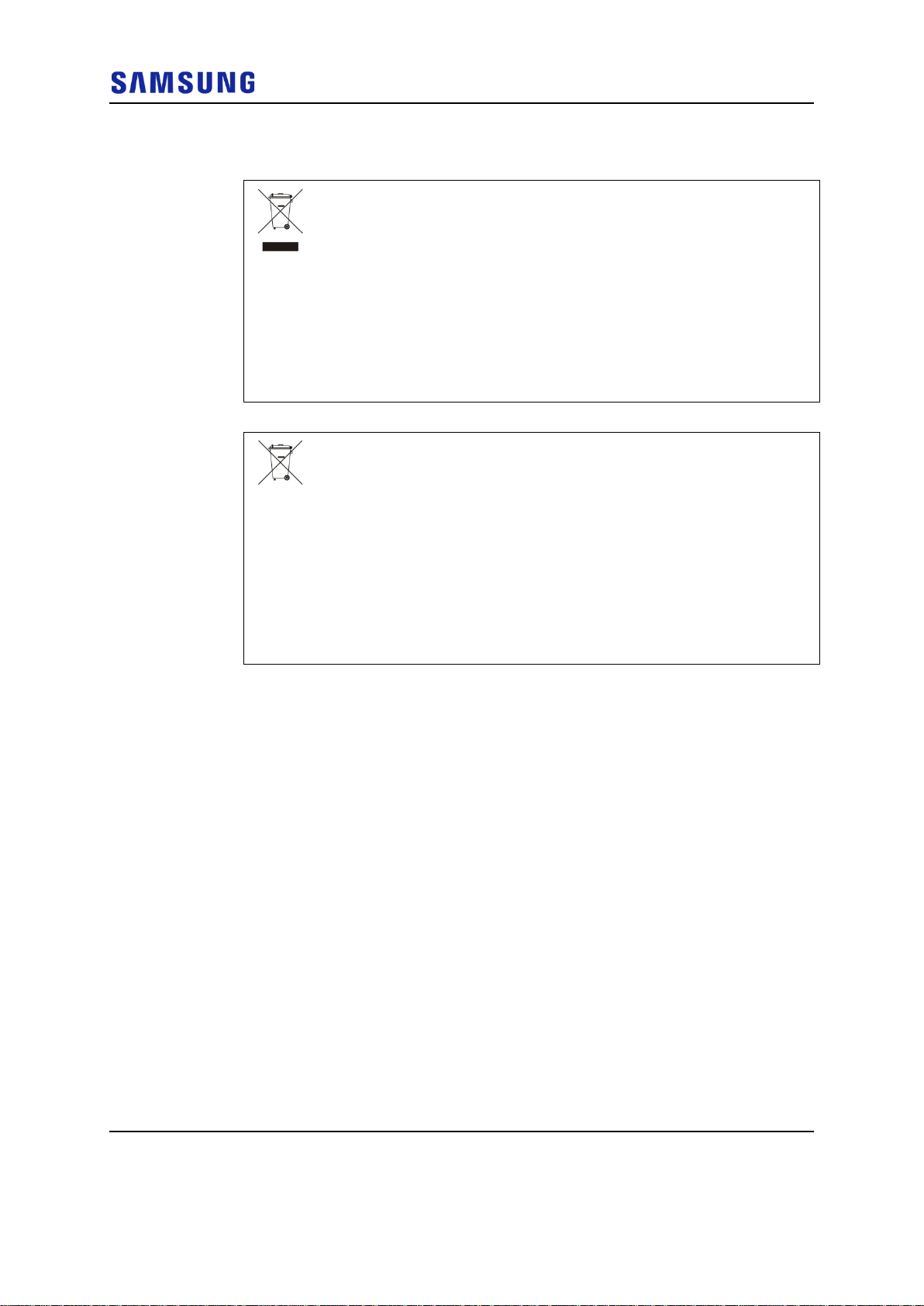
Equipment Markings
This marking on the product, accessories or literature indicates that the
product and its electronic accessories (e.g. charger, headset, USB cable)
should not be disposed of with other household waste at the end of their
working life. To prevent possible harm to the environment or human health
from uncontrolled waste disposal, please separate these items from other
types of waste and recycle them responsibly to promote the sustainable
reuse of material resources.
Household users should contact either the r etailer where they purchased
this product, or their local government office, for details of where and how
they can take these items for environmentally safe recycling.
Business users should contact their supplier and check the terms and
conditions of the purchase contract. This product and its electronic
accessories should not be mixed with other commercial wastes for disposal.
(Applicable in countries with separate collection systems.)
The marking on the battery, manual or packaging indicates that the battery
Confidential
marked, the chemical symbols Hg, Cd or Pb indicate that the battery
contains mercury, cadmium or lead above the reference levels in EC
Directive 2006/66.
The battery incorporated in this product is not user replaceable. For
information on its replacement, please contact your service provider. Do not
attempt to remove the battery or dispose it in a fire. Do not disassemble,
collection site will take the appropriate measures for the recycling and
treatment of the product, including the batter y .
5G CPE Outdoor Install atio n Manual v1.0 xii
Copyright © 2018, All Rights Reserved.
Page 13
Confidential
Chapter 1
Before
Installation
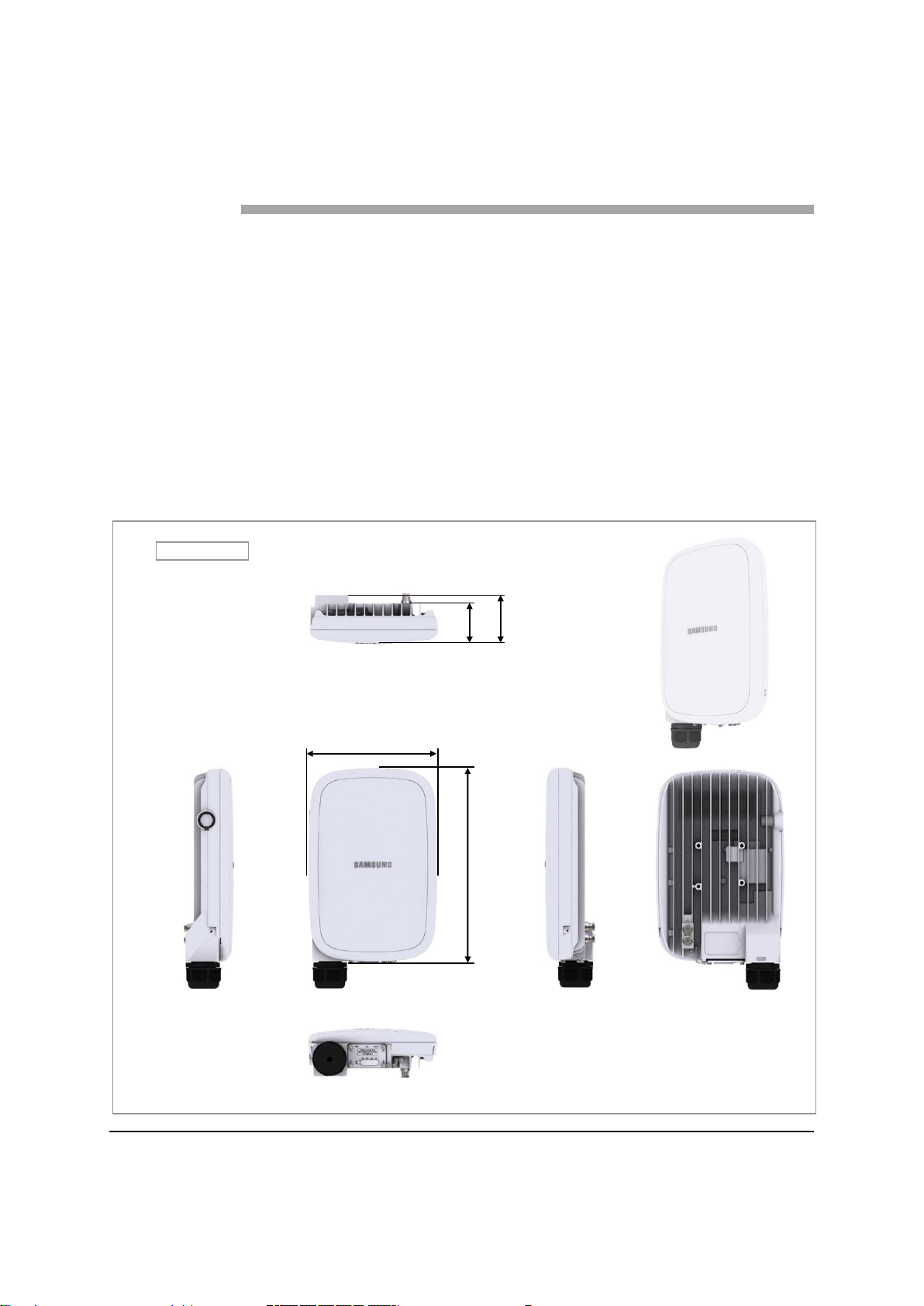
6.77 (172)
2.52
(64)
[Front View]
[Rear View]
[Right View]
Unit: in. (mm)
2.08
10.19 (259)
[Left View]
[Top View]
[Bottom View]
This chapter introduces the CPE Outdoor and describes the items that you should
know before installation.
System View and External Interface
This section provides the pictorial view of the CPE Outdoor and its interfaces.
CPE Outdoor View
The figure below depicts the physical structure of the CPE Outdoor.
Figure 1. CPE Outdoor View
(53)
5G CPE Outdoor Install atio n Manual v1.0 1
Copyright © 2018, All Rights Reserved.
Page 14

Chapter 1 Before Installation
[Bottom View]
[Top View]
[Left View]
13.71 (348.4)
2.08
(53)
Unit: in. (mm)
[Right View]
[Rear View]
[Front View]
6.86 (174.4)
2.52
(64)
Figure 2. CPE Outdoor View (with Cable Cover)
Confidential
5G CPE Outdoor Install atio n Manual v1.0 2
Copyright © 2018, All Rights Reserved.
Page 15
Chapter 1 Before Installation
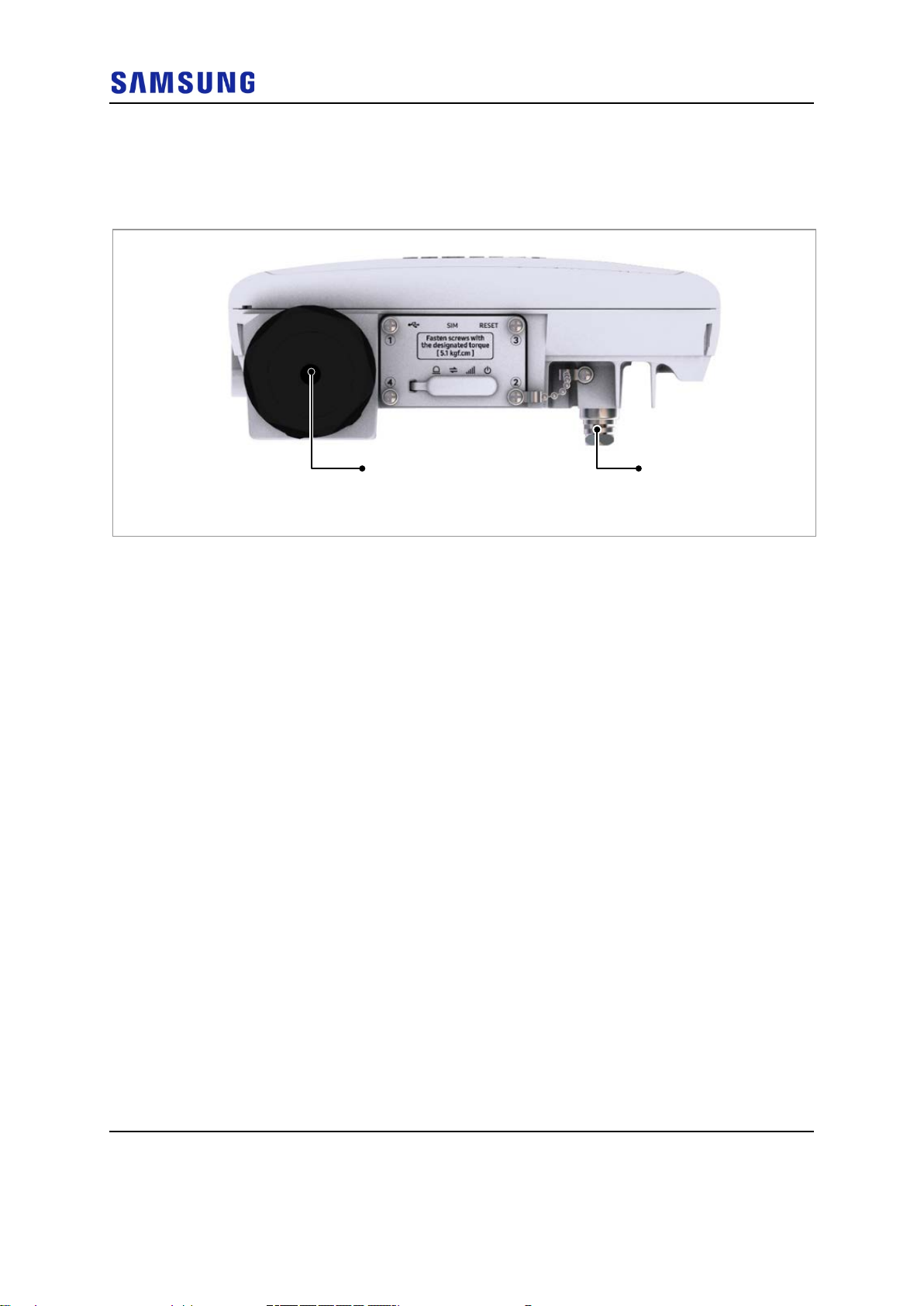
Ground Terminal
LAN
[Bottom View]
CPE Outdoor External Interface
The figure below depicts the external interface structure of the CPE Outdoor.
Figure 3. CPE Outdoor External Interface
Confidential
5G CPE Outdoor Install atio n Manual v1.0 3
Copyright © 2018, All Rights Reserved.
Page 16
Chapter 1 Before Installation
Item
COF110-284
Dimension (W × D × H)
6.77 in.(172 mm) × 2.08 in.(53 mm) × 10.19 in.(259 mm)
Specifications
The table below lists the main specifications of the CPE Outdoor.
Table 1. Specifications
Technology 5G (follows Verizon 5GTF's latest version)
Operating Frequency 27.5-28.35 GHz
Channel Bandwidth 100 MHz
Operating Bandwidth 100 MHz × 8 Carrier
Antenna Configuration Integrated Antenna
• Data Channel: 2Tx/2Rx
• RF chain per Data Channel: 32
RF Output Power 36 dBm/Path (EIRP, Antenna Gain: 19 dBi )
Power PoE (Midspan)
* Use the power supplies that meets LPS.
Ethernet RJ45 1 Port
• PoE, 100 Base-TX or 1000 Base-T
USB USB 2.0 1 Port
Bluetooth BLE4.0
Nano-SIM 1 Port
USIM
LED
Factory Reset 1EA (Push Button Switch)
Operational Temperature -30 to 55°C without solar load
Humidity 5-100 % RH, condensing, not to exceed 30 g/m3 absolute humidity
IP rating IP65
EMC FCC Part 15 Subpart B
FCC FCC Part 30 (5G RF)
Installation Pole/Wall mounting bracket
• Replaceable regular SIM
• support Class C operating conditions: terminal or a smart card operating at 1,8 V
± 10 %
Total: 4 EA
• Power: Green LED
• Signal: 3 Color (Green/Amber/Red)
• Connection: 3 Color (Green/Amber/Red)
• Alarm: 3 Color (Green/Amber/Red)
Confidential
Volume < 2.5 L (main frame, excluding bracket)
Weight < 4.4 lb (2.0 kg) (main frame, excluding bracket)
Power Consumption Typical 25 W, a maximum of 35 W
5G CPE Outdoor Install atio n Manual v1.0 4
Copyright © 2018, All Rights Reserved.
Page 17
Chapter 1 Before Installation
Cautions for Installation
Observe the safety instructions described in this section when installing the
system. Installation must be done in accordance with the applicable local electric
codes.
Before Installing
• Post warning signs in areas where high-voltage cables are installed.
• Post ‘off limit’ signs in areas where accidents are most expected.
• Use guardrails or fences to block open areas such as ditches, open roof areas,
and scaffolds.
Install the system in the restricted access area.
Use the power supplies that meets LPS.
Confidential
While Installing
The system power must be cut off before installing.
Ensure the power switch of power supply is off when installing the system.
Installing the system with power switch on may cause system damage or fatal
human injury when connecting or disconnecting cables.
Ensure that workers wear protection gloves and goggles to prevent injury from
debris while drilling holes in a wall or ceiling.
Do not wear accessories such as watches and rings to prevent electrical shock.
Cover unused ports with a cap. This prevents foreign substances from entering into
the unused ports.
To prevent foreign substances, outdoor air, and moisture from entering the cable
inlet (including cable gland and conduit), finish the inlet as follows:
Unused inlet: Use the hole finishing materials including cap and rubber packing.
Cable-installed inlet: After cable installation, block any space in the inlet with
tape, compressed sponge, rubber packing, and silicone.
5G CPE Outdoor Install atio n Manual v1.0 5
Copyright © 2018, All Rights Reserved.
Page 18

Chapter 1 Before Installation
After Installing
Remove any debris produced during the work and clean up the installation site.
In the system, the laser beam light runs through the optical cable. The workers
must handle the optical cables with care as the laser beam can seriously damage
the eyes.
Ensure that the workers do not damage installed cables while cleaning the system.
While cleaning the power supply device, take precaution that the device does not
come in contact with foreign objects that may cause power failure.
Confidential
5G CPE Outdoor Install atio n Manual v1.0 6
Copyright © 2018, All Rights Reserved.
Page 19
Chapter 1 Before Installation
Number
Name
Specification
Purpose of use
Apply a torque range
For fastening M6 SEMS (Hexagon+)
9
Power Extension Cable
100 ft.
Basic tool
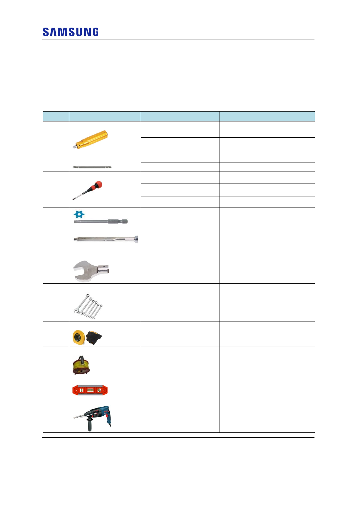
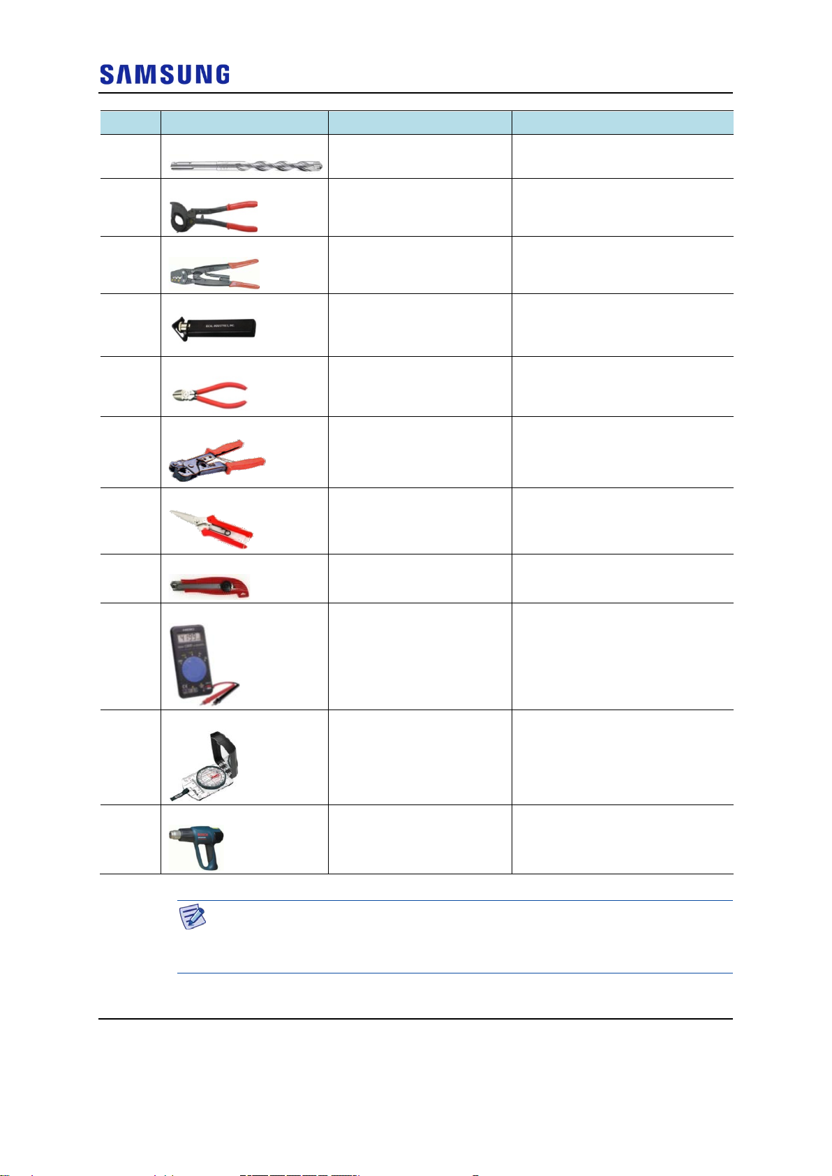
Installation Tools
The table below lists the basic tools needed for installation. The additional tools
required for each site need to be identified and arranged during a site survey before
starting the ins ta llation.
Table 2. Basic Installation Tools
Confidential
1 Torque Driver
2 Screw Driver Bit
3 Screw Driver
4
5 Torque Wrench
6 Torque Wrench Spanner
Head
7 Spanner
Apply a torque range
: 2-10 lbf·in
: 20-90 lbf·in
+, Number 2 For fastening M3 Screw
+, Number 3 For fastening M6 SEMS (Hexagon+)
+, Number 2 For loosening M3 Screw
+, Number 3 For loosening M6 SEMS (Hexagon+)
T25H For loosening M5 SEMS
T25H For fastening Torx Screw (T25H)
Apply a torque range
: 10-50 lbf·in
Apply Hexagon Head: 42 mm
(for 10~50 lbf·in)
42 mm For loosening Cable Gland Nut
For fastening M3 Screw
For fastening Cable Gland Nut
For fastening Cable Gland Nut
8 Tape Measure
10 Level
11 Hammer Drill
5G CPE Outdoor Install atio n Manual v1.0 7
Copyright © 2018, All Rights Reserved.
16 ft./150 ft. Tape measure for length
measurement
Normal For horizontality and verticality
Normal Wall type drilling
Page 20
Confidential
Number
Name
Specification
Purpose of use
Chapter 1 Before Installation
12 Concrete Drill Bit
13 Cable Cutter
14 Crimping Tool
15 Cable Stripper
16 Nipper
17 LAN Tool
18 Industrial Scissor
1/4 in. (6 mm) For Plastic Anchor
0.24-1.26 in. (6-32 mm) Cable cutting
14 AWG-4 AWG (1.5-16 mm2) Pressure ter mi nal for crim pin g
Apply cable thickness: 1.5-6.2
in. (4-16 mm)
Basic Tool For cutting cable
Basic Tool RJ45 crimper
Basic Tool Cutting
Cable sheath for removal
19 Knife
20 Multi tester
21 Compass
22 Heating Gun
The required installation tools may vary depending on the site conditions.
In addition to the basic tools, protractor, ladder, safety equipment, and cleaning
tools must also be arranged, considering the site conditions.
Basic Tool Cutting
Digital Pocket Tester To measure voltage and current to
detect cable disconnection
Normal Check azimuth during installation
50-300°C Shrinking Heat Shrink Tube
5G CPE Outdoor Install atio n Manual v1.0 8
Copyright © 2018, All Rights Reserved.
Page 21
Confidential
Chapter 2
Installing System
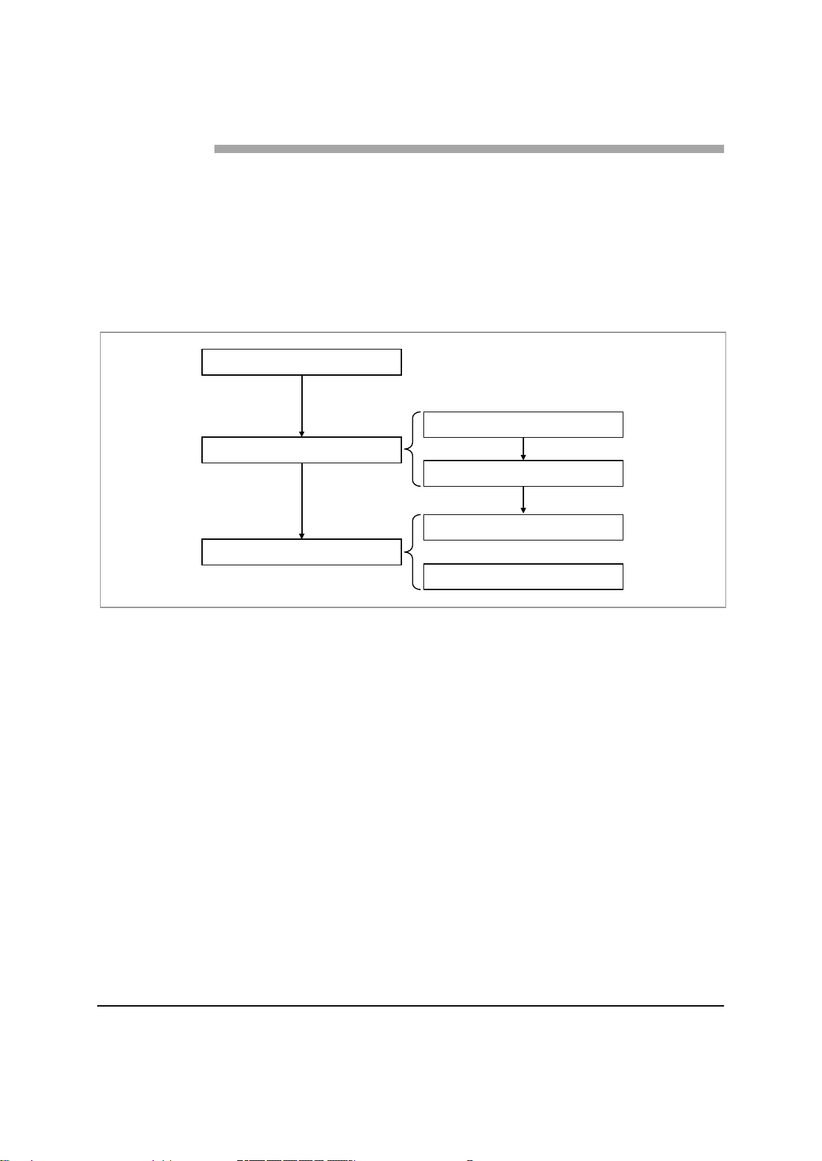
Foundation Work
Unpacking and Transporting
Fixing System
Unpacking Items
Bringing in Items
Pole Type
Wall Type
This chapter describes the installation procedure of the CPE Outdoor.
Installation Procedure
The figure below depicts the procedure to install the CPE Outdoor.
Figure 4. Procedure to Install the CPE Outdoor
5G CPE Outdoor Install atio n Manual v1.0 9
Copyright © 2018, All Rights Reserved.
Page 22

Chapter 2 Installing System
Unit: in. (mm)
[Top View]
[Front View]
≥ 8 (200)
≥ 8 (200)
W: 6.86 (174.4)
H: 13.71 (348.4)
4.88 (124)
Unit: in. (mm)
[Top View]
[Front View]
≥ 8 (200)
W: 6.86 (174.4)
H: 13.71 (348.4)
4.88 (124)
System Arrangement
A minimum distance must be secured around the CPE Outdoor, in each direction
for installation and maintenance.
The figure below depicts the minimum distance that must be secured for a pole
type installation of the CPE Outdoor.
Figure 5. CPE Outdoor Arrangement Pole type Installation
≥ 16 (400)
≥ 8 (200)
Confidential
≥ 16 (400)
The figure below depicts the minimum distance that must be secured for a wall
type installation of the CPE Outdoor.
Figure 6. CPE Outdoor Arrangement Wall type Installation
≥ 16 (400)
≥ 32 (800)
≥ 32 (800)
≥ 16 (400)
5G CPE Outdoor Install atio n Manual v1.0 10
Copyright © 2018, All Rights Reserved.
Page 23

Chapter 2 Installing System
Transporting and Unpacking
This section details how to transport the items to the installation place and
describes the procedure to unpack cabinets and other components.
Bringing in Items
Take care of the following at each stage of transportation of the items:
• Before moving a system, check the storage place for the system and remove
obstacles in advance.
• When carrying the system:
o Fasten the system firmly to the transport vehicle or carrier to prevent
damage to the system from a vibration or shock.
o Use an elevator to prevent accidents. However, if the system must be
carried by people, ensure there are enough people to carry the system.
• The system must not be shocked physically.
Confidential
• Care must be taken to protect the system from dust, moisture, and static
electricity.
Unpacking Items
To unpack the items, ensure the following:
• The items must be packed until they reach the installation place.
• The items are classified in accordance with each job specification and stored at
a place that does not interfere with working.
• Unpacked systems must be installed immediately. If immediate installation of
the systems is not planned, the systems must be stored in the installation place
temporarily.
• Unpack only external packing, leaving the internal packing in an unpacked
status.
• Unpack the inner packaging after each system is placed on its installation
location.
• Dispose of by-products (packaging waste) in accordance with waste
management rules. Do not recycle the by-products.
5G CPE Outdoor Install atio n Manual v1.0 11
Copyright © 2018, All Rights Reserved.
Page 24

Item List
Unit Bracket
Steel Band
AC/DC Adaptor
Cable Cover
Mounting Bracket
Power Cord
Figure 7. Item List
Confidential
Chapter 2 Installing System
The figure below depicts the packed item list.
5G CPE Outdoor Install atio n Manual v1.0 12
Copyright © 2018, All Rights Reserved.
Page 25

Confidential
Category
Description
M3 Screw Outdoor
Window Cover
Chapter 2 Installing System
Fixing System
This section details the procedure to fix the CPE Outdoor.
Inserting SIM
To insert the Subscriber Identity Module (SIM)
1 Ensure that the items mentioned in the table below are available.
Table 3. Parts and Tools for inserting the SIM
Recommended Torque Value M3 Screw 4.4 lbfin (5.1 kgf·cm)
Working Tools
• Torque Driver (2-10 lbfin)
• Screw Driver Bit (‘+’, Number 2)
• Screw Driver (‘+’, Number 2)
2 Unscrew the screw for fixing window cover and separate the window cover.
Figure 8. Inserting SIM (1)
3 Insert the SIM into the SIM slot.
5G CPE Outdoor Install atio n Manual v1.0 13
Copyright © 2018, All Rights Reserved.
Page 26

Chapter 2 Installing System
M3 Screw
Window Cover
SIM Slot
SIM
Figure 9. Inserting SIM (2)
Confidential
4 Fix the window cover by fastening screws in numerical order (1 2 3
4).
Figure 10. Inserting SIM (3)
When fixing the window cover, make sure to check the order of screw fastening
and standard torque value (4.4 lbfin).
5G CPE Outdoor Install atio n Manual v1.0 14
Copyright © 2018, All Rights Reserved.
Page 27

Confidential
Category
Description
Screw (T25H)
0.2 in.
0.2 in.
Chapter 2 Installing System
Fixing Unit Bracket Assembly
To fix a unit bracket assembly on the CPE Outdoor
1 Ensure that the items mentioned in the table below are available.
Table 4. Parts and Tools for Fixing Unit Bracket on CPE Outdoor
Parts Unit Bracket Assembly 1 Set
Fasteners M5 × L14 SEMS (T25H) 4 EA
Recommended Torque Value M5 SEMS 25 lbfin (29 kgf·cm)
Working Tools
2 Unfasten the left/right side screws of unit bracket assembly by 0.2 in.
• Torque Driver (20-90 lbfin)
• Screw Driver Bit (T25H)
• Screw Driver (T25H)
Figure 11. Fixing Unit Bracket Assembly (1)
3 Fix the unit bracket to the fixing hole of the CPE Outdoor rear using fasteners
as shown in the figure below.
5G CPE Outdoor Install atio n Manual v1.0 15
Copyright © 2018, All Rights Reserved.
Page 28

Chapter 2 Installing System
Category
Description
Pole Size (Diameter)
Length of Steel Band
M5 SEMS
(T25H)
Unit Bracket Assembly
M6 SEMS
(T25H)
Figure 12. Fixing Unit Bracket Assembly (2)
Confidential
Fixing System on a Pole Type
The CPE Outdoor can be fixed on a pole. This section details both procedures.
To fix a mounting bracket on the pole
1 Ensure that the items mentioned in the table below are available.
Table 5. Parts and Tools for Fixing Mounting bracket on the Pole
Parts Mounting bracket 1 EA
Fastener Steel Band 2 EA
Recommended Torque Value Steel Band Fixing Screw 48.5 lbfin (56.1 kgfcm)
Working Tools
• Torque Driver (20-90 lbfin)
• Screw Driver Bit ('+', Number 3)
The standard of the pole on which the mounting bracket can be attached using
steel bands is 32 A to 100 A.
5G CPE Outdoor Install atio n Manual v1.0 16
Copyright © 2018, All Rights Reserved.
32 A (1.68 in./42.7 mm)~100 A
(4.5 in./114.3 mm)
436 mm
Page 29

Chapter 2 Installing System
Steel Band
Fixing Screw
Mounting Bracket
Steel Band
2 Pass the steel band through the fixing hole of the mounting bracket, as shown
in the figure below.
Figure 13. Fixing Mounting bracket on the Pole (1)
Confidential
3 Place a mounting bracket to the pole and fix the steel band, as shown in the
figure below.
Figure 14. Fixing Mounting bracket on the Pole (2)
5G CPE Outdoor Install atio n Manual v1.0 17
Copyright © 2018, All Rights Reserved.
Page 30

Confidential
If it is level, the bubble of the
center of both lines.
Chapter 2 Installing System
When fixing the mounting bracket, ensure that the ‘UP’ arrow is upward.
4 Check the level of the mounting bracket on the pole and adjust the level, as
detailed in the figure below.
Figure 15. Fixing Mounting bracket on the Pole (3)
spirit level is positioned at the
When fixing the mounting bracket on the pole, be sure to check the level of the
bracket. After finishing the installation, adjust the level minutely.
When poor leveling happens, adjust the position of fasteners used to fix the
mounting bracket.
5G CPE Outdoor Install atio n Manual v1.0 18
Copyright © 2018, All Rights Reserved.
Page 31

Chapter 2 Installing System
Category
Description
M5 SEMS (T25H)
Mounting Bracket_Hook Groove
M5 SEMS (T25H)
[Left View]
[Right View]
To fix the CPE Outdoor on the pole mounting bracket
1 Ensure that the items mentioned in the table below are available.
Table 6. Parts and Tools for Fixing CPE Outdoor on the Pole
Confidential
Parts Fasteners M5 × L14 SEMS (T25H)
(Fastened to the unit bracket)
Recommended Torque Value M5 SEMS 25 lbfin (29 kgf·cm)
Working Tools
• Screw Driver Bit (T25H)
• Torque Driver (20-90 lbf·in)
2 EA
2 Hang the fasteners over the top groove of the pole mounting bracket, and then
fix it using fasteners. This is depicted in the figure below.
Figure 16. Fixing CPE Outdoor on the Pole Mounting Bracket
5G CPE Outdoor Install atio n Manual v1.0 19
Copyright © 2018, All Rights Reserved.
Page 32

Chapter 2 Installing System
Category
Description
Unit: in. (mm)
: Anchor Bolt Hole
[Rear View]
2.49 (64)
3.69 (93.8)
Fixing System on a Wall Type
A CPE Outdoor can be fixed on wall using a mounting bracket. This section
details the procedures for fixing the mounting bracket on the wall and fixing the
CPE Outdoor on the bracket.
To mark on the wall
1 Ensure that the items mentioned in the table below are available.
Table 7. Tools for Marking
Confidential
Working Tools
Perform a leveling test before drilling by referring to System Leveling, to ensure
the positions marked are horizontal or vertical. If the result shows the marked
positions are not horizontal or vertical, modify the marking positions.
When the position to place the system is determined, place the system on that
position and then mark the positions where anchor bolts are to be fixed. This
reduces the marking error range.
2 Check the distance between the location for fixing the CPE Outdoor and the
anchor bolt hole, as shown in the figure below.
Figure 17. CPE Outdoor Marking Dimensions for Wall Type
• Tape Measure
• Permanent Maker
• Level
5G CPE Outdoor Install atio n Manual v1.0 20
Copyright © 2018, All Rights Reserved.
Page 33

Chapter 2 Installing System
Category
Description
Category
Anchor Bolt
Drill Bits
Hole Depth
[O]
* Remove the debris from the drilled hole.
[Anchor Hole Cross Section]
35 mm
(1.4 in)
[X]
1/4 in.
2.49 (64)
Unit: in. (mm)/ Marking Point
If it is level, the bubble of the
center of both lines.
3.69 (93.8)
3 Place the mounting bracket on the fixing location, check the level status using
a level, and adjust the level of the bracket assembly.
4 If the level status is normal, mark the anchor bolt holes on the wall. This is
detailed in the figure below.
Figure 18. Marking Wall Type
spirit level is positioned at the
Confidential
To drill the anchor holes
1 Ensure that the items mentioned in the table below are available.
Table 8. Tools for Drilling
Working Tools Hammer Drill
Drill Bit (1/4 inch)
Vacuum Cleaner
Table 9. Anchor Bolt Drill Bits and Hole Depth
CPE Outdoor Φ 6 1/4 in. (6 mm) 1.4 in. (35 mm)
(6 mm)
5G CPE Outdoor Install atio n Manual v1.0 21
Copyright © 2018, All Rights Reserved.
Page 34

Chapter 2 Installing System
Category
Description
Vacuum Cleaner
1/4 in.
(6 mm)
2 Drill anchor holes at the marked points. Remove dust from the holes using a
vacuum cleaner.
Table 10. Drilling Example
Confidential
Hammer Drill
To fix the mounting bracket on the wall
1 Ensure that the items mentioned in the table below are available.
Table 11. Parts and Tools for Fixing Mounting Bracket on the Wall
Parts Mounting Bracket 1 EA
Fastener M4 × L25 PH+ Taptite Screw 4 EA
Φ 6 × L30 Plastic Anchor 4 EA
Recommended Torque Value M4 PH+ Tapping Screw 13 lbf·in (15 kgfcm)
Working Tools Torque Driver (6~22 lbf·in)
Screw Driver Bit ('+', No. 2)
2 Fix the Φ 6 plastic anchors to the holes drilled on the wall.
5G CPE Outdoor Install atio n Manual v1.0 22
Copyright © 2018, All Rights Reserved.
Page 35

Chapter 2 Installing System
M4 PH+ Taptite Screw
Mounting Bracket
Wall
Plastic Anchor
Figure 19. Fixing Mounting Bracket on the Wall (1)
3 Place the mounting bracket along with the fixed plastic anchors.
Figure 20. Fixing Mounting Bracket on the Wall (2)
Confidential
When fixing the mounting bracket, ensure that the ‘UP’ arrow is upward.
5G CPE Outdoor Install atio n Manual v1.0 23
Copyright © 2018, All Rights Reserved.
Page 36

Chapter 2 Installing System
Category
Description
M5 SEMS (T25H)
Mounting Bracket_Hook Groove
M5 SEMS (T25H)
[Left View]
[Right View]
To fix the CPE Outdoor on the wall
1 Ensure that the items mentioned in the table below are available.
Table 12. Parts and Tools for Fixing CPE Outdoor on the Wall
Confidential
Parts Fasteners M5 × L14 SEMS (T25H)
(Fastened to the unit bracket)
Recommended Torque Value M5 SEMS 25 lbfin (29 kgf·cm)
Working Tools
• Screw Driver Bit (T25H)
• Torque Driver (20-90 lbf·in)
2 EA
2 Hang the fasteners over the top groove of the wall mounting bracket, and then
fix it using fasteners. This is depicted in the figure below.
Figure 21. Fixing CPE Outdoor on the Wall Mounting Bracket
5G CPE Outdoor Install atio n Manual v1.0 24
Copyright © 2018, All Rights Reserved.
Page 37

Confidential
Category
Description
M5 SEMS (T25H)
[Left View]
[Right View]
Chapter 2 Installing System
System Tilting & Swiveling
To ti lt the system
1 Ensure that the items mentioned in the table below are available.
Table 13. Tools for System Tilting
Recommended Torque Value M5 SEMS 25 lbfin (29 kgf·cm)
Working Tools
2 Turn the left/right side screws of the mounting bracket two turns
counterclockwise.
Figure 22. System Tilting (1)
• Screw Driver Bit (T25H)
• Torque Driver (20-90 lbf·in)
• Screw Driver (T25H)
3 Adjust the tilting angle by pulling the up and down tilt of the CPE outdoor.
o Up tilting: +6°/+12°/+15°
o Down tilting: -6°/-12°/-15°
5G CPE Outdoor Install atio n Manual v1.0 25
Copyright © 2018, All Rights Reserved.
Page 38

Chapter 2 Installing System
[UP Tilting]
[Down Til t i ng]
Figure 23. System Tilting (2)
Confidential
4 Turn the left/right side screws of mounting bracket clockwise and fix it.
5G CPE Outdoor Install atio n Manual v1.0 26
Copyright © 2018, All Rights Reserved.
Page 39

Chapter 2 Installing System
Category
Description
M5 SEMS (T25H)
[Top View]
M5 SEMS (T25H)
[Left View]
[Right View]
Figure 24. System Tilting (3)
To swiv el the system
Confidential
1 Ensure that the items mentioned in the table below are available.
Table 14. Tools for System Swiveling
Recommended Torque Value M5 SEMS 25 lbfin (29 kgf·cm)
Working Tools
• Screw Driver Bit (T25H)
• Torque Driver (20-90 lbf·in)
• Screw Driver (T25H)
2 Turn the top side screw of the unit bracket two turns counterclockwise.
Figure 25. System Swiveling (1)
5G CPE Outdoor Install atio n Manual v1.0 27
Copyright © 2018, All Rights Reserved.
Page 40

Chapter 2 Installing System
[Right Swivelling]
[Left Swivelling]
3 Adjust the swiveling angle by pulling the up and down tilt of CPE outdoor.
o Left swiveling: 5°/10°/15°/20°/25°
o Right swiveling: 5°/10°/15°/20°/25°
Figure 26. System Swiveling (2)
Confidential
4 Turn the top side screw of the unit bracket clockwise and fix it.
5G CPE Outdoor Install atio n Manual v1.0 28
Copyright © 2018, All Rights Reserved.
Page 41

Chapter 2 Installing System
Degree of Tilting
Degree of Swivelling
Remark
M5 SEMS (T25H)
[Top View]
Figure 27. System Swiveling (3)
When tilting and swiveling the CPE at the same time, the possible range is as
follows:
Confidential
+15° Left 25°~Right 25° 0° Left 25°~Right 25° -
-15° Left 15°~Right 25° When wall install
5G CPE Outdoor Install atio n Manual v1.0 29
Copyright © 2018, All Rights Reserved.
Page 42

Confidential
Chapter 3
Connecting
Cables
Grounding
Interface Cable Connection
Connecting ground cable
Connecting LAN cable
This chapter describes the procedures to connect cables to a CPE Outdoor system
and to label the cables.
Cabling Procedure
The figure below depicts the procedure to connect system cables.
Figure 28. Procedure to Connect System Cable
5G CPE Outdoor Install atio n Manual v1.0 30
Copyright © 2018, All Rights Reserved.
Page 43

Chapter 3 Connecting Cables
Cable Installation
Connector Attachment
Identification Tag Attachment
Connector Assembly
When assembling the
Cable Path Inspection
Cable Cutting
Cable Binding
Guidelines for Cable Connections
The figure below depicts the sequence of operations for connecting cables to the
system.
Figure 29. Cable Connection Procedure
connector at the site
Confidential
When cutting the cable after installation, ensure tha t the connect or is disco nnec ted .
The cable installation while the connector is connected to the system may cause
contact failure, or damage to the assembled connector and the cable, due to cable
tension or operator mistakes.
The sequence of cable cutting and installation of the cable workflow can be
changed depending on the field situation such as "cutting after installing" or
"installing after cutting".
5G CPE Outdoor Install atio n Manual v1.0 31
Copyright © 2018, All Rights Reserved.
Page 44

Chapter 3 Connecting Cables
Cable Path Inspection
When installing a cable that interconnects the rectifier, Main Ground Bar (MG B),
and backhaul device, within the system, cable path, length, and cable installation
method must be inspected.
To inspect the cable path, ensure the following.
• A minimum cable length must be selected, so that the length does not affect
the cable installation and maintenance.
• The cable must be placed in a location where the cable is not damaged by
external factors such as power line, flooding, and footpaths.
• In areas where the cable may be damaged by external factors, ensure that
measures are taken to prevent damage to the cable, such as cable tray, ducts,
and flexible pipe.
Cable Cutting
Measure the exact distance after carefully checking the route, and cut the cable
using a cutting tool.
Confidential
To cut the cable, follow these guidelines:
• Cut the cable to the length determin ed in the Cable Path Inspection step.
• Use a dedicated cable cutting tool.
• Cut the cable at right angles.
• Be careful to keep the cable away from moisture, iron, lead, dust, or other
foreign material when cutting.
• Remove any foreign material attached to the cable using solvent and a brush.
Cable Installation
This process involves running the cable along the cabling path to the target
connector of the system or an auxiliary device. This is done after the cable path
inspection and cable cutting are completed.
To install the cab le, fol lo w these guidelines:
• Be careful not to damage the cable.
• If the cable is damaged, cut out the damaged section before installing, or
replace the cable.
• Run the cable so that it is not tangled. In particular, when installing the cable
from a horizontal section to a vertical section, be careful not to reverse the
upper and lower lines of the cable.
• Always use the maximum curvature radius possible, and ensure that the
minimum curvature radius specification is complied with.
5G CPE Outdoor Install atio n Manual v1.0 32
Copyright © 2018, All Rights Reserved.
Page 45

Chapter 3 Connecting Cables
No
Cable
Allowed Cable Bending Radius
If the allowed cable bending radius is specified by the manufacturer, comply with the bend radius specified.
• If the cable needs to be protected, use a suitable protective cover such as a
PVC channel, spiral sleeve, flexible pipe, and cable rack.
• Install the DC power cable and the data transmission cable away from the AC
power cable to prevent electromagnetic indu c t ion .
The table below provides the recommended minimum allowed cable bend radius
of different types of cables.
Table 15. Recommended Minimum Allowed Cable Bending Radius
Confidential
1 Ground/Power Cable
2 UTP Cable 4 × OD
※
• Operation: 8 × OD
• Installation: 12 × OD
Cable Binding
This process involves fixing and arranging an installed cable using binding thread,
cable ties, binding wire, and ram clamps.
Follow these guidelines when binding a cable.
• Be careful not to damage the cable during binding.
• Use proper cable binding tools according to the target location (indoor or
outdoor) and the type of the cable (power supply cable, optical cable, or feeder
line).
• Ensure the cutting sections of the cable tie and the binding line are not exposed
to the outside. This may cause damage to the cables or personal injury.
• Cut off the remainder of the cable thread by leaving about 50 mm of extra
length to prevent the knot from easily getting untied.
• If there is a chance of contact-failure to occur in the connector connection due
to tension, bind the cable at the closest location to the connector.
Connector Attachment
This process involves assembling a connector to an installed cable or to a device
on the site.
Follow these guidelines when attaching the connector.
• Ensure operator is fully aware of the connector assembly method before
assembling the connector. Assemble the connec tor in acco rdan ce with its pin
map.
• Each connector has a hook to prevent its core positions from being changed.
• Check the corresponding grooves before connecting the connector to another
connector.
5G CPE Outdoor Install atio n Manual v1.0 33
Copyright © 2018, All Rights Reserved.
Page 46

Chapter 3 Connecting Cables
• Use a heat shrink tube at the connector connection for cables that are installed
outdoors, such as feeder lines, to prevent water leakage and corrosion from
occurring at the part exposed to the outside.
• Connect each cable of the connector assembly in a straight line.
• Be careful when connecting the cable so that contact failure does not occur at
the connector connection due to tension.
Identification Tag Attachment
This process involves attaching a marker cable tie, a nameplate, and a label to both
ends of a cable (connections to a connector) to identify the use of the cable and the
cabling path.
Follow these guidelines when attaching an identification tag.
• When installing the cable outdoor, use relief engraving and coated labels to
prevent the markings from being erased.
• Since the form and attachment method for identification tags are different for
each provider, consult with the provider before attaching the tags.
Confidential
When connecting the cables, always connect the ground cable first. If a worker
contacts the equipment, connects a cable, or performs maintenance without
connecting the ground cable, the system can be damaged or the worker may be
injured due to static electricity and short circuit.
When performing cable work for the system, proceed with the ground work before
any other work to prevent errors occurring due to static electricity and other
reasons.
After completing cable installation, unused ports must be capped.
When installing, take care not to overlap or tangle the cables. In addition, consider
future expansion. Install the DC power cable and data transmission cable away
from the AC power cable to prevent electromagnetic induction.
Ensure the work is done by personnel properly trained for the cabling job.
5G CPE Outdoor Install atio n Manual v1.0 34
Copyright © 2018, All Rights Reserved.
Page 47

Chapter 3 Connecting Cables
From
To
Cable
2
MGB
Home Router
AC Outlet
1) Ground Cable
3) Ethernet Cable
[Bottom View]
[PoE Midspan]
4) Ethernet Cable
2) AC Power Cable
[Inside Building]
[Outside Building]
Cabling Diagram
The cabling diagram of the system is as follows.
The figure below depicts the cabling diagram of the CPE Outdoor.
Figure 30. Cable Diagram
Confidential
The table below lists the main specifications of the CPE Outdoor cable
connections.
Table 16. CPE Outdoor Connection Cable
MGB CPE Outdoor 1 Ground Cable
: 14 AWG × 1C
PoE Midspan AC Outlet
CPE Outdoor 3 Ethernet Cable
Home Router 4 Ethernet Cable
AC Power Cord
: UTP, 24 AWG, 4P, CAT.5e (Outdoor Type)
: UTP, 24 AWG, 4P, CAT.5e (Indoor Type)
The inlet hole finishing method of external equipment must be done after
consultation with the operation company, if the cable is connected to external
equipment, such as optical distribution box.
- Cables: Power cable, Ethernet cable
5G CPE Outdoor Install atio n Manual v1.0 35
Copyright © 2018, All Rights Reserved.
Page 48

Chapter 3 Connecting Cables
Category
Description
Grounding
Grounding is the process of operating an electronic system such as a power supply
system, communication system, and control system, stably without damage from
lightning, transient-current, transient-voltage, and electric noise. Grounding also
helps in preventing injury from electric shock.
Ground equipment minimizes the electrical potential of the electronic device to
that of the ground, which is zero electrical potential. This prevents electrification
of the electronic device.
Connect the ground cable first. In cabling, the connection of cables without the
connection to the ground cable may cause damage of the equipment or bodily
injury to personnel.
The purposes of the ground construction are as follows:
• To prevent human life and the system from over-current, over-voltage, and
Confidential
lightning
• To provide a discharge path for surge voltage generated by lightning and
power switch
• To protect the system from static electricity
• To eliminate or minimize the high-frequency potential in the system housing
• To provide a conductor for the balance and stab il ity of high-frequency current
• To stabilize the potential of the circuit against the ground
Connecting Ground Cable
When connecting the ground cables, connect the ground cable first before
installing the system to prevent errors.
To connect a ground cable
1 Ensure that the items mentioned in the table below are available.
Table 17. Parts and Tools for Connecting Ground Cable
Installation Section MGB-CPE Outdoor Ground Terminal
Cable 14 AWG × 1C
Bending Radius 8 × OD
Heat Shrink Tube
(Spec/Color/Length)
Pressure Terminal MGB Checking MGB specifications per site and preparing connecting parts
Ф 0.4 in. (10 mm)/Clear/2 in. (50 mm)
CPE
Outdoor
14 AWG, 2 Hole, Hole diameter: 1/4 in. (6.4 mm), Hole spacing: 0.63 in.
(16 mm)
5G CPE Outdoor Install atio n Manual v1.0 36
Copyright © 2018, All Rights Reserved.
Page 49

Confidential
Category
Description
[Rear View]
MGB
Ground Cable
Chapter 3 Connecting Cables
Fastener MGB Checking MGB specifications per site and preparing connecting parts
Recommended
Torque Value
Working Tools
CPE
Outdoor
M6 SEMS 43 lbf·in (50 kgf·cm)
• Cable Cutter
• Wire Stripper
• Crimping tool
• Heating Gun
• Nipper
• Screw Driver (‘+’, Number 3)
• Torque Driver (20-90 lbf·in.)
• Screw Driver Bit (‘+’, Number 3)
M6 × L12 SEMS (Hexagon+)/2 EA
For the pressure terminals of the cable, the UL Listed products or equivalent must
be used.
Example: Manufacturer-Panduit
CPE Outdoor: 14 AWG Pressure Terminal (LCD10-14A-L)
2 Install the ground cable from the MGB to the CPE Outdoor ground terminal as
shown in the figure below.
Figure 31. Connecting Ground Cable (1)
3 Assemble a pressure terminal and a heat shrink tube at the end of the CPE
Outdoor ground cable.
4 Align the pressure terminal to the mounting hole of the CPE Outdoor ground
terminal.
5 Firmly fix the pressure terminal onto the CPE Outdoor ground terminal using
fasteners.
5G CPE Outdoor Install atio n Manual v1.0 37
Copyright © 2018, All Rights Reserved.
Page 50

Chapter 3 Connecting Cables
M6 SEMS (Hexagon +)
Ground Cable
Pressure Terminal
Heat Shrink Tube (clear)
The figure below depicts steps 3 to 5.
Figure 32. Connecting Ground Cable (2)
Confidential
5G CPE Outdoor Install atio n Manual v1.0 38
Copyright © 2018, All Rights Reserved.
Page 51

Chapter 3 Connecting Cables
Category
Description
100~240 V AC
PoE Midspan
AC Distributor
(AC Outlet)
PoE
CPE Outdoor
Power Cabling
The figure below depicts the elements of a power supply device.
Figure 33. Power Equipment Elements
Handling the power cable incorrectly may damage the rack or cause an electric
short-circuit through the cable. Ensure the power switch of the rectifier or the
system is turned off before handling the power.
The fasteners for the power cable must be tightly secured to prevent electrical
accidents.
Confidential
The heat-resistant temperature of the power cable should be 90°C or more.
Install the power cable to the power port of the system by considering the radius of
curvature of its cable specification and then cut the cable. If the operator installs
the cable after cutting, there may be a length difference among the core wires at
the end of the cable because of the cable curvature. This may result in poor contact
after the cable is connected to the power port.
If you turn the power on and off rapidly (within 1 s), the counter electromotive
force caused by cable inductance can damage the system.
Connecting more than one power cable together may increase power loss.
It must be verified tha t the r ectifier or the power d is tr ibutor has an outpu t vo ltage
within the specified system input range before the power line is connected.
Connecting PoE Midspan Power Cable
To connect an AC power cable
1 Ensure that the items mentioned in the table below are available.
Table 18. Parts and Tools for Connecting Power Cable
Installation Section AC Outlet-PoE Midspan AC IN port
Cable AC Power Cord Assembly
Bending Radius 8 × OD
5G CPE Outdoor Install atio n Manual v1.0 39
Copyright © 2018, All Rights Reserved.
Page 52

Chapter 3 Connecting Cables
AC IN Port
PoE Midspan
AC Power Cord Assembly
[PoE Midspan]
AC Outlet
AC Power Cable
2 Install the AC power cable from the AC Distributor to the PoE midspan, as
shown in the figure below.
Figure 34. Connecting Power Cable (1)
3 Insert the connect or into the AC IN port of the PoE Midspan.
Confidential
Figure 35. Connecting Power Cable (2)
5G CPE Outdoor Install atio n Manual v1.0 40
Copyright © 2018, All Rights Reserved.
Page 53

Chapter 3 Connecting Cables
Category
Description
Filler
Cable Gland Nut
Cable Gland Body
Cable Gland Nut
Cable Gland Nut
Interface Cable Connection
This section describes the procedures to connect interface cables.
Remove Ethernet Cable
To remov e an Ethernet cable from the CPE Outdoor
1 Ensure that the items mentioned in the table below are available.
Table 19. Tools for Remove Ethernet Cable
Working Tools Spanner (Hexagon Head: 42 mm)
2 Unfasten the cab le gland nu t and sepa ra te the filler from the cable gland body.
Confidential
Figure 36. Remove Ethernet Cable (1)
3 Remove the RJ-45 plug from the system side’s LAN port. Press the latch with
the fingers, remove the cable from the connector.
5G CPE Outdoor Install atio n Manual v1.0 41
Copyright © 2018, All Rights Reserved.
Page 54

Chapter 3 Connecting Cables
Filler
Cable Gland Nut
Ethernet Cable
Ethernet Cable
Cable Gland Body
RJ-45 Plug
Latch
Ethernet Cable
Figure 37. Remove Ethernet Cable (2)
Confidential
4 Separate the filler and cable gland nut in order from the Ethernet cable.
Figure 38. Remove Ethernet Cable (3)
5G CPE Outdoor Install atio n Manual v1.0 42
Copyright © 2018, All Rights Reserved.
Page 55

Chapter 3 Connecting Cables
Category
Description
System side
Color Map
PoE Midspan
Function
Connecting Ethernet Cable
To connect an Ethern et cab le (CPE ~PoE Midspan)
1 Ensure that the items mentioned in the table below are available.
Table 20. Parts and Tools for Connecting Ethernet Cable (CPE~PoE Midspan)
Installation Section CPE Outdoor LAN port~PoE Midspan PoE/OUT port
Cable UTP, 24 AWG, 4P, CAT.5e (Outdoor Type)
Bending Radius 4 × OD
Connector CPE Outdoor RJ-45 Plug
PoE Midspan RJ-45 Plug
Recommended Torque
Value
Working Tools
Cable Gland Sealing Nut 47.4 lbf·in (56.6 kgf·cm)
• Torque Wrench (10~50 lbf·in)
• Torque Wrench Spanner Head (apply Hexagon Head: 42 mm)
• Spanner (Hexagon Head: 42 mm)
• LAN Tool
• LAN Cable Tester
• Nipper
Confidential
The table below provides the Ethernet cable connector pin map.
Table 21. Ethernet Cable Pin Map (CPE~PoE Midspan)
1 White/Orange 1 BI_DA+
2 Orange 2 BI_DA3 White/Green 3 BI_DB+
4 Blue 4 BI_DC+
5 White/Blue 5 BI_DC6 Green 6 BI_DB7 White/Brown 7 BI_DD+
8 Brown 8 BI_DD-
5G CPE Outdoor Install atio n Manual v1.0 43
Copyright © 2018, All Rights Reserved.
Page 56

Chapter 3 Connecting Cables
Filler
Cable Gland Nut
[Bottom View]
Ethernet Cable (Outdoor Type)
[PoE Midspan]
The Ethernet cable length between CPE and PoE Midspan is 3 m. If the cable
length is short, it can be connected by making a cable.
At this time, the total cable length of Home router-PoE Midspan-CPE should not
exceed a maximum of 100 m.
2 Install an Ethernet cable from the CPE Outdoor (LAN port) to the PoE
(PoE/OUT port), as shown in the figure below.
Figure 39. Connecting Ethernet Cable_CPE~PoE Midspan (1)
Confidential
3 Separate the cable gland nut and filler from the CPE LAN port cable gland.
Figure 40. Connecting Ethernet Cable_CPE~PoE Midspan (2)
4 Insert the cable gland nut and filler nut in order to the Ethernet cable.
5G CPE Outdoor Install atio n Manual v1.0 44
Copyright © 2018, All Rights Reserved.
Page 57

Chapter 3 Connecting Cables
CPE
RJ-45 Plug Latch
Filler
Cable Gland Nut
Ethernet Cable
Figure 41. Connecting Ethernet Cable_CPE~PoE Midspan (3)
Confidential
5 The latch of cable side connector should be toward the rear side.
Figure 42. Connecting Ethernet Cable_CPE~PoE Midspan (4)
Front Side
6 Insert the RJ-45 plug into the system side’s LAN port.
5G CPE Outdoor Install atio n Manual v1.0 45
Copyright © 2018, All Rights Reserved.
Page 58

Chapter 3 Connecting Cables
PoE (Midspan)
PoE/OUT Port
Filler
Cable Gland Nut
Cable Gland Body
Cable Gland Nut
Ethernet Cable
Cable Gland Body
RJ-45 Plug
Figure 43. Connecting Ethernet Cable_CPE~PoE Midspan (5)
Confidential
7 Push the filler to the cable gland body and connect the cable gland nut.
Figure 44. Connecting Ethernet Cable_CPE~PoE Midspan (6)
8 Insert the RJ-45 plug into the PoE side’s PoE/OUT port.
Figure 45. Connecting Ethernet Cable_CPE~PoE Midspan (7)
5G CPE Outdoor Install atio n Manual v1.0 46
Copyright © 2018, All Rights Reserved.
Page 59

Chapter 3 Connecting Cables
Category
Description
PoE Midspan
Color Map
Home Router
Function
To connect an Ethernet cable (PoE Midspan)
1 Ensure that the items mentioned in the table below are available.
Table 22. Parts and Tools for Connecting Ethernet Cable (PoE Midspan~Home Router)
Installation Section PoE Midspan DATA/IN port~Home Router
Cable UTP, 24 AWG, 4P, CAT.5e (Indoor Type)
Bending Radius 4 × OD
Connector PoE Midspan RJ-45 Plug
Home Router RJ-45 Plug
Working Tools
• LAN Tool
• LAN Cable Tester
• Nipper
Confidential
The table below provides the Ethernet cable connector pin map.
Table 23. Ethernet Cable Pin Map (PoE Midspan~Home Router)
1 White/Orange 1 BI_DA+
2 Orange 2 BI_DA3 White/Green 3 BI_DB+
4 Blue 4 BI_DC+
5 White/Blue 5 BI_DC6 Green 6 BI_DB7 White/Brown 7 BI_DD+
8 Brown 8 BI_DD-
The total Ethernet cable length of Home router-PoE Midspan-CPE should not
exceed a maximum of 100 m.
2 Install an Ethernet cable from the PoE (PoE/OUT port) to the Home router, as
shown in the figure below.
5G CPE Outdoor Install atio n Manual v1.0 47
Copyright © 2018, All Rights Reserved.
Page 60

Chapter 3 Connecting Cables
Icon
Name
Indicator
Description
Status
PoE (Midspan)
DATA/IN Port
Home Router
[PoE Midspan]
Ethernet Cable (Indoor Type)
Figure 46. Connecting Ethernet Cable_PoE Midspan~Home Rout er (1)
3 Insert the RJ-45 plug into the PoE side’s DATA/IN port.
Figure 47. Connecting Ethernet Cable_PoE Midspan~Home Rout er (2)
Confidential
To check a LED
1 After turning the power on for the CPE Outdoor, check the status of the LED.
Table 24. LED Indication
Signal
(5G Signal Strength)
2 Open the LED cover of the CPE Outdoor and check the status of the
3 × ( )
‘Signal ( )’ LED.
Amber blinking (3 times) then
off
Green On High: < -95 dBm
Amber On Medium: -95~-75 dBm
Red On Low: > -75 dBm
Off 5G disconnection
Initialization
5G CPE Outdoor Install atio n Manual v1.0 48
Copyright © 2018, All Rights Reserved.
Page 61

Chapter 3 Connecting Cables
LED Cover
Figure 48. Checking a LED (1)
Confidential
- When the status of the LED is ‘Amber on’ or ‘Green on’, you can finish the
installation. But it is recommended that you adjust the angle of installation for the
CPE to ensure ‘Green on’.
- If the ‘Red on’ status persists, then the direction of the CPE must be adjusted to
make the ‘Amber on’ or ‘Green on’ status.
- Contact a person in charge to take action if the ‘Red on’ status persists when you
adjust the CPE direction.
3 After checking whether the CPE Outdoor is in working order, close the LED
cover.
5G CPE Outdoor Install atio n Manual v1.0 49
Copyright © 2018, All Rights Reserved.
Page 62

Chapter 3 Connecting Cables
Figure 49. Checking a LED (2)
Confidential
5G CPE Outdoor Install atio n Manual v1.0 50
Copyright © 2018, All Rights Reserved.
Page 63

Confidential
Category
Description
Cable Cover
M3 Screw
M3 Screw
Chapter 3 Connecting Cables
Fixing Cable Cover
To fix the cable cover
1 Ensure that the items mentioned in the table below are available.
Table 25. Parts and Tools for Fixing Cable Cover on CPE Outdoor
Parts Cable cover 1 EA
Fasteners M3 Screw
* Included in cable cover
Recommended Torque Value M3 Screw 5.3 lbfin (6.1 kgf·cm)
Working Tools
• Torque Driver (2-10 lbf·in)
• Screw Driver Bit (+, Number 2)
2 Place the cable cover to the CPE Outdoor fixing hole and fix it using fasteners.
2 EA
Figure 50. Fixing Cable Cover on CPE Outdoor
5G CPE Outdoor Install atio n Manual v1.0 51
Copyright © 2018, All Rights Reserved.
Page 64

Confidential
Chapter 4
Inspect the
Installation
NO
YES
Sharing Inspection Results
Taking Corrective Actions
On-site Inspection
Inspection Checklist
Inspection Checklist/Corrective Actions
Sharing the Results of
Inspection Plan
Checking the Results of
This chapter describes the procedures to check the installation status.
The figure below depicts the overall procedure for inspecting the installation
status.
Figure 51. Installation Inspection Procedure
Corrective Actions
Corrective Actions and
Preparing Preventive Plan
Inspection Plan
Create an inspection sheet per system and select an inspector to set an inspection
schedule per site.
5G CPE Outdoor Install atio n Manual v1.0 52
Copyright © 2018, All Rights Reserved.
Page 65

Chapter 4 Inspect the Installa tion
Category
Check Items
Criteria
Result
Pass
Fail
On-site Inspection and Inspection Checklist
The on-site inspection is to perform inspe ction v isu ally or using instruments for
each specification, standard, and installation status, based on the inspection
checklist at the site where the system is installed.
The inspector must record the results onto the inspection checklist during or after
the field inspec tion.
Sharing Inspection Results and Taking Corrective Actions
The inspector must share the inspection results (inspection checklist and corrective
actions) with an installation operator. The installation operator must take the
corrective actions, if necessary, after reviewing the requirements.
Checking the Results of Corrective Actions
The inspector must check if the corrective actions are properly taken. If they are
not sufficient, the inspector must ask the installation operator to take the corrective
actions again.
Confidential
Sharing the Results of Corrective Actions and Preparing Preventive Plan
After the corrective actions are all completed, the inspector must share the results
with the installation operator and relevant departments. The inspector must prepare
a preventive plan to prevent the same or similar problems from re-occurring.
Construction Situation Checklist
The table below provides the checklist to check the installation of the CPE
Outdoor and other devices.
Table 26. Construction Situation Checklist
Installing
Equipment
Grounding Installation of ground bar Checking the separation of
Appearance of equipment
and mechanical parts
Placement of equipment
and mechanical parts
Leveling condition of
equipment and
mechanical parts
Validity of status and
specifications of fastening
bolt, nut, and washer
Cable specification Checking the specification
Equipment damage such as dent,
scratch, and crack
Maintenance and horizontal/vertical
placement
Horizontal/vertical statu s
Checking fasteners omission
Compliance with assembly order of
fasteners
Compliance with fastening torque value
communication/power/lightning
grounding
5G CPE Outdoor Install atio n Manual v1.0 53
Copyright © 2018, All Rights Reserved
Page 66

Confidential
Category
Check Items
Criteria
Result
Pass
Fail
Fastening condition of a connector
Chapter 4 Inspect the Installa tion
Cabling Cable damage
Proper installation route
Compliance with the radius of curvature
Cable binding status Binding status
Binding interval
Checking binding materials
Cable connection Assembly condition of a pressure
terminal
Fastening condition of a pressure
terminal
Checking compliance with fastening
torque value
Power Cable specification Checking the specification
Checking the limit distance
Cabling Cable damage
Proper installation route
Compliance with the radius of curvature
Cable binding status Binding status
Binding interval
Checking binding materials
Cable connection Checking cable connection
Other data
cables
Cable specification Checking the specification
Cabling Cable damage
Proper installation route
Compliance with the radius of curvature
Cable binding status Binding status
Binding interval
Checking binding materials
Cable connection Checking cable connection (Pin M ap)
Assembly condition of a connector
Opinion
5G CPE Outdoor Install atio n Manual v1.0 54
Copyright © 2018, All Rights Reserved
■
Page 67

Appendix A Acronyms
AC Alternating Current
CPE Customer Premises Equipment
DC Direct Current
EMC Electromagnetic Compatibility
MGB Main Ground Bar
PoE Power over Ethernet
RTN Return
SEMS pre-asSEMbled washers and screws
SIM Subscriber Identity Module
UTP Unshielded Twisted Pair
Confidential
5G CPE Outdoor Install atio n Manual v1.0 55
Copyright © 2018, All Rights Reserved.
Page 68

Appendix B Standard Torque
Bolt Spec.
Torque Value (N·m)
Torque Value (lbf·in)
Torque Value (kgf·cm)
Bolt Spec.
Torque Value (N·m)
Torque Value (lbf·in)
Torque Value (kgf·cm)
Connector
Torque Value (N·m)
Torque Value (lbf·in)
Torque Value (kgf·cm)
4.3-10-type connector
5
44
51
When an operator fastens the bolt, use the standard torque values provided in the
tables below to prevent the equipment and bolt from damage and secure by
fastening. When the torque value for each connection part is defined already, use
the defined value.
Table 27. Standard Torque Value for Fastening Bolts
M3 0.63 5.6 6.4
M4 1.5 13 15
M5 2.8 25 29
M6 4.9 43 50
M8 12 110 127
M10 25 217 250
M12 42 372 428
Confidential
Table 28. Brass Bolts Torque Value
M6 2.9 26 30
M8 6.3 56 64
Table 29. Connector Connection Torque Value
SMA connector 0.59 5.2 6
TNC connector 0.88 7.8 9
N-type connector 2 17 20
DIN-type connector 25 217 250
Torque values can be different, depending on the material, characteristic, and
specification of the equipment and fastener. Ensure that you check the proper
torque value for each specification of the equipment and the fastener.
5G CPE Outdoor Install atio n Manual v1.0 56
Copyright © 2018, All Rights Reserved.
Page 69

310 5G CPE Outdoor
Installation Manual
© 2018 Samsung Electronics Co., Ltd.
All rights reserved.
Document Version 1.0
 Loading...