

Samsung 2P9 User Manual

General Outline
1.
Overview
1.1
S-Label EPD-TAG is the product for RF transmission solution ideal for ZigBee and
other low cost, low power IEEE
TAG consists of RF Transceiver, RF circuitry and
ZigBee network protocol and
Features
1.2
Display:EPD PANEL(Graphic type)
·
Communication:Wireless communication based on IEEE
·
Operating on
·
Low Power Consumption
·
External Wakeup:RF Wakeup(using ISM Band(2.4GHz))
·
Outline Dimension
·
Active Area
·
No additional anti-theft locking structure:Rail Mounted only
·
RoHS compliant
·
1.3 Application
Retail industry with the electronic display and platform, solutions, and services
·
Intelligently communicating, managing, and optimizing price and product informations.
·
GHz Unlicensed ISM band for ZigBee
2.4
: 93.0
: 66.9 x 29.1
802.15.4
mm
x 43.9
mm
802.15.4
RF transmission applications. S-Label EPD-
compatible MCU offering
8051-
MAC protocol and other peripheral devices.
802.15.4
mm
x 12.4
mm
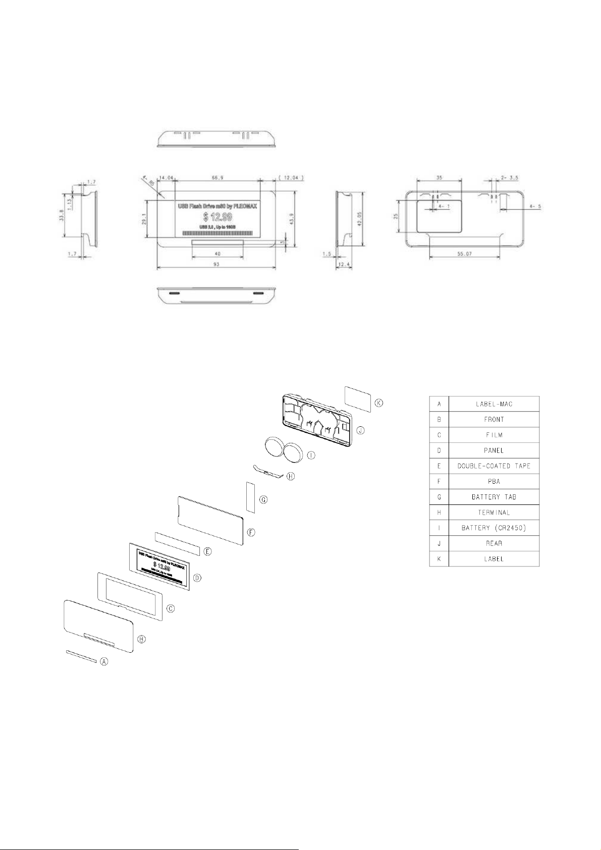
Physical Dimension(mm)
1.4
Exploded View of EPD TAG
1.5
Specifications
2.
Product
2.1
Item Description
Size
Battery
Display EPD PANEL display(Graphic type)
Information display Price, Unit, Discount, etc.
Communication IEEE802.15.4
Distance Radius
Operation Temp.
Etc. No additional anti-theft locking structure:Rail Mounted only
Radio(RF)
2.2
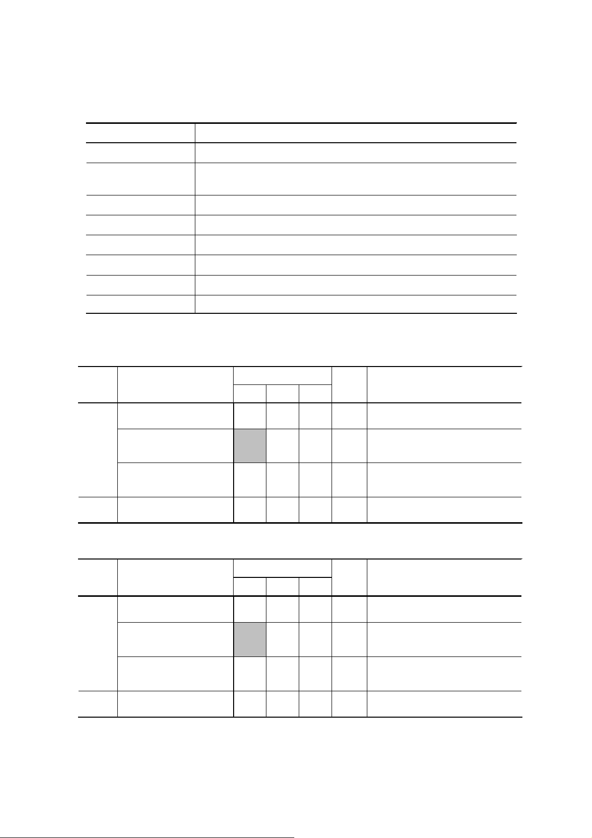
R&D Characteristic&OQC
2.2.1
Items Parameter
Transmit Power
Error Vector
TX
Magnitude
2.4 ~ 3.3
Min Typ Max
-5 0 8
93.0 x 43.9 x 12.4
CR2450 Lithium Battery(3V,2ea)
Vdc(condtion:In active status)
GHz ISM Band
2.4
20m (
spec.
10 30 %
Indoor, Line of Sight)
5 ~ 40
Units Condition
dBm
mm
MHz
(2400
℃
When measured for
chips
~ 2500
MHz)
100
Tx Current
RX Receiver Sensitivity
Production Characteristic
2.2.2
Items Parameter
Transmit Power
Error Vector
TX
RX Receiver Sensitivity
Test Channel
*
The contents in the grayed cells are not necessary to manage by Cpk.
*
Magnitude
Tx Current
: 2480
RX Test Channel can be changed according to the environment)
(
-90 - -
spec.
Min Typ Max
-3 0 8
10 28 %
-90 - -
MHz
- 40
- 37
Total current at max Tx
mA
Power
dBm PER
Units Condition
dBm
When measured for
chips
Total current at max Tx
mA
Power
dBm PER
< 1%
< 1%
100
 Loading...