

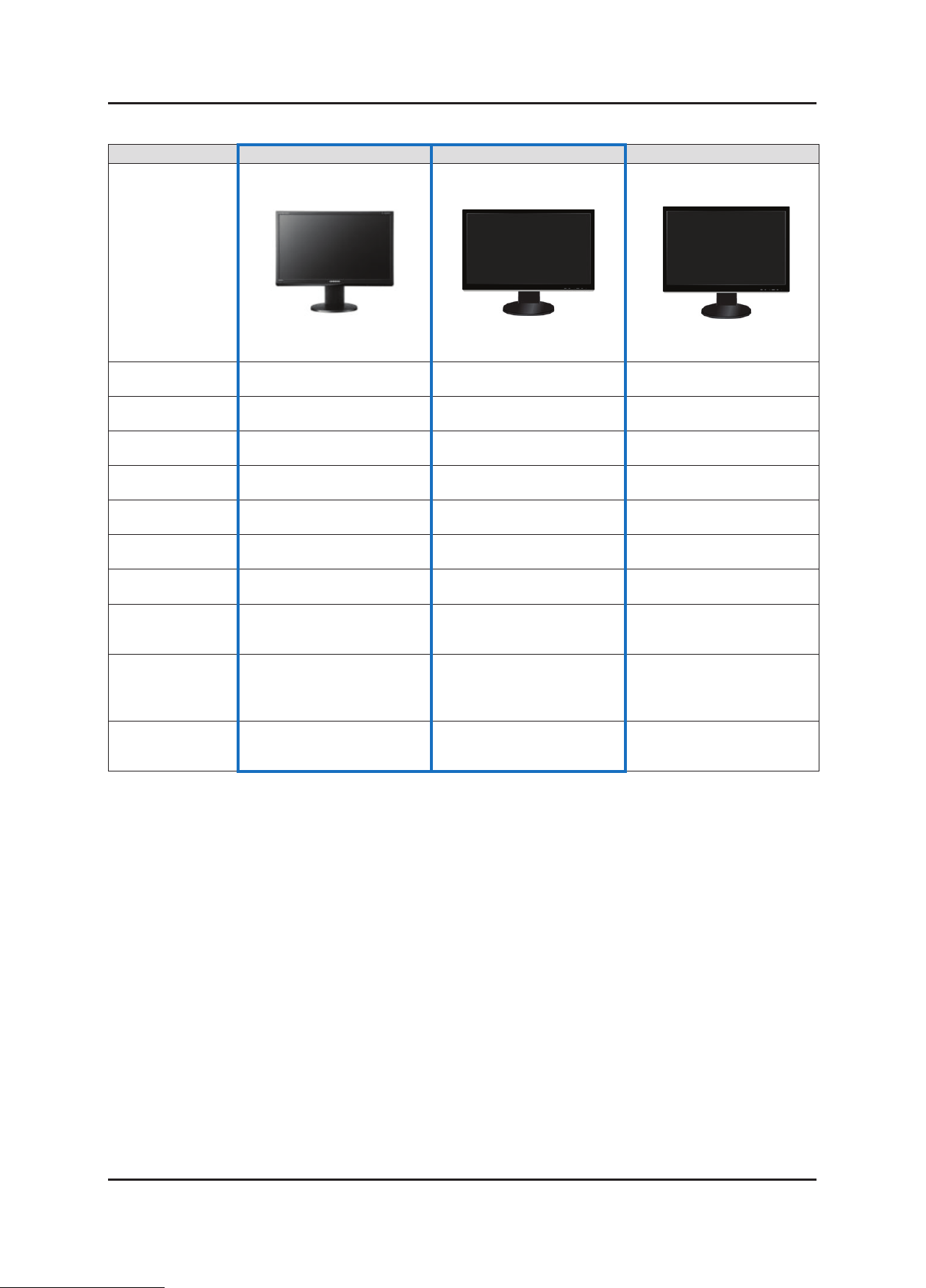
LCD-Monitor
Chassis : LS24KI
Model : 2494HS
2494HSI
2494HM
Manual
SERVICE
TFT-LCD Monitor Contents
1. Precautions
2. Product specications
3. Disassembly and Reassemble
4. Troubleshooting
5. Exploded View & Part List
6. Wiring Diagram
7. Schematic Diagram
2494HS / 2494HSI / 2494HM
Refer to the service manual in the GSPN (see the rear cover) for the more information.

Contents
1. Precautions .............................................................................................................. 1-1
1-1. Safety Precautions ......................................................................................................... 1-1
1-2. Servicing Precautions ..................................................................................................... 1-2
1-3. Static Electricity Precautions .......................................................................................... 1-2
1-4. Installation Precautions .................................................................................................. 1-3
2. Product specications ............................................................................................ 2-1
2-1. Feature & Specications ................................................................................................. 2-1
2-2. Spec Comparison to the Old Models .............................................................................. 2-2
2-3. Accessories .................................................................................................................... 2-3
2-4. Accessories (Sold separately) ........................................................................................ 2-3
3. Disassembly and Reassemble ............................................................................... 3-1
3-1. Disassembly (2494HS) ................................................................................................... 3-1
3-2. Disassembly (2494HS) ................................................................................................... 3-3
4. Troubleshooting ...................................................................................................... 4-1
4-1. Troubleshooting .............................................................................................................. 4-1
4-2. When the Power Does Not Turn On ............................................................................... 4-2
4-3. When a blank screen is displayed (Analog) ................................................................... 4-4
4-4. When a Blank Screen Is Displayed (DVI) ...................................................................... 4-7
4-5. Error Examples and Actions ......................................................................................... 4-10
4-6. Adjustment .................................................................................................................... 4-11
5. Exploded View & Part List ...................................................................................... 5-1
5-1. Exploded View (2494HS) ................................................................................................ 5-1
5-2. Parts List (2494HS) ........................................................................................................ 5-3
5-3. Exploded View (2494HM) ............................................................................................. 5-15
5-4. Parts List (2494HM) ...................................................................................................... 5-17
6. Wiring Diagram ........................................................................................................ 6-1
6-1. Wiring Diagram - Main Board ......................................................................................... 6-1
6-2. Wiring Diagram ............................................................................................................... 6-2
6-3. Connector Functions ...................................................................................................... 6-3
6-4. Cables ............................................................................................................................ 6-3
7. Schematic Diagram ................................................................................................. 7-1
7-1. Circuit Descriptions ......................................................................................................... 7-1
7-2. Schematic Diagram ....................................................................................................... 7-3
GSPN (Global Service Partner Network)
Area Web Site
North America http://service.samsungportal.com
Latin America http://latin.samsungportal.com
CIS http://cis.samsungportal.com
Europe http://europe.samsungportal.com
China http://china.samsungportal.com
Asia http://asia.samsungportal.com
Mideast & Africa http://mea.samsungportal.com
This Service Manual is a property of Samsung Electronics Co.,Ltd.
Any unauthorized use of Manual can be punished under applicable
International and/or domestic law.
© 2008 Samsung Electronics Co.,Ltd.
All rights reserved.
Printed in Korea
P/N: BN82-00507A-01
1. Precautions
1. Precautions
1-1. Safety Precautions
Follow these safety, servicing and ESD precautions to prevent damage and to protect against potential hazards such as
electrical shock.
1-1-1. Warnings
1.
For continued safety, do not attempt to modify the circuit board.
2.
Disconnect the AC power and DC power jack before servicing.
1-1-2. Servicing the LCD Monitor
1.
When servicing the LCD Monitor, Disconnect the AC line cord from the AC outlet.
2.
It is essential that service technicians have an accurate voltage meter available at all times. Check the calibration of
this meter periodically.
1-1-3. Fire and Shock Hazard
Before returning the monitor to the user, perform the following safety checks:
1.
Inspect each lead dress to make certain that the leads are not pinched or that hardware is not lodged between the
chassis and other metal parts in the monitor.
2.
Inspect all protective devices such as nonmetallic control knobs, insulating materials, cabinet backs, adjustment and
compartment covers or shields, isolation resistorcapacitor networks, mechanical insulators, etc.
3.
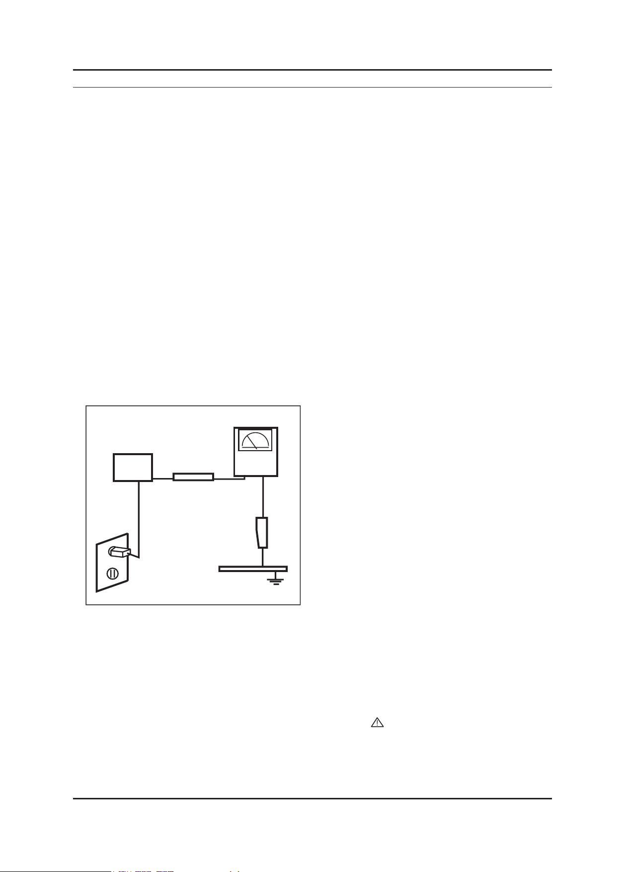
Leakage Current Hot Check (Figure 1-1):
WARNING : Do not use an isolation transformer during this test.
Use a leakage current tester or a metering system that complies with American National Standards Institute (ANSI
C101.1, Leakage Current for Appliances), and Underwriters Laboratories (UL Publication UL1410, 59.7).
(READING SHOULD)
NOT BE ABOVE 0.5mA
DEVICE
UNDER
TEST
TEST ALL
EXPOSED METAL
SURFACES
2-WIRE CORD
*ALSO TEST WITH
PLUG REVERSED
(USING AC ADAPTER
PLUG AS REQUIRED)
4.
With the unit completely reassembled, plug the AC line cord directly into a 120V AC outlet. With the unit’s AC switch
LEAKAGE
CURRENT
TESTER
EARTH
GROUND
Figure 1-1. Leakage Current Test Circuit
rst in the ON position and then OFF, measure the current between a known earth ground (metal water pipe, conduit,
etc.) and all exposed metal parts, including: metal cabinets, screwheads and control shafts.
The current measured should not exceed 0.5 milliamp.
Reverse the power-plug prongs in the AC outlet and repeat the test.
1-1-4. Product Safety Notices
Some electrical and mechanical parts have special safetyrelated characteristics which are often not evident from visual
inspection. The protection they give may not be obtained by replacing them with components rated for higher voltage,
wattage, etc. Parts that have special safety characteristics are identied by on schematics and parts lists. A substitute
replacement that does not have the same safety characteristics as the recommended replacement part might create
shock, re and/or other hazards. Product safety is under review continuously and new instructions are issued whenever
appropriate.
1-1

1-2
1. Precautions
1-2. Servicing Precautions
WARNING: An electrolytic capacitor installed with the wrong polarity might explode.
Caution: Before servicing units covered by this service manual, read and follow the Safety Precautions section of
this manual.
Note: If unforeseen circumstances create conict between the following servicing precautions and any of the
safety precautions, always follow the safety precautions.
1-2-1 General Servicing Precautions
1.
Always unplug the unit’s AC power cord from the AC power source and disconnect the DC Power Jack before
attempting to:
(a) remove or reinstall any component or assembly, (b) disconnect PCB plugs or connectors, (c) connect a test
component in parallel with an electrolytic capacitor.
2.
Some components are raised above the printed circuit board for safety. An insulation tube or tape is sometimes
used. The internal wiring is sometimes clamped to prevent contact with thermally hot components. Reinstall all such
elements to their original position.
3.
After servicing, always check that the screws, components and wiring have been correctly reinstalled. Make sure that
the area around the serviced part has not been damaged.
4.
Check the insulation between the blades of the AC plug and accessible conductive parts (examples: metal panels,
input terminals and earphone jacks).
5.
Insulation Checking Procedure: Disconnect the power cord from the AC source and turn the power switch ON.
Connect an insulation resistance meter (500 V) to theblades of the AC plug.
The insulation resistance between each blade of the AC plug and accessible conductive parts (see above) should be
greater than 1 megohm.
6.
Always connect a test instrument’s ground lead to the instrument chassis ground before connecting the positive lead;
always remove the instrument’s ground lead last.
1-3. Static Electricity Precautions
Some semiconductor (solid state) devices can be easily damaged by static electricity. Such components are commonly
called Electrostatically Sensitive Devices (ESD). Examples of typical ESD are integrated circuits and some eld-effect
transistors. The following techniques will reduce the incidence of component damage caused by static electricity.
1.
Immediately before handling any semiconductor components or assemblies, drain the electrostatic charge from your
body by touching a known earth ground. Alternatively, wear a discharging wrist-strap device. To avoid a shock hazard,
be sure to remove the wrist strap before applying power to the monitor.
2.
After removing an ESD-equipped assembly, place it on a conductive surface such as aluminum foil to prevent
accumulation of an electrostatic charge.
3.
Do not use freon-propelled chemicals. These can generate electrical charges sufcient to damage ESDs.
4.
Use only a grounded-tip soldering iron to solder or desolder ESDs.
5.
Use only an anti-static solder removal device. Some solder removal devices not classied as “anti-static” can generate
electrical charges sufcient to damage ESDs.
6.
Do not remove a replacement ESD from its protective package until you are ready to install it. Most replacement ESDs
are packaged with leads that are electrically shorted together by conductive foam, aluminum foil or other conductive
materials.
7.
Immediately before removing the protective material from the leads of a replacement ESD, touch the protective
material to the chassis or circuit assembly into which the device will be installed.
Caution: Be sure no power is applied to the chassis or circuit and observe all other safety precautions.
8.
Minimize body motions when handling unpackaged replacement ESDs. Motions such as brushing clothes together,
or lifting your foot from a carpeted oor can generate enough static electricity to damage an ESD.

1-3
1. Precautions
1-4. Installation Precautions
For safety reasons, more than two people are required for carrying the product.
1.
Keep the power cord away from any heat emitting devices, as a melted covering may cause re or electric shock.
2.
Do not place the product in areas with poor ventilation such as a bookshelf or closet. The increased internal
3.
temperature may cause re.
Make sure to turn the power off and unplug the power cord from the outlet before repositioning the product. Also check
4.
the antenna cable or the external connectors if they are fully unplugged. Damage to the cord may cause re or electric
shock.
Keep the antenna far away from any high-voltage cables and install it rmly. Contact with the highvoltage cable or the
5.
antenna falling over may cause re or electric shock.
When installing the product, leave enough space (10cm) between the product and the wall for ventilation purposes.
6.
A rise in temperature within the product may cause re.

1. Precautions
Memo
1-4
2. Product specications
2-1. Feature & Specications
Model 2494HS / 2494HSI / 2494HM
Support PC / DVI / HDMI
�
DC DC 50000:1 Applied
�
Adopted two 3W speakers.
�
USB (1 up, 2 down) optional
�
HDCP Applied for HDMI/DVI-D Fixed Aspect Ratio Support
�
Supports xed horizontal and vertical ratios
�
Supported camera effects: Black/Sepia/Green/Blue
�
Supports the Off-timer function
�
Item Description
Model 2494HS / 2494HSI 2494HM
2. Product specications
Feature
Specications
LCD Panel TFT-LCD panel, RGB vertical stripe,
normally black transmissive,
23.6-Inch viewable, 0.2715(H)x0.2715(V)
mm pixel pitch
Scanning Frequency Horizontal: 30 kHz ~ 81 kHz (Automatic)
Vertical: 56 Hz ~ 60 Hz
Maximum Resolution Horizontal: 1920 Pixels
Vertical: 1080 Pxels
Input Signal
Input Sync Signal Seperate H/V sync, Composite:
Maximum Pixel Clock Rate
Active Display Horizontal/Vertica
AC Power Voltage & Frequency AC 90~264V Volts, 60/50Hz
Power Consumption Less than 48W Less than 48W
Dimensions ( W X H X D) 572.8 x 227.4 x 420.4 mm (With Stand)
PC/DVI/HDMI
automatic synchronization without external switch
Level : TTL level (V high ≥ 2.0V, V low ≤ 0.8V)
164MHz
l 521.28(H) x 293.22(V) mm 531.36(H) x 298.89(V) mm
572.8 x 67.5 x 363.4 mm (Without Stand)
TFT-LCD panel, RGB vertical stripe,
normally black transmissive,
24-Inch viewable, 0.2768(H)x0.2768(V)
mm pixel pitch
572.8 x 249.9 x 420.4 mm (With Stand)
572.8 x 67.5 x 363.7 mm (Without Stand)
Weight
Environmental
Considerations
Note: Designs and specications are subject to change without prior notice..
Products: 6.2 kg Products: 8.4 kg
Operating Temperature: 10˚C ~ 40˚C(50˚F ~ 104˚F)
Operating Humidity: 10% ~ 80%
Storage temperature: -20˚C ~ 45˚C(-4˚F ~ 113˚F)
Storage Humidity: 5% ~ 95%
2-1
2-2
2. Product specications
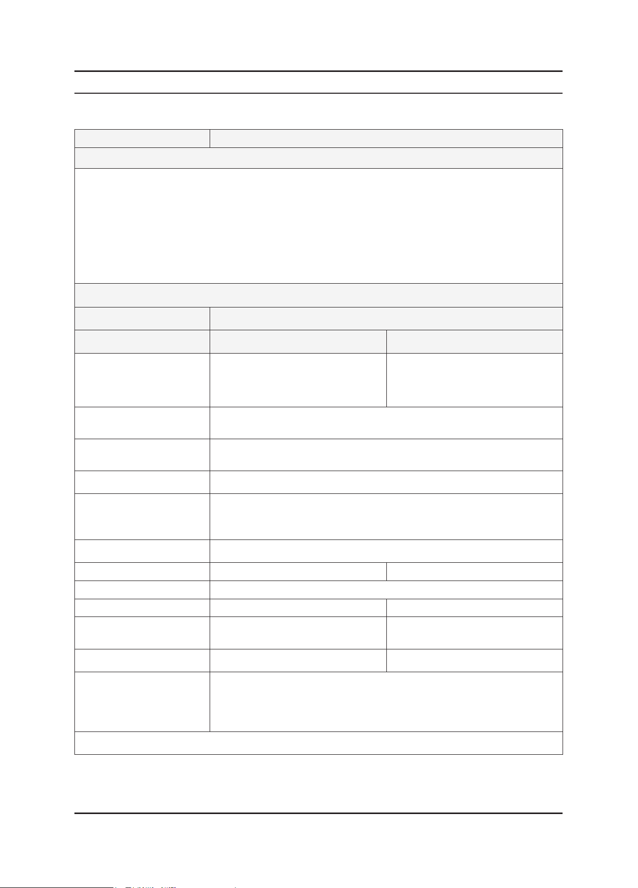
2-2. Spec Comparison to the Old Models
Model 2494HS / 2494HSI 2494HM 2493HM
Design
Screen Size 23.6” 24” 24”
Display Size 16:9 16:9 16:10
Brightness 300cd/m2 300cd/m2 400cd/m2
Dynamic CR 50000:1 50000:1 10000:1
Input Source Analog/Digital/HDMI Analog/Digital/HDMI Analog/Digital/HDMI
Speaker 3Wx2 3Wx2 2Wx2
Magictune Premium Premium Premium
Gamma
MagicBright
Color Tone
3 steps
Mode1 / Mode2 / Mode3
7 steps (Text / Internet / Game
/ Sports / Movie / Dynamic CR /
Custom)
4 Step
Cool / Normal / Warm / Custom
Mode1 / Mode2 / Mode3
7 steps (Text / Internet / Game
/ Sports / Movie / Dynamic CR /
Cool / Normal / Warm / Custom
3 steps
Custom)
4 Step
3 steps
Mode1 / Mode2 / Mode3
7 steps (Text / Internet / Game
/ Sports / Movie / Dynamic CR /
Custom)
4 Step
Cool / Normal / Warm / Custom
2-3
2. Product specications
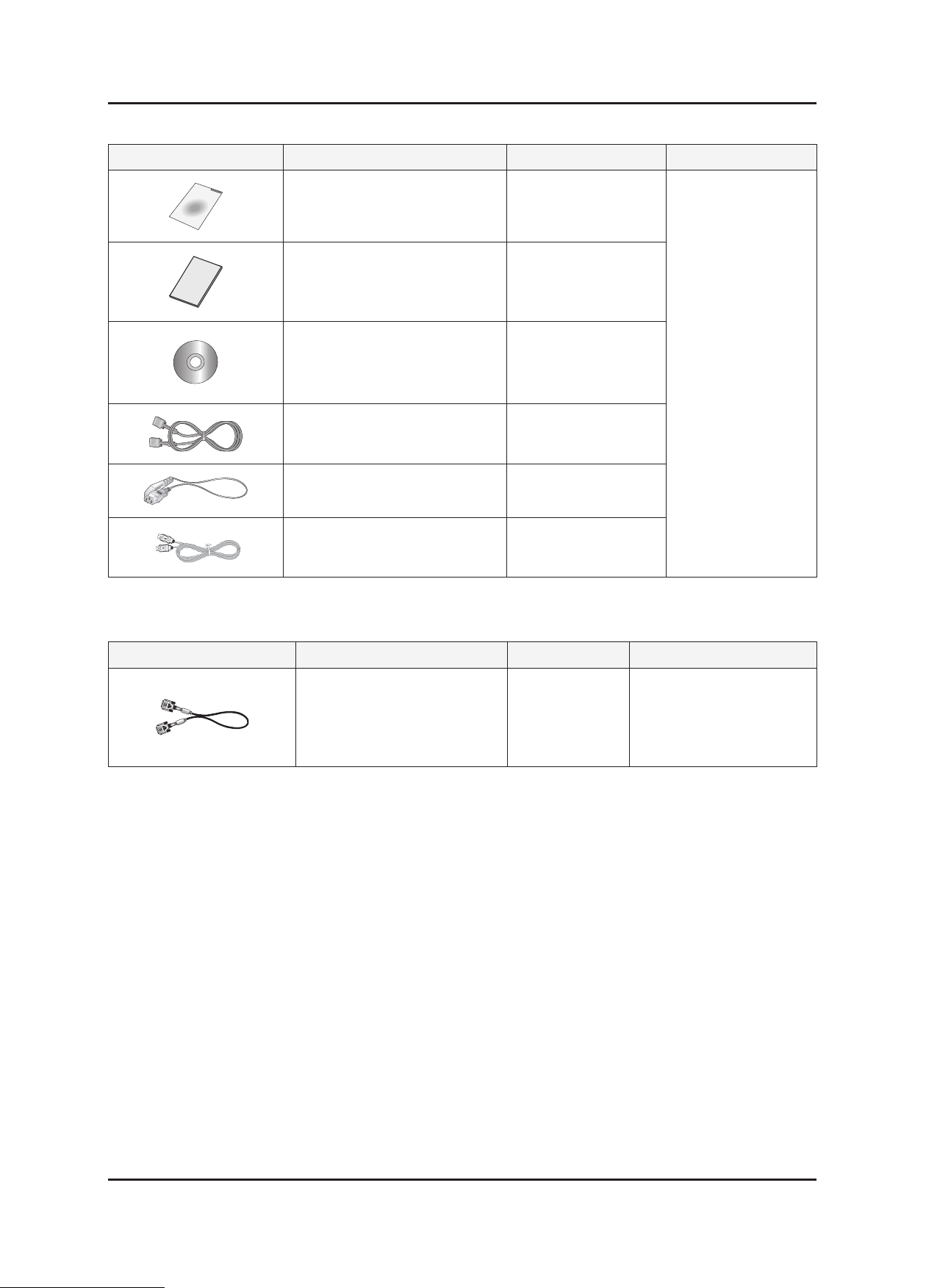
2-3. Accessories
Product Description Ccde. No Remark
Quick Setup Guide BH68-00174P
Warranty Card
(Not available in all locations)
User’s Guide,
Monitor Driver,
Natural Color software,
MagicTune™ software
D-Sub(15 Pin) Cable
(Shipped as assembled with the set)
Power Cord 3903-00212
USB Cable(USB HAS stand only) BN39-00397C
2-4. Accessories (Sold separately)
Product Description Ccde. No Remark
BH68-01146A
BN59-00660F
BN39-00244G
Samsung Electronics
Service center
DVI Cable BN39-00246K
Samsung Electronics
Service center

2. Product specications
Memo
2-4
3. Disassembly and Reassemble
3. Disassembly and Reassemble
This section describes the disassembly and reassembly sequences for this monitor.
WARNING: As this monitor has parts that are sensitive to static electricity, be careful when handling them.
3-1. Disassembly (2494HS / 2494HSI)
Cautions: 1. Turn the monitor off before beginning the disassembly process.
2. Disassemble the monitor carefully as directed in the following procedures.
3. When disassembling the monitor, do not use any metal tools except for the provided jig.
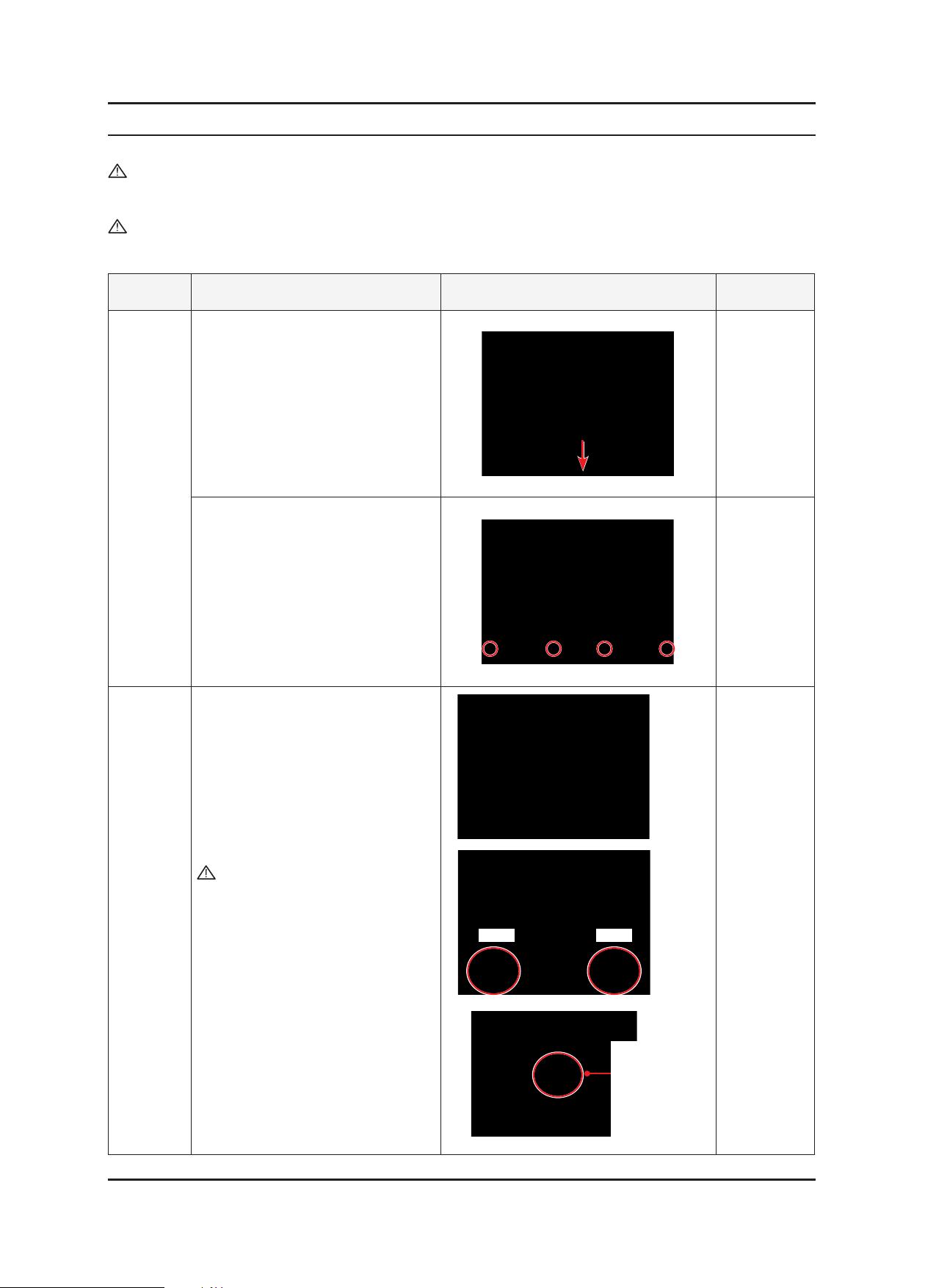
Part Description Picture Description Screws
1. Place a soft cloth on the table and
place the monitor on it so the front
part is facing downwards. Hold and
pull the stand downwards to remove it
from the monitor set.
Stand
Rear cover
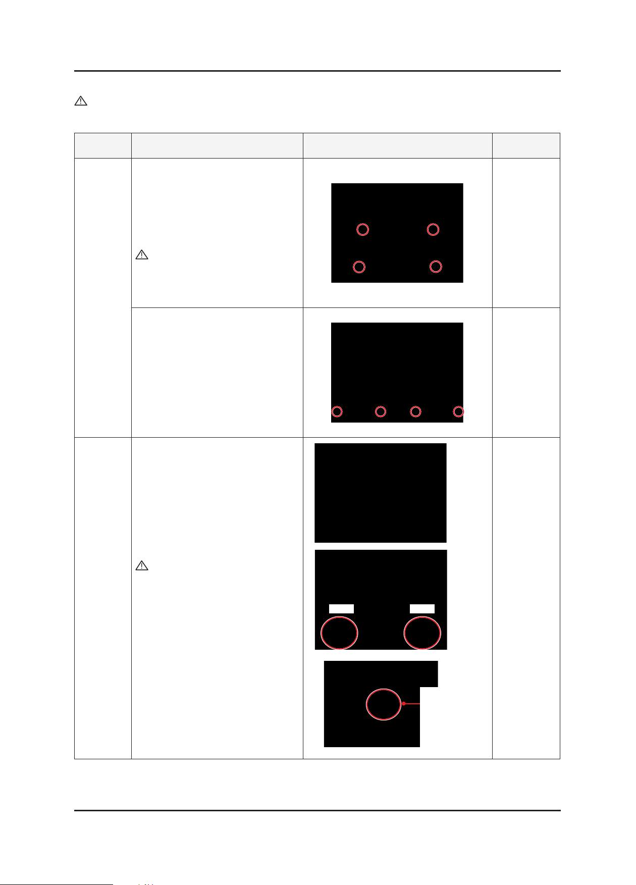
2. Remove the four (4) screws on the
bottom, as shown in the gure on the
right.
3. Hold the projected part of the rear
cover with one hand, hold the front
cover with the other hand, and
then lift and remove the rear cover
upwards.
Caution : If you remove the rear
cover by holding and lifting
the red circle part marked
with ‘NO’ upwards (to the
left of the gure on the
right), a crack may occur
on the Function-PCB
connector. Make sure to
hold and lift the red circle
part marked with ‘YES’
upwards (to the right of
the gure on the right), to
remove the rear cover.
YESNO
If handled
incorrectly,
a crack may
occur on the
Function-PCB
connector.
3-1
3-2
3. Disassembly and Reassemble
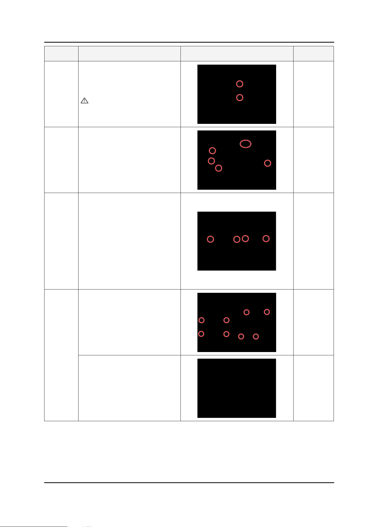
Part Description Picture Description Screws
4. Remove the shield lamp using a at
SHIELD-
LAMP
screwdriver or the provided jig.
Caution : Be careful because the
shield lamp is sharp.
Removing
the cables
ASSY
CHASSIS
5. Remove the lamp wire, function wire,
speaker connector, and LVDS cable
connected to the chassis.
6. Remove the four (4) hex screws on
the bottom of the shield, as shown in
the gure on the right.
7. Remove the eight (8) screws
designated in the gure on the right,
lift the boards upwards and remove
the cable shown in the gure on the
right.
BOARD,
IP-Board
MAIN
8. Remove the main board and IP-board
from the shield cover.
3-3
3. Disassembly and Reassemble
3-2. Disassembly (2494HS)
Cautions: 1. Turn the monitor off before beginning the disassembly process.
2. Disassemble the monitor carefully as directed in the following procedures.
3. When disassembling the monitor, do not use any metal tools except for the provided jig.
Part Description Picture Description Screws
1. Place a soft cloth on the table and
place the monitor on it so the front
part is facing downwards.
Remove the four (4) screws
designated in the gure on the right
and remove the stand.
Caution : When removing the screws,
make sure to hold the stand
body with one hand so that
the stand does not fall over.
Stand
Rear Cover
2. Remove the four (4) screws on the
bottom, as shown in the gure on the
right.
3. Hold the projected part of the rear
cover with one hand, hold the front
cover with the other hand, and
then lift and remove the rear cover
upwards.
Caution : If you remove the rear
cover by holding and lifting
the red circle part marked
with ‘NO’ upwards (to the
left of the gure on the
right), a crack may occur
on the Function-PCB
connector. Make sure to
hold and lift the red circle
part marked with ‘YES’
upwards (to the right of the
right gure) to remove the
rear cover.
YESNO
If handled
incorrectly,
a crack may
occur on the
Function-PCB
connector.

3. Disassembly and Reassemble
Part Description Picture Description Screws
4. Remove the shield lamp using a at
SHIELD-
LAMP
screwdriver or the provided jig.
Caution : Be careful because the
shield lamp is sharp.
Removing
the cables
ASSY
CHASSIS
MAIN
BOARD,
IP-Board
5. Remove the lamp wire, function wire,
speaker connector, and LVDS cable
connected to the chassis.
6. Remove the four (4) hex screws on
the bottom of the shield, as shown in
the right gure.
7. Remove the eight (8) screws
designated in the right gure, lift the
boards upward and remove the cable
shown in the gure on the right.
8. Remove the main board and IP-board
from the shield cover.
※Reassembly procedures are in the reverse order of disassembly procedures.
3-4

4. Troubleshooting
4-1. Troubleshooting
1.
Before troubleshooting, setup the PC ‘s display as below.
• Resolution: 1920 x 1080
• H-frequency: 75 kHz
• V-frequency: 60 Hz
2.
If no picture appears, make sure the power cord is correctly connected.
3.
Check the following circuits.
• No raster appears: Function PBA. Main PBA. IP-Board
• 5V develop but no screen : Main PBA
• 13V, 5V does not develop: IP-Board, Main PBA
4. Troubleshooting
4-1

4-2
4. Troubleshooting
4-2. When the Power Does Not Turn On
The LED on the front panel of the monitor does not work when the power is connected and the
Symptom
Major checkpoints
-
Power button is pressed.
Check if the Power switch on the rear panel of the monitor has been turned on.
-
Check the SMPS fuse and the IP-Board output power.
-
Check the connection between the IP-Board and the Main Board inside the monitor.
-
Check the power part of the Main Board and check if a similar symptom appears at another
-
output terminal.
CN600
IC203
Main Board Front
Diagnostics
Check the connection status of the
Function assy.
Can DC 5V be measured on pins 6, 7
of the CN600 connector when pins 3, 4,
and 5 are 0V?
Yes
Can DC 3.3V be measured on pin 3 of
the IC203 when pin 1 is DC 5V?
Yes
Check and replace the main board
related to the scaler.
Caution Make sure to disconnect the power before working on the IP board.
No
No
Replace the IP board.
Check the circuits related to
the IC203.
4-3
4. Troubleshooting
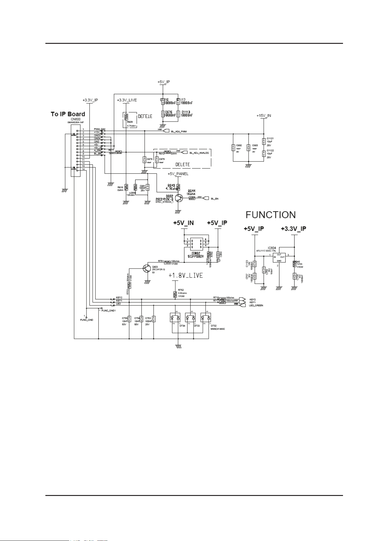
4-2-1. Circuit Diagram and Waveform for Power Failures
 Loading...