

SAMSUNG 245B Service Manual

SERVICE
Manual
LCD Monitor
Fashion Feature
LCD-Monitor
Chassis LHU24BS
Model 245B
245BW
- Magic Bright
- Magic Color
- Unified UI/function

ii
Copyright
©2007 by Samsung Electronics Co., Ltd.
All rights reserved.
This manual may not, in whole or in part, be copied,
photocopied, reproduced, translated, or converted to
any electronic or machine readable form without prior
written permission of Samsung Electronics Co., Ltd.
LHU24BS Service Manual
First edition March 2007.
Printed in Korea.
Trademarks
Samsung is the registered trademark of Samsung
Electronics Co., Ltd.
LHU24BS and MacMaster Cable Adapter are
trademarks of Samsung Electronics Co., Ltd.
Macintosh, Power Macintosh are trademarks of Apple
Computer, Inc.
All other trademarks are the property of their respective
owners.

11. Precautions
………………………………………………………………………………………………………………………………………
11-1
1-1 Safety Precautions ……………………………………………………………………………………………………………………… 1-1
1-2 Servicing Precautions …………………………………………………………………………………………………………………… 1-2
1-3 Electrostatically Sensitive Devices (ESD) Precautions ……………………………………………………………………………… 1-2
1-4 Installation Precautions ………………………………………………………………………………………………………………… 1-3
2
2. Product specifications
…………………………………………………………………………………………………………………………
22-1
2-1 Fashion Feature…………………………………………………………………………………………………………………………… 2-1
2-2 Feature …………………………………………………………………………………………………………………………………… 2-1
2-3 Specifications ……………………………………………………………………………………………………………………………… 2-2
2-4 Spec Comparison ………………………………………………………………………………………………………………………… 2-3
2-5 Option Specification ……………………………………………………………………………………………………………………… 2-4
3
3. Alignments and Adjustments
…………………………………………………………………………………………………………………
33-1
3-1 Required Equipment …………………………………………………………………………………………………………………… 3-1
3-2 Automatic Color Adjustment …………………………………………………………………………………………………………… 3-1
3-3 OSD Adjustment When Replacing Panel ……………………………………………………………………………………………… 3-1
3-4 OSD Adjustment When Replacing Panel ……………………………………………………………………………………………… 3-1
3-5 OSD Adjustment When Replacing Lamp Only ………………………………………………………………………………………… 3-1
3-6 Service Function Spec. ……………………………………………………………………………………………………………………3-2
3-7 Hidden Key list ……………………………………………………………………………………………………………………………3-3
3-8 DDC Input Method(Windows Program) …………………………………………………………………………………………………3-4
4
4. Troubleshooting
…………………………………………………………………………………………………………………………………
44-1
4-1 No Power ……………………………………………………………………………………………………………………………………4-1
4-2 No Video (PC Analog Signal) …………………………………………………………………………………………………………… 4-3
4-3 No Video (PC Digital Signal) …………………………………………………………………………………………………………… 4-5
5
5. Exploded View and Parts List
………………………………………………………………………………………………………………
55-1
6. EElectrical Parts List
……………………………………………………………………………………………………………………………
66-1
7. BBlock Diagram
…………………………………………………………………………………………………………………………………
77-1
Contents

88. Wiring Diagram
…………………………………………………………………………………………………………………………………
88-1
9. SSchematic Diagrams
……………………………………………………………………………………………………………………………
99-1
9-1 Schematic Diagrams ……………………………………………………………………………………………………………………… 9-1
1
10. Operating Instructions and Installation ………………………………………………………………………………………………………10-1
10-1 Front …………………………………………………………………………………………………………………………………… 10-1
10-2 Rear
………………………………………………………………………………………………………………………………………10-2
10-3 Using the Stand
…………………………………………………………………………………………………………………………10-4
1
11. Disassembly and Reassembly
………………………………………………………………………………………………………………
111-1
11-1 Disassembly …………………………………………………………………………………………………………………………… 11-1
11-2 Reassembly …………………………………………………………………………………………………………………………… 11-4
1
12. PCB Diagram
…………………………………………………………………………………………………………………………………
112-1
13. CCircuit Descriptions
……………………………………………………………………………………………………………………………
113-1
13-1 Block description ……………………………………………………………………………………………………………………… 13-1
1
14. Reference Infomation
………………………………………………………………………………………………………………………
114-1
14-1 Technical Terms ……………………………………………………………………………………………………………………… 14-1
14-2 Pin Assignments…………………………………………………………………………………………………………………………14-4
14-3 Timing Chart ……………………………………………………………………………………………………………………………14-5
14-4 Preset Timing Modes ………………………………………………………………………………………………………………… 14-6
14-5 Panel Description ……………………………………………………………………………………………………………………… 14-7
Contents

Samsung Electronics Co.,Ltd.
416, Maetan-3Dong, Yeongtong-Gu, Suwon City,
Gyeonggi-Do, Korea, 443-742
Printed in Korea
P/N : BN82-00169E-00
URL : http://itself.sec.samsung.co.kr/
-This Service Manual is a property of Samsung
Electronics Co., Ltd.
Any unauthorized use of Manual can be punished
under applicable International and/or domestic
law.
3-1 Required Equipment
The following equipment is necessary for adjusting the monitor:
- Computer with Windows 95, Windows 98, Windows 2000, Windows XP or Windows NT.
- MTI-2031 DDC MANAGER JIG
3-2 Automatic Color Adjustment
To input video, use 16 gray or any pattern using black and white.
1. Select english for OSD language.
2. Press the " (Enter/Source)" key for 5 seconds.
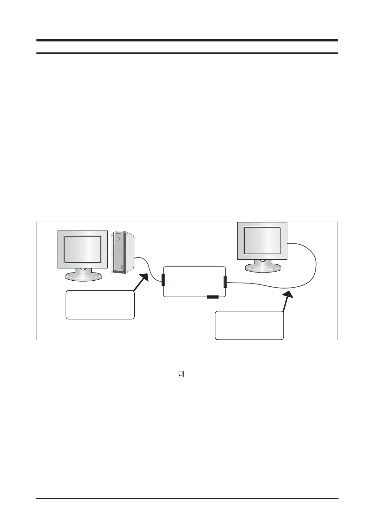
3-3 DDC EDID Data Input
1. Input DDC EDID data when replacing AD PCB.
2. Receive/Download the proper DDC file for the model from HQ quality control department.
Install the below jig (Figure 1) and enter the data.
3-4 OSD Adjustment When Replacing Panel
1. Adjust brightness and contrast to 0. Then, press the (Enter/Source) key for 5 second.
Service function OSD will appear on screen.
2. Press the + key to place the cursor on the panel. Press the menu key for 5 seconds.
3-5 OSD Adjustment When Replacing Lamp Only
1. Adjust brightness and contrast to 0. Then, press the exit key for 5 seconds.
Service function OSD will appear on the screen.
2. Press the + key. Select upper lamp and press the menu key for 5 seconds.
Then, select lower lamp and press the menu key for 5 seconds.
-Note : Please be sure to read the following instructions for details on service function.
3 Alignments and Adjustments
3-1
3 Alignments and Adjustments
This section of the service manual explains how to use the RS232 JIG.
This function is needed for AD board change.
Figure 1.
Parallel Connector
(25P Cable)
MTI-2031
DDC Manager
Connect Monitor
Signal Cable

3 Alignments and Adjustments
3-2
3-6 Ser vice Function Spec.
3-6-1 How to Display Service Function OSD
1. After setting both brightness and contrast to '0' push the 'enter' button more than
5 seconds.
2. service function appear as below.
3-6-2 How to Control Ser vice Function OSD
1. Monitor On Time : Power on time
2. Panel Cycle : Panel on/off time(Power off, mode change, DPMS on/off..)
3. Panel : Panel on time
(Each time the panel is replaced press the menu key for 5 seconds to add to the
Ch. No. indicating the number of time the panel has been changed.)
4. Upper lamp : Upper lamp on time
(When the upper lamp is replaced press menu to add to the Ch. No. which shows the number of times
the lamp has been replaced.)
5. Lower lamp : lower lamp on time
(When the upper lamp is replaced press menu to add to the Ch. No. which shows the number of times
the lamp has been replaced.)
6. Auto auto : If Auto auto menu set to on, when the mode is changed for the first time, Auto adjust function
is performed. Default is on
7. Pixel Shift : Not used
8. Country : OSD language can be changed with this menu to World wide, Korean, China, or Japanese.
You can navigate the menu with "+"key, and adjust with "menu key" pressing 5 seconds(Panel, Upper
Lamp, and Lower Lamp memu). You can also control Auto auto, Pixel Shift, and country menu with
pressing "-"key.
Figure 2.
3 Alignments and Adjustments
3-3
3-7 Hidden Key list
No
1. Hidden Service Function -. After setting brightness and contrast '0' push
the "Menu" button more than 5 seconds.
-. Service Function appear.
2. Factory Reset -. While Menu is opened(any menu), press "enter" key
over 5 seconds.
-. Screen is flashing, then all menus return to the
factory default.
3. Auto calibration To Analog video, In 16gray or any pattern using black and
white and any mode.(16gray and XGA mode recommend)
1. Push the OSD Menu button to open the OSD.
2. Select language English.
3. Push enter button during 5 seconds.
4. Screen is flashed and auto calibration is completed.
4. OSD lock -. Press the Menu key over 5 seconds, then OSD is locked .
-. To unlocked the OSD, press the Memu key over
5 seconds.
Function Action method
3 Alignments and Adjustments
3-4
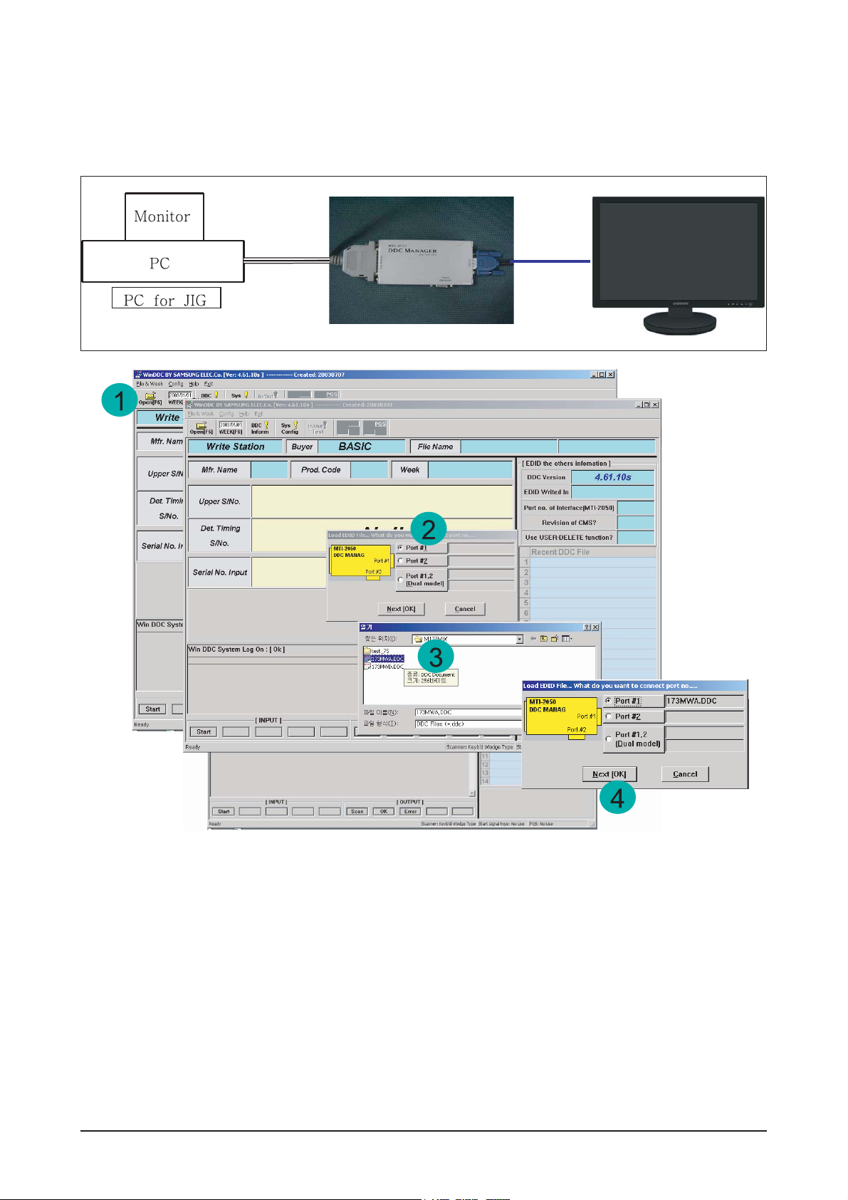
3-8 DDC Input Method(Windows Prog ram)
1. Winddc.exe Program install in PC
2. Cilck the Winddc icon.
3. File open.
4. Select Port#1
Load DDC fileFile Name
-. "SM245BA.DDC"
-. "SM245BD.DDC"
Click Next(OK) button.
After change a Main Board ,DDC input shpuld be done via DDC control JIG.
Connecting method is refer to below picture.
3 Alignments and Adjustments
3-5
3-8-1 Execution Items after replacing the main board
After Replacing the Maing Board
1. Auto Calibration
2. EDID installation(Analog and Digital)
3. Factory Reset
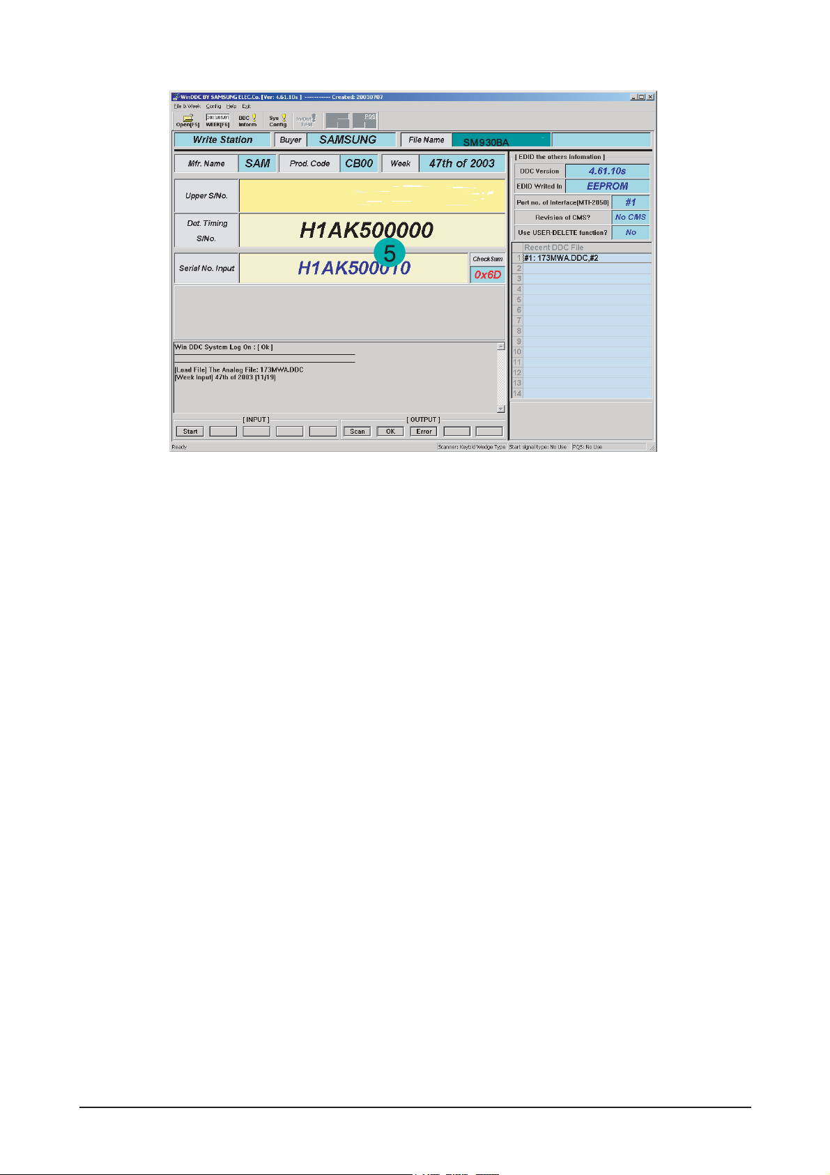
5: Input a monitor serial number and push the enter key.
After Analog input, Please do # 2 ~ 5 when digital input.

Memo
3 Alignments and Adjustments
3-6
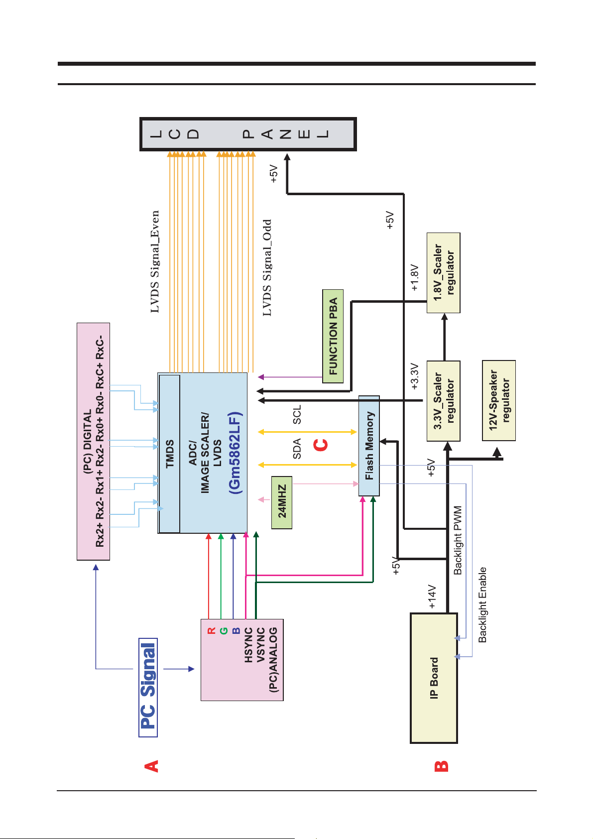
7 Block Diagrams
7-1
7 Block Diagram
7-1 Block Diagram

7 Block Diagrams
7-2
Memo
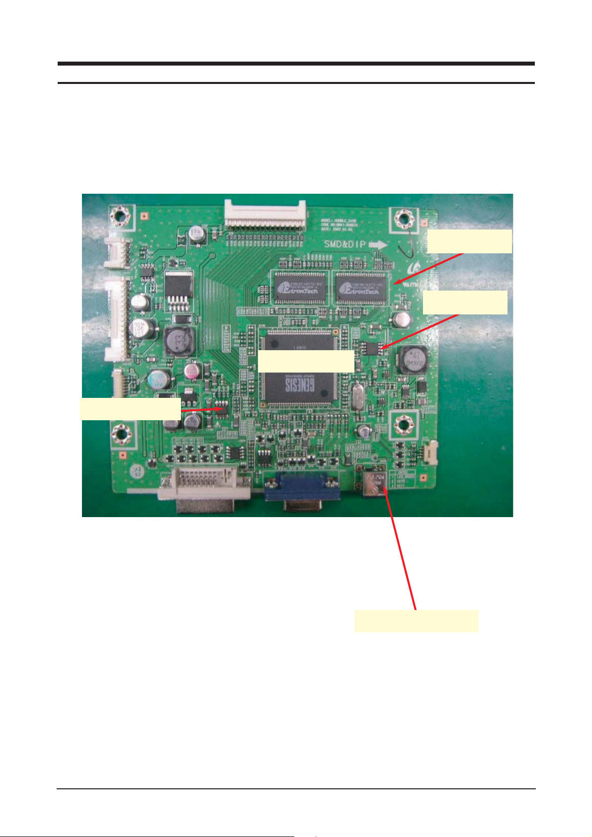
13 Circuit Descriptions
13-1
13 Circuit Descriptions
13-1 Block description
Speaker Jack
scaler
Flash memory
EEPROM -
NVRAM
S-DRAM

13 Circuit Descriptions
13-2
Memo
11 Disassembly and Reassembly
11-1
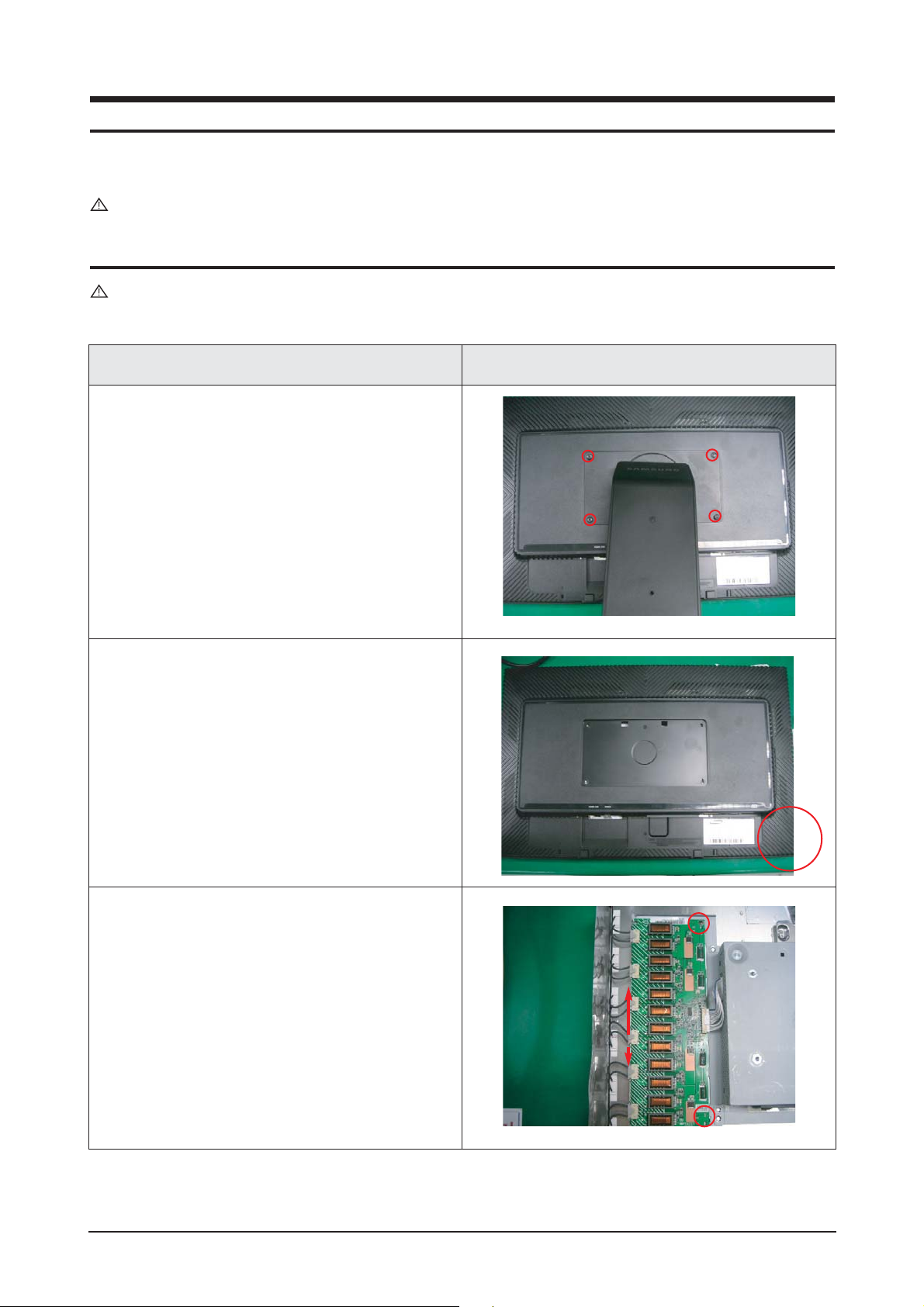
11 Disassembly and Reassembly
This section of the service manual describes the disassembly and reassembly procedures for the LHA20WS
TFT-LCD monitors.
WARNING: This monitor contains electrostatically sensitive devices. Use caution when handling
these components.
11-1 Disassembly
Cautions: 1. Disassembly stand on the flat desk.
2. Disconnect the monitor from the power source before disassembly.
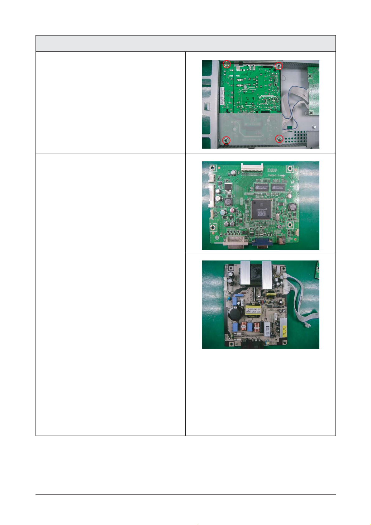
Description Picture Description
1. Put the monitor on the cushion .
Remove the 4 screws from the stand base .
2. Open the bottom of the rear cabinet use a Jig
3. Remove the 2 screws form the Inverter
11 Disassembly and Reassembly
11-2
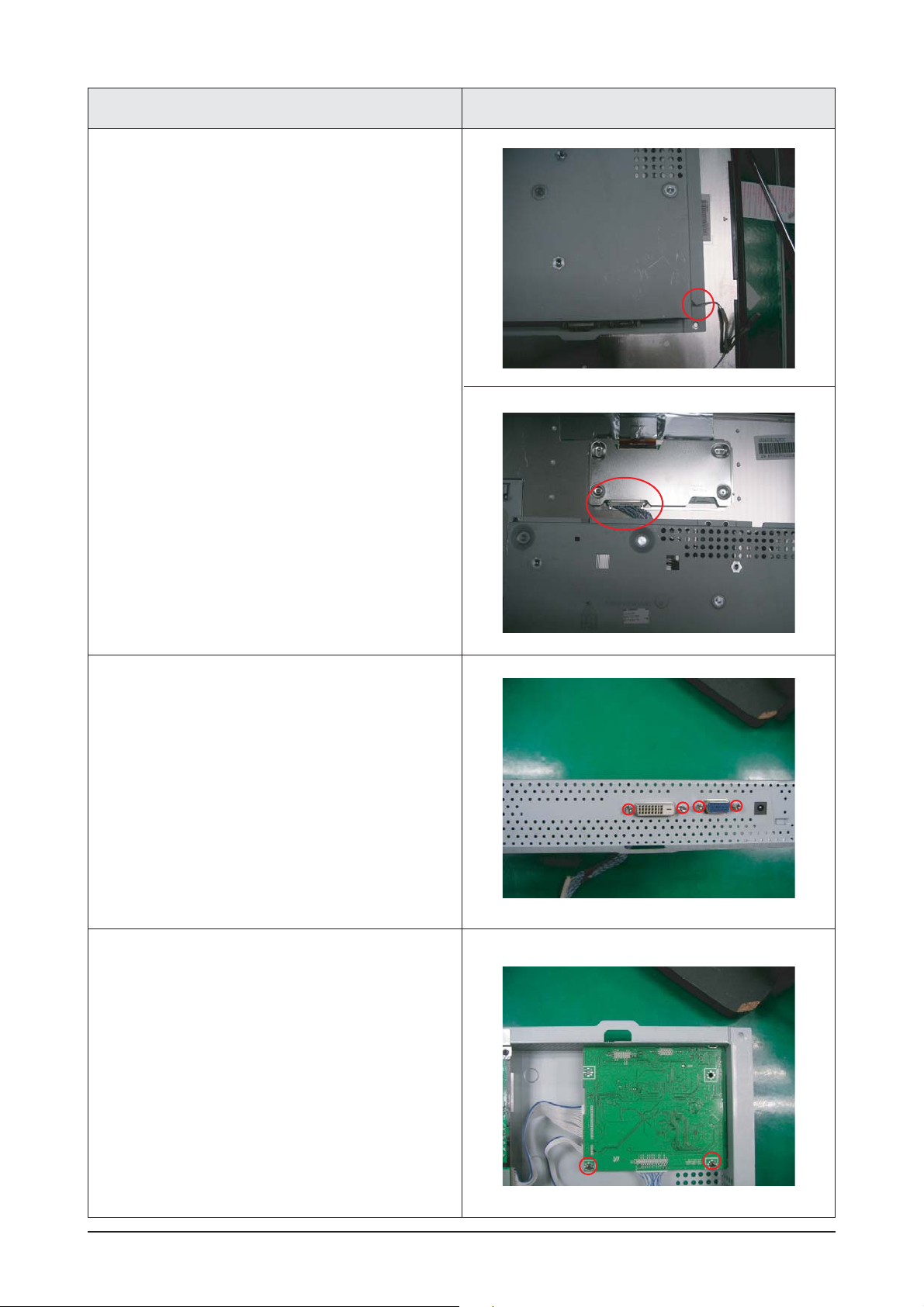
Description Picture Description
4. Remove the function wire form the PCB ASS'Y.
- Remove the function wire form the
PCB ASS'Y.
- Remove the LVDS Wire form the Panel.
5. Remove the 4 screws from the Shield cover and
Main , IP Board.
6. Remove the 2 screws from Main PBA
and then , disassemble the main board
11 Disassembly and Reassembly
11-3
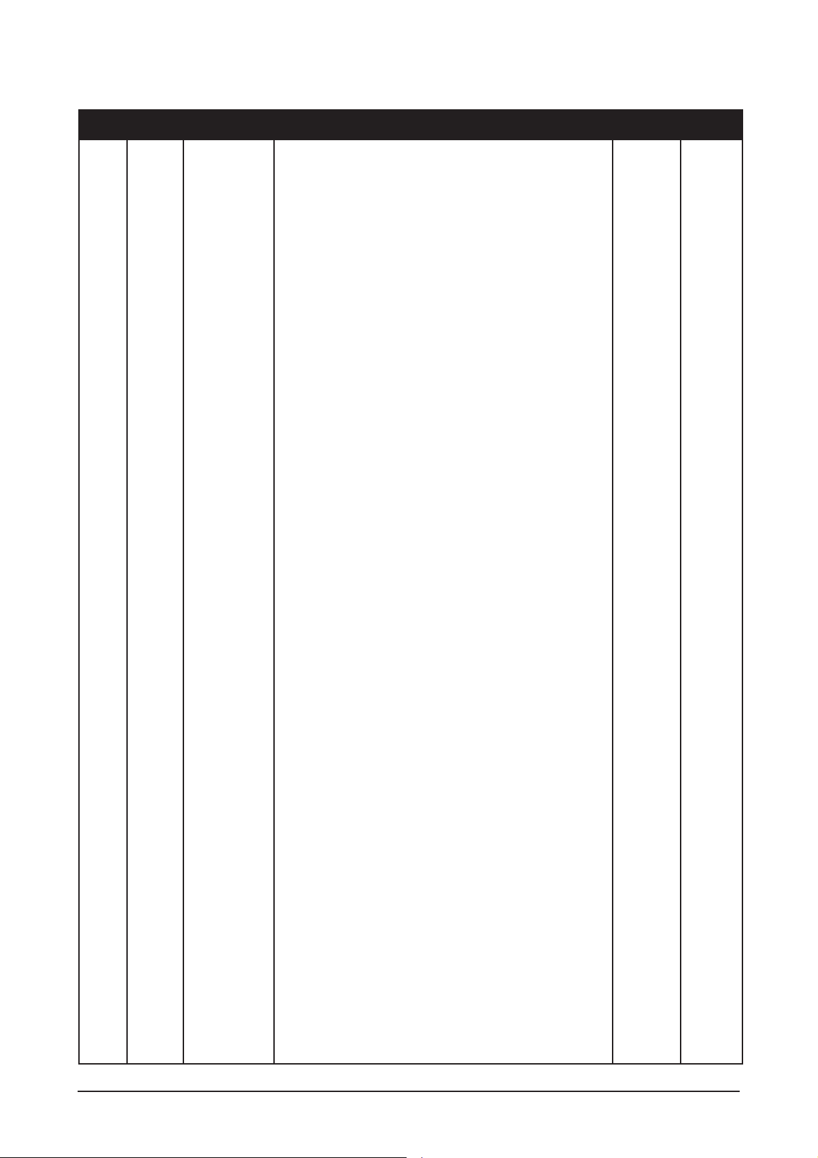
7. Remove the 4 screws from SMPS PBA
and then, disassemble the SMPS board.
8. This is the Completed disassemble board.
Description Picture Description

11 Disassembly and Reassembly
11-4
11-2 Reassembly
Reassembly procedures are in the reverse order of disassembly procedures.

6 Electrical Parts List
-You can search for updated part codes through ITSELF web site.
URL : http://itself.sec.samsung.co.kr/
6-1 LS24HUBCBQ/XAA Parts List
6 Electrical Parts List
6-1
Level Loc. No. Code No. Description & Specification Q'ty SA/SNA
LS24HUBCBQ/XAA 245B,WUG1/S24A4-LHU,24,LCD-MO,UNITED STA
0.1 M0001 BN90-01273A ASSY COVER FRONT;LS24HUBCBQ/EDC 1 S.N.A
..2 T0003 BN96-04912B ASSY COVER P-FRONT;LS24HU(245B),ABS HB,B 1 S.A
...3 M0112 BN63-03071B COVER-FRONT;LS24HU (245B),ABS HB,2.8,BLA 1 S.N.A
...3 T0054 BN64-00505A KNOB-DECORATION;HUBBLE,ABS HB,T2.0,NATUR 1 S.N.A
...3 T0022 BN64-00565A KNOB CONTROL;HUBBLE24",ABS HB,2.8,IV16,U 1 S.N.A
...3 M0145 BN96-05226A ASSY BOARD P-FUNCTION(DOME);HUBBLE 245B, 1 S.A
0.1 M0002 BN90-01274A ASSY COVER REAR;LS24HUBCBQ/EDC 1 S.N.A
..2 M0013 BN96-04914A ASSY COVER P-REAR;LS24HU (245B),ABS HB B 1 S.A
...3 BN61-03085A HOLDER-JACK;HUBBLE,ABS HB,BK26,245B 1 S.N.A
...3 M0006 BN63-03072A COVER-REAR;HUBBLE24",ABS HB,2.8,BK26 1 S.N.A
0.1 M0216 BN90-01275A ASSY STAND;LS24HUBCBQ/EDC 1 S.N.A
..2 M0003 BN96-04906A ASSY STAND P;HUBBLE,SECC,T2.0,245B 1 S.A
...3 T0081 6001-001547 SCREW-MACHINE;BH,+,M4,L10(5),ZPC(BLK),SW 4 S.A
...3 M0081 6003-000275 SCREW-TAPTITE;BH,+,-,B,M3,L10,ZPC(BLK),S 5 S.N.A
...3 M0081 6003-001119 SCREW-TAPTITE;FH,+,-,S,M4,L10,ZPC(BLK),S 12 S.N.A
...3 HC+CW 6009-001370 SCREW-SPECIAL;PWH,+,-,M4,L8,ZPC(WHT),SWR 1 S.N.A
...3 BN61-02634A GUIDE-STAND RETAINER;HUBBLE,ACETALl,T2.0 2 S.N.A
...3 BN61-02917A HOLDER-SWIVEL RING;HUBBLE24",ACETAL,2.8 1 S.N.A
...3 BN61-02919A GUIDE-STAND LIFT;HUBBLE24",ACETAL,2.8 1 S.N.A
...3 BN61-02920A BRACKET-STAND BOTTOM;HUBBLE24",SECC,2.0 1 S.N.A
...3 BN61-02921A BRACKET-STAND BODY;HUBBLE24",SECC,2.0,OU 1 S.N.A
...3 BN61-02922A BRACKET-STAND LIFT;HUBBLE24",SECC,2.0,IN 1 S.N.A
...3 BN61-02926A BRACKET-STAND BOTTOM;HUBBLE24",ALDC 1 S.N.A
...3 M0174 BN63-03074A COVER-STAND TOP;HUBBLE24",ABS HB,2.8,BK2 1 S.N.A
...3 BN63-03075A COVER-STAND LIFT FRONT;HUBBLE24",ABS HB, 1 S.N.A
...3 BN63-03076A COVER-STAND LIFT REAR;HUBBLE24",ABS HB,2 1 S.N.A
...3 BN63-03077A COVER-STAND LIFT FRONT;HUBBLE24",ABS HB, 1 S.N.A
...3 BN63-03078A COVER-STAND LIFT REAR;HUBBLE24",ABS HB,2 1 S.N.A
...3 BN63-03080A COVER-STAND PIVOT;HUBBLE24",ABS HB,2.8,B 1 S.N.A
...3 T0004 BN63-03083A COVER-STAND BASE;HUBBLE24",ABS HB,2.8,BK 1 S.N.A
...3 M0412 BN63-03084A COVER-SWIVEL BASE;HUBBLE24",ABS HB,2.8,B 1 S.N.A
...3 BN63-03257A COVER-STAND VESA;HUBBLE27",ABS HB,2.8,BK 1 S.N.A
...3 T0132 BN73-00077A RUBBER FOOT;MATISSE,BUMPON,¨ª13.5,T2.0,6 4 S.N.A
...3 M0007 BN96-01524C ASSY STAND P-STOPPER;HUBBLE30",SUS,T3.0 1 S.N.A
...3 CIS4 BN61-01438A HOLDER-STAND;MATISSE HAS-STAND,SWRCH18A 1 S.N.A
...3 T0081 BN73-00085A RUBBER CUSHION;MATISSE,¨ª4.5(IN SIDE),CL 1 S.N.A
...3 M0126 BN96-05211A ASSY STAND P-SPRING;HUBBLE 24",SUS,WHITE 2 S.N.A
...3 T0054 BN96-04907C ASSY HINGE P;HUBBLE24",AL 1 S.N.A
0.1 M0017 BN91-01461B ASSY CHASSIS-ATZ,W/W;LS24HUBCBQ/EDC,AUO 1 S.A
..2 M0081 6003-000115 SCREW-TAPTITE;BH,+,B,M3,L6,ZPC(BLK),SWRC 4 S.A
..2 M0081 6003-000115 SCREW-TAPTITE;BH,+,B,M3,L6,ZPC(BLK),SWRC 3 S.A
..2 M0081 6003-001439 SCREW-TAPTITE;BH,+,-,S,M4,L8,ZPC(WHT),SW 1 S.N.A
..2 T0562 6046-001014 STAND OFF;#4-40,L6,NI PLT,C3601,- 4 S.N.A
..2 M2893 BN39-00863A LEAD CONNECTOR;245B,UL1007#26,UL/CSA,16P 1 S.A
6 Electrical Parts List
6-2
Level Loc. No. Code No. Description & Specification Q'ty SA/SNA
..2 M2893 BN39-00867A LEAD CONNECTOR;245B,UL1007#26,UL/CSA,5P, 1 S.A
..2 M2893 BN39-00868A LEAD CONNECTOR;245B,UL1571#30,UL1571 #30 1 S.A
..2 T0764 BN44-00173A SMPS-LCD MONITOR;HUB24,DYANG,AC/DC,AC90V 1 S.A
..2 T0514 BN61-03044A BRACKET-SUPPORT;HUBBLE24",SPTE,0.3 1 S.N.A
..2 M0131 BN63-03640A GASKET;HUBBLE,Polyurethane Foam,1.5,20.0 1 S.N.A
..2 M0006 BN96-04905C ASSY SHIELD P-COVER;HUBBLE24,AUO,SECC,TN 1 S.N.A
...3 BN61-02429E STUD-PEM;PNB,M2.8,D7,L24,ZPC(SIL),SUM24L 6 S.N.A
...3 BN61-02431B STUD-PEM;PND,M4,D8,L6,ZPC(SIL),SUM24L 4 S.N.A
...3 BN61-03084B GUIDE-PANEL;HUBBLE24",SECC,0.8,CHANGE CO 1 S.N.A
...3 M0131 BN63-00049A GASKET;RB17AS,1.5MM,10MM,80MM,EMI 3 S.N.A
...3 M0131 BN63-03474A GASKET;HUBBLE 27",Polyurethane+Polyester 1 S.N.A
...3 T0102 BN73-00138A RUBBER-CAP;HUBBLE,ELASTOMER,60,V2 2 S.N.A
...3 M0162 6502-000001 CABLE CLAMP;DAWH-5NB,D15,L35,NYLON66,NTR 1 S.N.A
...3 M0107 BN63-03085A SHIELD-COVER;HUBBLE24",SECC,0.8 1 S.N.A
..2 M0014 BN94-01238D ASSY PCB MAIN-ATZ,W/W;LS24HUBCBQ/EDC,AUO 1 S.A
...3 T0245 0202-001492 SOLDER-WIRE FLUX;HSE-02 LFM48 SR-34 S,-, 0.003 S.N.A
...3 CN210 3701-001173 CONNECTOR-DVI;24P,3R,FEMALE,ANGLE,AUF 1 S.A
...3 CN101 3701-001219 CONNECTOR-DSUB;15P,3R,FEMALE,ANGLE,AUF 1 S.A
...3 CN330 3711-004068 HEADER-BOARD TO CABLE;BOX,5P,1R,2MM,ANGL 1 S.A
...3 CN701 3711-005884 HEADER-BOARD TO BOARD;BOX,30P,2R,2mm,ANG 1 S.A
...3 CN330 3711-005955 HEADER-BOARD TO CABLE;BOX,16P,1R,2mm,ANG 1 S.A
...3 CN500 3722-001771 JACK-DC POWER;1P,-,SN,-,- 1 S.A
...3 HDCP BN97-00688A ASSY HDCP;BN46-00018A,PS-42V6S,D73A,GENE 1 S.N.A
....4 BN46-00018A KEY CODE-CERTIFICATE;(HDCP KEY)PPM42M5S, 1 S.N.A
...3 BN97-01481E ASSY SMD-ATZ;LS24HUBCBQ/EDC 1 S.N.A
....4 SUB05 0202-001477 SOLDER-CREAM;LST309-M,-,D20~45§-,96.5Sn/ 0.031 S.N.A
....4 D101 0401-001056 DIODE-SWITCHING;MMBD4148SE,100V,200mA,SO 1 S.A
....4 D102 0401-001056 DIODE-SWITCHING;MMBD4148SE,100V,200mA,SO 1 S.A
....4 D103 0401-001056 DIODE-SWITCHING;MMBD4148SE,100V,200mA,SO 1 S.A
....4 D210 0401-001056 DIODE-SWITCHING;MMBD4148SE,100V,200mA,SO 1 S.A
....4 D211 0401-001056 DIODE-SWITCHING;MMBD4148SE,100V,200mA,SO 1 S.A
....4 D212 0401-001056 DIODE-SWITCHING;MMBD4148SE,100V,200mA,SO 1 S.A
....4 D213 0401-001056 DIODE-SWITCHING;MMBD4148SE,100V,200mA,SO 1 S.A
....4 D214 0401-001056 DIODE-SWITCHING;MMBD4148SE,100V,200mA,SO 1 S.A
....4 D215 0401-001056 DIODE-SWITCHING;MMBD4148SE,100V,200mA,SO 1 S.A
....4 D216 0401-001056 DIODE-SWITCHING;MMBD4148SE,100V,200mA,SO 1 S.A
....4 D217 0401-001056 DIODE-SWITCHING;MMBD4148SE,100V,200mA,SO 1 S.A
....4 D532 0401-001056 DIODE-SWITCHING;MMBD4148SE,100V,200mA,SO 1 S.A
....4 D533 0401-001056 DIODE-SWITCHING;MMBD4148SE,100V,200mA,SO 1 S.A
....4 D534 0401-001056 DIODE-SWITCHING;MMBD4148SE,100V,200mA,SO 1 S.A
....4 D0254 0402-000553 DIODE-SCHOTTKY;SS24/B240,40V,2000mA,DO-2 1 S.A
....4 D0254 0402-000553 DIODE-SCHOTTKY;SS24/B240,40V,2000mA,DO-2 1 S.A
....4 D0254 0402-000553 DIODE-SCHOTTKY;SS24/B240,40V,2000mA,DO-2 1 S.A
....4 ZD102 0403-000258 DIODE-ZENER;BZX84C5V6,5.2-6V,225mW,SOT-2 1 S.A
....4 ZD103 0403-000258 DIODE-ZENER;BZX84C5V6,5.2-6V,225mW,SOT-2 1 S.A
....4 ZD105 0403-000258 DIODE-ZENER;BZX84C5V6,5.2-6V,225mW,SOT-2 1 S.A
....4 ZD210 0403-000258 DIODE-ZENER;BZX84C5V6,5.2-6V,225mW,SOT-2 1 S.A
....4 ZD212 0403-000258 DIODE-ZENER;BZX84C5V6,5.2-6V,225mW,SOT-2 1 S.A
....4 ZD251 0403-000258 DIODE-ZENER;BZX84C5V6,5.2-6V,225mW,SOT-2 1 S.A
....4 ZD101 0403-001435 DIODE-ZENER;QZX363C5V6,5.32-5.88V,200MW, 1 S.A
....4 ZD211 0403-001435 DIODE-ZENER;QZX363C5V6,5.32-5.88V,200MW, 1 S.A
....4 Q310 0501-000445 TR-SMALL SIGNAL;KTC3875S-Y,NPN,150mW,SOT 1 S.A
....4 Q311 0501-002080 TR-SMALL SIGNAL;2SC2412K,NPN,200mW,SC-59 1 S.A
....4 Q701 0501-002080 TR-SMALL SIGNAL;2SC2412K,NPN,200mW,SC-59 1 S.A
....4 Q704 0501-002080 TR-SMALL SIGNAL;2SC2412K,NPN,200mW,SC-59 1 S.A
 Loading...