

Samsung 2.0041112184342e16 Instruction Manual
DIGITAL HOME
THEATER SYSTEM
HT-DL70D
R
V I D E O
COMPACT
DIGITAL AUDIO
COMPACT
DIGITAL VIDEO
Instruction Manual
SAMSUNG ELECTRONICS CANADA, INC.
HEADQUARTERS
7037 Financial Drive, Mississauga, Ontario, Canada L5N 6R3
TEL: 1-905-542-3535
www.samsungcanada.com
SERVICE DIVISION
7037 Financial Drive, Mississauga, Ontario, Canada L5N 6R3
1-800-SAMSUNG (1-800-726-7864)
GBGB
PrecautionsSafety W arnings
1
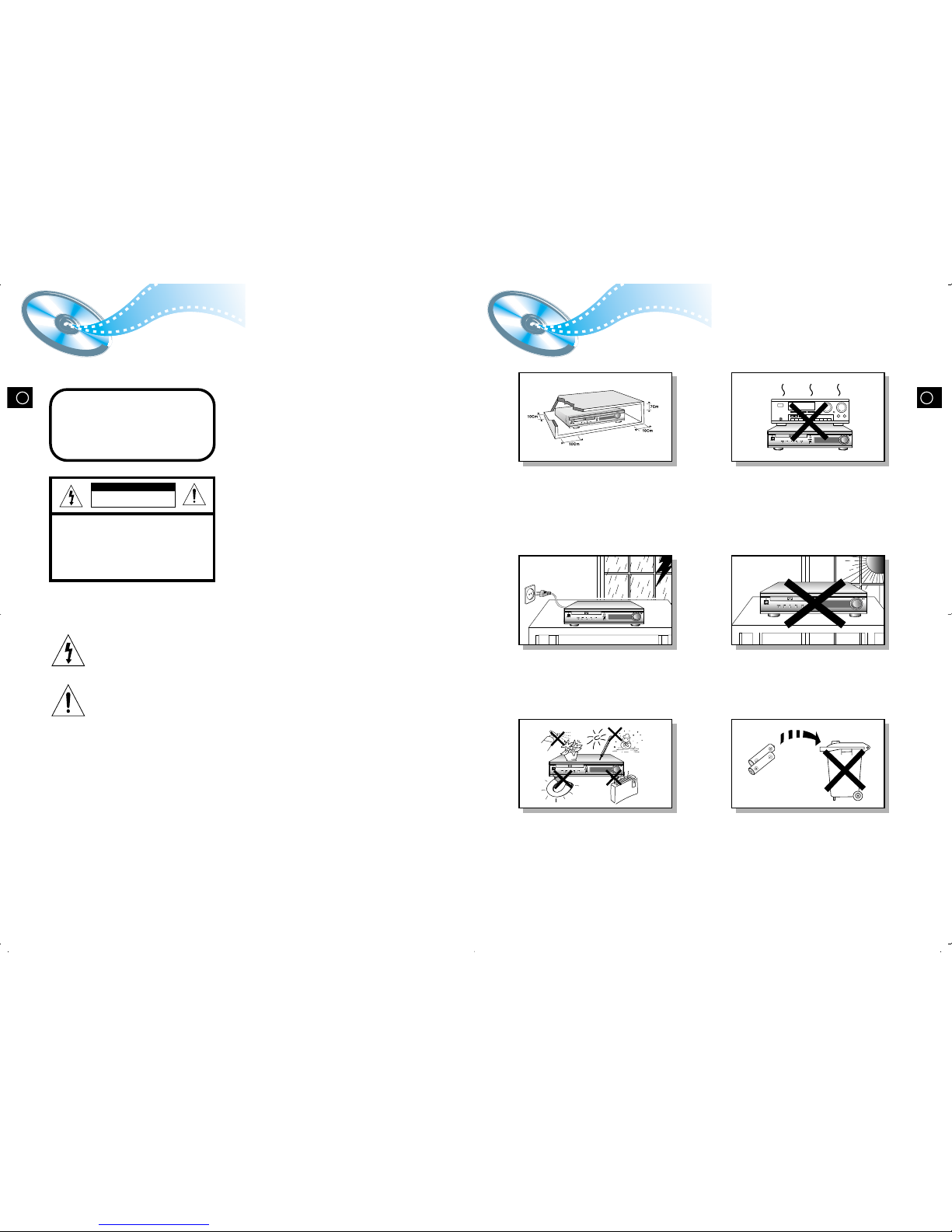
Ensure that the AC power supply in your house complies with the identification sticker located on the back of your player. Install your player
horizontally, on a suitable base (furniture), with enough space around it for ventilation (3~4inches). Make sure the ventilation slots are not
covered. Do not stack anything on top of the player. Do not place the player on amplifiers or other equipment which may become hot.
Before moving the player ensure the disc tray empty. This player is designed for continuous use. Switching off the DVD player to the stand-by
mode does not disconnect the electrical supply. In order to disconnect the player completely from the power supply, remove the main plug
from the wall outlet, especially when left unused for a long period of time.
Protect the player from moisture(i.e. vases) , and excess heat(e.g.fireplace) or
equipment creating strong magnetic or electric fields (i.e.speakers...).
Disconnect the power cable from the AC supply if the player malfunctions.
Your player is not intended for industrial use.
Use of this product is for personal use only.
Condensation may occur if your player or disc has been stored in a cold
atmosphere.
If transporting the player during the winter, wait approximately 2 hours until
the unit has reached room temperature before using.
V
I
D
E
O
V
o
l
u
m
e
F
u
n
c
t
i
o
n
R
R
R
R
During thunderstorms, disconnect AC main plug from the wall
outlet.
Voltage peaks due to lightning could damage the unit.
R
CLASS 1 LASER PRODUCT
This Compact Disc player is classified as a CLASS 1
LASER product.
Use of controls, adjustments or performance of
procedures other than those specified herein may result
in hazardous radiation exposure.
CAUTION-INVISIBLE LASER RADIATION WHEN OPEN
AND INTERLOCKS DEFEATED, AVOID
EXPOSURE TO BEAM.
This symbol indicates that dangerous voltage which can cause electric shock is present inside
this unit.
This symbol alerts you to important operating and maintenance instructions accompanying
the unit.
WARNING: To reduce the risk of fire or electric shock, do not expose this appliance to rain or moisture.
CAUTION: TO PREVENT ELECTRIC SHOCK, MATCH WIDE BLADE OF PLUG TO WIDE SLOT, FULLY
INSERT.
CLASS 1 LASER PRODUCT
KLASSE 1 LASER PRODUKT
LUOKAN 1 LASER LAITE
KLASS 1 LASER APPARAT
PRODUCTO LASER CLASE 1
RISK OF ELECTRIC SHOCK.
DO NOT OPEN
CAUTION:
TO REDUCE THE RISK OF ELECTRIC
SHOCK, DO NOT REMOVE REAR COVER.
NO USER SERVICEABLE PARTS INSIDE.
REFER SERVICING TO QUALIFIED
SERVICE PERSONNEL.
CAUTION
Do not expose the unit to direct sun radiation or other heat
sources.
This could lead to overheating and malfunction of the unit.
The battery used with this product contain chemicals that are
harmful to the environment.
Do not dispose of batteries in the general household trash.
2
GB
4
GB
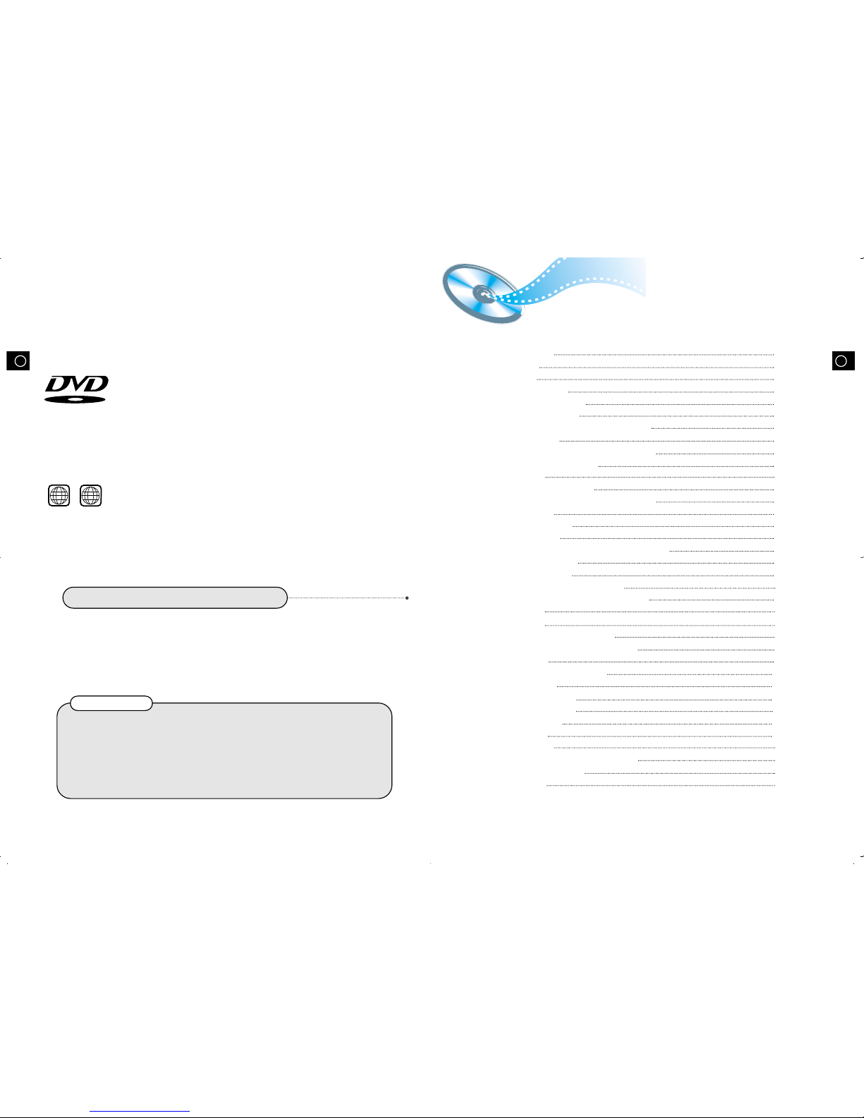
DVD (Digital Versatile Disc) offers fantastic audio and video, thanks to Dolby
Digital surround sound and MPEG-2 video compression technology. Now you can
enjoy these realistic effects in the home, as if you were in a movie theater or concert
hall.
V I D E O
DVD players and the discs are coded by region. These regional codes must match in
order for the disc to play. If the codes do not match, the disc will not play.
The Region Number for this player is given on the rear panel of the player.
(Your DVD player will only play DVDs that are labeled with identical region codes.)
1 6
~
3
Contents
Copy Protection
•
Many DVD discs are encoded with copy protection. Because of this, you should only connect your
DVD player directly to your TV, not to a VCR. Connecting to a VCR results in a distorted picture
from copy-protected DVD discs.
•
This product incorporates copyright protection technology that is protected by methods claims of certain
U.S. patents and other intellectual property rights owned by Macrovision Corporation and other rights
owners. Use of this copyright protection technology must be authorized by Macrovision Corporation, and
is intended for home and other limited viewing uses only unless otherwise authorized by Macrovision
Corporation. Reverse engineering or disassembly is prohibited.
Safety Warnings
Precautions
Description
Remote Control Unit
Connecting the Speakers
Connecting Video to TV
Connecting the FM and AM/MW Antennas
AUX Connections
Connecting your System to the Power Supply
Before Using the DVD Player
DVD Playback
Forward/Reverse Searching
Slow Playback/Checking the Remaining Time
Repeat Playback
Using Disc Menu/Title
Program Playback
Selecting the Audio Language/Subtitle Language
Various DVD Functions
•
To enlarge an image
•
Selecting the desired Screen Angle
•
To move directly to a title, chapter, or time
MP3 Playback
System Setup
Setting up the Language Features
Activating Dynamic Range Compression
Speaker Setup
Creating Realistic Sound Fields
DSP/EQ Function
Power Sound Function
Listening to the Radio
Presetting stations
Sleep Function
Troubleshooting
Cautions on Handling and Storing Discs
Disc Type and Protection
Specifications
1
2
5
7
9
10
11
12
13
14
15
17
18
19
20
21
23
24
24
24
24
25
27
29
30
31
35
36
36
37
38
39
40
42
43
44
•
LD, CDG, CD-I, CD-ROM and DVD-ROM cannot be played on this player.
If such discs are played, a "WRONG DISC FORMAT" message appears on the TV screen.
•
DVD discs purchased abroad may not play on this player.
If such discs are played, a "WRONG REGION CODE" message appears on the TV screen.
Do not use the following types of disc!
GBGB
R
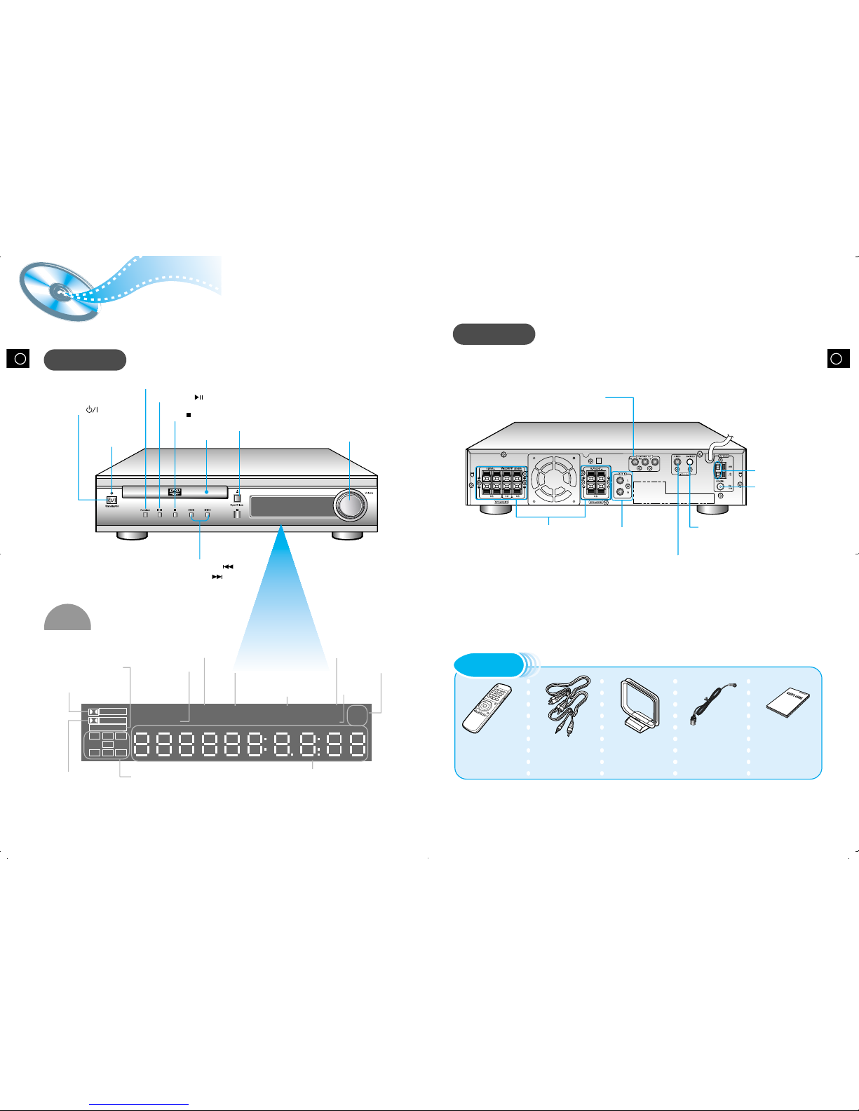
Function button
Standby indicator
Disc Tray
Open/Close button
Volume control
Power ( ) button
Play/Pause ( ) button
Stop ( ) button
65
Description
Front Panel
Remote Control Video/Audio Cable User's Manual FM Antenna AM Antenna
Accessories
Display
Rear Panel
Tuning Down & Skip ( ) button
Tuning up & Skip ( ) button
TITLE indicator
SURROUND
PRO LOGIC
LINEAR PCM
TITLE
TUNED
PROGRAM PBC
MHZ
KHZ
DSP
ST
LCR
LS
LFE
SRS
D I G I T A L
STEREO indicator
DSP
indicator
RADIO
FREQUENCY
indicator
PROGRAM
indicator
System Status Display
LINEAR PCM indicator
TUNER indicator
PBC
indicator
DOLBY DIGITAL
indicator
PRO LOGIC indicator
VIDEO
ANTENN
A
S-VIDEO
5.1 Channel Speaker
Output Terminals
External Audio
Component Input
Connector
S-Video Output Connector
If the TV is equipped with an S-Video
input connector (S-VIDEO IN), connect it
to the player's S-Video output jack.
AM Antenna
Connector
FM Antenna
Connector
COMPONENT VIDEO OUTPUT jacks
Connect a TV with component video
input jacks to these jacks.
Video Output Connector
Connect the TV's video input
jacks (VIDEO IN) to the VIDEO
OUT connector.
SPEAKER indicator
GBGB
7 8
DVD
Band
A<->B
AUX Open/Clse
Display Return
DVD/CD/TUNER
Volume
DSP/EQ Power Sound Mute Sleep
Go To Zoom
Title Menu
StepRemain
SubtitleAudio
MO/ST
RepeatRepeat
Enter
+
Tuning
Down Up
TUNER
123
456
789
Sound Edit
SPK Mode
Pro Logic
Slow
Angle
Subwoofer
Test ToneSetup
Program
D.R.C
Center Speaker
Rear Speaker
Clear
0
+— +—
+—
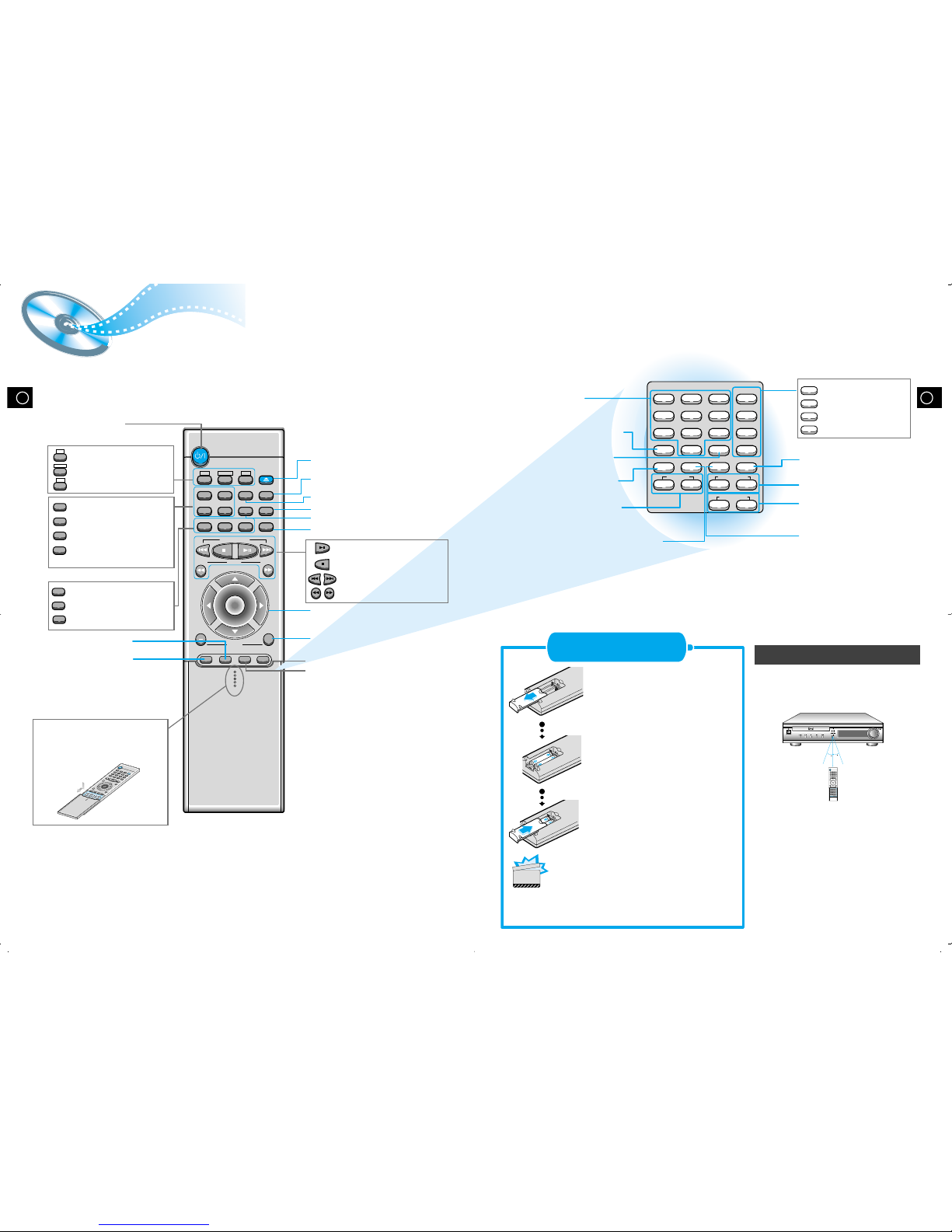
Remote Control Unit
R
3
0
3
0
7~10m
Remove the battery cover on
the back of the remote by
pressing down and sliding the
cover in the direction of the
arrow.
Insert Remote Batteries
Range of Operation of the Remote Control
1
Insert two 1.5V AAA batteries,
paying attention to the correct
polarities (+ and –).
2
Replace the battery cover.
3
The remote control can be used up to
approximately 23 feet/7 meters in a straight line.
It can also be operated at a horizontal angle of
up to 30° from the remote control sensor.
DVD POWER button
DSP/EQ button
Power Sound button
Slow button
Setup button
Angle button
Subwoofer Speaker
button
D.R.C button
Title
Menu
Subtitle
Audio
MO/ST
Display
Return
Go To
DVD button
TUNER button
AUX button
Title button
Menu button
Subtitle button
Audio
MO/ST(mono/stereo) button
Display button
Return button
Go To button
DVD
TUNER
Band
AUX
Mute button
Volume Control buttons
Speaker output volume control
Play/Pause button
Stop button
Tuning Preset/CD Skip button
Tuning Up/Down/CD Search button
Sleep button
Clear button
Center Speaker button
Rear Speaker button
Program button
Direction/Enter button
Open/Close button
Step button
Remain button
Repeat (A<->B) button
Repeat button
Zoom button
Sound Edit
SPK Mode
Pro Logic
Test Tone
Sound Edit button
SPK Mode button
Pro Logic button
Test Tone button
To open the romote control
cover, push the top of the
cover, then slide downward.
Follow these precautions to avoid leaking or cracking cells:
•
Place batteries in the remote control so they match the
polarity:(+) to (+)and (–)to (–).
•
Use the correct type of batteries.Batteries that look similar
may differ in voltage.
•
Always replace both batteries at the same time.
•
Do not expose batteries to heat or flame.
CAUTION
Selection button
GBGB
9
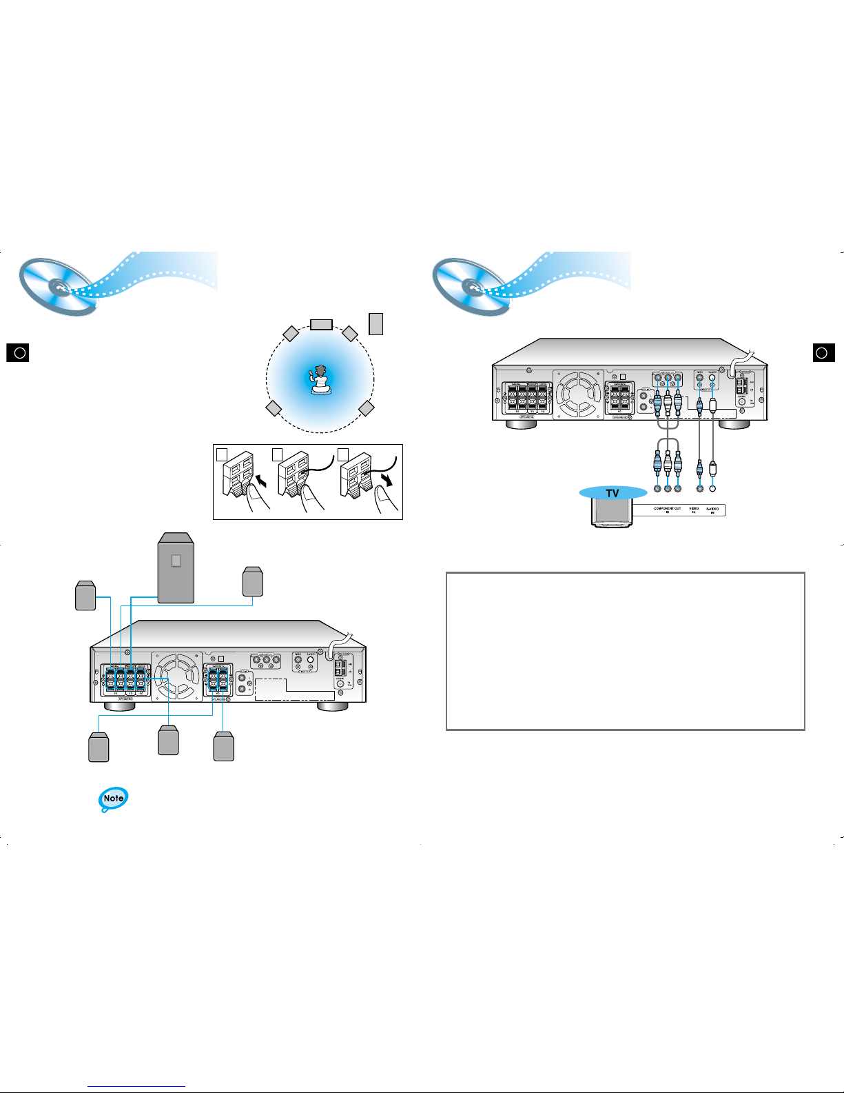
Connecting the Speakers Connecting
Video to TV
• Connect the satellite speakers, center speaker, and
subwoofer to the terminals on the rear panel using speaker
cords supplied.
• Insert the end of the speaker cord into the terminal.
Match the polarity (colors): Red (+) to red (+) and black (–) to
black (–).
Subwoofer
Left front
speaker
Left rear
speaker
Right rear
speaker
Right front
speaker
Center
speaker
Press and hold the terminal tab.
1
Insert the speaker cord.
2
Release your finger.
3
1 2 3
•
for in-depth information about adjusting the delay time,
see “Speaker Settings” on page 32.
10
Composite Video (Good Quality)
Connect the supplied video cable from the VIDEO OUT jack on the back panel of the
system to the VIDEO IN jack on your television.
S-Video (Better Quality)
If you television is equipped with an S-Video input, connect an S-Video cable (not supplied)
from the S-VIDEO OUT jack on the back panel of the system to the S-VIDEO IN jack on
your television.
Component Video (Best Quality)
If your television is equipped with Component Video inputs, connect a component video
cable (not supplied) from the Pr, Pb and Y jacks on the back panel of the system to the
corresponding jacks on your television.
VIDEO
ANTENN
A
S-VIDEO
VIDEO
ANTENN
A
S-VIDEO
Right rear speaker
Right front speaker
Left front speaker
Left rear speaker
Center speaker
Subwoofer
GBGB
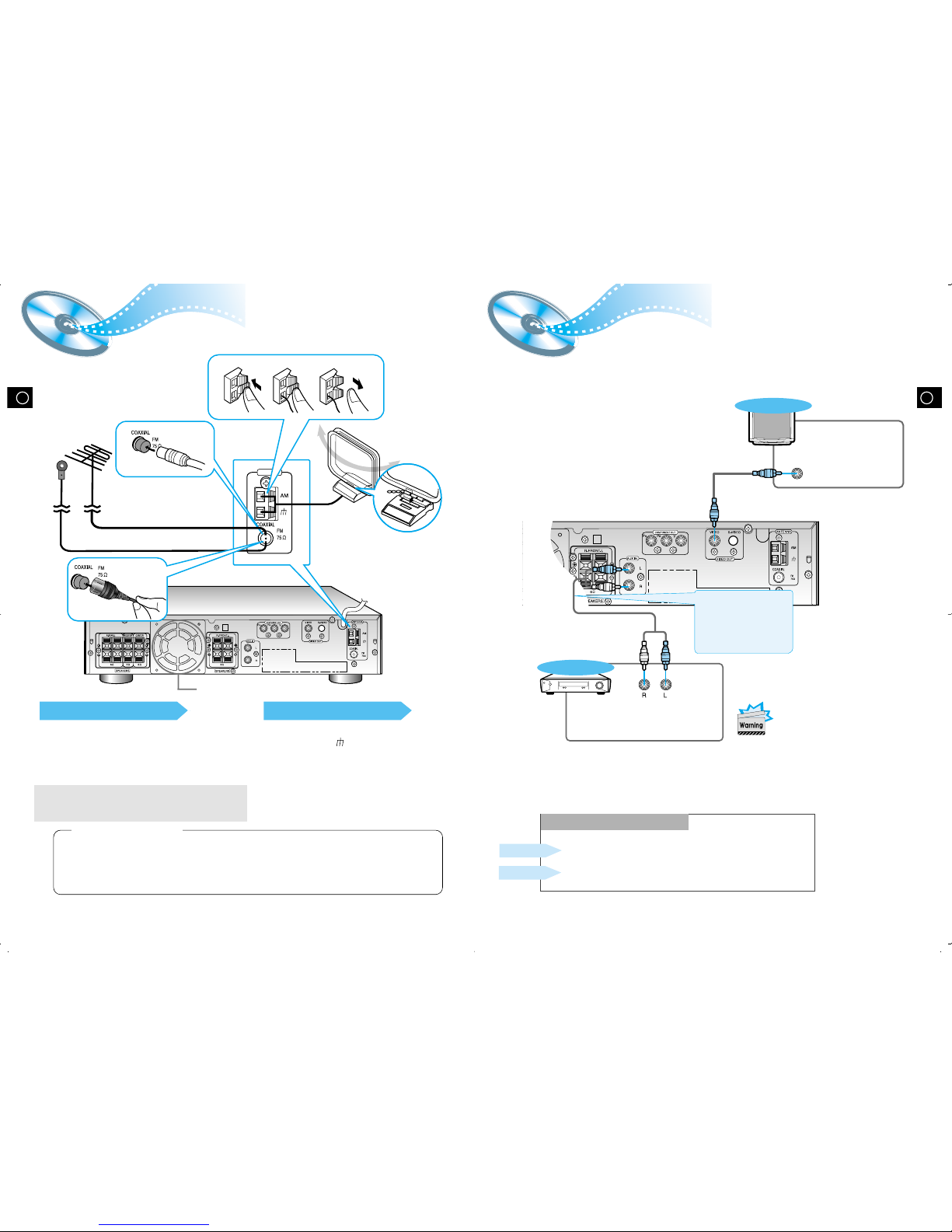
FM antenna connection
1. Connect the FM antenna supplied to the FM 75Ω
COAXIAL terminal.
2. Slowly move the antenna wire around until you
find a location where reception is good, then
fasten it to a wall or other rigid surface.
•
If reception is poor, connect an outdoor antenna.
Before attaching a 75Ω coaxial cable (with a standard
type connector), disconnect the supplied FM antenna.
AM/MW antenna connection
1. Connect the AM loop antenna supplied
to the AM and terminals.
2. If reception is poor, connect an outdoor
single vinyl-covered wire to the AM
terminal. (Keep the AM loop antenna
connected).
12
Connecting the FM and AM
(
MW/LW
)
Antennas
11
A cooling fan is mounted on the rear panel of the center unit to
prevent abnormal temperature inside the center unit, thus assuring
normal operation. The cooling fan automatically starts rotating to
supply external cool air to the inside of the center unit when the
internal temperature exceeds the specified limit.
For safety, observe the following carefully.
• Make sure there is good ventilation around the center unit. Poor
ventilation could overheat and damage the canter unit.
• DO NOT block the cooling fan and the ventilation openings or
holes. (If they are blocked by a newspaper or cloth, etc., the heat
may not be able to escape.)
(About the cooling fan)
AUX Connections
Snap the tabs on the loop into the
slots of the base to assemble the
AM loop antenna.
Cooling fan (See “About Cooling Fan” below.)
VIDEO
ANTENN
A
S-VIDEO
ANTENNA
123
If FM reception is poor,
connect outdoor FM antenna
(not supplied).
FM Antenna (supplied)
AM Loop Antenna
(supplied)
If AM reception is
poor, connect an
outdoor AM
antenna(not
supplied).
VIDEO
ANTENN
A
S-VIDEO
VIDEO IN
TV
External Analog
Components
Audio Cable (Red/White)
To view pictures from the
external input (AUX),
first connect the VIDEO
IN jack (VIDEO) and then
connect the VIDEO OUT
jack.
Connect to external equipment with
analog outputs.
Example: Video, TV, etc.
•
Always connect the video and
audio connection cables to the
equivalent colored jack.
Press the AUX button and select AUX IN.
Making Analog Input Selection
Press the Function button and select AUX IN.
Remote Control
Main Unit
If the external analog
component has only one
output jack, you may
connect either L or R.
GBGB
•
The “WAIT” message that appears on the display for about seven to eight seconds when
turning on the power or selecting a DVD function indicates a stabilization period for
optimizing the condition of your DVD player. While the message is being displayed, other
buttons remain inactive.
•
When the power is not turned on, press down the Stop ( ) button on the main unit for
over 5 seconds.
The product will be initialized to its optimum state.
•
Certain operational features such as the Speaker mode, Test tone, Volume, etc.
will not be displayed on the TV screen.
Before Using the DVD Player
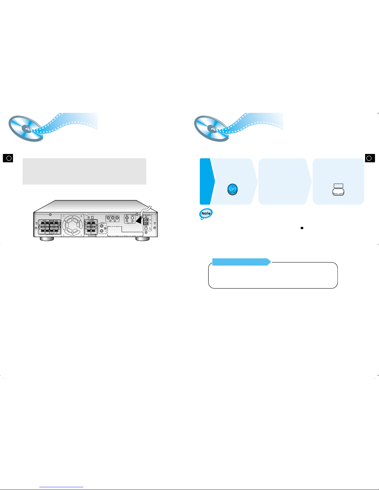
Connecting your System to the Power Supply
14
Your DVD player is capable of playing DVD, VCD, and CD discs.
User instructions may vary depending on the type of disc. Read the instructions
carefully before use.
DVD
Preparations
before
use
Turn on the power
to your DVD player
and TV.
1
Select a video mode by
pressing the TV/VIDEO
button.
2
Press the DVD button
to select the DVD input
function.
3
TV Broadcast System
• This device is designed to work with the NTSC video format.
• For normal playback, the video format a DVD disc is recorded in must
coincide with your TV's video format.
13
The AC plug must be plugged into an appropriate socket.
Before plugging your system into an AC outlet, you must check the voltage.
1. Plug the AC Cord on the rear of the system into an appropriate outlet.
2. Press the On/Standby button to switch your DVD Player system on.
VIDEO
ANTENN
A
S-VIDEO
SPEAKERS
 Loading...