

DIGITAL HOME
THEATER SYSTEM
HT-DM550
V I D E O
COMPACT
DIGITAL AUDIO
COMPACT
DIGITAL VIDEO
Instruction Manual
AH68-01142R
SAMSUNG ELECTRONICS CANADA, INC.
Bureau-chef
7037 Financial Drive, Mississauga, Ontario, Canada L5N 6R3
TEL: 1-905-542-3535
www.samsung.ca
Centre de service
7037 Financial Drive, Mississauga, Ontario, Canada L5N 6R3
1-800-SAMSUNG (1-800-726-7864)
PrecautionsSafety W arnings
1
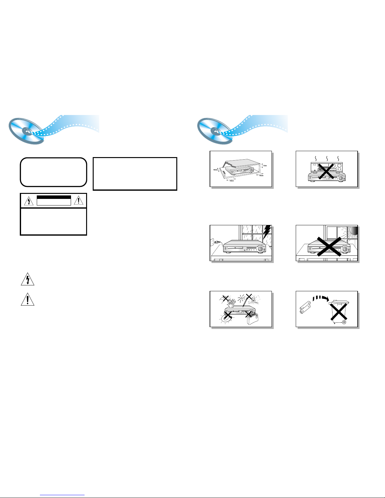
Ensure that the AC power supply in your house complies with the identification sticker located on the back of your player. Install your player
horizontally, on a suitable base (furniture), with enough space around it for ventilation (3~4inches). Make sure the ventilation slots are not
covered. Do not stack anything on top of the player. Do not place the player on amplifiers or other equipment which may become hot.
Before moving the player, ensure the disc tray is empty. This player is designed for continuous use. Switching off the DVD player to the stand-by
mode does not disconnect the electrical supply. In order to disconnect the player completely from the power supply, remove the main plug from
the wall outlet, especially when left unused for a long period of time.
Protect the player from moisture(i.e. vases) , and excess heat(e.g.fireplace) or
equipment creating strong magnetic or electric fields (i.e.speakers...).
Disconnect the power cable from the AC supply if the player malfunctions.
Your player is not intended for industrial use.
Use of this product is for personal use only.
Condensation may occur if your player or disc have been stored in cold
temperatures.
If transporting the player during the winter, wait approximately 2 hours until
the unit has reached room temperature before using.
Phones
During thunderstorms, disconnect AC main plug from the wall
outlet.
Voltage peaks due to lightning could damage the unit.
CLASS 1 LASER PRODUCT
This Compact Disc player is classified as a CLASS 1
LASER product.
Use of controls, adjustments or performance of
procedures other than those specified herein may result
in hazardous radiation exposure.
CAUTION-INVISIBLE LASER RADIATION WHEN OPEN
AND INTERLOCKS DEFEATED, AVOID
EXPOSURE TO BEAM.
This symbol indicates that dangerous voltage which can cause electric shock is present inside
this unit.
This symbol alerts you to important operating and maintenance instructions accompanying
the unit.
WARNING: To reduce the risk of fire or electric shock, do not expose this appliance to rain or moisture.
CAUTION: TO PREVENT ELECTRIC SHOCK, MATCH WIDE BLADE OF PLUG TO WIDE SLOT, FULLY
INSERT.
CLASS 1 LASER PRODUCT
KLASSE 1 LASER PRODUKT
LUOKAN 1 LASER LAITE
KLASS 1 LASER APPARAT
PRODUCTO LASER CLASE 1
RISK OF ELECTRIC SHOCK.
DO NOT OPEN
CAUTION:
TO REDUCE THE RISK OF ELECTRIC
SHOCK, DO NOT REMOVE REAR COVER.
NO USER SERVICEABLE PARTS INSIDE.
REFER SERVICING TO QUALIFIED
SERVICE PERSONNEL.
CAUTION
Do not expose the unit to direct sun radiation or other heat
sources.
This could lead to overheating and malfunction of the unit.
The battery used with this product contain chemicals that are
harmful to the environment.
Do not dispose of batteries in the general household trash.
2
Note to CATV system installer :
This reminder is provided to call the CATV system
installer’s attention to Section 820~40 of the NEC
which provides guidelines for proper grounding and,
in particular, specifies that the cable ground shall be
connected to the grounding system of the building,
as close to the point of cable entry as practical
4
DVD (Digital Versatile Disc) offers fantastic audio and video, thanks to Dolby
Digital surround sound and MPEG-2 video compression technology. Now you can
enjoy these realistic effects in the home, as if you were in a movie theater or concert
hall.
V I D E O
DVD players and the discs are coded by region. These regional codes must match in
order for the disc to play. If the codes do not match, the disc will not play.
The Region Number for this player is given on the rear panel of the player.
(Your DVD player will only play DVDs that are labeled with identical region codes.)
1 6
~
3
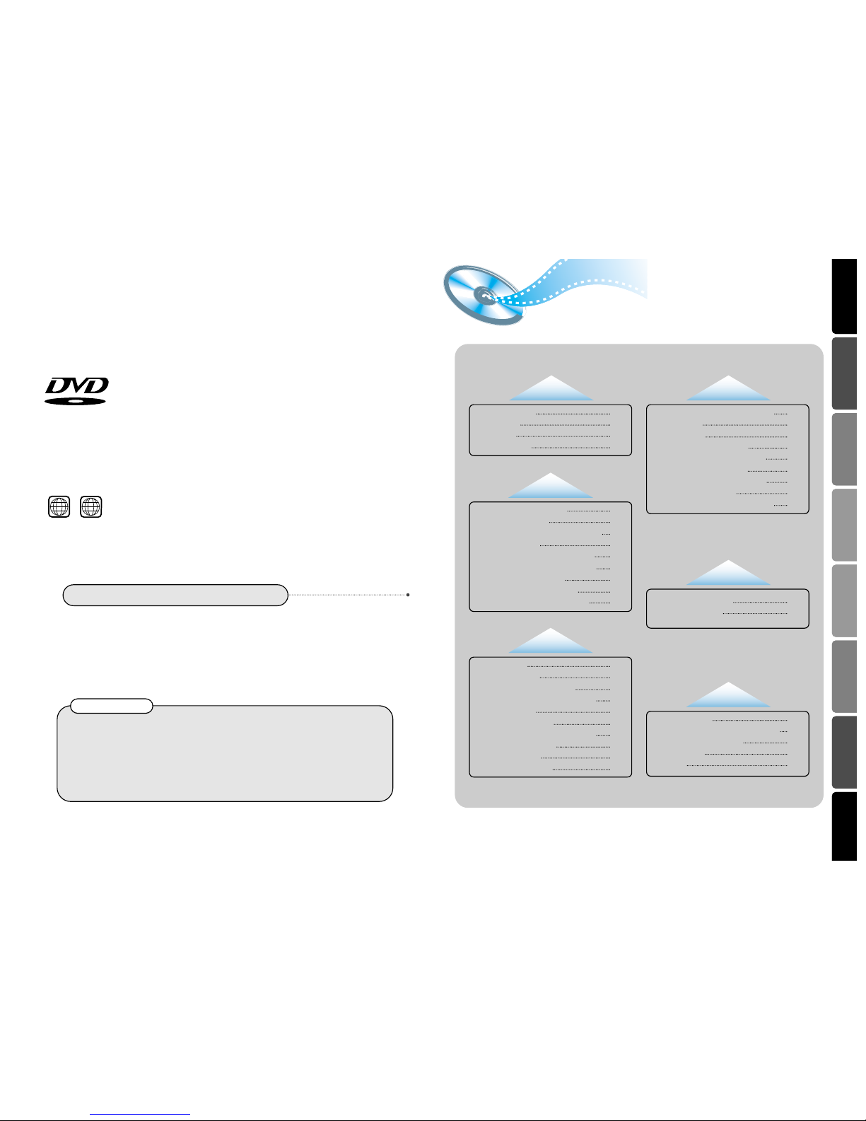
Contents
Copy Protection
•
Many DVD discs are encoded with copy protection. Because of this, you should only connect your
DVD player directly to your TV, not to a VCR. Connecting to a VCR results in a distorted picture
from copy-protected DVD discs.
•
This product incorporates copyright protection technology that is protected by methods claims of certain
U.S. patents and other intellectual property rights owned by Macrovision Corporation and other rights
owners. Use of this copyright protection technology must be authorized by Macrovision Corporation, and
is intended for home and other limited viewing uses only unless otherwise authorized by Macrovision
Corporation. Reverse engineering or disassembly is prohibited.
•
LD, CD-G, CD-I, CD-ROM and DVD-ROM cannot be played on this player.
If such discs are played, a "WRONG DISC FORMAT" message appears on the TV screen.
•
DVD discs purchased abroad may not play on this player.
If such discs are played, a "WRONG REGION CODE" message appears on the TV screen.
Do not use the following types of disc!
Safety Warnings
Precautions
Description
Remote Control
CHAPTER 1.
PREPARATION
1
2
5
7
Setting up the Language Features
System Setup
Speaker Setup
To set up Speaker Balance
Creating Realistic Sound Fields
Dolby Pro Logic II decoder
DSP
(Digital Signal Processor) Modes
To increase Effect level
Adjusting DSP Sound Parameters
CHAPTER 4.
SETUP
30
31
33
35
36
37
39
40
40
Troubleshooting
Cautions on Handling and Storing Discs
Disc Type and Protection
Specifications
Warranty
CHAPTER 6.
MISCELLANENOUS
43
45
46
47
48
Listening to the Radio
Presetting stations
CHAPTER 5.
RADIO OPERATION
41
42
Connecting the Speakers
Connect Video to TV
Connecting the FM and AM(MW/LW) Antennas
AUX Connections
Controlling a TV with the Remote
Connecting your System to the Power Supply
Listening on headphones
Before Using the DVD Player
P.SCAN
(Progressive Scan) Function
9
10
11
12
13
14
14
15
16
CHAPTER 2.
CONNECTIONS
DVD Playback
MP3-CD Playback
Forward/Reverse Searching
Slow Playback/Checking the Remaining Time
Repeat Playback
Using Disc Menu/Title
Selecting the Audio Language/Subtitle Language
Zoom/Angle Functions
Program Playback
Sleep/D.R.C Function
17
19
21
22
23
24
25
26
27
29
CHAPTER 3.
OPERATION
65
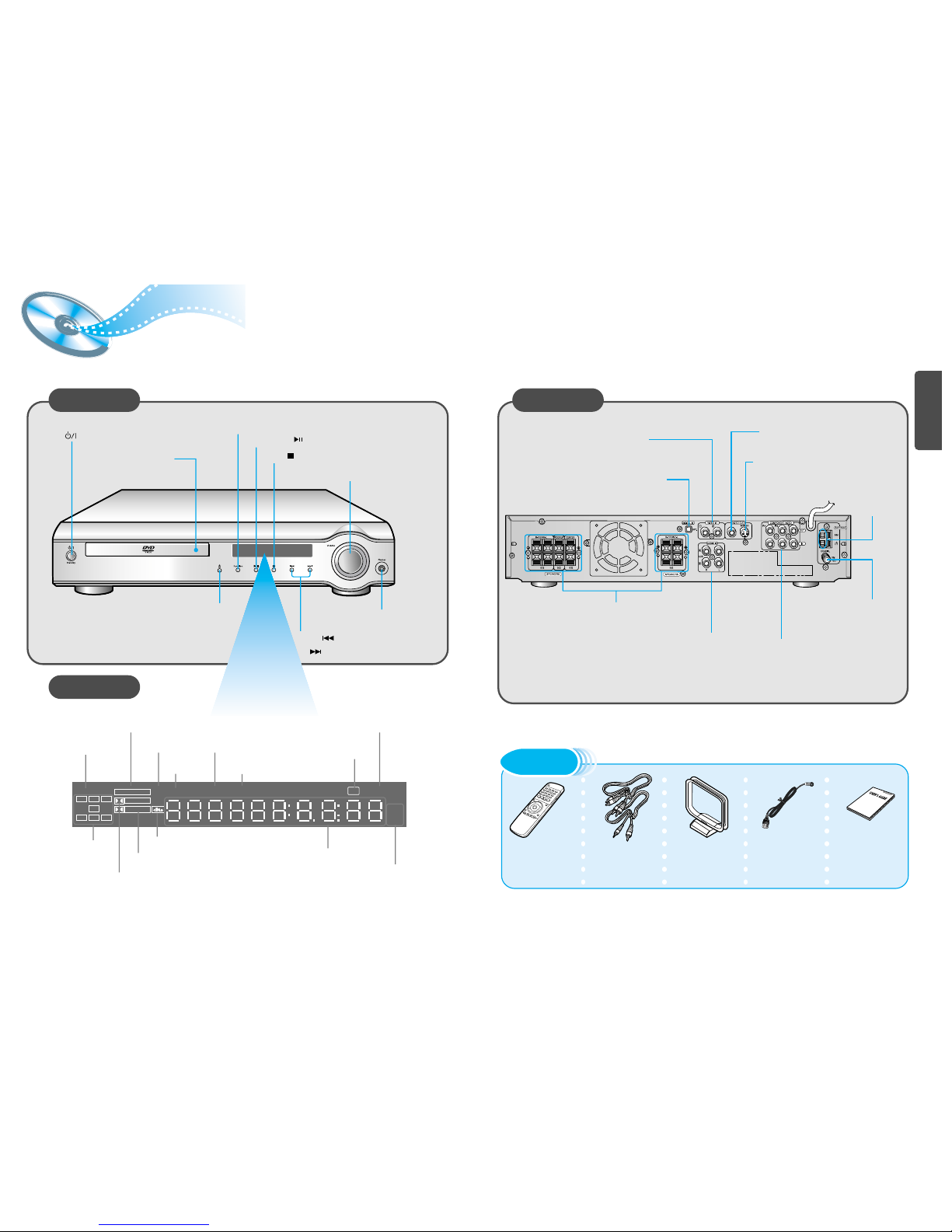
Description
Front Panel
Display
Remote Control Audio/Video Cable User's Manual FM Antenna AM Antenna
Accessories
Volume control
Play/Pause ( ) button
Stop ( ) button
Power ( ) button
Headphone Jack
Open/Close button
Disc Tray
Function button
Rear Panel
5.1 Channel Speaker
Output Terminals
FM Antenna
Connector
Tuning Down & Skip ( ) buttons
Tuning Up & Skip ( ) buttons
External Digital Component Input
Connector
Use this to connect external equipment
capable of digital output.
External Video Component
Input Connectors
External Audio Component
Input Connector
Video Output Connector
Connect the TV's video input jacks (VIDEO
IN) to the VIDEO OUT connector.
S-Video Output Connector
If the TV is equipped with an S-Video input
connector (S-VIDEO IN), connect it to the
player's S-Video output jack.
AM Antenna
Connector
COMPONENT VIDEO
OUTPUT/INPUT jacks
Connect a TV with component
video inputs to these jacks.
TITLE
indicator
DTS Disc indicator
PRO LOGIC indicator
PRO LOGIC
LINEAR PCMP . SCAN
DSP TITLE PBC
PRGM
ST TUNED
kH
Z
MH
Z
LCR
LS
LFE
SRS
D I G I T A L
STEREO indicator
DSP PBC
RADIO
FREQUENCY
indicator
PROGRAM
indicator
System Status Display
SPEAKER
indicator
TUNER indicator
LINEAR PCM
indicator
P.SCAN
indicator
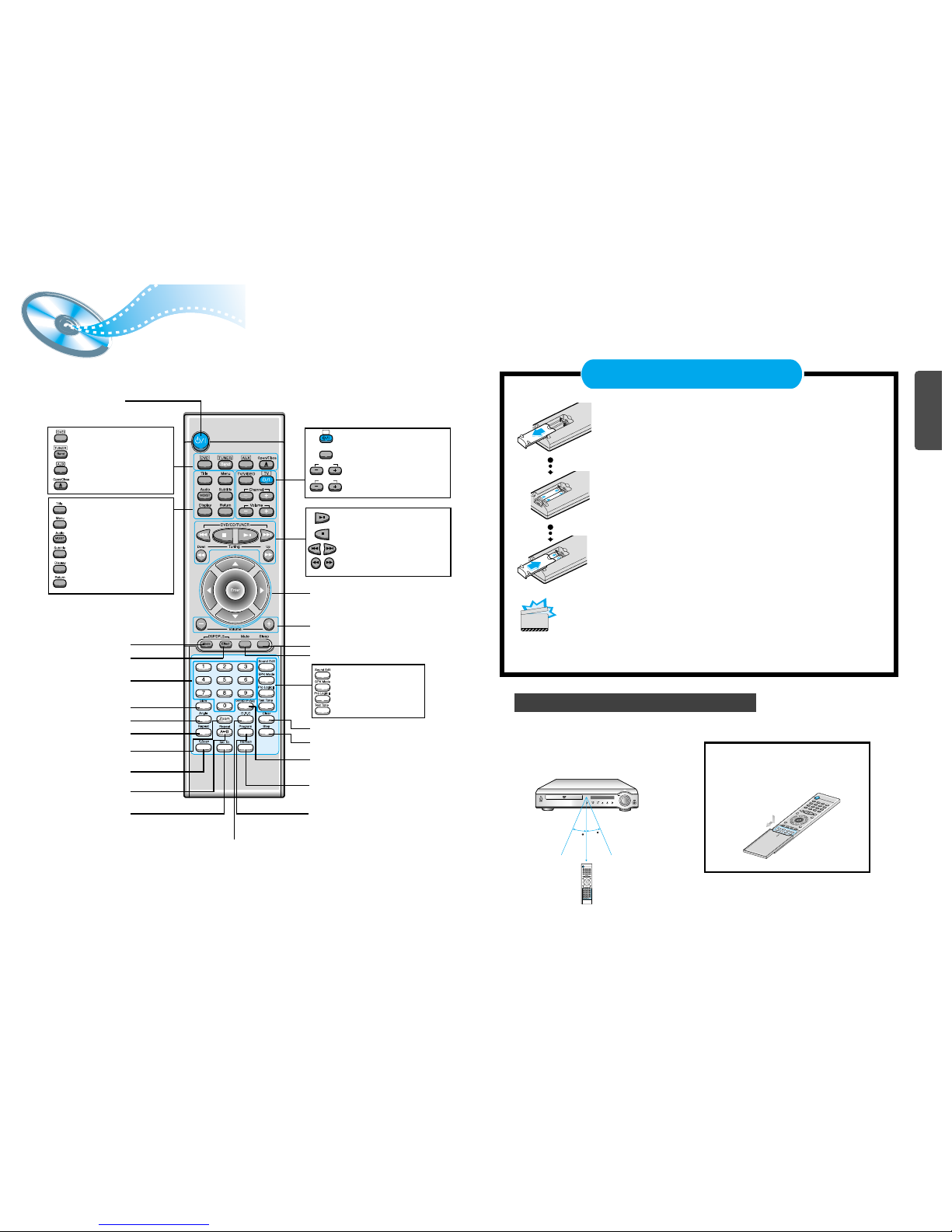
Remote Control Unit
7 8
DVD POWER button
DSP/DPL II Mode button
DSP/DPL II Effect button
Number(0~9) buttons
Slow button
Angle button
Repeat button
Zoom button
P.Scan button
Repeat A↔B button
Go To button
TV Power button
TV/VIDEO button
TV Channel Selection button
TV Volume Control button
Volume
TV
Channel
TV/VIDEO
DVD button
TUNER button
AUX button
Open/Close button
Title button
Menu button
Audio MO/ST(mono/stereo) button
Subtitle button
Display button
Return button
Mute button
Clear button
Volume Control buttons
Speaker output volume control
Play/Pause button
Stop button
Tuning Preset/CD Skip button
Tuning Up/Down/CD Search button
Sleep button
Direction/Enter button
Step button
Setup/P.Scan Adjust button
Remain button
Program button
Sound Edit button
SPK Mode button
Pro Logic II button
Test Tone button
D.R.C button
30
30
7~10m
Remove the battery cover on the back of the remote by pressing
down and sliding the cover in the direction of the arrow.
Insert Remote Batteries
Range of Operation of the Remote Control
1
Insert two 1.5V AAA batteries, paying attention to the correct
polarities (+ and –).
2
Replace the battery cover.
3
The remote control can be used up to
approximately 23 feet/7 meters in a straight line.
It can also be operated at a horizontal angle of
up to 30° from the remote control sensor.
Follow these precautions to avoid leaking or cracking cells:
• Place batteries in the remote control so they match the polarity:(+) to (+)and (–)to (–).
• Use the correct type of batteries.Batteries that look similar may differ in voltage.
• Always replace both batteries at the same time.
• Do not expose batteries to heat or flame.
To open the remote control cover,
push the top of the cover, then slide
downward.
9
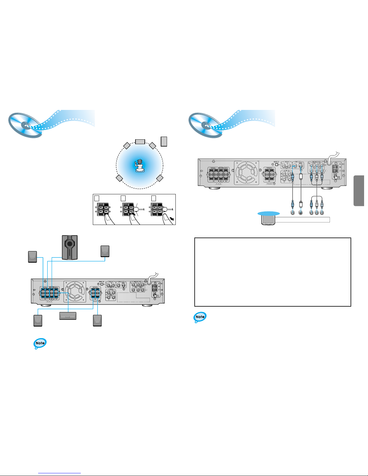
Connecting the Speakers
Connect Video to TV
• Connect the satellite speakers, center speaker, and
subwoofer to the terminals on the rear panel using speaker
cords supplied.
• Connect the red cord to the red (+) terminal and the black
cord to the black (-) terminal.
Subwoofer
Left front
Left rear Right rear
Right front
Center
Press and hold the terminal tab.
1
Insert the speaker cord.
2
Release your finger.
3
1 2 3
•For details on the “Ideal Speaker Placement” see page 34.
10
Right rear speaker
Right front speaker
Left front speaker
Left rear speaker
Subwoofer
Composite Video (Good Quality)
Connect the supplied video cable from the VIDEO OUT jack on the back panel of the
system to the VIDEO IN jack on your television.
S-Video (Better Quality)
If you television is equipped with an S-Video input, connect an S-Video cable (not supplied)
from the S-VIDEO OUT jack on the back panel of the system to the S-VIDEO IN jack on
your television.
Component Video (Best Quality)
If your television is equipped with Component Video inputs, connect a component video
cable (not supplied) from the Pr, Pb and Y jacks on the back panel of the system to the
corresponding jacks on your television.
Composite
Video
Component
Video
S-Video
TV
•
When the Progressive scan mode is selected, the VIDEO and S-VIDEO outputs do not feed
any signals. See page 16 to select Progressive Scan.
*
Depending on your TV, Component Video input connectors may be marked as DVD Video input connectors.
Center speaker
Red
Black
12
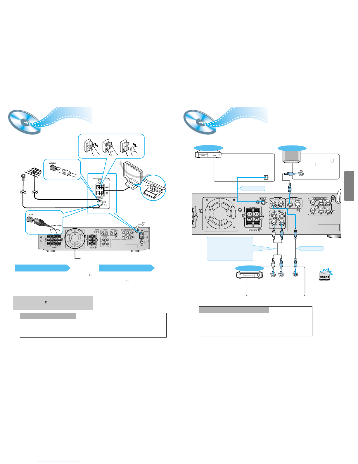
FM antenna connection
1. Connect the FM antenna supplied to the FM 75
COAXIAL terminal as temporary measure.
2. Slowly move the antenna wire around until you
find a location where reception is good, then
fasten it to a wall or other rigid surface.
•
If reception is poor, connect an outdoor antenna.
Before attaching a 75 coaxial cable (with a standard
type connector), disconnect the supplied FM antenna.
AM(MW/LW) antenna connection
1. Connect the AM loop antenna supplied
to the AM and terminals.
2. If reception is poor, connect an outdoor
single vinyl-covered wire to the AM
terminal. (Keep the AM loop antenna
connected).
Connecting the FM and AM
(
MW/LW
)
Antennas
11
A cooling fan is mounted on the rear panel of the center unit to
prevent abnormal temperature inside the center unit, thus assuring
normal operation. The cooling fan automatically starts rotating to
supply external cool air to the inside of the center unit when the
internal temperature exceeds the specified limit.
For safety, observe the following carefully.
• Make sure there is good ventilation around the center unit. Poor
ventilation could overheat and cause damage.
• DO NOT block the cooling fan and the ventilation openings or
holes. (If they are blocked by a newspaper or cloth, etc., the heat
may not be able to escape.)
Snap the tabs on the loop into the
slots of the base to assemble the
AM loop antenna.
Cooling fan (See “About Cooling Fan” below.)
ANTENNA
123
If FM reception is poor,
connect an outdoor FM antenna
(not supplied).
FM Antenna (supplied)
AM Loop Antenna
(supplied)
If AM reception is
poor, connect an
outdoor AM
antenna(not
supplied).
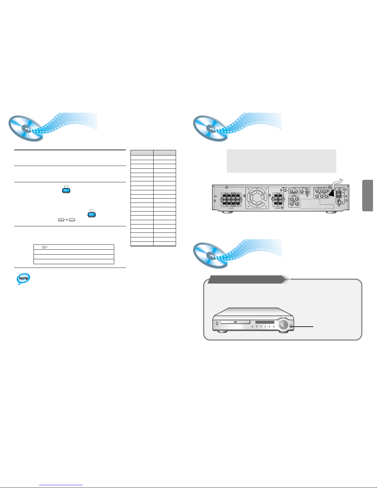
AUX Connections
LR
DIGITAL OUT
VIDEO OUT
VIDEO IN
External Digital
Components
External Analog
Components
Audio Cable (Red/White)
If the external analog
component has only one
output jack, you may connect
either L or R.
For connection to external
equipment with digital output.
Example: CD recorders, MD (Mini Disc) D/A
converters or other components equipped
with digital output jacks
Connect to external equipment with
analog output.
Example: VCR, TV, etc.
•
Always connect the video and
audio connection cables to the
equivalent colored jack.
Press AUX on the remote control to select DIGITAL IN, AUX1, or AUX2.
Press Function on the main unit to select DIGITAL IN, AUX1, or AUX2.
•
Each time the button is pressed the mode switches as follows: FM ➞ AM ➞ DVD ➞
DIGITAL IN ➞ AUX 1 ➞ AUX 2.
To Play External Digital/Analog Equipment
Optical Cable
(not supplied)
Video Cable
To view pictures from
external input (AUX 1 ,
AUX 2 ), first connect the
VIDEO IN jack and then
connect the VIDEO OUT
jack.
TV
(About the cooling fan)
13 14
The AC Cord must be plugged into an appropriate socket.
Before plugging your system into an AC outlet, you must check the voltage.
1. Plug the AC Cord on the rear of the system into an appropriate outlet.
2. Press the On/Standby button to switch your DVD Player system on.
Connecting your System to the Power Supply
Controlling a TV with the Remote
You can operate your TV by adjusting the DVD remote signal .
1
Turn on the TV.
2
Point the DVD’s remote at the TV.
•
Manufacturers’ codes are subject to change without notice.
If they are changed, this remote control cannot operate the equipment.
4
If the TV turns off, setup is complete.
•
Now, you can perform the following operations on the TV.
3
While holding the button down, enter the
code for your brand.
TV
example : For SAMSUNG 1TVs
While holding down the button,
enter .
TV
Manufacturer
01~06,32
12
12
09,17,21
11,13,14,24
32
02,30
02,16
29
23
13,14,24
08,23~27
02,20,22
13,14,22~24
12,16
02
10,31
15,16
14,24,28
13,14,24,33,34
07,16~19,21
Samsung
Akai
FIisher
Grundig
Hitachi
JVC
LG
Mitsubishi
Mival
Nokia
Nordmende
Panasonic
Philips
Saba
Sanyo
Schneider
Sharp
Sony
Telefunken
Thomson
Toshiba
CODES
•
If there is more than one code listed in the table,
enter one at a time to determine which code works.
TV : Turn on or off the TV.
VOLUME +/– : Adjust the volume.
TV/VIDEO : Set the input mode (either TV or VIDEO)
CHANNEL +/– : Change the channels.
Listening on headphones
Listening on headphones
Use headphones (not supplied) for private listening pleasure.
Connect the headphones to the HEADPHONE jack of the front panel.
• No sound is produced from the speakers.
• To prevent hearing damage, do not raise the volume level excessively when using headphones.
HEADPHONE jack
 Loading...