

Page 1
Flow Regulators
with Electric Actuator
Type 2488/5824 and
Type 2488/5825
Mounting and
Operating Instructions
EB 3135-1 EN
Edition June 2008
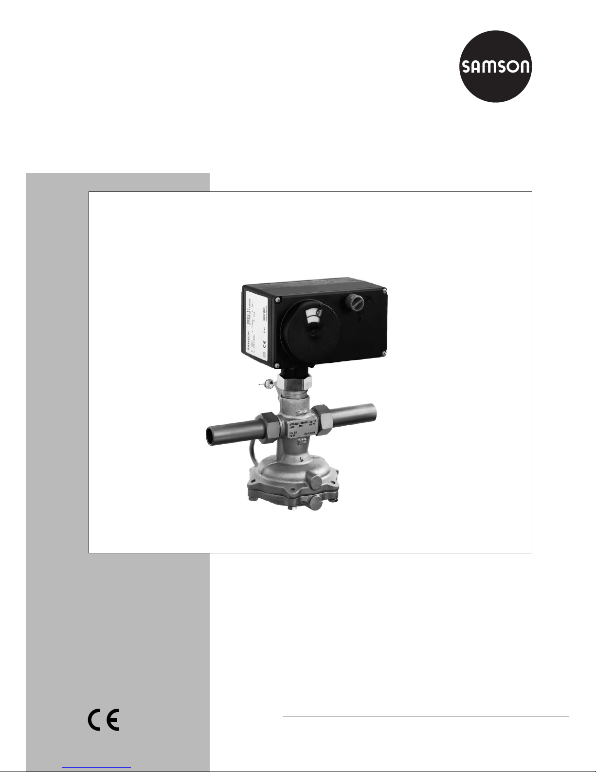
Fig. 1 · Type 2488/5824 Flow Regulator with Electric Actuator
Page 2

Contents Page
1 Design and principle of operation . . . . . . . . . . . . . . . . . . . 4
2 Installation . . . . . . . . . . . . . . . . . . . . . . . . . . . . . . . 4
2.1 Mounting position . . . . . . . . . . . . . . . . . . . . . . . . . . . 4
2.2 Strainer . . . . . . . . . . . . . . . . . . . . . . . . . . . . . . . . 4
2.3 Additional installation instructions . . . . . . . . . . . . . . . . . . . . 6
3 Operation . . . . . . . . . . . . . . . . . . . . . . . . . . . . . . . 6
3.1 Start-up . . . . . . . . . . . . . . . . . . . . . . . . . . . . . . . . 6
3.2 Set point adjustment . . . . . . . . . . . . . . . . . . . . . . . . . . 6
3.2.1 Adjustment without actuator. . . . . . . . . . . . . . . . . . . . . . . 6
3.2.2 Adjustment with Type 5824 Actuator . . . . . . . . . . . . . . . . . . 7
3.2.3 Adjustment with Type 5825 Actuator . . . . . . . . . . . . . . . . . . 7
4 Maintenance–Replacing parts . . . . . . . . . . . . . . . . . . . . . 8
4.1 Replacing the orifice . . . . . . . . . . . . . . . . . . . . . . . . . . 8
4.2 Cleaning or replacing the plug. . . . . . . . . . . . . . . . . . . . . . 9
4.3 Replacing the diaphragm . . . . . . . . . . . . . . . . . . . . . . . . 9
5 Nameplate. . . . . . . . . . . . . . . . . . . . . . . . . . . . . . . 9
6 Troubleshooting. . . . . . . . . . . . . . . . . . . . . . . . . . . . 10
7 Customer inquiries . . . . . . . . . . . . . . . . . . . . . . . . . . 10
8 Dimensions and weights . . . . . . . . . . . . . . . . . . . . . . . 11
2 EB 3135-1 EN
Contents
Note!
Non-electric actuators and control valve versions do not have their own potential ignition
source according to the ignition risk assessment stipulated in EN 13463-1: 2001, section
5.2, even in the rare incident of an operating fault. Therefore, they do not fall within the
scope of Directive 94/9/EC.
For connection to the equipotential bonding system, observe the requirements specified in
EN 60079-14: 1977 (VDE 0165 Part 1), section 6.3.
Page 3
General safety instructions
EB 3135-1 EN 3
General safety instructions
4
The flow regulator must be installed, started up, and serviced only by skilled
or semi-skilled staff in accordance with good engineering practice so that
employees and third persons are not exposed to danger.
All safety instructions and warnings given in these mounting and operating
instructions, particularly those concerning installation, start-up, and
maintenance, must be strictly observed.
4
The regulator complies with the requirements of the European Pressure
Equipment Directive 97/23/EC. The declaration of conformity issued for a
valve bearing the CE marking includes information on the applied
conformity assessment procedure and will be provided on request.
4
To ensure appropriate use, only use the regulator in applications where the
operating pressure and temperatures do not exceed the operating values
specified in the order.
Note that the manufacturer does not assume any responsibility for damage
caused by external forces or any other external factors.
Take appropriate safety precautions to prevent hazards that may be caused
in the regulator by the process medium, operating pressure, or moving parts.
4
Make sure the regulator is shipped and stored properly.
4
The electric actuator has been designed for use in electrical power
installations. Strictly observe the relevant safety regulations for wiring and
maintenance work. Only use disconnect devices that are protected against
accidental or inadvertent reconnection. Take special care when making
adjustments on live parts. Do not remove the covers under any
circumstances.
Important!
4
Depending on the field of application, allow the regulator to cool down or
warm up to reach ambient temperature prior to starting any work.
Always depressurize the relevant section of the plant and, if necessary, also
drain the pipeline prior to removing the regulator from the pipeline.
4
When controlling freezing media, protect the flow regulator against frost.
Page 4

1 Design and principle of
operation
The device combines a Type 2488 Flow Reg
-
ulator with a force-locking Type 5824 Actua
-
tor or a force-locking Type 5825 Electric Ac
-
tuator with fail-safe action. The electric actu
ator is attached to the regulator by means of
the adapter and allows also the temperature
to be controlled by changing the position of
the orifice (restriction) in response to the con
trol signal received from an electric control
device.
The medium flows through the valve in the
direction indicated by the arrow on the valve
body. The flow rate depends on the area released by the valve plug (3) and the adjustable orifice (8.5).
The integral positioning spring (5) determines
the upper differential pressure (0.2 bar).
The high pressure upstream of the orifice is
transmitted to the high-pressure side of the
diaphragm actuator through the control line
(7). The low pressure downstream of the orifice acts on the low-pressure side of the oper
ating diaphragm (6.1) via a hole in the valve
plug. The differential pressure generated by
the orifice (special differential pressure) is
converted into a positioning force by the op
-
erating diaphragm. This force is used to po
sition the valve plug against the force of the
positioning spring (5).
2 Installation
2.1 Mounting position
Install the regulator in a horizontal pipeline.
Make sure the direction of flow corresponds
with the arrow on the valve body. Place the
electric actuator on top of the valve body.
In cases where the control valve is to be insu
-
lated, do not insulate the actuator and cou
pling nut as well.
Make sure that the permissible ambient tem
-
perature is not exceeded especially at the ac
-
tuator stem (10.1). If necessary, use an ex
tension piece (intermediate insulating piece,
order no. 1990-1712). Refer to section 8.
The maximum distance up to the top of the
valve body that can be insulated can be extended to approx. 25 mm.
Note!
Observe the instructions for the electric actuator specified in EB 5824 EN.
Types 5824-10/-11 and 5825-10/-11 Electric Actuators with a 7.5 mm rated travel are
used for valves in sizes DN 15 to 25.
Types 5824-20 and 5825-20 Electric Actua
tors with 12 mm rated travel are required for
valves in nominal sizes DN 32 to 50.
2.2 Strainer
Install a strainer (e.g. SAMSON Type 1 NI)
upstream of the valve to prevent sealing par
-
ticles, weld spatter, pipe scale, and other im
purities carried along by the process medium
from impairing the proper operation, espe
-
cially the tight shut-off of the valve.
4 EB 3135-1 EN
Design and principle of operation
Page 5

EB 3135-1 EN 5
Installation
Fig. 2 · Sectional drawings
10
8.3
1
8.5
3
5
4
8.4
8
10.1
10.2
6.2
2
6 76.1
Legend
1 Valve body
2 Seat
3 Guide nipple with plug assembly
4 Plug stem
5 Positioning spring
6 Diaphragm actuator
6.1 Operating diaphragm
6.2 Screws
7 Control line
8 Adapter
8.1 Orifice stem
8.2 Set point adjuster
8.3 Adjustment screw
8.4 Lead-sealed hole
8.5 Orifice (restriction)
10 Electric actuator
10.1 Actuator stem
10.2 Coupling nut
Tightening torques for DN Nm
Coupling nut (10.2) 20
Guide nipple (3)
15...25
32...5070110
Screws (6.2)
15...25
32...50
8
18
Adapter (8)
15...25
32...5080110
10.1
10
10.2
8.1
8.2
8.4
8
8.5
DN 15 to 25, PN 25
DN 32 to 50
DN 15 to 25, PN 16
Page 6

Make sure that the medium flow corresponds
with the direction indicated by the arrow on
the strainer body. Install the strainer with the
filter element suspended downwards.
Ensure that ample space is available to re
-
move the filter.
2.3 Additional installation
instructions
Ideally, hand-operated shut-off valves should
be installed both upstream of the strainer
and downstream of the regulator. This allows
the plant to be shut down for cleaning and
maintenance routines, or when it is not oper
ated for long periods of time. To monitor the
pressures prevailing in the plant, install pressure gauges both upstream and downstream
of the regulator.
3 Operation
3.1 Start-up
Important!
Before starting up or pressurizing the regula
tor, make sure the orifice (8.5) used to limit
the flow rate is open.
To open the orifice, retract the actuator stem
of the electric actuator using the manual ad
-
juster or the electrical control signal. Discon
nect electric actuators with fail-safe action
from the power supply before disassembling
them in order to open the orifice.
Fill the plant very slowly on start-up.
When carrying out a pressure test on the
section of the plant equipped with a regula
-
tor, prevent the diaphragm actuator from be
ing damaged by the test pressure by using a
test pressure which does not exceed the max
imum permissible differential pressureΔp of
the diaphragm actuator.
3.2 Set point adjustment
The flow rate can be adjusted both with and
without the electric actuator being attached
to the valve.
3.2.1 Adjustment without actuator
For valve sizes DN 15 to 25, the flow rate
can be set by turning the adjustment screw
(8.3) at the side using a 4 mm hex wrench.
For valve sizes DN 32 to 50, the set point
adjuster (8.2) is used to adjust the flow rate.
1. Turn the adjustment screw (8.3) or set
point adjuster (8.2) clockwise as far as it
will go to close the orifice (8.5) (the orifice of valves in sizes DN 15 to 25 is
closed upon delivery).
2. Determine the number of turns of the
screw or adjuster required to achieve the
desired flow set point from the adjust
ment diagram on page 7.
(For valve size DN 15, the adjustment
curve that corresponds with the flow coef
ficient Kvs indicated on the nameplate
must be selected).
3. Based on a closed orifice, adjust the flow
set point by turning the screw or adjuster
counterclockwise. Check the flow rate
and correct it, if necessary.
4. Secure the setting using the lead-sealing
hole or leading screw.
6 EB 3135-1 EN
Operation
Page 7

3.2.2 Adjustment with Type 5824
Actuator
1. Retract the actuator stem by turning the
handwheel counterclockwise or by
applying a corresponding control signal
from the control device.
2. Continue as described in section 3.2.1.
3.2.3 Adjustment with Type 5825
Actuator
1. Switch the control device to manual mode
and change the control signal to retract
the actuator stem all the way and com
-
press the spring mechanism.
EB 3135-1 EN 7
Operation
Fig. 3 · Diagram for adjusting the flow rate
0
3
4
5
5
6
10
12
0
9
4
3
2
DN 32 to 50
DN 15 to 25
6
7
11
0.01 0.05 0.1 0.5 1 5 10
1
0
2
3
4
5
6
7
8
DN 15, K
vs
...
32 40 50
V
˚
m3/h0.02 0.03 0.2 0.3 2 3 4 15
0.4
1
2.5
4
25DN20
7
8
Turns of the set point screw
Nominal size
15 20 25 32 40
1)
50
1)
K
VS
0.4 1 2.5
4
6.3 8 12.5 16/202)20/25
2)
Set point range
flow rate m³/h
0.6...1.3
3)
0.8...2.33)0.8...3.53)2...5.83)3...9.13)4...14.1
3)
0.03...0.2 0.1...0.64 0.2...1.2 0.6...2.5 0.8...3.6 0.8...5 2...10 3...12.5 4...15
1)
Also available as version with flanged body
2)
KVSfor flanged body
3)
A higher noise level will occur if the specified set point values are exceeded
Page 8

If there is no control signal, the actuator
can be adjusted manually. For manual
adjustment, remove the front case cover.
Insert a 4 mm hex wrench into the red
actuating shaft and turn it.
Only turn the shaft counterclockwise and
only up to the point at which the torque
switch in the actuator is activated. Once
the magnet has been released, the spring
mechanism will push the actuator stem
back to the fail-safe position.
Caution!
Observe the relevant safety
regulations on connecting the electric
actuator or performing any
maintenance on it.
2. Continue as described in section 4.1.
Note!
The flow rate indicated in the diagram is reduced by approximately 20 % for valves in
sizes DN 32 to 50 which are combined with
Type 5821/5822 Actuators.
4 Maintenance–Replacing parts
The flow regulator is maintenance free. Nev
-
ertheless, it is subject to natural wear, partic
-
ularly at the seat, plug, and operating dia
-
phragm.
Depending on the operating conditions that
prevail, inspect the regulator at regular inter
-
vals to avoid possible malfunctions.
If the valve does not close tightly, this may be
caused by a dirty seat and plug or due to
natural wear.
If the flow rate deviates considerably from
the adjusted set point, e.g. rapidly increasing
flow rate, check the operating diaphragm for
ruptures and replace it, if necessary.
Prior to carrying out any mainte
nance work on the flow regulator, it
must be removed from the pipeline.
For this purpose, make sure the rele
vant section of the pipeline is
depressurized and drained as well
before removing the regulator from
the pipeline.
Before removing the actuator from
the valve, switch off the power supply
and protect it from being reconnected
unintentionally.
4.1 Replacing the orifice
1. Unscrew the coupling nut (10.2). Remove
the actuator from the valve.
2. Note! For sizes DN 15 to 25, unscrew the
adjustment screw (8.3) first.
Use a socket wrench (order no.
1280-3001, or a self-made wrench (re
fer to section 4.2, step 4) to unscrew the
adapter (8) of the orifice. Then pull it out
of the valve body.
3. Replace parts with new ones and reas
semble in reverse order. Observe the
tightening torques specified in Fig. 2.
8 EB 3135-1 EN
Maintenance–Replacing parts
Page 9
4.2 Cleaning or replacing the plug
1. Unscrew the coupling nut and remove the
actuator from the valve.
2. Unscrew the control line (7).
3. Unscrew the screws (6.2). Remove the
bottom diaphragm case together with the
operating diaphragm (6.1) and dia
-
phragm plate.
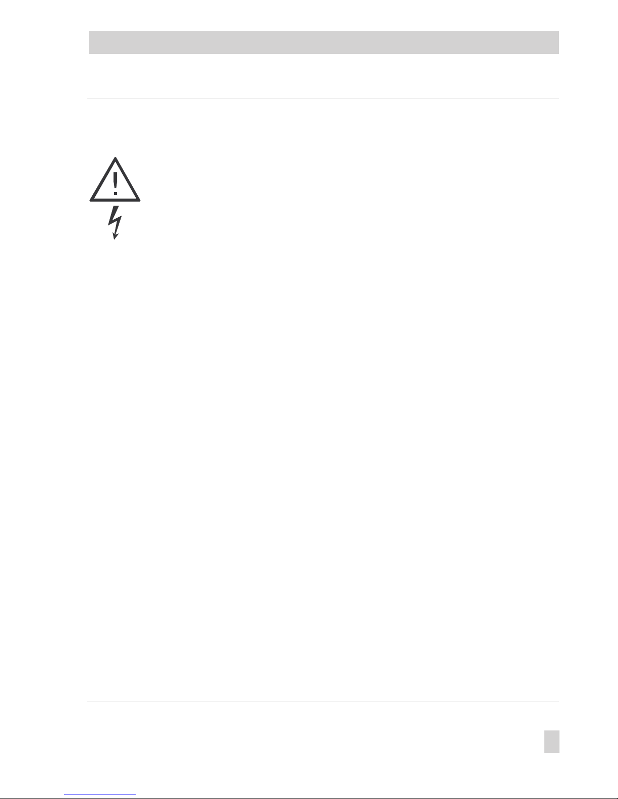
4. For valve sizes DN 15 to 25, unscrew
the guide nipple of the plug assembly (3)
using a socket wrench (order no.
1280-3001) or a self-made wrench
made from a Gedore screwdriver bit (IN
19-19), for example, by drilling a 17
mm hole with a 17 mm diameter into the
19 mm hexagon bit (Fig. 4). Then pull
out the guide nipple.
For valve sizes DN 32 to 50, unscrew
the stopper first. Then pull out the plug
assembly.
5. Thoroughly clean the seat and plug.
Check the control line and screw fitting
for any blockages. Should the plug be
damaged, replace the entire plug assem
-
bly with a new one.
6. To reassemble, proceed in reverse order.
Observe the tightening torques specified
in the table in Fig. 2.
4.3 Replacing the diaphragm
1. Unscrew the coupling nut and remove the
actuator from the valve.
2. Unscrew the control line (7).
3. Unscrew the screws (6.2). Remove the
bottom diaphragm case together with the
operating diaphragm (6.1) and dia
-
phragm plate.
4. Replace the diaphragm together with the
diaphragm plates with new ones.
5. To reassemble, proceed in reverse order.
Observe the tightening torques specified
in the table in Fig. 2. Prior to reattaching
the actuator, make sure that the diaphragm has been inserted properly in the
ring groove.
5 Nameplate
EB 3135-1 EN 9
Nameplate
17
Ø 17
SW 19
Fig. 4 · Socket wrench
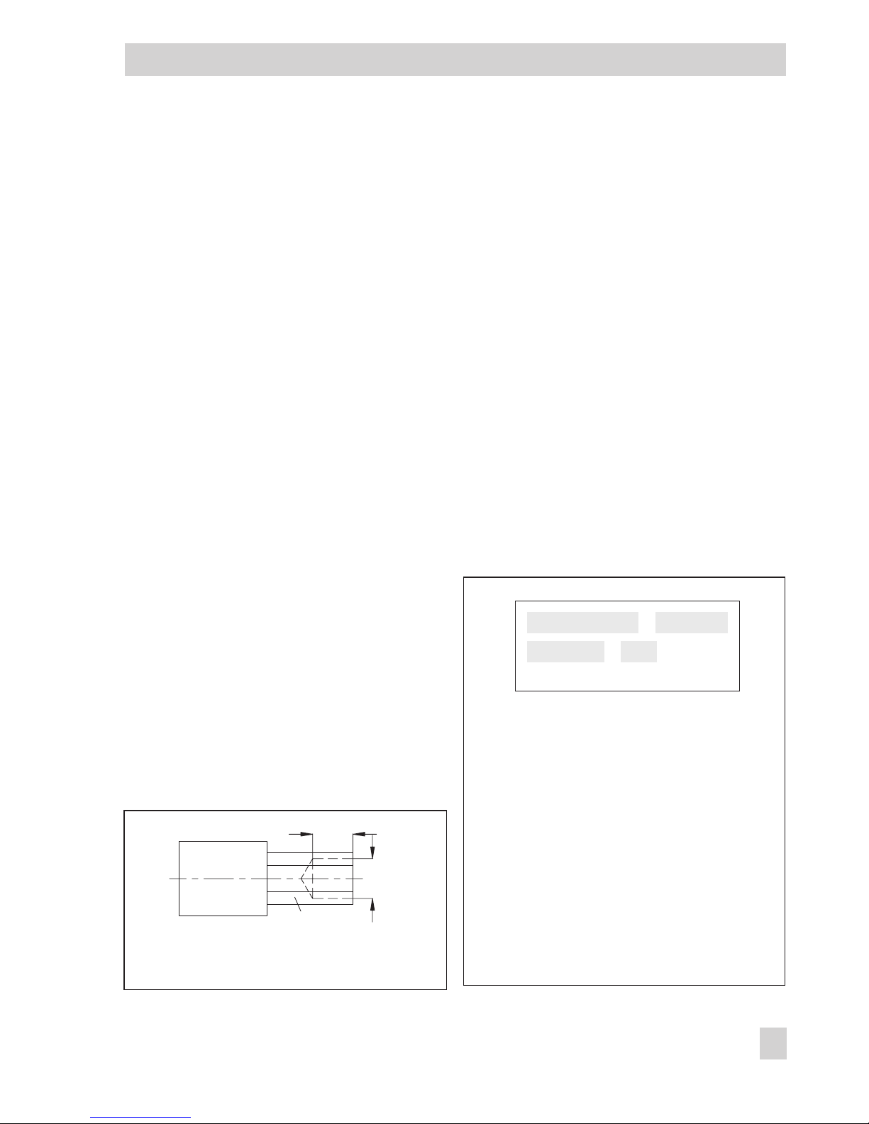
Fig. 5 · Labeling
1 Configuration ID
2 Type designation
3 Model number
4 Date of manufacture
In the other fields:
K
VS
or C
V
Upper differential pressure in bar or psi
Flow set point range in m³/h
Max. perm. temperature in °C or °F
Max. perm. differential pressureΔp
Nominal pressure PN or ANSI Class
1 2
3 4
Page 10

6 Troubleshooting
7 Customer inquiries
Should you have any inquiries, please submit
the following details:
4
Type and nominal size of the valve
4
Threaded or flanged connection
4
Model number
4
Upstream and downstream pressures
4
Flow rate in m³/h
4
Has a strainer been installed?
4
Installation drawing
10 EB 3135-1 EN
Troubleshooting
Fault Possible causes Solution
Flow rate
exceeds
adjusted set
point
Valve too large for
control task
Recalculate K
VS
and contact SAMSON.
Seat and plug leak Remove valve, clean seat and plug. If necessary,
replace plug (section 4.2).
Otherwise, return device for repair.
Operating diaphragm
defective
Replace diaphragm (section 4.3) or return device
for repair.
Control line blocked Remove and clean control line.
Flow set point
not reached
Incorrect set point range
selected
Check set point range and contact SAMSON.
Safety device, e.g. pressure
regulator, has been
triggered
Check plant, unlock safety device.
Electric actuator extended Check control signal from the electric control device.
Insufficient pressure drop
across the plant
Compare existing differential pressure in the plant
with the plant’s drag.
Min. diff. pressure = special diff. pressure +
(/ )
.
VK
VS
2
Strainer blocked Drain and clean filter of the strainer.
Valve installed against
direction of flow
Re-install valve such that direction of flow
corresponds to arrow on the body.
Control loop
hunts
Valve too large for
control task
Recalculate KVSand contact SAMSON.
Page 11

8 Dimensions and weights
EB 3135-1 EN 11
Dimensions and weights
Nominal size DN
15 20 25 32 40 50
Pipe external Ø d
21.3 26.8 32.7 42 48 60
Connection R
G ¾ G 1 G 1¼ G 1¾ G 2 G 2½
Width across flats SW
30 36 46 59 65 82
Length L
65 70 75 100 110 130
Height H
155 216
Height H1 PN 25
85 105 140
PN 16
105 – –
Standard versions
Welding ends L1
210 234 244 268 294 330
Weight, approx. kg
3.0 3.1 3.2 4.4 6.9 7.4
Special version with threaded ends (male thread)
Length L2
129 144 159 180 196 228
Male thread A
G ½ G ¾ G 1 G 1¼ G 1½ G 2
Weight, approx. kg
3.0 3.1 3.2 4.4 6.9 7.4
Special version with flanges PN 16/25 or version with flanged valve body (DN 32/40/50)
Length L3
130 150 160 180 200 230
Weight, approx. kg
3.6 4.3 4.9 9.1 10.4 11.9
146
6
dR
H
30
H1
L
L1
Ø116 (Ø160)
G
L3
L3
L
L2
L
A
SW
SW
SW
1
8
80
Fig. 6 · Dimensional drawings (dimensions in mm, values in parentheses for DN 40 and DN 50)
Connection nuts with welding ends Connection nuts with flanges Flanged body DN 32 to 50
Connection nuts with threaded ends Intermediate insulating piece
Page 12

SAMSON AG · MESS- UND REGELTECHNIK
Weismüllerstraße 3 · 60314 Frankfurt am Main · Germany
Phone: +49 69 4009-0 · Fax: +49 69 4009-1507
Internet: http://www.samson.de
EB 3135-1 EN
S/Z 2008-06
 Loading...