

Page 1
Supply Pressure Regulator
Type 4708
Mounting and
Operating Instructions
EB 8546 EN
Edition February 2005
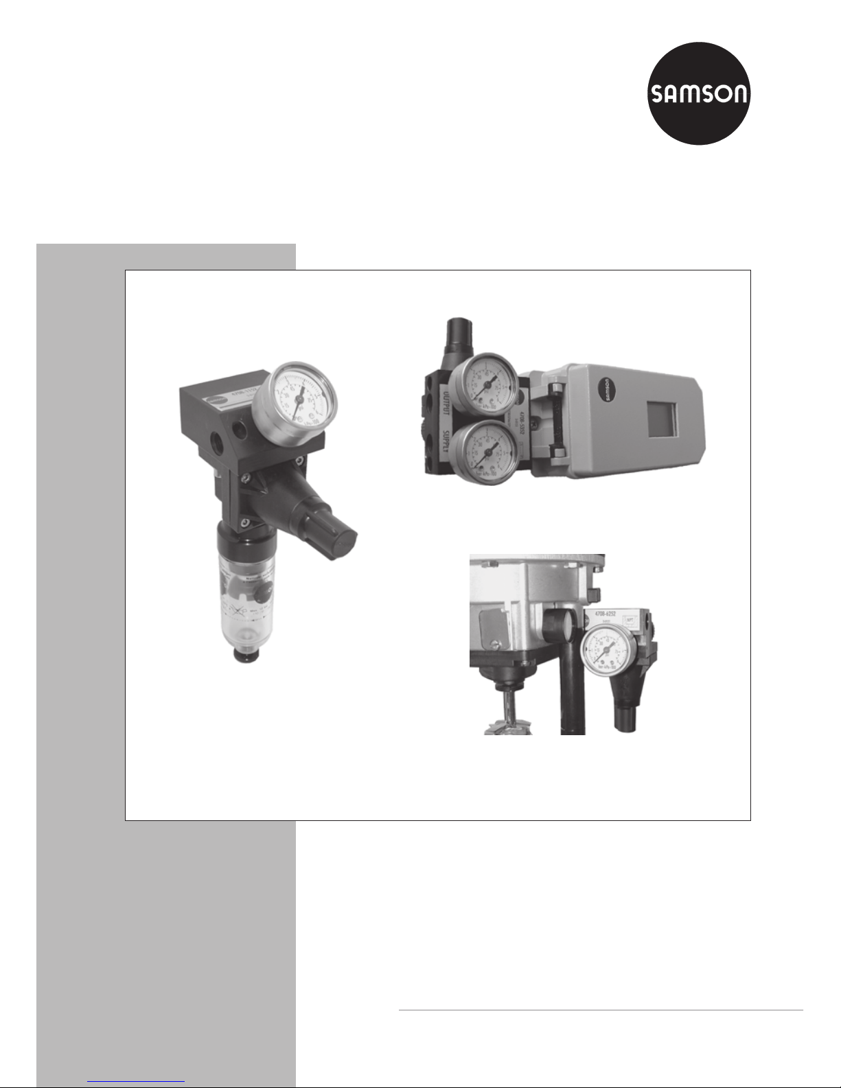
Fig. 1 · Supply pressure regulators
Type 4708-5352 on Type 3730 Positioner
Type 4708-6252 on Type 3372 Actuator
Type 4708-1152 with filter receptacle
Page 2

Contents Page
1 Design and principle of operation . . . . . . . . . . . . . . . . . . . 4
1.1 Versions . . . . . . . . . . . . . . . . . . . . . . . . . . . . . . . . 6
1.2 Technical data . . . . . . . . . . . . . . . . . . . . . . . . . . . . . 7
2 Mounting the supply pressure regulator . . . . . . . . . . . . . . . . 8
2.1 Compact supply pressure regulator . . . . . . . . . . . . . . . . . . . 8
2.1.1 Direction of flow . . . . . . . . . . . . . . . . . . . . . . . . . . . . 8
2.1.2 Turning the supply pressure regulator . . . . . . . . . . . . . . . . . . 9
2.2 Supply pressure regulators for attachment to positioners and actuators. . 10
3 Pneumatic connections . . . . . . . . . . . . . . . . . . . . . . . . 14
3.1 Pressure gauge . . . . . . . . . . . . . . . . . . . . . . . . . . . . 14
3.2 Additional connection for a solenoid valve . . . . . . . . . . . . . . . 15
4 Set point adjustment . . . . . . . . . . . . . . . . . . . . . . . . . 18
5 Maintenance . . . . . . . . . . . . . . . . . . . . . . . . . . . . . 18
6 Troubleshooting . . . . . . . . . . . . . . . . . . . . . . . . . . . 19
7 Accessories . . . . . . . . . . . . . . . . . . . . . . . . . . . . . . 19
8 Dimensions in mm . . . . . . . . . . . . . . . . . . . . . . . . . . 20
2 EB 8546 EN
Contents
Page 3
EB 8546 EN 3
Safety instructions
General safety instructions
4
The supply pressure regulator may only be mounted, started up or serviced
by fully trained and qualified personnel, observing the accepted industry
codes and practices. Make sure employees or third persons are not exposed
to any danger. All safety instructions and warnings in these mounting and
operating instructions, particularly those concerning assembly, start-up and
maintenance, must be observed.
4
Proper shipping and appropriate storage of the regulator are assumed.
Page 4

1 Design and principle of
operation
The supply pressure regulator is used to sup
-
ply pneumatic measuring and control equip
ment with a constant air supply.
The maximum 12 bar pressure of the com
pressed air network in a plant is reduced to
an adjustable minimum pressure of 0.2 to
1.6 bar or 0.5 to 6 bar.
At the input side, the supply pressure regu
lator is equipped with a filter cartridge with
a mesh size of 20 µm. In addition, the regu
-
lator can also be equipped with a filter re
ceptacle and a pressure gauge on the outlet
side.
The compressed air at the input flows across
the filter and through the free cross-sectional
area between the seat (1.1) and plug (1.2).
It leaves the output with a reduced pressure
depending on the plug position.
The output pressure to be controlled is trans
-
ferred via the bore (1.3) to the operating di
-
aphragm (2) where it is converted into a po
sitioning force. This force is used to move
the valve plug depending on the force of the
positioning spring (4).
Turning the set point screw (7) causes the
spring force to change and, as a result, the
required set point is adjusted.
The set point ranges of the supply pressure
regulator from 0.2 to 1.6 bar and 0.5 to
6 bar are determined by various tensions of
the installed positioning spring (4).
Condensed water contained in the compressed air can be collected and drained
when the filter cartridge (9) is mounted horizontally or the filter receptacle (12) is suspended downwards. The stopper (10) or
drain plug (15) can be unscrewed to drain
condensed water.
4 EB 8546 EN
Design and principle of operation
Page 5
EB 8546 EN 5
Design and principle of operation
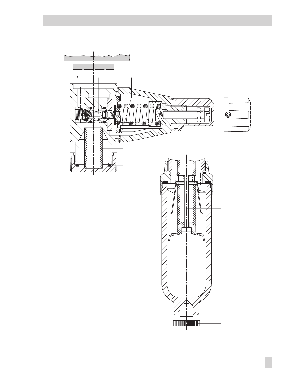
Fig. 2 · Sectional drawings
1.11 1.21.3 2 3 4 5 6 7 8
9
11
11.1
12.1
12
13
9
15
10
10.1
Adapter plate/connecting plate
Diverting gasket
1 Body
1.1 Seat
1.2 Plug
1.3 Bore
2 Operating diaphragm
3 Venting bore
4 Positioning spring
5 Cap
6 Lock nut
7 Set point screw
8 Adjustment knob
9 Filter cartridge
10 Stopper
11 Bushing
11.1 Gasket
12 Filter receptacle
12.1 Gasket
13 Screw
15 Drain plug
Page 6
1.1 Versions
Standard version Type 4708-
xxxx
Filter on aluminum basis without
filter receptacle
10
With plastic filter receptacle
11
With aluminum filter receptacle
12
Stainless steel supply pressure regulator
Filter on stainless steel basis with
stainless steel receptacle
13
With plastic filter receptacle
14
Without filter receptacle
17
Connection
G ¼
2
¼-18 NPT
5
Set point range 0.5 to 6 bar (8 to 90 psi)
Without pressure gauge
0
With pressure gauge,
completely free of copper
1
With pressure gauge,
copper-free housing
2
Set point range 0.2 to 1.6 bar (3 to 23 psi)
Without pressure gauge
3
With pressure gauge, comple
-
tely free of copper
4
With pressure gauge,
copper-free housing
5
Supply pressure regulator with adapter plate
for positioners
Type 3730, 3766, 3767, 3780,
3785, 3787
53
Type 3730, 3766, 3767, 3780,
3785, 3787
54
Type 4763/4765
55 0
Type 3760
57
Type 3761
58
Supply pressure regulator with adapter plate
for pneumatic actuators
Type 3277 (240 to 700 cm
2
)
with Type 3730, 3766, 3767,
3780, 3785 or 3787 Positioner
63 0
Type 3372
62
Filter without pressure gauge
Type 4708-
xxx0
Aluminum housing and plastic
filter receptacle
83 0
Aluminum housing and alu
-
minum filter receptacle
84 0
Stainless steel housing and
plastic filter receptacle
86 0
Stainless steel housing and
stainless steel filter receptacle
87 0
6 EB 8546 EN
Design and principle of operation
Page 7

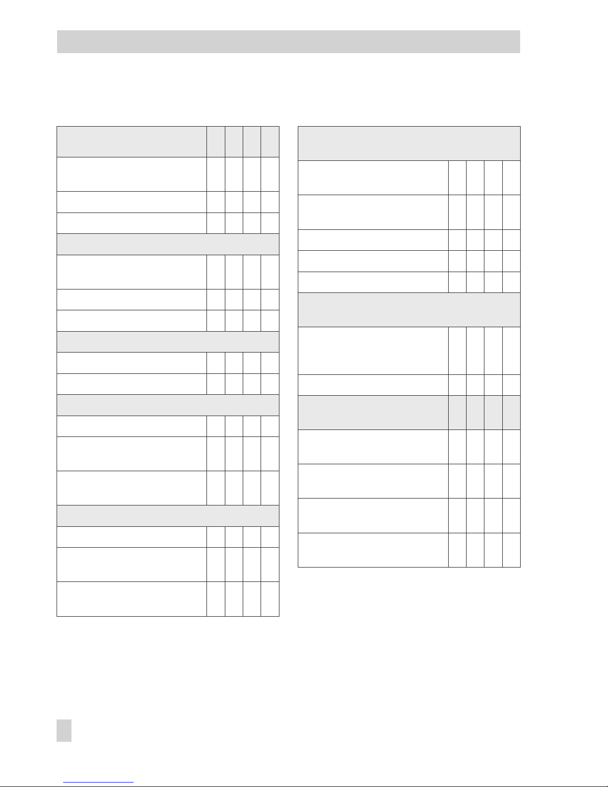
1.2 Technical data
EB 8546 EN 7
Design and principle of operation
Supply pressure regulator Type 4708-xx
Supply pressure
1 bar (15 psi) above the adjusted set point,
however, at least 1.6 bar (24 psi) · Max. 12 bar (180 psi)
Output pressure Adustable from 0 to 1.6 bar (0 to 24 psi) or 0 to 6 bar (0 to 90 psi)
Set point range 0.2 to 1.6 bar (3 to 24 psi) or 0.5 to 6 bar (8 to 90 psi)
Air consumption ≤ 0.05 mn
3
/h (with 7 bar supply air)
Permissible ambient
temperature
–20 to 70 °C
(–30 °C possible, but in this case, air consumption reaching up to 0.3 m
n
3
/h with
7 bar supply pressure)
Input pressure dependance < 0.01 bar / ∆p = 1 bar
Reversing error 0.1 bar to 0.4 bar (depending on the set point)
Hysteresis < 0.1 bar
Pressure gauge Ø40
indication range
0 to 1.6 bar (0 to 24 psi) or 0 to 6 bar (0 to 90 psi)
Connection G 1/8
Type 4708- 10 11 12 13 14 17 53 54 55
Weight, approx. 0.48 0.58 0.66 1.65 1.2 1.0 0.68 0.95 0.37
Type 4708- 57 58 62 63 83 84 86 87
Weight, approx. 0.47 0.4 0.4 0.87 0.24 0.32 0.59 0.95
Materials
Body Polyamide, glass fiber reinforced
Adapter plate Aluminum alloy, anodized black
Stopper and gasket Polyamide, glass fiber reinforced and NBR
Cover Polyamide, glass fiber reinforced
Cap Polyamide, glass fiber reinforced
Plug Polyamide, glass fiber reinforced and polyoxymethylene
Plug sealing NBRT and VMQ
Diaphragm NBR
Diaphragm plate Polyamide, glass fiber reinforced
Filter cartridge Polypropylene
Pressure gauge housing
connection
Stainless steel
St. steel (version free of copper)
Brass, nickel-plated
Page 8
2 Mounting the supply pressure
regulator
To prevent excessive amounts of condensed
water from collecting, the distance between
the compressor and supply pressure regula
tor should be kept as short as possible.
Make sure the drain plug faces downwards
in versions with a filter receptacle.
2.1 Compact supply pressure
regulator
The supply pressure regulator can either be
mounted directly in the pipeline of the air
supply or on rails or brackets using the corresponding mounting parts (see table in
section 7 on page 19).
Observe the direction of flow of the supply
air. An arrow on the nameplate indicates
the direction.
2.1.1 Direction of flow
In the compact supply pressure regulators
4708-10xx/-11xx/-14xx and -17xx the
direction of flow can be changed as follows:
1. Unscrew both fixing screws and lift the
supply pressure regulator off its connect
-
ing plate.
2. Remove the diverting gasket, turn it
180 degrees and reposition it as shown
in Fig. 3.
Note! The long rubber finger of the gas
ket must always point in the direction of
the regulator output.
3. Screw the supply pressure regulator tight
onto the connecting plate.
4. Stick the enclosed adhesive label over
the arrow of the nameplate, ensuring the
arrow indicates that the supply air flows
in the opposite direction.
8 EB 8546 EN
Mounting the supply pressure regulator
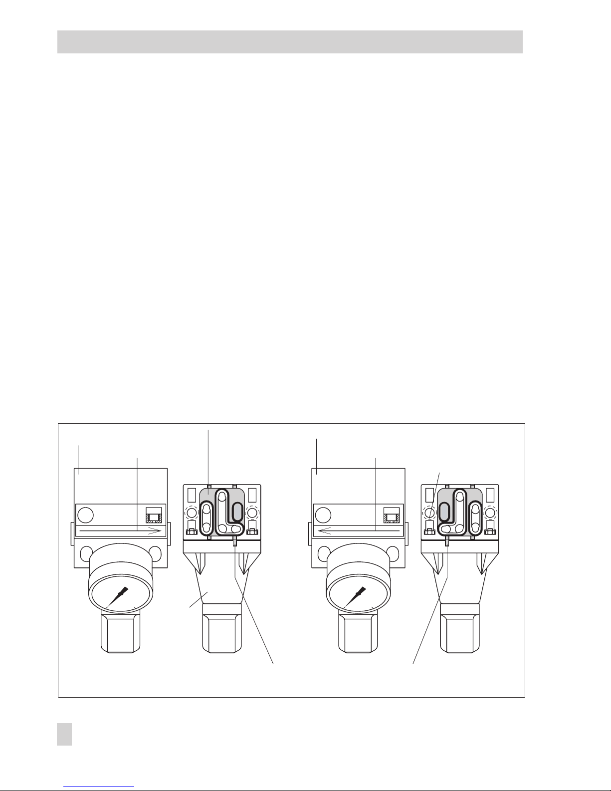
Fig. 3 · Changing the direction of flow in compact supply pressure regulators
G
4708-112.
0
6
3-....
0
6
3-....
4708-112.
G
Connecting plate
Standard label
Gasket
Connecting plate
Label with arrow
Fixing screws
Long rubber finger always pointing towards the regulator output
Supply
pressure
reglulator
Page 9

2.1.2 Turning the supply pressure
regulator
The supply pressure regulator can be turned
on its connecting plate to allow the set point
adjuster to face either up or down.
1. Unscrew both fixing screws and lift the
supply pressure regulator off its connect
-
ing plate.
2. Pull the diverting gasket out of the regu
-
lator and keep it in this position.
3. Turn the regulator 180 degrees and re
insert the gasket. In this way, you keep
the bore assignment of the gasket for
supply air input and regulator output.
Note! The long rubber finger of the gas
ket must always point in the direction of
the regulator output (reduced supply
pressure).
4. Screw the regulator tight onto the con
-
necting plate.
EB 8546 EN 9
Mounting the supply pressure regulator
Fig. 4 · Turning the supply pressure regulator on its connecting plate or adapter plate
Supply air input
Connecting plate or adapter plate
Supply air input
(Supply) >
Regulator facing downward
Diverting gasket
Long rubber finger
always pointing
towards output
Regulator facing upward
Fixing screws
Regulator output
Diverting gasket
Front and back view
Regulator output (long rubber finger)
Supply air input
depending on the
position of the
gasket
Page 10

2.2 Supply pressure regulators
for attachment to positioners
and actuators
The supply pressure regulator versions in
-
tended for attachment to positioners and ac
tuators are equipped with various adapter
plates for the attachment.
If required, the installation position of the
supply pressure regulator can be changed
by turning it 180° on its adapter plate to al
low the adjustment knob to face either up or
down. This applies particularly for
positioners which can be attached either to
the left or right side of the valve yoke to de
termine the operating direction and fail-safe
action of the actuator.
To turn the supply pressure regulator, proceed as described for the compact supply
pressure regulator in section 2.1.2. The regulator is turned on its adapter plate instead
of on the connecting plate.
Regulators for Types 3730/3766/3767/
3780/3785/3787 Positioners
Type 4708-53xx for Type 3271 Actuator up
to 700 cm
2
and Type 3277 Actuator with
120 cm
2
as well as 240 to 700 cm2with
hooked-up accessories
1. Insert the gasket (2) into the recess of the
adapter plate (1).
2. Place the supply pressure regulator on
the positioner on the side where the
pneumatic connections SUPPLY and
OUTPUT are located. Screw tight using
both M5 screws (3).
3. Close the spare connections with
stoppers (4) to prevent dirt from entering
the device.
Type 4708-54xx for Type 3271 Actuator
with 1400 and 2800 cm
2
or single-acting
rotary actuators.
Proceed to mount as for Type 4708-53xx.
10 EB 8546 EN
Mounting the supply pressure regulator
Fig. 5 · Attachment onto positioners
Type 4708-53xx
Type 4708-54xx
73
192
109
4708-535.
6
0
0
6
NPT
1
2
3
4
1
Page 11

Type 4708-55xx for Type 4763 and
Type 4765 Positioner
1. Screw the special nuts (5) into the con
-
necting bores of the positioner.
2. Insert the gasket (2) into the recess of the
adapter plate (1).
3. Push the special hollow screws (6) for
SUPPLY and (7) for OUTPUT into the
connecting bores of adapter plate (1).
4. Place the supply pressure regulator onto
the positioner and screw it tight using
both special screws.
5. Close the spare connections with
stoppers (4) to prevent dirt from entering
the device.
Type 4708-57xx for Type 3760 Positioner
The attachment for a positioner mounted on
the left side of the valve yoke (seen from the
black switchover plate) is shown. For a
positioner mounted on the right side, the
adapter plate is attached in the same way,
except the supply pressure regulator must be
turned by 180° (see bottom of page 23).
1. Screw the special nuts (5) into the con
-
necting bores of the positioner.
2. Insert the O-rings (9) into the recess of
the adapter plate (1).
3. Push the special hollow screws (6) for
SUPPLY and (7) for IN. SIGNAL into the
connecting bores of the adapter plate
(1).
4. Place the supply pressure regulator onto
the positioner and screw it tight using
both special screws.
5. Close the spare connections with stop
-
pers (4) to prevent dirt from entering.
EB 8546 EN 11
Mounting the supply pressure regulator
Fig. 6 · Attachment onto positioners
6
0
S
A
M
S
O
N
4
7
6
3
4708-552.
6
0
G
1
7
6
5
5
2
1
4
4
1
7
9
6
1
5
5
< Switchover
plate
Page 12

Type 4708-58xx for Type 3761 Positioner
1. Screw the special nut (5) into the SUPPLY
connecting bore of the positioner.
2. Push the special hollow screw (6) into
the connection bore of the adapter plate
(1).
3. Insert the O-ring (9). Position the supply
pressure regulator and screw it tight to
the positioner with the special screw.
4. Close the spare connections with
stoppers (4) to prevent dirt from entering
the device.
Type 4708-63xx for Type 3277 Actuator
Before attaching the supply pressure regulator, check whether the tongue of the gasket
(1.2) is aligned at the adapter block (1) in
such a way that the actuator symbol (1.3)
indicating “Actuator stem extends” or “Actuator stem retracts” matches the fail-safe action of the actuator.
If this is not the case, unscrew the three fixing screws (3), lift off the cover plate (1.1)
and turn the gasket (1.2) by 180° and rein
-
sert it.
1. Place the adapter block on the positioner
and actuator yoke and fasten using fix
-
ing screws (2).
12 EB 8546 EN
Mounting the supply pressure regulator
Fig. 7 · Attachment of supply pressure regulators
1
38
2
38
G
O
utput
O
utput
S
Input
6
5
4
3
2
1
0
27
1
6
9
4
1
5
2
3
1
1.1
1.2
1.3
G3/8
06
06
Page 13

Type 4708-62xx for Type 3372 Actuator
1. Screw the special nut (5) into the SUPPLY
connecting bore of the actuator.
2. Push the special hollow screw (6) into
the connecting bore of the adapter
plate.
3. Insert the O-ring (9). Position the supply
pressure regulator and screw it tight
onto actuator using the special screw.
4. Close the spare connections with
stoppers (4) to prevent dirt from entering
the device.
EB 8546 EN 13
Mounting the supply pressure regulator
Fig. 8 · Attachment to Type 3372 Actuator
1
9
5
6
4
1
6
5
9
4
Page 14

3 Pneumatic connections
The pneumatic connections are designed ei
ther as G 1/4 or 1/4 NPT-18 threads. In
compact supply pressure regulators, an ar
-
row on the adhesive label indicates the di
-
rection from the supply air input to the out
-
put.
In supply pressure regulators with two con
necting bores in the adapter plate (Figs. 5
and 6, top), the supply air connection is
marked SUPPLY. The positioner's output sig
nal is led in these versions via the OUTPUT
bore through the adapter plate to the actua
tor.
3.1 Pressure gauge
Mount the pressure gauge in such a way
that there is a 2-3 mm gap between the lock
nut and pressure gauge's square end after
tightening the lock nut (20).
In the compact versions 4708-12xx/13xx,
make sure additionally that the stopper (23)
is only screwed in to the point where it be
comes aligned with the housing, otherwise
the gaskets (21, 22) will be damaged. Each
gasket is assigned either to the pressure
gauge or to the stopper and must be
changed correspondingly if you change the
location of the pressure gauge and stopper
to the other side.
14 EB 8546 EN
Pneumatic connections
Fig. 9 · Pressure gauge attachment, e.g. with Type 4708-12xx/13xx Supply Pressure Regulators
20 22
2...3 mm 0 mm
21 23
Page 15

3.2 Additional connection for a
solenoid valve
An intermediate plate must be mounted be
tween the connecting or adapter plate and
the regulator to connect a solenoid valve.
The reduced supply pressure of the supply
pressure regulator is additionally led to the
threaded connection at the side via the cor
-
responding bores in the intermediate plate.
All supply pressure regulators have the
same intermediate plate, except for Type
4708-57xx, designed for attachment to
Type 3760 Positioner (Fig. 12), its interme
diate plate has a different bore assignment
for the air ducts. All versions can be ordered
made of aluminum or stainless steel and
with either G or NPT threads. See section 7
for more details.
EB 8546 EN 15
Pneumatic connections
Fig. 10 · Mounting an intermediate plate for Types 3730/3766/3767/3780 Positioners
1
1.1
A
A
A
A
E
SUPPLY
2
2.1
3
4
4.1
E
E
E
Output for
reduced supply air
Intermediate plate (2) with
additional connection
Page 16

Mounting the intermediate plate
1. Remove the fixing screws and lift the
supply pressure regulator (4) together
with the diverting gasket (3) off the
adapter plate (1).
Make sure you do not change the posi
tion of the diverting gasket in the supply
pressure regulator.
Note! The long rubber finger of the diverting
gasket (3) must always point in the direction
of the regulator output (reduced supply air).
See Figs. 10, 11, 12.
2. Insert O-rings (2.1) in the bores of the
intermediate plate (2).
3. Place the intermediate plate onto the
adapter plate in such a way that the
three holes located next to one another
16 EB 8546 EN
Pneumatic connections
Fig. 11 · Mounting an intermediate plate on Type 3372 Actuator
1
1.1
E
A
M
A
2
2.1
3
4
4.1
A
A
E
A
E
A
E
Intermediate
plate (2)
Supply air input
Output for
reduced supply air
Page 17

are positioned over both 5 mm holes on
the adapter plate and the bores (1.1) for
the fixing screws are aligned.
4. Place the supply pressure regulator (4)
with the diverting gasket (3) onto the in
termediate plate (2). Insert the longer
fixing screws and screw tight.
EB 8546 EN 17
Pneumatic connections
Fig. 12 · Mounting an intermediate plate on Type 3760 Positioner
SUPPLY
A
M
A
2
1
2.1
1.1
E
E
3
E
4
4.1
E
A
A
A
A
Page 18

4 Set point adjustment
(Fig. 2)
Depending on the version, the set point of
the supply pressure regulator can be ad
justed either at the adjustment knob (8), or
after screwing off the cap (5), at the set
point screw (7).
4
Turning the knob or screw clockwise in
creases the output pressure and turning it
counterclockwise reduces the output
pressure.
4
Use the lock nut (6) to secure the setting.
Note!
When using the version with the adjustment
knob (8) to adjust the set point, make sure
that the Phillips screws are screwed tight to
prevent the knob from coming loose due to
possible vibrations.
5 Maintenance
(Fig. 2)
We recommend you check the filter as often
as possible.
Drain condensed water that has collected by
removing the stopper (10) or by unscrewing
the drain plug (15) about half a turn.
When faults occur, e.g. a pressure drop, un
-
screw the stopper (10) or the filter recepta
-
cle (12) and replace the filter cartridge (or
der no. 8504-9027).
Prior to carrying out any maintenance work,
shut off the air supply!
In the version with a filter receptacle, screw
the fixing screw (13) tight so that the filter
cartridge sits properly. Replace the gasket
(12.1) order no. 0439-0061, if necessary.
In the versions 4708-11xx/14xx, do not unscrew the bushing (11), if at all possible. If,
however, you needed to unscrew it, you can
replace the gasket (11.1) order no.
0439-0287 as well.
If there is any leakage at the stopper (10),
the entire stopper and seal ring (10.1) order
no. 1099-3871 must be replaced.
18 EB 8546 EN
Set point adjustment
Page 19

6 Troubleshooting
4
Leakage between supply pressure regu
lator and adapter plate:
Check whether the diverting gasket
(Figs. 3 and 4) is installed and both fix
ing screws are tightened properly.
4
Excessive blow-off over the venting bore
(3 in Fig. 2):
Check whether the diverting gasket
(Figs. 3 and 4) is installed correctly.
4
The air supply decreases and the output
pressure drops:
Check the filter cartridge (9 in Fig. 2) for
dirt and make sure the set point is correctly adjusted.
7 Accessories
EB 8546 EN 19
Troubleshooting
Accessories Order no.
Mounting parts for mounting on rail acc. to EN 50022
acc. to EN 50035
1400-7341
1400-7342
Mounting parts for mounting on bracket for Type 3271Actuator 1400-7343
Intermediate plate for additional connection with Types 4708-10xx/-11xx/-53xx/-55xx/-58xx/-62xx/-63xx
Aluminum with G ¼ thread
Aluminum with 1/4 NPT thread
Stainless steel with G ¼ thread
Stainless steel with 1/4 NPT thread
1400-7400
1400-7404
1400-7402
1400-7406
Intermediate plate for additional connection with Type 4708-57.. Supply Pressure Regulator
Aluminum with G ¼ thread
Aluminum with 1/4 NPT thread
Stainless steel with G ¼ thread
Stainless steel with 1/4 NPT thread
1400-7401
1400-7405
1400-7403
1400-7407
Adjustment knob for set point adjustment 1400-7408
Nut for panel mounting 1400-7725
Page 20

8 Dimensions in mm
20 EB 8546 EN
Dimensions in mm
Type 4708-10xx/17xx Supply Pressure Regulator
Type 4708-11xx/14xx Supply Pressure Regulator
504339
78
19
50
190(214)
19
50
43
78
50
78 (102)
90
126
60
44
G
4708-112.
3-....
0
6
Supply pressure regulators with
intermediate plate for additional
connection have an overall height
increased by 24 mm.
The dimensions in parentheses
apply.
Mounting bracket
(accessories)
Page 21

EB 8546 EN 21
Dimensions in mm
06
06
80
65(89)
Output
Supply
56
42
57
99
44 44
59
42
2299
15119
125
28
70
14
4708-535.
NPT
0
6
1
2
3
4
5
Type 4708-12xx/13xx Supply Pressure Regulator
Type 4708-83xx/84xx/86xx/87xx
Supply Pressure Regulator
Type 4708-53xx Supply Pressure Regulator
for Types 3730/3766/3767/3780/3785/3787 Positioners
Page 22

22 EB 8546 EN
Dimensions in mm
43 180
109
132
45
121
88
G3/8
06
06
Type 4708-54xx Supply Pressure Regulator
for Types 3730/3766/3767/3780/3785/3787 Positioners
Type 4708-55xx
for Types 4763/4765 Positioners
Output
Supply
66 (90)55
25
120
G
6
0
S
A
M
S
O
N
4
7
6
3
4708-552.
6
0
Page 23

EB 8546 EN 23
Dimensions in mm
99 122
133 (157)
Supply
Input
Signal
Input
Signal
Supply
927
927
47
120
Type 4708-57xx Supply Pressure Regulator
for Type 3760 Positioner
Page 24

24 EB 8546 EN
Dimensions in mm
43 180
109
132
45
121
88
G3/8
06
06
Type 4708-63xx
for Type 3277 Actuator
Attachment on left or right
60
(84)
Supply
56
30
93
1
38
2
38
G
Output
Output
S
Input
6
5
4
3
2
1
0
SAMSON
27
Type 4708-58xx
for Type 3761 Positioner
Page 25

EB 8546 EN 25
Dimensions in mm
0
6
G
4
7
0
8
-
6
2
2
X
Supply
19 94
111(135)
113
60
Supply
111
Type 4708-6221
for Type 3372-031x Actuator
Page 26

SAMSON AG · MESS- UND REGELTECHNIK
Weismüllerstraße 3 · 60314 Frankfurt am Main · Germany
Phone: +49 69 4009-0 · Fax: +49 69 4009-1507
Internet: http://www.samson.de
EB 8546 EN
S/Z 2005-03
 Loading...