

Page 1
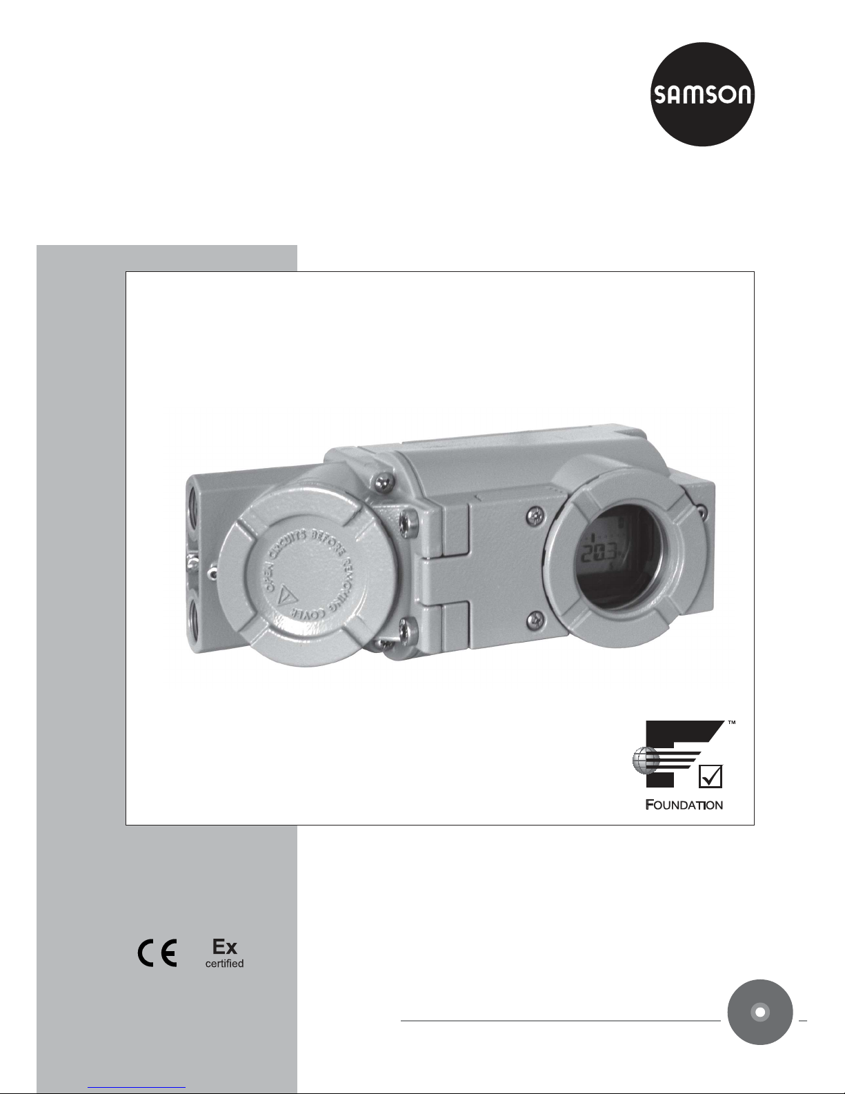
Series 3731
Type 3731-5
Electropneumatic Ex d Positioner
with FOUNDATION™fieldbus communication
Mounting and
Operating Instructions
EB 8387-5 EN
Firmware version R 1.4x
Edition
March 2016
Fig. 1 · Type 3731-5
EB + CD
Page 2
2 EB 8387-5 EN
DANGER!
indicates a hazardous situation which, if not
avoided, will result in death or serious injury.
WARNING!
indicates a hazardous situation which, if not
avoided, could result in death or serious
injury.
NOTICE
indicates a property damage message.
Note: Supplementary explanations, informa
-
tion and tips
Definitions of the signal words used in these instructions
Page 3

Contents
1 Important safety instructions . . . . . . . . . . . . . . . . . . . . . . 5
2 Article code . . . . . . . . . . . . . . . . . . . . . . . . . . . . . . 6
3 Design and principle of operation. . . . . . . . . . . . . . . . . . . . 7
3.1 Additional equipment . . . . . . . . . . . . . . . . . . . . . . . . . . 8
3.2 Communication . . . . . . . . . . . . . . . . . . . . . . . . . . . . . 9
3.2.1 Configuration using TROVIS-VIEW software . . . . . . . . . . . . . . . 9
3.2.2 Configuration using the NI-BUS™ Configurator
. . . . . . . . . . . . . . . . . 9
3.3 Technical data. . . . . . . . . . . . . . . . . . . . . . . . . . . . . 10
4 Attachment to the control valve – Mounting parts and accessories . . . 13
4.1 Direct attachment . . . . . . . . . . . . . . . . . . . . . . . . . . . 15
4.1.1 Type 3277-5 Actuator . . . . . . . . . . . . . . . . . . . . . . . . . 15
4.1.2 Type 3277 Actuator . . . . . . . . . . . . . . . . . . . . . . . . . . 18
4.2 Attachment according to IEC 60534-6 (NAMUR) . . . . . . . . . . . . 20
4.3 Attachment to Type 3510 Micro-flow Valve. . . . . . . . . . . . . . . 22
4.4 Attachment to rotary actuators . . . . . . . . . . . . . . . . . . . . . 24
4.5 Reversing amplifier for double-acting actuators . . . . . . . . . . . . . 26
4.5.1 Reversing amplifier (1079-1118 or 1079-1119) . . . . . . . . . . . . 26
4.6 Required mounting parts and accessories. . . . . . . . . . . . . . . . 28
5 Connections . . . . . . . . . . . . . . . . . . . . . . . . . . . . . . 31
5.1 Pneumatic connections . . . . . . . . . . . . . . . . . . . . . . . . . 31
5.1.1 Signal pressure gauges . . . . . . . . . . . . . . . . . . . . . . . . 32
5.1.2 Supply pressure . . . . . . . . . . . . . . . . . . . . . . . . . . . . 32
5.1.3 Signal pressure (output) . . . . . . . . . . . . . . . . . . . . . . . . 32
5.2 Electrical connections . . . . . . . . . . . . . . . . . . . . . . . . . 33
5.2.1 Establishing communication . . . . . . . . . . . . . . . . . . . . . . 37
6 Operator controls and readings . . . . . . . . . . . . . . . . . . . . 38
6.1 Rotary pushbutton. . . . . . . . . . . . . . . . . . . . . . . . . . . 38
6.2 Serial interface . . . . . . . . . . . . . . . . . . . . . . . . . . . . 38
6.3 Readings on display. . . . . . . . . . . . . . . . . . . . . . . . . . 38
7 Start-up – Settings. . . . . . . . . . . . . . . . . . . . . . . . . . . 40
7.1 Adapting the display. . . . . . . . . . . . . . . . . . . . . . . . . . 40
7.2 Limiting the signal pressure. . . . . . . . . . . . . . . . . . . . . . . 40
7.3 Checking the operating range of the positioner . . . . . . . . . . . . . 41
7.4 Determining the fail-safe position. . . . . . . . . . . . . . . . . . . . 42
7.5 Positioner initialization. . . . . . . . . . . . . . . . . . . . . . . . . 43
7.5.1 Initialization based on MAX maximum range . . . . . . . . . . . . . 44
EB 8387-5 EN 3
Contents
Page 4

7.5.2 Initialization based on NOM nominal range . . . . . . . . . . . . . . 45
7.5.3 Initialization based on MAN manually selected range . . . . . . . . . 47
7.5.4 SUB substitute calibration . . . . . . . . . . . . . . . . . . . . . . . 48
7.6 Zero calibration . . . . . . . . . . . . . . . . . . . . . . . . . . . . 52
7.7 Reset to default values . . . . . . . . . . . . . . . . . . . . . . . . 53
8 Operation. . . . . . . . . . . . . . . . . . . . . . . . . . . . . . . 54
8.1 Enabling and selecting parameters . . . . . . . . . . . . . . . . . . 54
8.2 Operating modes . . . . . . . . . . . . . . . . . . . . . . . . . . . 55
8.2.1 Automatic and manual operating modes . . . . . . . . . . . . . . . . 55
8.2.2 SAFE – Fail-safe position. . . . . . . . . . . . . . . . . . . . . . . . 56
8.3 Malfunction/maintenance alarm . . . . . . . . . . . . . . . . . . . . 56
8.3.1 Confirming error messages . . . . . . . . . . . . . . . . . . . . . . 57
9 Maintenance . . . . . . . . . . . . . . . . . . . . . . . . . . . . . 58
10 Servicing explosion-protected devices . . . . . . . . . . . . . . . . . 58
11 Code list . . . . . . . . . . . . . . . . . . . . . . . . . . . . . . . 59
12 Dimensions in mm. . . . . . . . . . . . . . . . . . . . . . . . . . . 78
12.1 Fixing levels according to VDI/VDE 3845 (September 2010) . . . . . . 80
13 Appendix . . . . . . . . . . . . . . . . . . . . . . . . . . . . . . . 82
13.1 Selecting the valve characteristic . . . . . . . . . . . . . . . . . . . . 82
Test certificates . . . . . . . . . . . . . . . . . . . . . . . . . . . . 84
Index . . . . . . . . . . . . . . . . . . . . . . . . . . . . . . . . . 90
4 EB 8387-5 EN
Contents
Note concerning these Mounting and Operating Instructions
These instructions EB 8387-5 describe the mounting, start up and on-site operation of the
Type 3731-5 Positioner.
You can find additional information on the enclosed CD-ROM (CD 8387-5) or on the Internet
at http://www.samson.de.
Page 5
1 Important safety instructions
For your own safety, follow these instructions concerning the mounting, start up and opera
-
tion of the positioner:
4
The positioner may only be mounted, started up or operated by trained and experi
enced personnel familiar with the product.
According to these Mounting and Operating Instructions, trained personnel is referred
to as individuals who are able to judge the work they are assigned to and recognize
possible dangers due to their specialized training, their knowledge and experience as
well as their knowledge of the relevant standards.
4
Explosion-protected versions of this positioner may only be operated by personnel
who have undergone special training or instructions or who are authorized to work
on explosion-protected devices in hazardous areas.
4
Any hazards that could be caused by the process medium, the operating pressure, the
signal pressure or by moving parts of the control valve are to be prevented by means
of the appropriate measures.
4
If inadmissible motions or forces are produced in the actuator as a result of the supply
pressure level, it must be restricted by means of a suitable supply pressure reducing
station.
To avoid damage to any equipment, the following also applies:
4
Proper shipping and appropriate storage are assumed.
4
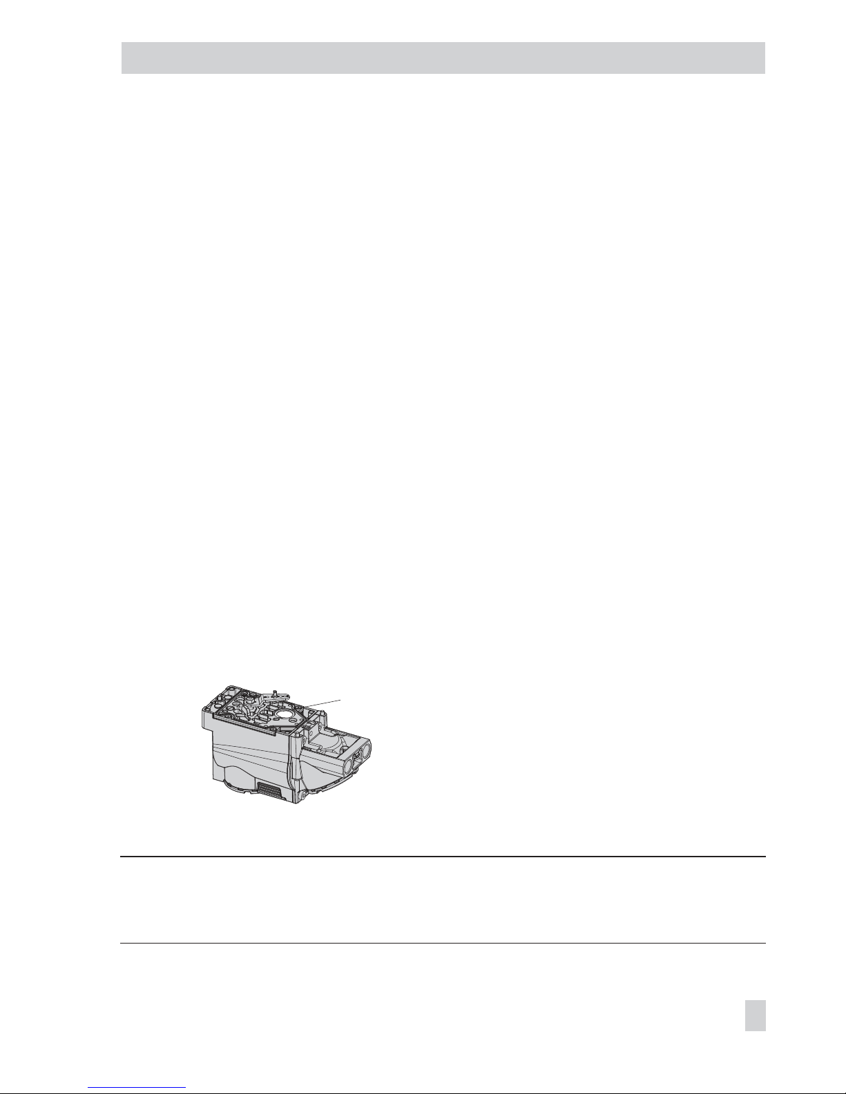
Do not operate the positioner with the back of the positioner/vent opening facing up
-
wards.
4
Do not ground electric welding equipment near to the positioner.
Note: The device with a CE marking fulfills the requirements of the Directives 94/9/EC and
2004/108/EC.
The Declaration of Conformity is included on the enclosed CD-ROM.
EB 8387-5 EN 5
Important safety instructions
Vent opening
Page 6

2 Article code
Positioner Type 3731 - 5 x x x x x x 0 0 0 x 1 x 0 0 0
With LCD, autotune, F
OUNDATION™ fieldbus
Explosion protection
ATEX:
II 2G Ex d IIC T6,T5,T4 Gb; II 2G Ex de IIC T6,T5,T4 Gb; II 2D Ex tb IIIC T80°C DB IP66
II 2G Ex d IIC T6 Gb; II 2G Ex de IIC T6 Gb; II 2D Ex tb IIIC IP65 T80°C
2 1
FM/CSA:
Class I, Div. 1+2, Groups B, C, D; Class I, Zone 1, Groups IIB+H2;
Class I, Div. 1+2 Groups E, F, G; Class III/
Class I, Zone 1, Group IIB+H2 T4...T6; Class I, Div. 1+2, Groups B, C, D T4...T6;
Class II, Div. 1, Groups E, F, G
2 3
JIS: Ex d IIC T6 2 7
Options (additional equipment)
Without 0 0
Binary input 0 3
Forced venting 0 5
Diagnostics
EXPERT 1
EXPERT+/PST 2
Electrical connections
2x M20 x 1.5 1
2x ½ NPT 2
Explosion-protection certificates
As specified in Explosion protection 0
IECEx: Ex d IIC T6, T5, T4 Gb; Ex d e IIC T6, T5, T4 Gb; Ex tb IIIC T80°C Db IP66 2 1 2
GOST: 1Ex d IIC T6/T5/T4 Gb X; 1Ex d e IIC T6/T5/T4 Gb X; Ex tb IIIC T 80°C Db X 2 1 3
Special applications
Without 0
Positioner compatible with paint (IP 41/NEMA 1) 1
Special version
Without 0 0 0
6 EB 8387-5 EN
Article code
Page 7

3 Design and principle of
operation
The electropneumatic Ex d positioner is at
tached to pneumatic control valves. It is used
to assign the valve stem position (controlled
variable x) to the control signal (reference
variable w). The input signal received from
a control system is compared to the travel or
rotational angle of the control valve, and a
signal pressure (output variable y) is pro
-
duced for the pneumatic actuator.
The positioner basically consists of an
electrical travel sensor system (2), an analog
i/p converter (6) with downstream air ca
pacity booster (7) and the electronic unit
with a microcontroller (5).
In case of a system deviation, the actuator is
either vented or filled with more air. The sig
nal pressure supplied to the actuator can be
limited to 1.4 bar, 2.4 bar or 3.7 bar by
software or on site at the positioner.
EB 8387-5 EN 7
Design and principle of operation
%
S
mm
%
mm
w
x
G
PD
Serial
Interface
16
22
20
23
2
4
17
5
19
3
6
7
8
1
9
x
y
Fig. 2 · Functional diagram
1 Control valve
2 Travel sensor
3 PD controller
4 IEC 61158-2
interface module
5 Microcontroller
6 i/p converter
7 Air capacity booster
8 Pressure regulator
9 Flow regulator
16 Display
17 Forced venting control
(optional)
19 D/A converter
20 Serial interface (SSP)
22 Rotary pushbutton
23 Binary input
(optional)
FOUNDATION
™
fieldbus
IEC 61158-2
Page 8

A constant air stream to the atmosphere is
created by the flow regulator (9) with a
fixed set point. The air stream is used to
purge the inside of the housing as well as to
optimize the air capacity booster (7). The
i/p converter (6) is supplied with a constant
upstream pressure by the pressure regulator
(8) to make it independent of the supply
pressure.
All parts are enclosed in an Ex d housing.
The electrical cables are connected over a
separate terminal compartment which also
has Ex d protection.
The standard EXPERT diagnostics are inte
-
grated into the positioner. It provides infor
-
mation on the positioner and generates di
agnostic and status messages, which allow
faults to be pinpointed quickly.
The positioner is suitable for the following
types of attachment using the corresponding
accessories:
4
Direct attachment to SAMSON
Type 3277 Actuator: Section
4.1
4
Attachment to actuators acc. to
IEC 60534-6 (NAMUR): Section 4.2
4
Attachment to Type 3510 Micro-flow
Valve: Section 4.3
4
Attachment to rotary actuators acc. to
VDI/VDE 3845: Section 4.4
3.1 Additional equipment
Binary input
The positioner has an optional binary input.
Connected at terminals A-B:
The binary input for DC voltage signals al
lows process information to be exchanged
over the FOUNDATION™fieldbus network.
Connected at terminals B-C:
This input connects a floating contact which
is powered by the positioner. The switching
state of the binary input can be indicated
over the F
OUNDATION
™
fieldbus network.
Forced venting
The i/p converter stops working if the oper
ating voltage supply to the relevant terminals
is interrupted. The positioner can no longer
operate and the control valve moves to the
fail-safe position determined by the actua
-
tor, independent of the reference variable.
Extended EXPERT
+
valve diagnostics
Refer to Table 5 on page 30 for order numbers.
EXPERT+is an optional diagnostic firmware
integrated in the positioner which allows the
predictive, status-oriented maintenance of
pneumatic control valves. It upgrades the
standard EXPERT diagnostics firmware incorporated in the positioner. The upgraded
version provides extended functions to pin
point valve parameters that have worsened,
allowing the user to plan predictive mainte
nance and service work before malfunctions
can affect the process, causing unscheduled
plant shutdowns.
The extended EXPERT
+
diagnostics can be
activated later at the positioner by purchas
ing an activation code or using a USB
dongle in conjunction with TROVIS-VIEW
software when
EXPERT
+
is not already acti
-
vated on delivery of the positioner.
8 EB 8387-5 EN
Design and principle of operation
Page 9

3.2 Communication
The positioner is completely controlled over
the digital signal transmission implemented
according to FOUNDATION™ fieldbus spec
-
ification.
Data are transmitted as bit-synchronous cur
rent modulation at a rate of 31.25 kbit/s
over twisted-pair cables conforming to
IEC 61158-2.
3.2.1 Configuration using
TROVIS-VIEW software
Refer to Table 5 on page 30 for order num
-
bers.
The positioner can be configured using the
TROVIS-VIEW configuration and operator
interface.
The positioner is equipped with an addi
tional digital SERIAL INTERFACE to allow a
computer to be connected over an adapter
cable from the RS-232 or USB port of the
computer to the positioner.
The TROVIS-VIEW software enables the user
to easily set parameters in the positioner
and view process parameters online.
Note: Instructions on how to install and ope
-
rate the TROVIS-VIEW software are inclu
ded in the Configuration Manual
KH 8387-5 on the CD-ROM.
3.2.2 Configuration using the
NI-BUS™
Configurator
The NI-FBUS™ Configurator from National
Instruments can also be used to configure
the positioner. For this purpose, an interface
card must be installed in a computer to con
-
nect it to the FOUNDATION™ fieldbus.
The integrated function blocks are linked us
-
ing the NI-FBUS™
Configurator.
EB 8387-5 EN 9
Design and principle of operation
Page 10
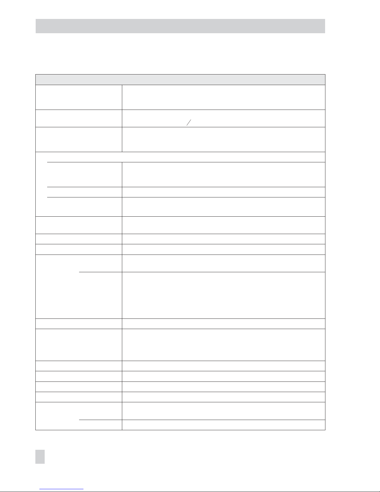
3.3 Technical data
10 EB 8387-5 EN
Design and principle of operation
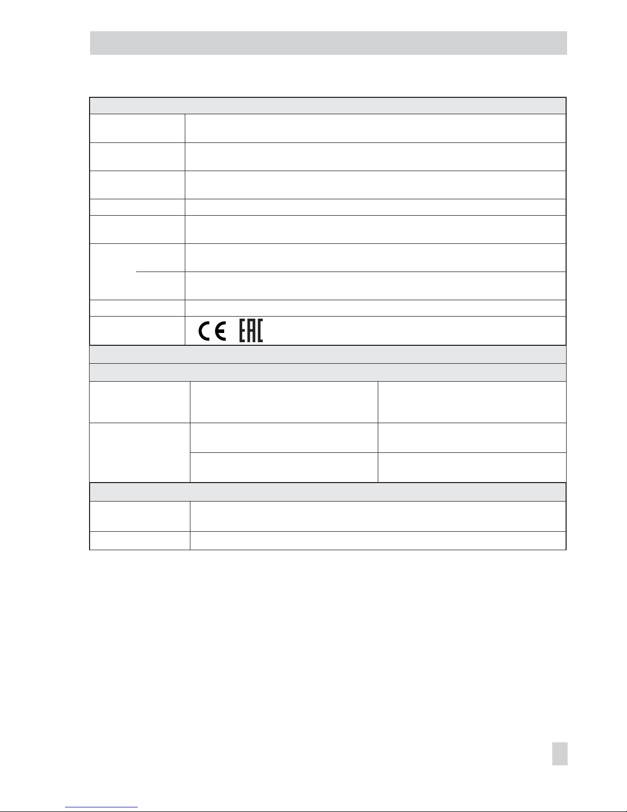
Type 3731-5 Ex d Positioner (technical data in test certificates additionally apply for explosion-protected devices)
Rated travel Adjustable Direct attachment to Type 3277: 3.6 to 30 mm
Attachment acc. to IEC 60534-6 (NAMUR): 3.6 to 200 mm
Attachment to rotary actuators (VDI/VDE 3845): 24° to 100°
Travel range Adjustable Adjustable within the initialized travel/angle of rotation;
travel can be restricted to
1
5
at the maximum
Bus connection Fieldbus interface acc. to IEC 61158-2 bus-powered
Physical Layer Class: 113 (without ex. protection) und 111 (with ex. protection)
Field device acc. to FM 3610 Entity and FISCO
Communication
Fieldbus Data transmission as per F
OUNDATION™ fieldbus specification,
Communication Profile Class: 31 PS, 32 L;
Interoperability tested according to Interoperability Test System (ITS) Revision 4.6
Execution time
AO FB: 20 ms DI FB: 40 ms PID: 60 ms
Local communication SAMSON SSP interface and serial interface adapter
Software requirements (SSP): TROVIS-VIEW with database module 3731-5
Permissible operating
voltage
9 to 32 V DC · Powered over bus line
The limits in the test certificate additionally apply.
Max. operating current 15 mA
Additional current in case of fault 0 mA
Supply air Pressure Type 3731-521, Type 3731-527: 1.4 to 7 bar (20 to 105 psi),
Type 3731-523: 1.4 to 6 bar (20 to 90 psi)
Air quality Compliance with ISO 8573-1: 2004
Max. particle size and density: Class 4
Oil content: Class 3
Moisture and water: Class 3
Pressure dew point: At least 10 K beneath the lowest ambient temperature to be
expected
Signal pressure (output) 0 bar up to supply pressure
Characteristic Linear/equal percentage/reverse equal percentage
User-defined (over operating software and communication)
Butterfly valve/Rotary plug valve/Segmented ball valve: linear/equal percentage
Deviation from terminal-based conformity≤1 %
Hysteresis
≤
0.3 %
Sensitivity
≤
0.1 %
Direction of action Reversible
Air consumption Independent from supply pressure 110 l
n
/h
Air output
capacity
to fill actuator
with air
At∆p = 6 bar: 8.5 mn³/h · At∆p = 1.4 bar: 30 mn³/h · K
Vmax(20° C)
= 0.09
to vent actuator
At∆p = 6 bar: 14.0 m
n
³/h · At∆p = 1.4 bar: 4.5 mn³/h · K
Vmax(20° C)
= 0.15
Page 11
EB 8387-5 EN 11
Design and principle of operation
Type 3731-5 Ex d Positioner (technical data in test certificates additionally apply for explosion-protected devices)
Influences Temperature:≤0.15/10 K · Supply air: None
Vibration:≤0.25 % up to 2000 Hz and 4 g acc. to IEC 770
EMC Complying with requirements of EN 61000-6-2, EN 61000-6-3, EN 61326-1 and NAMUR
Recommendation NE 21
Electrical connections Two threaded connections with ½ NPT thread, optionally with M20 x 1.5
Screw terminals for 2.5 mm² wire cross-section
Degree of protection IP 66/NEMA 4 X
Perm. storage
temperature
–60 to 80 °C
Materials Housing Die-cast aluminum EN AC-AlSi10Mg(Fe) (EN AC-44300) acc. to DIN EN 1706
chromated and powder paint coated
External
parts
Stainless steel 1.4571 and 1.4301
Weight Approx. 2.5 kg
Compliance
·
·
Additional equipment
Option: Binary input, galvanically isolated
Connection Terminals A-B
Voltage input 0 to 30 V DC,
reverse polarity protection
Terminals B-C
for external floating contact
Input Current consumption: 3.5 mA at 24 V
Static destruction limit: 40 V
R < 100Ω; contact loadability: 100 mA
Static destruction limit: 20 V/5.8 mA
Signal “1“ at Ue > 5 V
Signal “0“ at Ue < 3 V
Option: Forced venting, galvanically isolated
Input 0 to 40 V DC/0 to 28 V AC, reverse polarity protection 45 V DC/32 V AC,
input resistance≥7 k
Ω
Signal Fail-safe position at an input voltage≤3 V · Normal operation at an input voltage > 5.5 V
Page 12
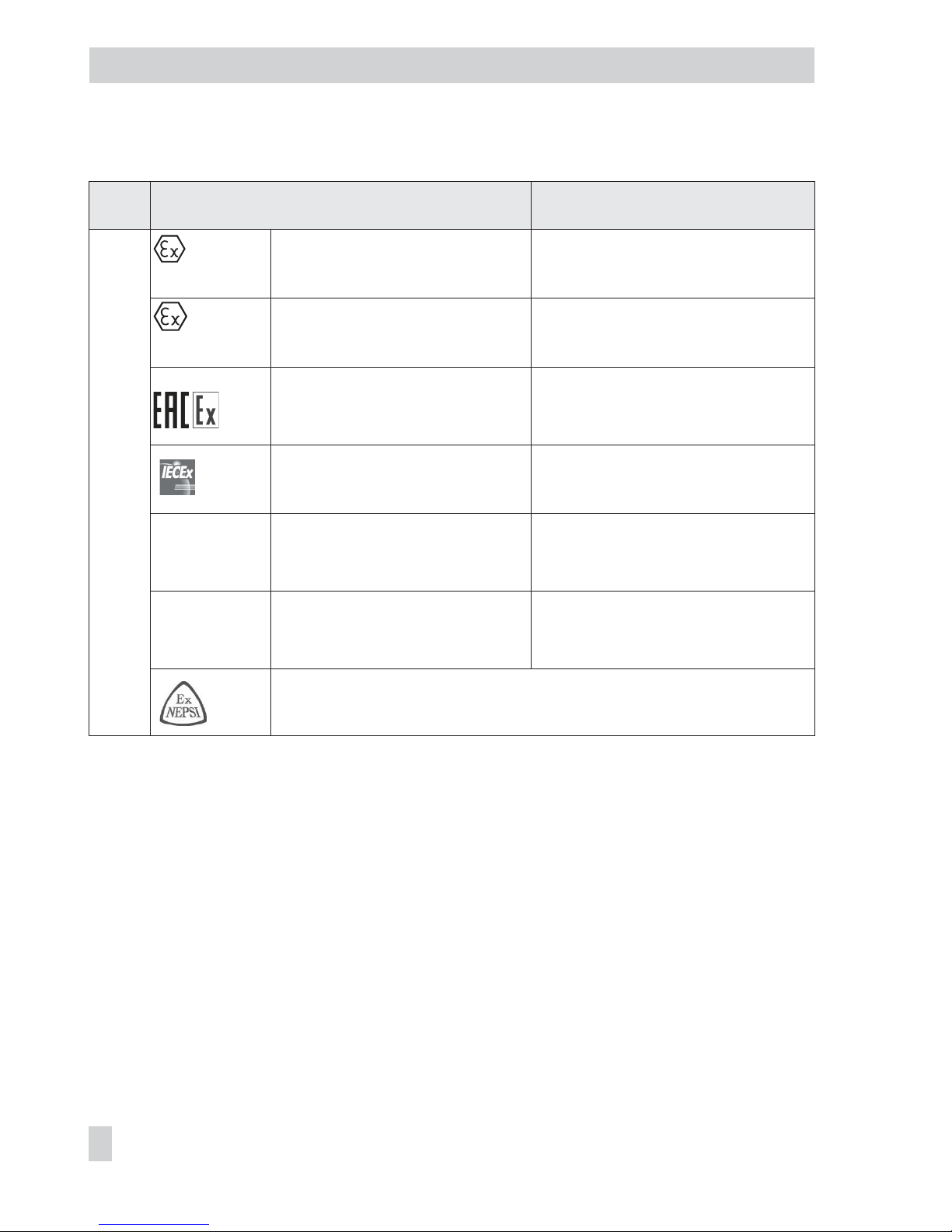
Summary of explosion protection certificates
12 EB 8387-5 EN
Design and principle of operation
Type
3731- Certificate Type of protection/comments
521
EC-type
examination
certificate
Number
Date
PTB11 ATEX 1014 X
2012-07-26
II 2G Ex d IIC T6,T5,T4 Gb;
II 2G Ex de IIC T6,T5,T4 Gb;
II 2D Ex tb IIIC T80°C DB IP66
EC-type
examination
certificate
Number
Date
PTB05 ATEX 1058
2006-07-21
II 2G Exd IIC T6 Gb;
II 2G Exde IIC T6 Gb;
II 2D Ex tb IIIC IP65 T80°C
Number
Date
Valid until
RU C-DE-GB08.B.00697
2014-12-15
2019-12-14
1Exd IIC T6/T5/T4 Gb X;
1Exd e IIC T6/T5/T4 Gb X;
Ex tb IIIC T80°C Db X
Number
Date
IECEx PTB11.0084X
2011-09-14
Exd IIC T6, T5, T4 Gb;
Exd e IIC T6, T5, T4 Gb;
Ex tb IIIC T80°C Db IP66
INMETRO
Number
Date
Valid until
IEx 13.0193X
2013-10-15
2016-10-14
Exd IIC T* Gb;
Exde IIC T* Gb;
* See ambient temperature
KCS
Number
Date
Valid until
13-KB4BO-0036
2013-01-31
2016-01-31
Exd IIC T6/T5/T4
On request
Page 13
4 Attachment to the control
valve – Mounting parts and
accessories
WARNING!
Attach the positioner, keeping the following
sequence:
1. Mount the positioner on the control valve
2. Connect the supply air
3. Connect the electrical power
4. Perform the start-up settings
The positioner is suitable for the following
types of attachment:
4
Direct attachment to SAMSON
Type 3277 Actuator
4
Attachment to actuators according to
IEC 60534-6 (NAMUR)
4
Attachment to Type 3510 Micro-flow
Valve
4
Attachment to rotary actuators
NOTICE
Attach the positioner to the control valve,
observing the following instructions to avoid
damaging the positioner.
–
Use only the mounting parts/accessories
listed in the Tables 1 to 5 (pages 28 and
30) to mount the positioner. Observe the
type of attachment.
–
The positioner is fitted with pneumatic
connections with ¼ NPT threads. If you
need G ¼ threads, attach the connecting
plate (6) listed in the accessories.
–
Observe the assignment between lever
and pin position (see travel tables on
page
14).
–
Fit a signal pressure restriction (Table 5
on page 30) for actuators with di
-
aphragm areas less than 240 cm².
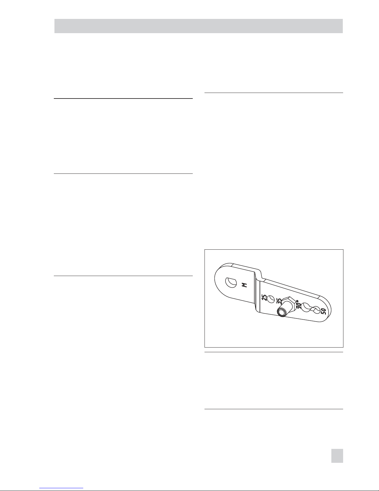
Lever and pin position
The positioner is adapted to the actuator
and to the rated travel by the lever on the
back of the positioner and the pin inserted
into the lever.
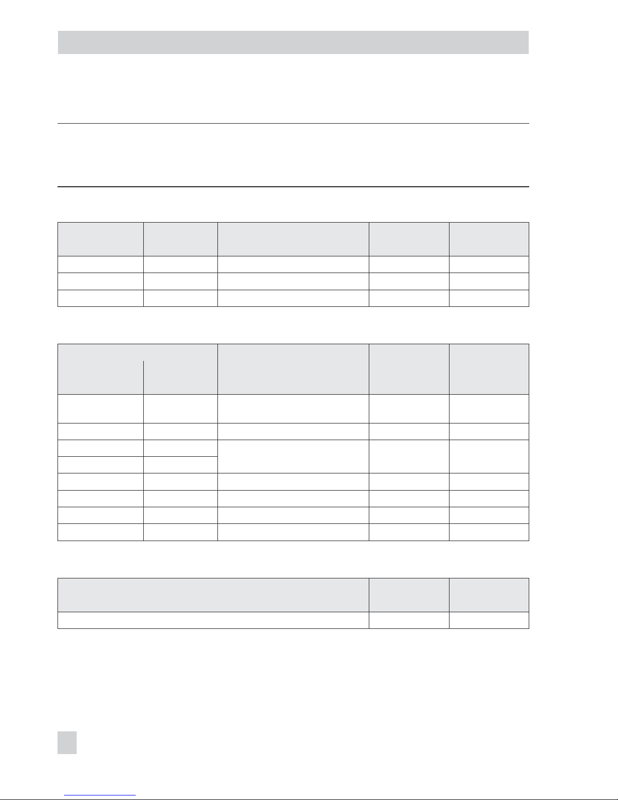
The travel tables on page 14 show the maxi
mum adjustment range at the positioner. The
travel that can be implemented at the valve
is restricted by the pin position used and ad
ditionally by the selected fail-safe position
and the required compression of the actua
-
tor springs.
The positioner is standard equipped with the
lever M (pin position 35).
Note: If the standard mounted lever M is re
placed, the newly mounted lever must be
moved once all the way as far as it will go
in both directions to adapt it to the internal
measuring lever.
EB 8387-5 EN 13
Attachment to the control valve – Mounting parts and accessories
Fig. 3 · Lever M with pin position 35 (delivered state)
Page 14
14 EB 8387-5 EN
Attachment to the control valve – Mounting parts and accessories
Travel tables
Note: The lever M is included in the scope of delivery.
Levers S, L, XL for attachment according to IEC 60534-6 (NAMUR) are available as accesso
-
ries (see Table 3 on page 30).
Direct attachment to Type 3277-5 and Type 3277 Actuators
Actuator size Rated travel Adjustment range at positioner
Required
lever
Assigned
pin position
[cm²] [mm] Min. Travel Max.
120 7.5 5.0 to 25.0 M 25
120/175/240/350 15 7.0 to 35.0 M 35
300/355/700 30 10.0 to 50.0 M 50
Attachment according to IEC 60534-6 (NAMUR)
SAMSON valves/Type 3271 Actuator Other valves/actuators
Required
lever
Assigned
pin position
Actuator size Rated travel
[cm²] [mm] Min. Travel Max.
60 and 120 with
Type 3510 Valve
7.5
3.6
to 18.0 S 17
120 7.5 5.0 to 25.0 M 25
120/175/240/350 15
7.0 to 35.0 M 35
700/750 7.5
355/700/750 15 and 30 10.0 to 50.0 M 50
1000/1400/2800 30 14.0 to 70.0 L 70
1000/1400/2800 60 20.0 to 100.0 L 100
1400/2800 120 40.0 to 200.0 XL 200
Attachment to rotary actuators according to VDI/VDE 3845
Rotary actuators
Required
lever
Assigned
pin position
Min. Opening angle Max.
24 to 100° M 90°
Page 15

4.1 Direct attachment
4.1.1 Type 3277-5 Actuator
Refer to Table 1 on page 28 for required
mounting parts and accessories.
Actuator with 120 cm²
NOTICE
If a solenoid valve or similar is additionally
mounted to the control valve, observe the
following instructions which differ from the
instructions otherwise described:
–
The switchover plate (9) is omitted.
–
The signal pressure must be routed from
the signal pressure output over the con
necting plate (order no. 1400-6820) to
the actuator.
– Fit the screw-in restriction (accessories,
order no. 1400-6964/item no.
0390-1424) into the signal pressure output.
–
Do not remove the screw plug (4) at the
back of the positioner.
Depending on the type of positioner attach
ment, the signal pressure is routed either left
or right of the yoke through a bore to the
actuator diaphragm.
1.
Refer to Fig. 4 to select the symbol to
match the required fail-safe position
and how the positioner is attached:
Fail-safe position:
“Actuator stem extends“ = Air-to-open
“Actuator stem retracts“ = Air-to-close
Positioner attachment: Left or right with
view looking onto the switchover plate
2. Align the marking of the switchover
plate (9) to the corresponding symbol
and mount the plate on the actuator
yoke.
3. If applicable, mount pressure gauge
bracket (7) with pressure gauges or, in
case G ¼ threaded connections are re
-
quired, the connecting plate (6), mak
ing sure both seal rings (6.1) are
seated properly.
4. Remove screw plug (4) on the back of
the positioner and seal the signal pres
-
sure output "Output 38" on the con
necting plate (6) or on the pressure
gauge bracket (7) with the stopper (5)
included in the accessories.
5. Place follower clamp (3) on the actuator stem, align and screw tight so that
the mounting screw is located in the
groove of the actuator stem.
6. Press brass restriction (accessories,
order no. 1400-6964/item no.
0390-1423) into the seal of the signal
pressure input at the actuator yoke.
7. Mount cover plate (10) with the narrow
side of the cut-out opening (Fig. 4, left)
pointing towards the signal pressure
connection. Make sure that the bonded
gasket (14) points towards the actuator
yoke.
8. 15 mm travel: Keep the follower pin
(2) at lever M (1) on the back of the
positioner in the pin position 35 (deliv
-
ered state).
7.5 mm travel: Remove the follower pin
(2) from the pin position 35, reposition
it in the hole for pin position 25 and
screw tight.
EB 8387-5 EN 15
Attachment to the control valve – Mounting parts and accessories
Page 16

9. Insert formed seal (15) into the groove
of the positioner housing, pressing the
four retaining rings over the housing
screws and both fittings into the hous
-
ing recesses.
10. Thread the bias spring (17) through the
crosspiece underneath the lever (1) and
push into the hole in the housing. Push
the lever (1) until it engages into place.
Place positioner on the cover plate (10)
and fasten it using the three fixing
screws.
Check to make sure that the follower
pin (2) rest on top of the follower clamp
(3). The lever (1) must rest on the follower clamp with spring force.
Make sure that the seal ring (10.1) is
inserted in the borehole of the cover
plate.
11. Mount cover (11) on the other side.
Make sure that the vent plug (11.1)
points downwards when the control
valve is installed to allow any con
-
densed water that collects to drain off.
16 EB 8387-5 EN
Attachment to the control valve – Mounting parts and accessories
Page 17
EB 8387-5 EN 17
Attachment to the control valve – Mounting parts and accessories
9
11
Supply 9
Output 38
5
6
4
17
7
6
10
10.1
3
2
1
15
6.1
1.1
1.2
14
8
11.1
A
A-A
A
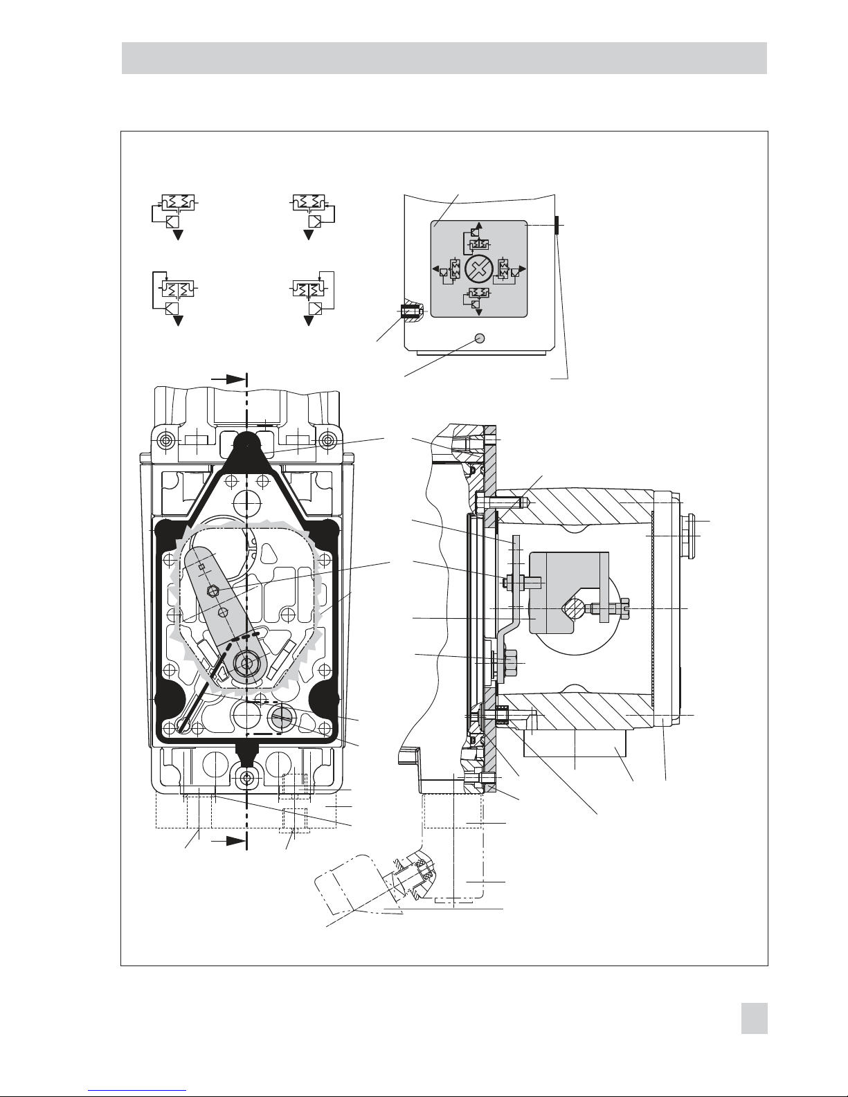
Fig. 4 · Direct attachment for Type 3277-5 Actuator with 120 cm²
Switchover plate (9)
Marking
1 Lever
1.1 Nut
1.2 Disk spring
2 Follower pin
3 Follower clamp
4 Screw plug
5 Stopper
6 Connecting plate for G ¼
6.1 Seal rings
7 Pressure gauge bracket
8 Press. gauge mounting kit
9 Switchover plate
for actuator
10 Cover plate
10.1 Seal ring
11 Cover
11.1 Vent plug
14 Gasket
15 Formed seal
17 Bias spring (only with
direct attachment)
Signal pressure input
for right attachment
Symbols
Actuator stem
extends
Left attachment Right attachment
Actuator stem
retracts
Signal pressure
input for left
attachment
Signal pressure input
with brass restriction
Cut-out of
cover plate
Page 18

4.1.2 Type 3277 Actuator
Refer to Table 2 on page 28 for the required
mounting parts and accessories.
Actuators with 175 to 750 cm²
Mount the positioner on the yoke as shown
in Fig. 5. The signal pressure is routed to the
actuator over the connection block (12), for
actuators with fail-safe action "Actuator
stem extends" internally through a bore in
the valve yoke and for "Actuator stem re
-
tracts" through external piping.
1. Place follower clamp (3) on the actua
tor stem, align and screw tight so that
the mounting screw is located in the
groove of the actuator stem.
2. Mount cover plate (10) with the narrow
side of the cut-out opening (Fig. 5, left)
pointing towards the signal pressure
connection. Make sure that the bonded
gasket (14) points towards the actuator
yoke.
3. Actuators with 355, 700 and 750 cm²:
Remove the follower pin (2) at lever M
(1) on the back of the positioner from
pin position 35, reposition it in the hole
for pin position 50 and screw tight.
Actuators with 175 to 350 cm² with
15 mm travel: The follower pin (2) re
mains in pin position 35 (delivered
state).
4. Insert formed seal (15) into the groove
of the positioner housing, pressing the
four retaining rings over the housing
screws and both fittings into the hous
-
ing recesses.
5. Thread the bias spring (17) through the
crosspiece underneath the lever (1) and
push into the hole in the housing. Push
the lever (1) until it engages into place.
Place positioner on the cover plate (10)
and fasten it using three fixing screws.
Check whether the follower pin (2) rests
on top of the follower clamp (3).
The lever (1) must rest on the follower
clamp with spring force.
6. Make sure that the tip of the gasket
(16) projecting from the side of the
connection block (12) is positioned
above the actuator symbol that corre
sponds with the actuator with fail-safe
action "Actuator stem extends" or "Ac
tuator stem retracts." If necessary, remove the three fixing screws and the
cover plate. Then reposition the gasket
(16) turned by 180°. The previous version of the connection block (Fig. 5,
bottom) requires the switch plate (13) to
be turned such that the corresponding
actuator symbol points to the marking.
7. Actuators with 175 cm²: Unscrew the
filter from the signal pressure input and
first screw the screw restriction (acces
sories order no. 1400-6964/item no.
0390-1424) into the input and then the
filter.
8. Place the connection block (12) with the
associated seal rings against the
positioner and the actuator yoke. Screw
it tight using the fixing screw (12.1).
For actuators with fail-safe action "Ac
-
tuator stem retracts", additionally re
move the stopper (12.2) and attach the
external signal pressure line.
18 EB 8387-5 EN
Attachment to the control valve – Mounting parts and accessories
Page 19
EB 8387-5 EN 19
Attachment to the control valve – Mounting parts and accessories
2
17
10 1415
1
2
3
11
SUPPLY
13
B
1.1
1.2
12
12.1
12
12.2
12.11216
1616
12.2
SUPPLY
Ansicht B
Ansicht A
Ansicht C
SUPPLYG
G 3/8
11.1
A
C
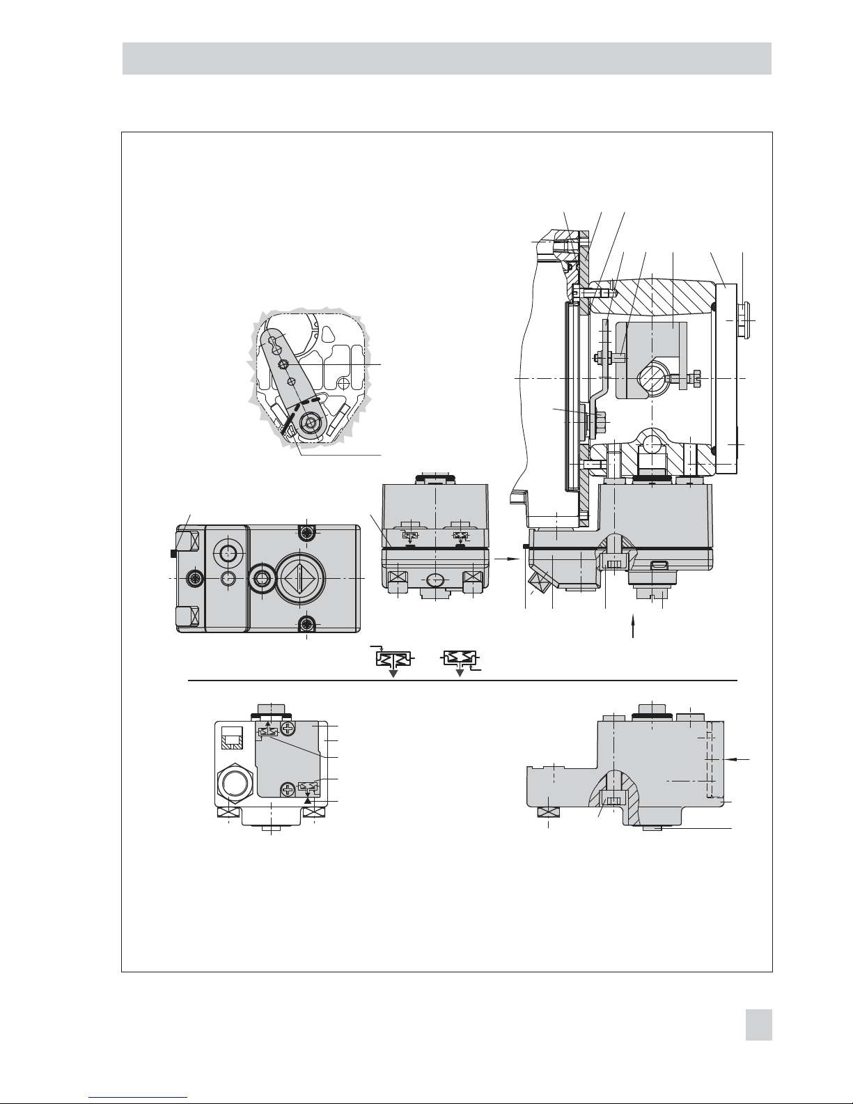
Fig. 5 · Direct attachment – Signal pressure connection for Type 3277 Actuator with 175 to 750 cm
2
View A
1 Lever
1.1 Nut
1.2 Disk spring
2 Follower pin
3 Follower clamp
10 Cover plate G ¼
11 Cover
11.1 Vent plug
Connection block (old)
with switch plate (13)
12 Connection block
12.1 Screw
12.2 Stopper or connection for
external piping
13 Switch plate
14 Gasket
15 Formed seal
16 Gasket
17 Bias spring
(only for direct attachment)
Cut-out of
cover plate (10)
Stem retracts
Stem extends
Marking
View A
View C
View B
Actuator stem
retracts extends
Page 20

9. Mount cover (11) on the other side.
Make sure that the vent plug (11.1)
points to the back when the control
valve is installed to allow any con
-
densed water that collects to drain off.
4.2 Attachment according to
IEC 60534-6 (NAMUR)
Refer to Table 3 on page 30 for the required
mounting parts and accessories.
The positioner is attached to the control
valve using a NAMUR bracket (10).
1. Actuator with 175 cm²:
Unscrew the filter from the signal pressure input and first screw the screw restriction (accessories order no.
1400-6964/item no. 0390-1424) into
the input and then the filter.
2. Actuator sizes 120 to 750 cm²:
Screw the two bolts (14) to the bracket
(9.1) of the stem connector (9), place
the follower plate (3) on top and tighten
it using the screws (14.1).
Actuator size 2800 cm² and 1400 cm²
(120 mm travel):
–
For a travel of 60 mm or smaller,
screw the longer follower plate (3.1)
directly to the stem connector (9).
–
For a travel exceeding 60 mm,
mount the bracket (16) first and then
the follower plate (3) to the bracket
together with the bolts (14) and
screws (14.1).
3. Mount NAMUR bracket (10) to the con
-
trol valve as follows:
–
For attachment to the NAMUR rib,
use an M8 screw (11), washer and
toothed lock washer directly in the
yoke bore.
–
For attachment to valves with
rod-type yokes, use two U-bolts (15)
around the yoke. Align the NAMUR
bracket (10) in such a way that the
slot of the follower plate (3/3.1) is
centrally aligned with the NAMUR
bracket at mid valve travel.
4. If applicable, mount pressure gauge
bracket (7) with pressure gauges or, in
case G ¼ threaded connections are re
quired, the connecting plate (6), making sure both seal rings (6.1) are
seated properly.
5. Screw a screw restriction (accessories
order no. 1400-6964/item no.
0390-1424) into the signal pressure
output for actuators with diaphragm areas smaller than 240 cm².
6. Select required lever (1) size M, L or XL
and pin position according to the actu
ator size and valve travels listed in the
table on page 14.
Lever M with pin position 25 or 50:
6.1 Remove follower pin (2) from pin posi
tion 35 and screw it into the required
hole.
Lever L or XL:
6.1 Unscrew the standard lever M from the
shaft of the positioner.
6.2 Screw the long follower pin (2) in
cluded in the mounting kit in the pin
position of the required lever (1) as
-
signed in the table.
20 EB 8387-5 EN
Attachment to the control valve – Mounting parts and accessories
Page 21
EB 8387-5 EN 21
Attachment to the control valve – Mounting parts and accessories
10
11
1
1
14.1
3
3.1
16
15
14
1
1.2
1.1
2
9.1
9
6
7
8
6.1
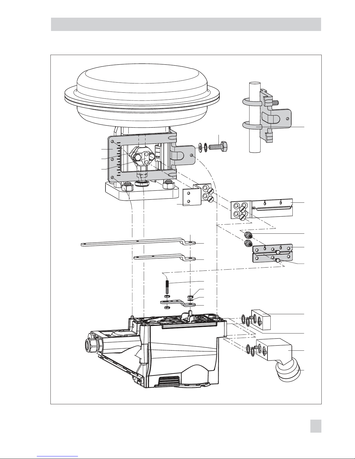
Fig. 6 · Attachment according to IEC 60534-6 (NAMUR)
1 Lever
1.1 Nut
1.2 Disk spring
3 Follower plate
3.1 Follower plate
6 Connecting plate
(only for G ¼)
6.1 Seal rings
7 Pressure gauge bracket
8 Pressure gauge
mounting kit
9 Stem connector
9.1 Bracket
10 NAMUR bracket
11 Screw
14 Bolt
14.1 Screw
15 U-bolt
16 Bracket
Additional bracket for
actuators with 2800 cm²
and travel≥60 mm
Fit screw-in restriction into output
(38) for actuators smaller than
240 cm²
Attachment to
NAMUR rib
Attachment to rod-type yoke
Rods with 20 to 35 mm Ø
Lever XL and L
Page 22

Place lever (1) on the positioner shaft
and screw tight using the disk spring
(1.2) and nut (1.1).
6.4 Move the lever once all the way as far
as it will go in both directions.
7. Place positioner on the NAMUR
bracket in such a manner that the fol
-
lower pin (2) rests in the slot of the fol
lower plate (3/3.1). Adjust the lever (1)
correspondingly. Screw the positioner
to the NAMUR bracket using three fix
ing screws.
4.3 Attachment to Type 3510
Micro-flow Valve
Refer to Table 3 on page 30 for the required
mounting parts and accessories.
The positioner is attached to the valve yoke
using a bracket.
1.
Mount the travel indication scale (accessories) onto the outer side of the
yoke using the hex screws (12.1), en
suring that the scale is aligned with the
stem connector.
2. Fasten the bracket (9.1) onto the stem
connector.
3. Fasten the two pins (9.2) to the bracket
(9.1) on the stem connector. Mount the
follower plate (3) and fasten it using the
screws (9.3).
4. Fasten the hex bar (11) onto the outer
side of yoke by screwing the M8 screws
(11.1) directly into the holes on the
yoke.
5. Fasten the bracket (10) to the hex bar
(11) using the hex screw (10.1),
washer and tooth lock washer.
6. If applicable, mount pressure gauge
bracket (7) with pressure gauges or, in
case G ¼ threaded connections are re
-
quired, the connecting plate (6), mak
ing sure both seal rings (6.1) are
seated properly.
7. Screw the restriction (accessories order
no. 1400-6964/item no. 0390-1424)
into the signal pressure output of the
positioner (or output of the pressure
gauge bracket or connecting plate).
8. Unscrew the standard installed lever M
(1) including follower pin (2) from the
positioner shaft.
9. Take lever S (1) and screw follower pin
(2) in the bore for pin position 17.
10. Place lever S on the positioner shaft
and screw tight using the disk spring
(1.2) and nut (1.1).
Move the lever once all the way as far
as it will go in both directions.
11. Place positioner on the bracket (10) in
such a manner that the follower pin
slides into the groove of the clamp (3).
Adjust the lever (1) correspondingly.
Screw the positioner to the bracket (10)
using both its screws.
22 EB 8387-5 EN
Attachment to the control valve – Mounting parts and accessories
Page 23
EB 8387-5 EN 23
Attachment to the control valve – Mounting parts and accessories
10.1
11.1
9
11
12.1
6
2
1
1.2
1.1
7
8
6.1
10
9.1
3
9.2
9.3
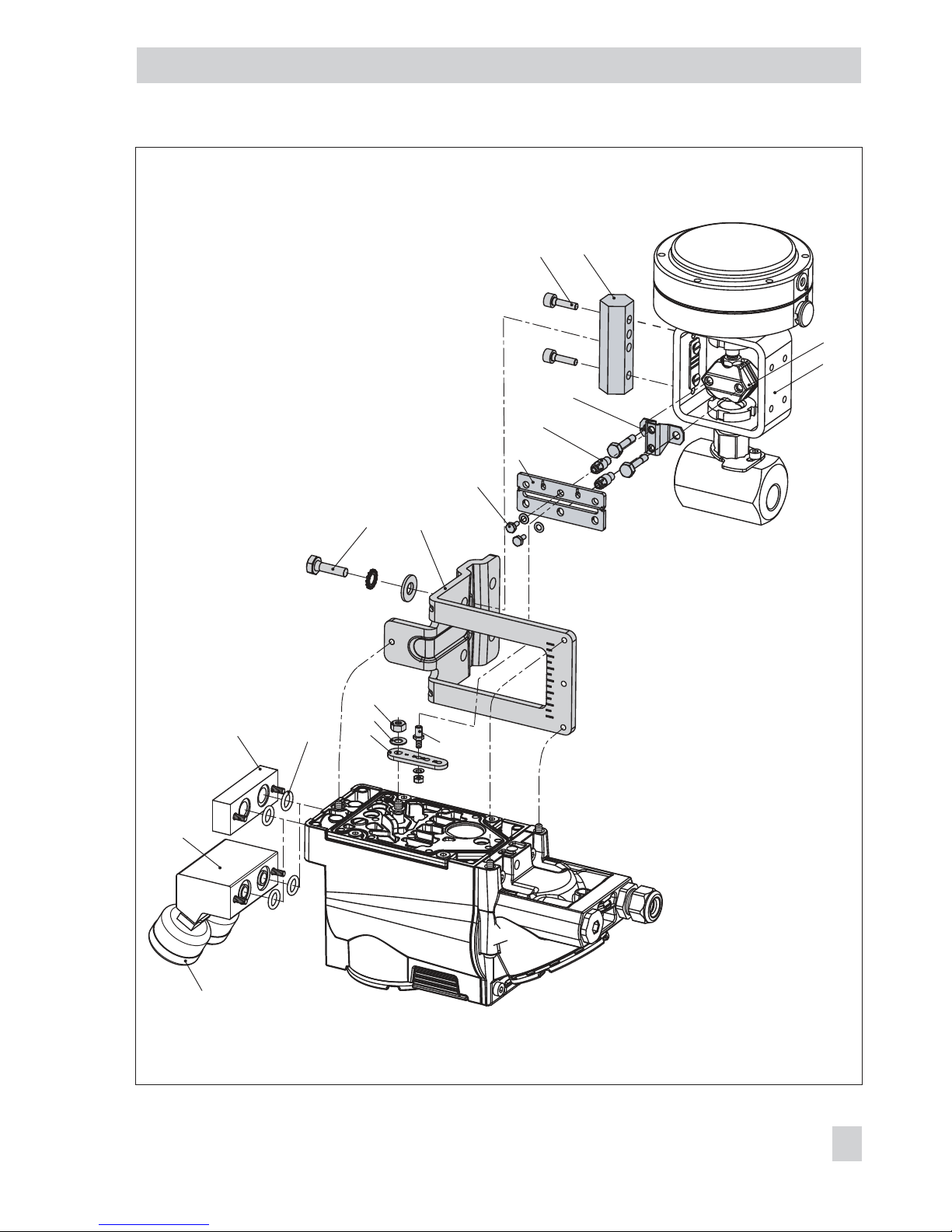
Fig. 7 · Attachment to Type 3510 Micro-flow Valve
Fit screw-in restriction into
output (38)
1 Lever
1.1 Nut
1.2 Disk spring
2 Follower pin
3 Follower plate
6 Connecting plate
6.1 Seal rings
7 Pressure gauge bracket
8 Pressure gauge mounting kit
9 Stem connector
9.1 Bracket
9.2 Pin
9.3 Screws
10 Bracket
10.1 Screw
11 Hex bar
11.1 Screws
12.1 Screws
Lever S
Page 24
4.4 Attachment to rotary
actuators
Refer to Table 4 on page 30 for the required
mounting parts and accessories.
Both mounting kits contain all the necessary
mounting parts. First select correct actuator
size. Prepare actuator, and mount required
adapter supplied by the actuator manufac
-
turer, if necessary.
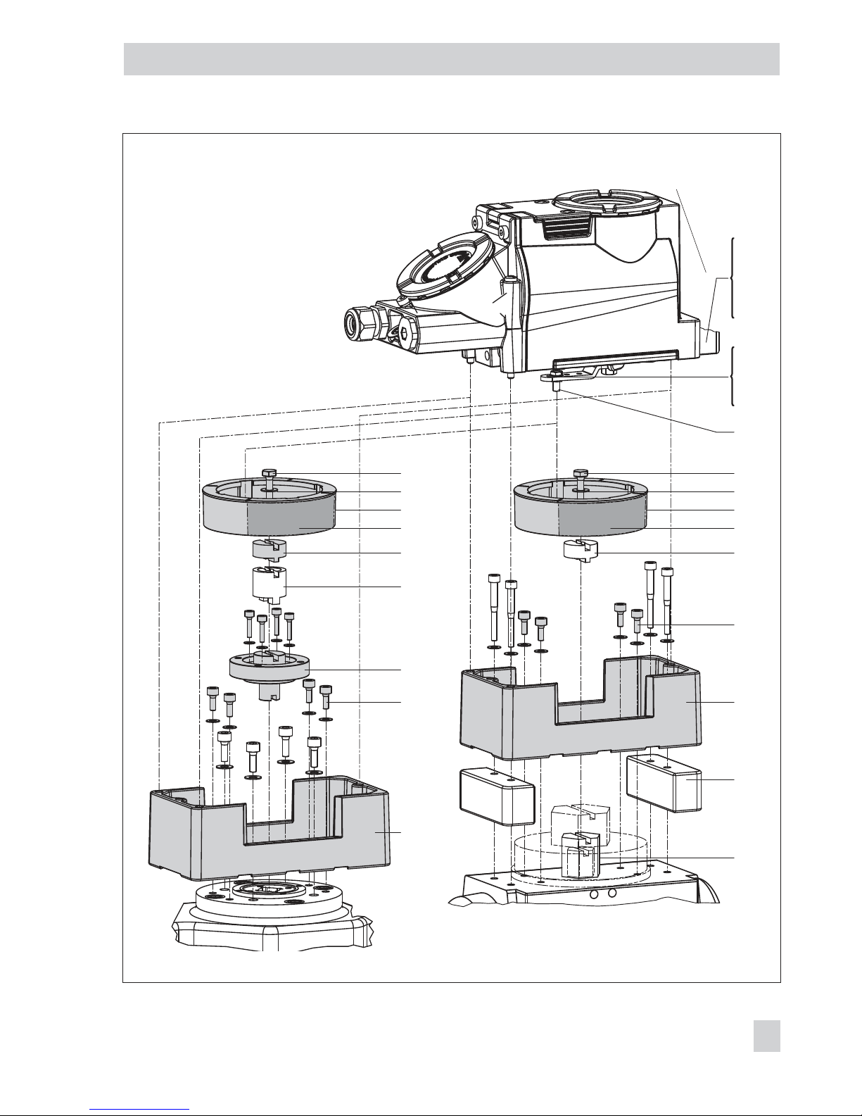
1. Mount the housing (10) onto the rotary
actuator. In case of VDI/VDE attach
ment, place spacers (11) underneath, if
necessary.
2. For SAMSON Type 3278 and VETEC
S160 Rotary Actuator, screw the
adapter (5) onto the free end of the
shaft or place adapter (5.1) onto the
shaft of the VETEC R Actuator.
Place adapter (3) onto Type 3278,
VETEC S160 and VETEC R Actuator. For
VDI/VDE version, this step depends on
the actuator size.
3. Stick adhesive label (4.3) onto the cou
pling wheel in such a manner that the
yellow part of the sticker is visible in the
window of the housing when the valve
is OPEN. Adhesive labels with explana
tory symbols are enclosed and can be
stuck on the housing, if required.
4. Screw tight coupling wheel (4) onto the
slotted actuator shaft or adapter (3) us
-
ing screw (4.1) and disk spring (4.2).
5. Undo the standard follower pin (2) on
the lever M (1) of the positioner. Attach
the follower pin (Ø 5) included in the
mounting kit to pin position 90°.
6. If applicable, mount pressure gauge
bracket (7) with pressure gauges or, in
case G ¼ threaded connections are re
-
quired, the connecting plate (6), mak
ing sure both seal rings (6.1) are
seated properly.
For double-acting, springless rotary ac
-
tuators, a reversing amplifier is re
quired to attach the positioner to the
actuator. Refer to section 4.5.
7. For actuators with a volume of less than
300 cm³, screw the screw restriction
(accessories order no.1400-6964/item
no. 0390-1424) into the signal pres
sure output of the positioner (or the output of the pressure gauge bracket or
connecting plate).
8. Place positioner on the housing (10)
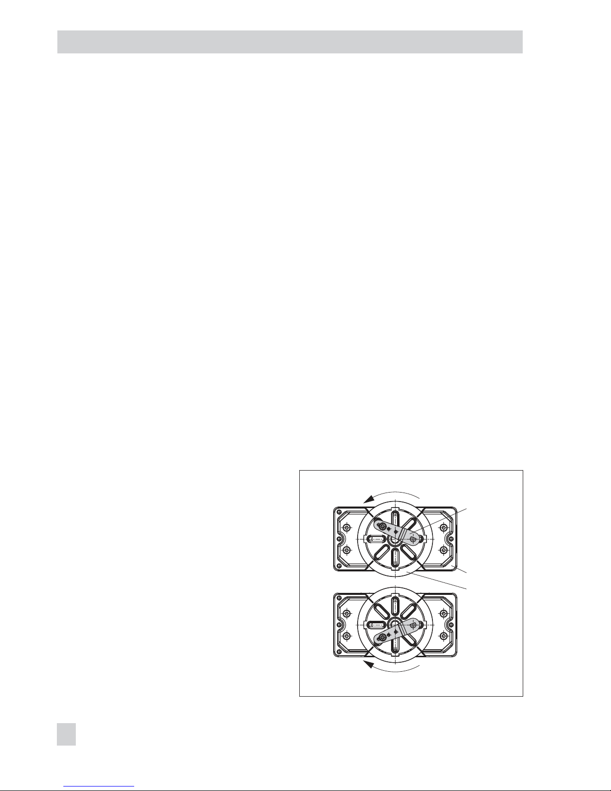
and screw it tight. Considering the actuator's direction of rotation, align lever
(1) so that it engages in the correct slot
of the coupling wheel with its follower
pin (Fig. 8).
24 EB 8387-5 EN
Attachment to the control valve – Mounting parts and accessories
1
10
4
Fig. 8 · Direction of rotation
Counterclockwise
Clockwise
Page 25
EB 8387-5 EN 25
Attachment to the control valve – Mounting parts and accessories
Counterclockwise
6
6.1
7
8
1
1.1
1.2
2
4.1
3
10.1
10
11
5
4.3
4
4.2
4.1
3
5.1
5
10.1
10
4.3
4
4.2
Fig. 9 · Attachment to rotary actuators
1 Lever
1.1 Nut
1.2 Disk spring
2 Follower pin
3 Adapter
4 Coupling
wheel
4.1 Screw
4.2 Disk spring
4.3 Adhesive label
5 Actuator shaft
or adapter
5.1 Adapter
6 Connecting plate (only for G ¼)
6.1 Seal rings
7 Pressure gauge bracket
8 Pressure gauge mounting kit
10 Adapter housing
10.1 Screws
11 Spacers
Fit screw-in restriction into signal pressure output
for actuators with < 300 cm³ volume
SAMSON Type 3278
VETEC S160, VETEC R
Attachment acc. to VDI/VDE 3845
(Sept. 2010) level 1, size AA1 to AA4
(see section 12.1)
Page 26

4.5 Reversing amplifier for
double-acting actuators
For the use with double-acting actuators, the
positioner must be fitted with a reversing
amplifier, e.g. the SAMSON Type 3710 Re
-
versing Amplifier (see Mounting and Oper
-
ating Instructions EB 8392).
If a different reversing amplifier (item no.
1079-1118 or 1079-1119) is used, follow
the mounting instructions described in sec
-
tion 4.5.1.
The following applies to all reversing am
-
plifiers:
The output signal pressure of the positioner
is supplied at the output A
1
of the reversing
amplifier. An opposing pressure, which
equals the required supply pressure when
added to the pressure at A
1
, is applied at
output A2.
The rule A1+ A2= Z applies.
A1: Output A1leading to the signal pressure
connection at the actuator which opens the
valve when the pressure increases
A
2
: Output A2leading to the signal pressure
connection at the actuator which closes the
valve when the pressure increases
4.5.1 Reversing amplifier
(1079-1118 or 1079-1119)
NOTICE
Do not unscrew sealing plug (1.5) out of the
reversing amplifier.
1. Thread the special nuts (1.3) from the
accessories of the reversing amplifier
into the boreholes of the positioner.
Remove the rubber seal (1.4).
2. Insert the gasket (1.2) into the recess of
the reversing amplifier and push both
the hollowed special screws (1.1) into
the connecting boreholes A1and Z.
3.
Position the reversing amplifier (1) and
screw tight using both the special
screws (1.1).
4. Use a screwdriver (8 mm wide) to
screw the enclosed filters (1.6) into the
connecting boreholes A
1
and Z.
NOTICE
On start up of double-acting actuators, the
following settings as described in section
must be made:
– Pressure limit (Code 16) = OFF
– Fail-safe position (Code 0) = AIR TO
OPEN (AtO)
Pressure gauge attachment
The mounting sequence shown in Fig. 10 re
mains unchanged. Screw a pressure gauge
bracket onto the connections A1and Z.
Pressure gauge
G ¼ 1400-7106
bracket: ¼ NPT 1400-7107
Pressure gauges for supply air Z and output
A
1
as listed in Tables 1 to 4.
26 EB 8387-5 EN
Attachment to the control valve – Mounting parts and accessories
Page 27

EB 8387-5 EN 27
Attachment to the control valve – Mounting parts and accessories
A
1
1.5 1.6
1.3 1.2 1.1 1 1.6
Z
A
2
1.4
A
1
A
2
Z
A
1
Output 38 Supply 9
Output 38 Supply 9
1.3 1.21.1
Fig. 10 · Mounting a reversing amplifier (1079-1118 or 1079-1119)
From the positioner
Control signals to
the actuator
1 Reversing amplifier
1.1
Special screws
1.2 Gasket
1.3 Special nuts
1.4 Rubber seal
1.5 Sealing plug
1.6 Filter
Page 28

4.6 Required mounting parts and accessories
28 EB 8387-5 EN
Attachment to the control valve – Mounting parts and accessories
Table 1 · Direct attachment to Type 3277-5 (Fig. 4)
Order no.
Mounting parts For actuators with 120 cm² effective diaphragm area 1400-7452
Version compatible with paint for actuators 120 cm² or smaller 1402-0940
Accessories for
the actuator
Switchover plate (old) for Actuator Type 3277-5xxxxxx.00 (old) 1400-6819
Switchover plate new for Actuator Type 3277-5xxxxxx.01 (new)
1)
1400-6822
Connecting plate new for Actuator Type 3277-5xxxxxx.01 (new)1), G
1
8
and
1
8
NPT 1400-6823
Connecting plate old for Actuator Type 3277-5xxxxxx.00 (old): G
1
8
1400-6820
Connecting plate old for Actuator Type 3277-5xxxxxx.00 (old):
1
8
NPT 1400-6821
Accessories for
the positioner
Connecting plate (6) G ¼ 1400-7461
Pressure gauge bracket (7)
G ¼ 1400-7458
¼ NPT 1400-7459
Pressure gauge mounting kit (8) up to max. 6 bar (output/supply)
St. st./Brass 1400-6950
St. st./St. st. 1400-6951
1)
Only new switchover and connecting plates can be used with new actuators (Index 01).
Old and new plates are not interchangeable.
Table 2 · Direct attachment to Type 3277 (Fig. 5) Order no.
Mounting
parts
Standard version for actuators with 175, 240, 350, 355, 700, 750 cm² 1400-7453
Version compatible with paint for actuators with 175, 240, 350, 355, 700, 750 cm² 1400-0941
Accessories
Required piping with screw
fitting
– for "Actuator stem retracts"
– with air purging of the top
diaphragm chamber
175 cm²
Steel
G
1
4
/ G
3
8
1402-0970
1
4
NPT /
3
8
NPT
1402-0976
Stainl. steel
G
1
4
/ G
3
8
1402-0971
1
4
NPT /
3
8
NPT
1402-0978
240 cm²
Steel
G
1
4
/ G
3
8
1400-6444
1
4
NPT /
3
8
NPT
1402-0911
Stainl. steel
G
1
4
/ G
3
8
1400-6445
1
4
NPT /
3
8
NPT
1402-0912
350 cm²
Steel
G
1
4
/ G
3
8
1400-6446
1
4
NPT /
3
8
NPT
1402-0913
Stainl. steel
G
1
4
/ G
3
8
1400-6447
1
4
NPT /
3
8
NPT
1402-0914
Page 29
EB 8387-5 EN 29
Attachment to the control valve – Mounting parts and accessories
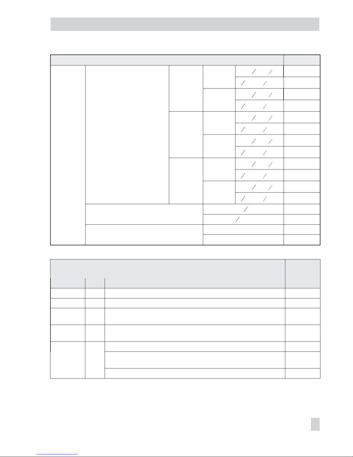
Table 2 · Direct attachment to Type 3277 (Fig. 5) Order no.
Accessories
Required piping with screw fitting
– for "Actuator stem retracts"
– with air purging of the top dia
-
phragm chamber
355 cm²
Steel
G
1
4
/ G
3
8
1402-0972
1
4
NPT /
3
8
NPT
1402-0979
Stainl. steel
G
1
4
/ G
3
8
1402-0973
1
4
NPT /
3
8
NPT
1402-0980
700 cm²
Steel
G
1
4
/ G
3
8
1400-6448
1
4
NPT /
3
8
NPT
1402-0915
Stainl. steel
G
1
4
/ G
3
8
1400-6449
1
4
NPT /
3
8
NPT
1402-0916
750 cm²
Steel
G
1
4
/ G
3
8
1402-0974
1
4
NPT /
3
8
NPT
1402-0981
Stainl. steel
G
1
4
/ G
3
8
1402-0975
1
4
NPT /
3
8
NPT
1402-0982
Connection block with seals and screw
G
1
4
1400-8819
1
4
NPT 1402-0901
Pressure gauge mounting kit (8) up to max. 6 bar
(output/supply)
Steel/brass 1400-6950
St. steel/St. steel 1400-6951
Table 3 · Attachment to NAMUR ribs or control valves with rod-type yokes
(20 to 35 mm rod diameter) according to IEC 60534-6 (Figs. 6 and 7)
Travel in mm Lever For actuators Order no.
7.5 S Type 3271-5 Actuator w. 60/120 cm² on Type 3510 Valve (Fig. 7) 1400-7457
5 to 50 M1)Actuators from other manufacturers and Type 3271with 120 to 700 cm² 1400-7454
14 to 100 L Actuators from other manufacturers and Type 3271, versions 1000 and
1400-60
1400-7455
40 to 200 XL
Actuators from other manufacturers and Type 3271, versions 1400-120 and
2800 cm² with 120 mm travel
1400-7456
30 or 60 L
Type 3271, versions 1400-120 and 2800 cm² (30 or 60 mm travel) 1400-7466
Mounting bracket for Emerson and Masoneilan linear actuators; a mounting
kit acc. to IEC 60534-6 is necessary depending on the travel (see above)
1400-6771
Valtek Type 25/50 1400-9554
Page 30
EB 8387-5 EN 30
Attachment to the control valve – Mounting parts and accessories
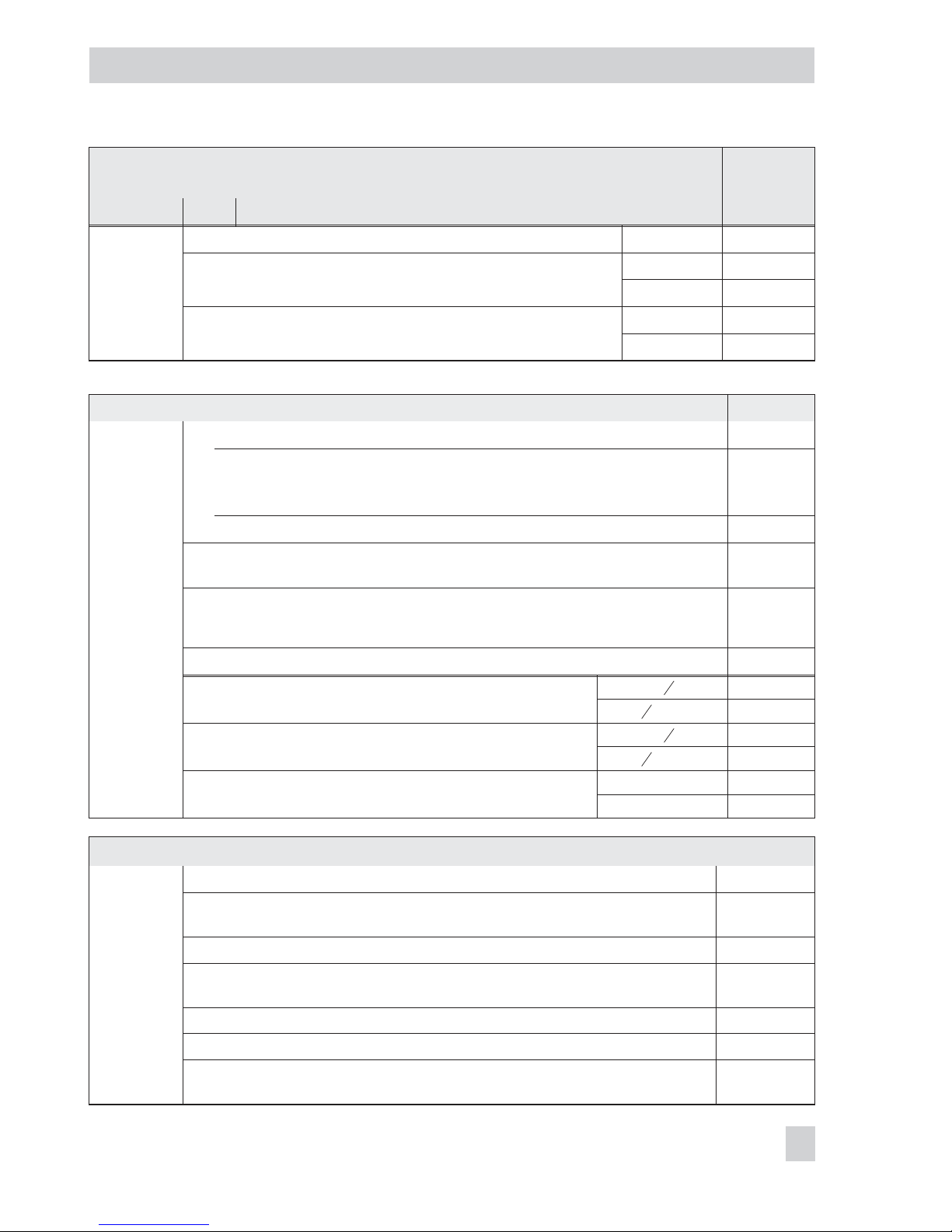
Table 3 · Attachment to NAMUR ribs or control valves with rod-type yokes
(20 to 35 mm rod diameter) according to IEC 60534-6 (Figs. 6 and 7)
Travel in mm Lever For actuators Order no.
Accessories
Connecting plate G ¼ 1400-7461
Pressure gauge bracket (7)
G ¼ 1400-7458
¼ NPT 1400-7459
Pressure gauge mounting kit (8) up to max. 6 bar (output/supply)
St. st./Brass 1400-6950
St. st./St. st. 1400-6951
1)
Lever M is attached to basic positioner (included in the scope of delivery)
Table 4 · Attachment to rotary actuators (Figs. 8 and 9)
Order no.
Mounting
parts
Attachment acc. to VDI/VDE 3845 (September 2010), see section 12.1 for details
Actuator surface corresponds to level 1
Size AA1 to AA4, heavy-duty version
Size AA5, heavy-duty version (e.g. Air Torque 10 000)
1400-9244
1400-9542
Bracket surface corresponds to level 2, heavy-duty version 1400-9526
Attachment for SAMSON Type 3278 with 160 cm² and for VETEC Type S160, R and
M, heavy-duty version
1400-9245
Attachment for SAMSON Type 3278 with 320 cm² and for VETEC Type S320,
heavy-duty version
1400-5891
and
1400-9526
Attachment to Camflex II
1400-9120
Accessories
Connecting plate (6)
G
1
4
1400-7461
1
4
NPT 1400-7462
Pressure gauge bracket (7)
G
1
4
1400-7458
1
4
NPT 1400-7459
Pressure gauge mounting kit up to max. 6 bar (output/supply)
St. steel/brass 1400-6950
St. steel/st. steel 1400-6951
Table 5 · General accessories
Order no.
Accessories
Reversing amplifier for double-acting actuators Type 3710
Signal pressure restrictions (screw restriction (item no. 0390-1424) and brass restric
-
tion (item no. 0390-1423))
1400-6964
Activation code for EXPERT+for Type 3731-5 Positioner 1400-9318
USB dongle for EXPERT+ (specify the number of activations)
Only can be used in combination with TROVIS-VIEW 6661-1065
1400-9555
TROVIS-VIEW with database module 3731-5 6661-1065
Serial interface adapter (SAMSON SSP interface – RS-232 port of computer)
1400-7700
Isolated USB interface adapter (SAMSON SSP interface – USB port on computer)
including TROVIS-VIEW CD-ROM
1400-9740
Page 31

5 Connections
WARNING!
Mount the positioner, keeping the following
sequence:
1. Mount the positioner on the control valve
2. Connect the supply air
3. Connect the electrical power
4. Perform the start-up settings
The connection of the electrical auxilary
power may cause the actuator stem to move,
depending on the operating mode.
Do not touch the actuator stem or obstruct it
to avoid risk of injury to hands or fingers.
5.1 Pneumatic connections
The maximum supply pressure at the input
is:
– 7 bar for Types 3731-521 and 3731-527
– 6 bar for Type 3731-523
DANGER!
Danger from the formation of an explosive
atmosphere!
The operator of the apparatus must ensure
that the working medium cannot form an ex
plosive atmosphere, i.e. only such gases
may be used which are free from substances
whose presence in the medium might lead to
the formation of an explosive atmosphere
(e.g. do not use flammable gases, oxygen or
oxygen-enriched gases).
Follow the instructions below to avoid dam
-
aging the positioner.
–
Do not exceed the maximum supply
pressure at the input.
–
The screw fittings with ¼ NPT thread can
be screwed directly into the positioner.
In case G ¼ threaded connections are
required, the fittings must be screwed
into the connecting plate (6) or pressure
gauge mounting block or connection
block available from the accessories.
Customary screw-in fittings for metal and
copper pipes or plastic hoses can be
used.
– The supply air must be dry and free from
oil and dust.
The maintenance instructions for upstream pressure reducing stations must be
observed.
Blow through all air pipes and hoses thoroughly prior to connecting them.
If the positioner is attached directly to the
Type 3277 Actuator, the connection of the
positioner's output pressure to the actuator is
fixed. For attachment according to
IEC 60534-6 (NAMUR), the signal pressure
can be routed to either the top or bottom di
-
aphragm chamber of the actuator, depend
-
ing on the actuator's fail-safe action "Actua
-
tor stem extends" or "Actuator stem re
tracts".
For rotary actuators, the manufacturer's
specifications for connection apply.
EB 8387-5 EN 31
Connections
Page 32

5.1.1 Signal pressure gauges
To monitor the supply air (Supply) and sig
nal pressure (Output), we recommend that
pressure gauges be attached (see accesso
-
ries in Tables 1 to 5).
5.1.2 Supply pressure
The required supply pressure (of supply air)
depends on the bench range and the actua
tor's operating direction (fail-safe action).
The bench range is registered on the name
-
plate either as spring range or signal pres
sure range depending on the actuator.
The direction of action is marked FA or FE,
or by a symbol.
Actuator stem extends FA (AIR TO OPEN)
Fail-safe position "Valve Closed"
(for globe and angle valves):
Required supply pressure = Upper bench
range value + 0.2 bar, minimum 1.4 bar.
Actuator stem retracts FE (AIR TO CLOSE)
Fail-safe position "Valve Open"
(for globe and angle valves):
For tight-closing valves, the maximum signal
pressure pst
max
is roughly estimated as fol
lows:
pst
max
= F +
d p
A
2
4
⋅ ⋅⋅π ∆
[bar]
d = Seat diameter [cm]
∆
p = Differential pressure across the valve
[bar]
A = Actuator diaphragm area [cm²]
F = Upper bench range of the actuator
[bar]
If there are no specifications, calculate as
follows:
Required supply pressure =
Upper bench range value + 1 bar
5.1.3 Signal pressure (output)
The signal pressure at the output (Out
-
put 38) of the positioner can be limited to
1.4, 2.4 or 3.7 bar in Code 16.
The limitation is not activated [OFF] by de
-
fault.
32 EB 8387-5 EN
Connections
Page 33
5.2 Electrical connections
EB 8387-5 EN 33
Connections
DANGER!
Risk of electric shock and/or the formation of an explosive atmosphere!
4
For electrical installation, you are required to observe the relevant
electrotechnical regulations and the accident prevention regulations that ap
-
ply in the country of use.
4
The following standard applies for assembly and installation in hazardous
areas: EN 60079-14 (VDE 0165 Part 1) Explosive atmospheres - Electrical
installations design, selection and erection.
Connection to conform with the type of protection Ex d (EN 60079-1):
The Type 3731-521 Positioner must be connected over the appropriate cable
glands or conduit systems which meet the requirements of EN 60079-1 (Electri
cal apparatus for explosive gas atmospheres - Part 1: Flameproof enclosures
"d") Clauses 13.1 and 13.2 and for which a special test certificate exists. Do
not use simple types of cable glands or blanking plugs.
Seal any cable entries that are not used using blanking plugs approved for this
purpose for installations according to the type of protection Ex db.
Install the connecting line rigidly and ensure it is protected adequately from being damaged. In case the temperature exceeds 70 °C at the cable entries, use
appropriate temperature-resistant connecting cables.
Integrate the positioner into the equipotential bonding system on site.
Connection to conform with the type of protection Ex e (EN 60079-7):
The cable and cable entries or blanking plugs must be certified according to the
type of protection Ex e (ATEX) and for which a special test certificate exists.
Devices used at ambient temperatures below –20 °C must have metal cable en
-
tries.
In cases where more than one cable core is connected to the same terminal,
make sure that each cable core is clamped adequately.
Two cables with varying cross-sections may only be connected to one terminal,
if this is not explicitly allowed in the documentation related to the electrical ap
-
paratus, when the two cables are secured with a common crimp sleeve before
-
hand.
Page 34
34 EB 8387-5 EN
Connections
Table 6 · Accessories Order no.
Cable gland M20 x 1.5; Ex e, black plastic 8808-0178
Blanking plugs; Ex de; stainless steel
(approvals: CENELEC, CSA, GOST, IECEx)
M20 x 1.5 8323-1203
½ NPT 8323-1204
Cable entry for unarmored cables; Ex e, Ex d, Ex tD A21
(approvals: CENELEC, IECEx)
M20 x 1.5 8808-0200
½ NPT 8808-2010
Connection to conform with the type of protection Ex i (EN 60079-11):
For connection to a certified, external instrinsically safe circuit, the terminal
compartment of the positioner may be opened within the hazardous area.
Only the terminal compartment is to be opened within the hazardous area to
connect it to a certified instrinsically safe circuit.
Positioners that are connected to non-intrinsically safe circuits are no longer
permitted to be used as instrinsically safe equipment.
The IP rating of the cable, cable entries and blanking plugs must be the same
as the positioner's degree of protection.
Page 35
Cable entry
The threaded connections for the terminal
compartment are designed with ½ NPT or
M20x1.5 threads.
The electrical connections are screw terminals for wire cross-sections of 0.2 to
2.5 mm² using a tightening torque of at least
0.5 Nm.
Note: The positioner is powered either over
the connection to the fieldbus segment or
over a DC voltage source (9 to 32 V) con
-
nected to the bus terminals in the positioner.
You are required to observe the relevant
regulations for use in hazardous areas!
EB 8387-5 EN 35
Connections
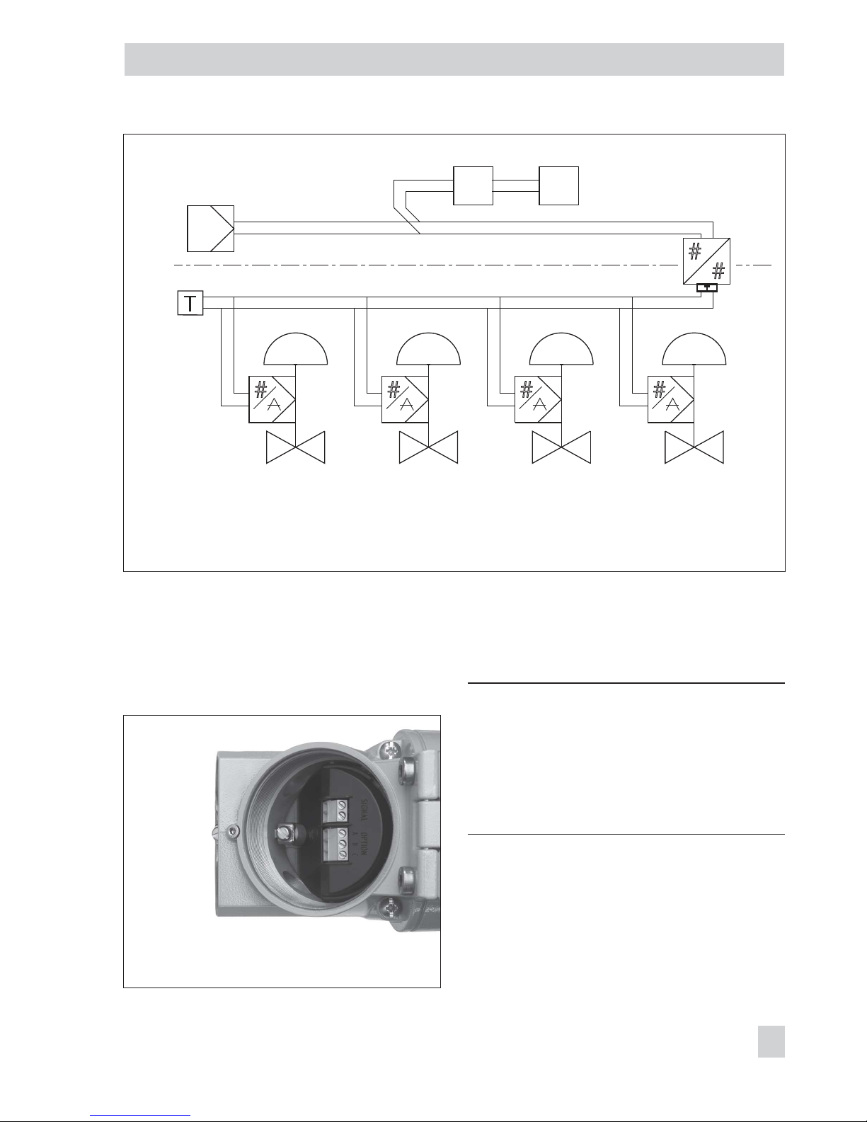
Power supply unit
Ex-fieldbus barrier/isolator
Hazardous area
Power conditioner
Control system
3731-52
3731-52
3731-52
3731-52
IEC 61158-2
IEC 61158-2
Bus termination
FOUNDATIONTM fieldbus
FOUNDATIONTM fieldbus
Fig. 11 · Connection according to FOUNDATIONTMfieldbus for hazardous areas
Fig. 12 · Location of the terminals
(lid unscrewed)
Page 36
Electrical auxiliary power supplied over the
bus line
4
Route the two-wire bus line to the screw
terminals marked “Signal”. Polarity does
not have to be observed.
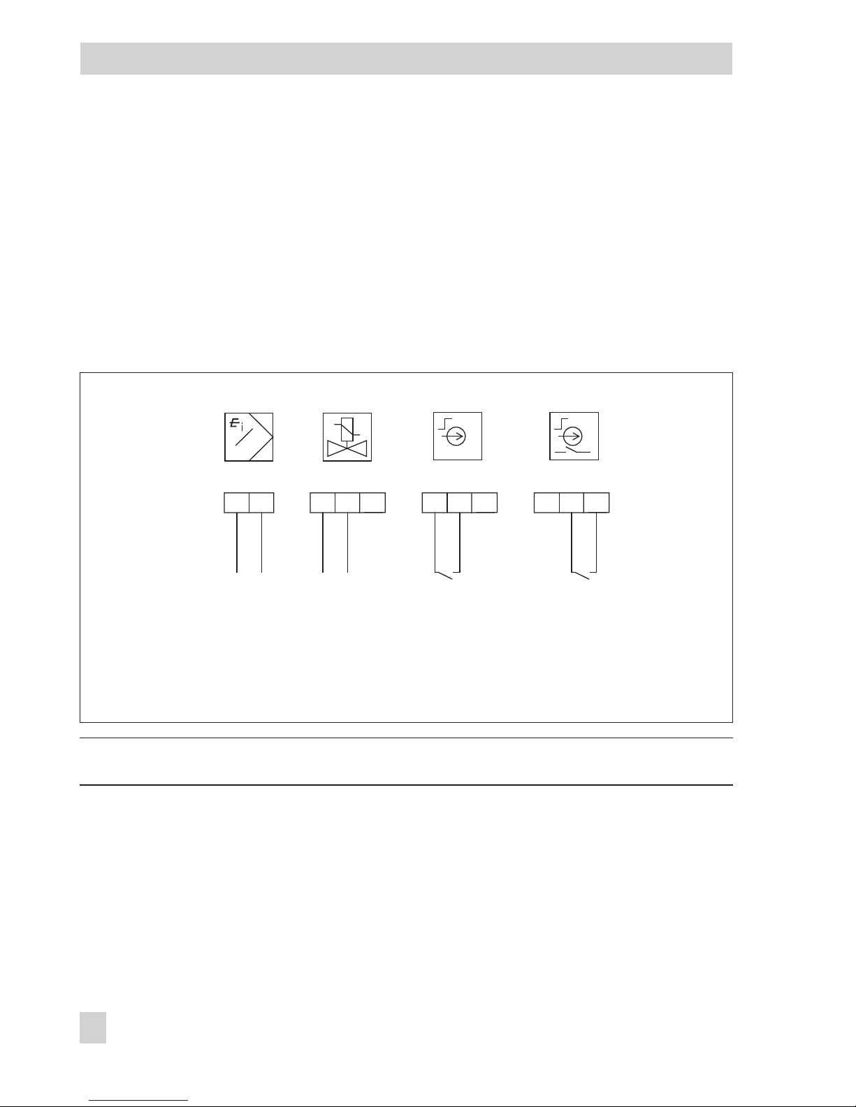
Refer to Fig. 13 or the nameplate for the
terminal assignment.
After connecting the electrical auxiliary
power,
tEStinG runs across the display of
the positioner.
Note: Just one binary input is available (either version 1 or version 2).
Version 1 of binary input (terminals A–B)
An active contact can be operated at version
1 of the binary input. The positioner signal
the switching state over the bus protocol.
Version 2 of binary input (terminals B–C)
A floating passive contact can be operated
at version 2 of the binary input. The
positioner receives the switching state over
the bus protocol.
36 EB 8387-5 EN
Connections
A B C
Option
+
_
A B C
Option
G
IEC 61158-2
Signal
A B C
Option
L/+
0...40 V DC
0...28 V AC
N/
_
+
_
u
Fig. 13 · Electrical connections
Forced venting
Version 1 Version 2
or
Binary input
Page 37

EB 8387-5 EN 37
Connections
NOTICE
The demanded degree of protection might
not be met because the terminal compart
ment is not sealed tightly. Only operate the
positioner with sealed cable entries and with
the lid screwed on properly.
NOTICE
Loss of explosion protection due to damaged
lid thread and/or connecting thread.
Do not open the flameproof enclosure when
the positioner is in the energized state. Ob
-
serve explosion protection regulations.
1. Unscrew lid.
2.
Guide the wires through the side cable
entry to the terminal compartment using
a cable gland or conduit system.
3. Connect wires to the terminals as
shown in the wiring diagram (Fig. 13).
4. Check O-ring for damage and replace
it with a new one, if necessary.
5. Screw on the lid as far as it will go.
Turn it back to first safety position
(notch).
6. Unscrew the cap screw to lock the lid.
5.2.1 Establishing communication
Communication between the controller or
automation system, or between a computer
or work station and the positioner(s) is im
-
plemented to conform with
EN 61158-2.
Note: Refer to the Configuration Manual
KH 8387-5 for more information.
Page 38

6 Operator controls and
readings
6.1 Rotary pushbutton
The rotary pushbutton ( ) is located under
-
neath the front protective cover.
The positioner is operated on site using the
rotary pushbutton:
Turn to select codes and values.
Press to confirm setting.
6.2 Serial interface
The serial interface connection is located un
-
derneath the display lid: Unscrew and re
move retaining screw and then unscrew display lid.
NOTICE
The explosion protection is ineffective as
soon as the display lid is opened!
To use the TROVIS-VIEW software, connect
the positioner over an adapter to the
RS-232 or USB port of the computer.
6.3 Readings on display
Icons appear on the display that are as
-
signed to parameters, codes and functions.
Operating modes
4
– Manual mode (MAN), see sec
tion 8.2.1
The positioner follows the manual set
point (Code 1) instead of the set point of
the Analog Ouput Block
4
– Automatic mode (AUTO), see
section
8.2.1
The positioner is in closed-loop operation
and follows the the set point of the Ana
-
log Output Block.
4
– SAFE, see section
8.2.2
The positioner vents the output. The valve
moves to the mechanical fail-safe position.
Bar elements
In manual and automatic operating
modes, the bars indicate the system devia
tion that depends on the sign (+/–) and the
value.
One bar element appears per 1 % system
deviation.
If the device has not yet been initialized, the
icon appears on the display and the lever
position in degrees in relation to the longitudinal axis is indicated. One bar element cor
responds to approximately a 5° angle of rotation.
If the fifth bar element blinks (reading
> 30°), the permissible angle of rotation has
been exceeded. Lever and pin position must
be checked.
Status messages
4
Maintenance alarm
4
Maintenance required/Maintenance
demanded
T
hese icons indicate that an error has occurred.
A classified status can be assigned to each
error. Classifications include “No message”,
“Maintenance required”, “Maintenance de
-
manded” or “Maintenance alarm“ (see sec
-
tion 8.3).
Configuration enabled
4
This indicates that the codes marked with
an asterisk (*) in the code list (section
11)
are enabled for configuration (see sec
-
tion 8.1).
38 EB 8387-5 EN
Operator controls and readings
S
Page 39
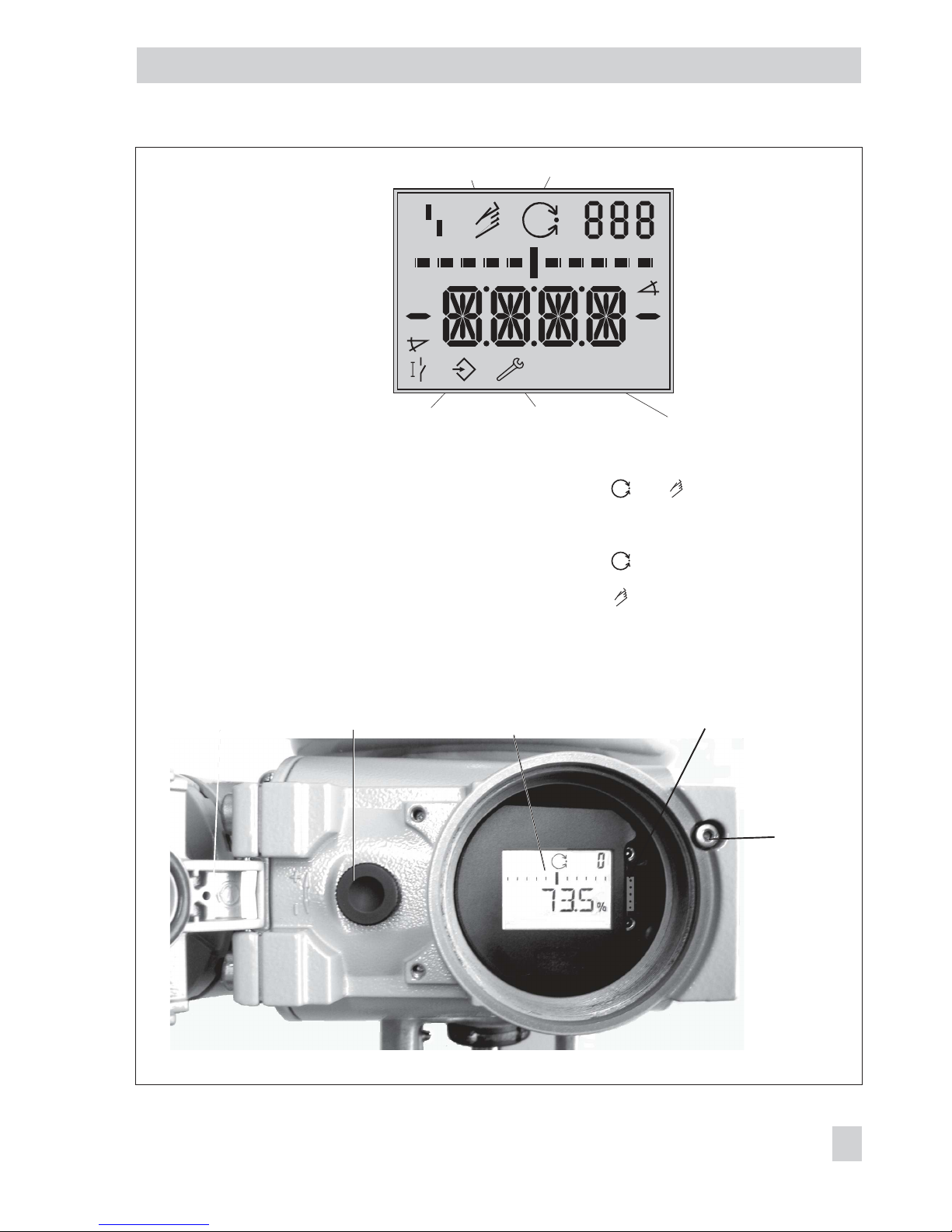
EB 8387-5 EN 39
Operator controls and readings
Retaining
screw
Protective cover Rotary pushbutton LC display Serial interface
and together:
AO Transducer Block is in
MAN operating mode
blinks Emergency mode,
see Code 62
blinks Not initialized
blinks Valve in mechanical
fail-safe position
Fail-safe position
active
Code
Bar elements for
system deviation
or lever position
Units
Condensed state:
Maintenance alarm
Designation
Position
Parameter
Binary input
Configuration
enabled
Manual operation Closed-loop operation
Condensed state:
Maintenance required
Main
-
S
RES Reset
RUN Start
SAFE Fail-safe position
SUb Substitute calibration
TunE Initialization in progress
YES Exists
ZP Zero calibration
tEStinG Self-test
tESt Test function active
ää Increasing/increasing
äæ Increasing/decreasing
AUtO Automatic mode
CL Clockwise
CCL Counterclockwise
Err Error
ESC Escape
MAN Manual setting
MAX Maximum range
NO Not available
NOM Nominal travel
ON On
OFF Off
Readings and their meanings
%
S
mm
%
mm
Fig. 14 · Readings and operator controls
Page 40
7 Start-up – Settings
WARNING!
Attach the positioner, keeping the following
sequence:
1. Mount the positioner on the control valve
2. Connect the supply air
3. Connect the electrical power
4. Perform the start-up settings
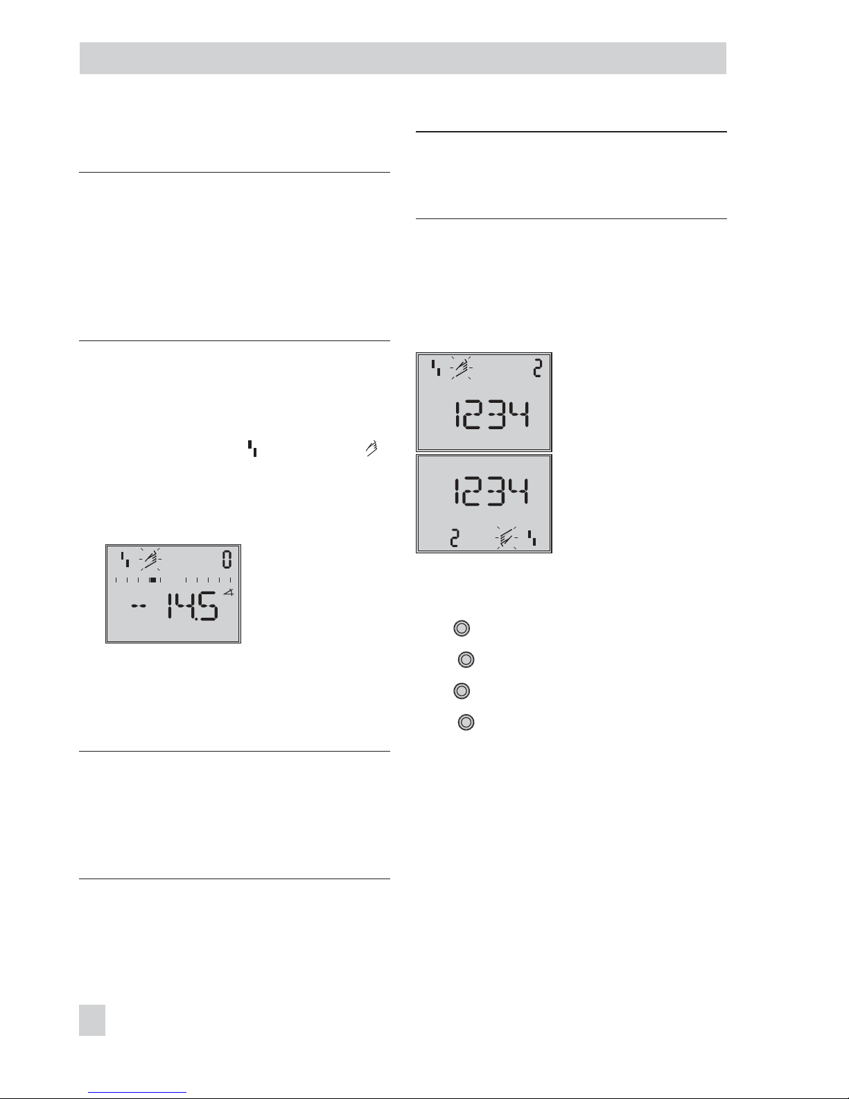
Reading on display after connecting the
electrical auxiliary power:
4
tEStinG runs across the display and then
the fault alarm icon
appears and
blinks on the display when the positioner
has not yet been initialized. The reading
indicates the lever position in degrees in
relation to the longitudinal axis.
Reading when the
positioner has not yet
been initialized
4
Code 0 appears on the display when a
positioner has been initialized. The
positioner is in the last active operating
mode.
WARNING!
The actuator stem moves while the start-up
settings are being performed.
Do not touch the actuator stem or obstruct it
to avoid risk of injury to hands or fingers.
NOTICE
Perform the start-up settings in the same se
-
quence as listed (section 7.1 to section 7.5).
7.1 Adapting the display
The reading on the display can be turned by
180° to adapt it to how the positioner is at
-
tached.
Reading direction for right
attachment of pneumatic
connections
Reading direction for left
attachment of pneumatic
connections
If the display appears upside down, proceed
as follows:
Turn
→
Code 2
Press , Code 2 blinks.
Turn
→
Desired reading direction.
Press
to confirm the reading direction.
7.2 Limiting the signal pressure
If the maximum actuator force may cause
damage to the valve, the signal pressure
must be limited.
40 EB 8387-5 EN
Start-up – Settings
Page 41
NOTICE
Do not activate the pressure limit function in
actuators with fail-safe action AIR TO OPEN
(AtO), e.g. double-acting actuators (OFF =
default).
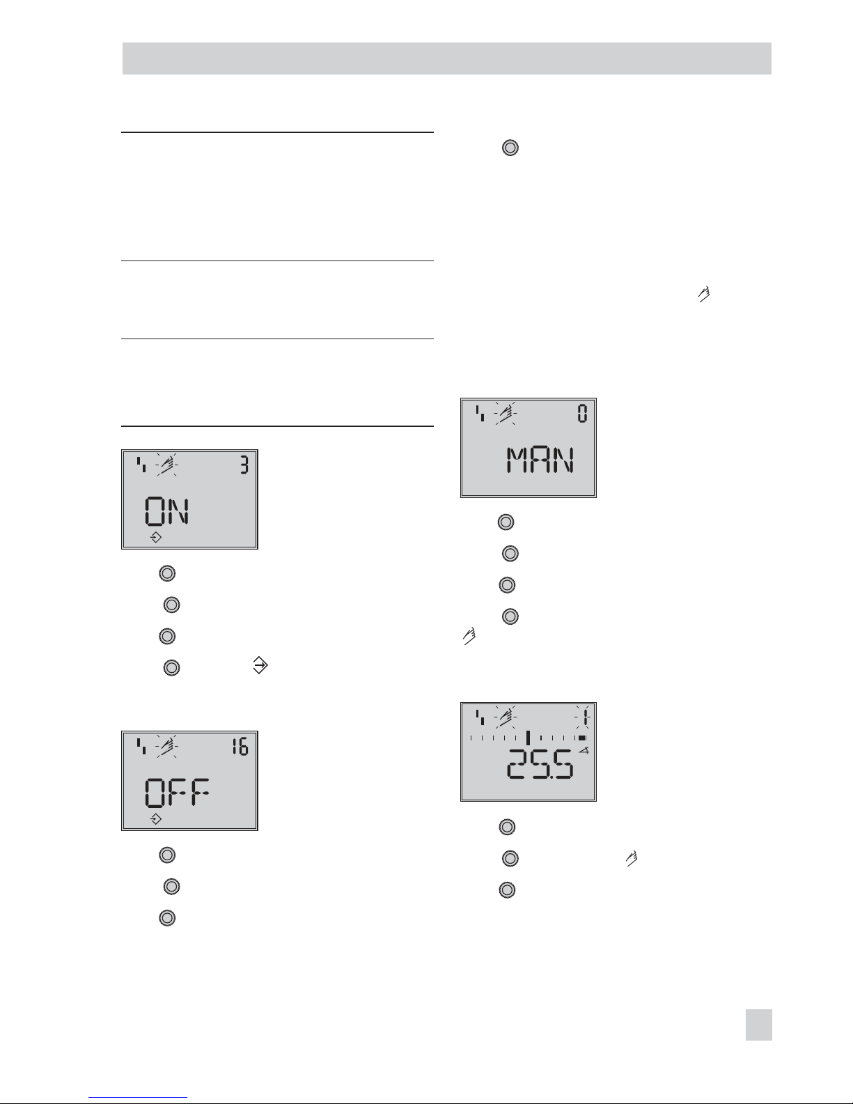
Enable configuration at the positioner before
activating the pressure limit function:
Note: If no settings are entered within
120 seconds, the enabled configuration
function becomes invalid.
Configuration enabled
Default: OFF
Turn
→
Code 3, display: OFF
Press , Code 3 blinks.
Turn
→
ON
Press , display:
Pressure limit function:
Pressure limit
Default: OFF
Turn
→
Code 16
Press , Code 16 blinks.
Turn
until the required pressure limit
(1.4/2.4/3.7 bar) appears.
Press to confirm the pressure limit.
7.3 Checking the operating
range of the positioner
To check the mechanical attachment, the
valve should be moved through the operat
-
ing range of the positioner in the
manual
operating mode using the manual reference
variable w.
Select manual operating mode:
Mode
Default: MAN
Turn
→
Code 0
Press , Code 0 blinks.
Turn
→
MAN
Press to change the positioner to
manual mode.
Checking the operating range:
Manual reference variable
(the current opening angle
appears)
Turn
→
Code 1
Press , Code 1 and blink.
Turn
until the pressure builds up in the
positioner, and the control valve moves to its
end positions to check the travel range/an
-
gle of rotation.
EB 8387-5 EN 41
Start-up – Settings
Page 42
The angle of the lever on the back of the
positioner is indicated on the display.
A horizontal lever (mid-position) is equal to
0°.
To ensure the positioner is working prop
-
erly, the outer bar elements may not blink
while the valve is moving through the oper
ating range.
The manual operating mode can be exited
by pressing the rotary pushbutton ( ).
The permissible range has been exceeded
when the displayed angle is greater than
30°, and the outer right or left bar element
blinks.
The positioner changes to the fail-safe position
SAFE.
A
fter canceling the fail-safe position SAFE
(see section 8.2.2) it is absolutely necessary
to check the lever and pin position as described in section 4.
WARNING!
To avoid personal injury or property dam
age caused by the supply air or electrical
auxiliary power, disconnect the supply air
and electrical auxiliary power (bus line) be
fore exchanging the lever or changing the
pin position.
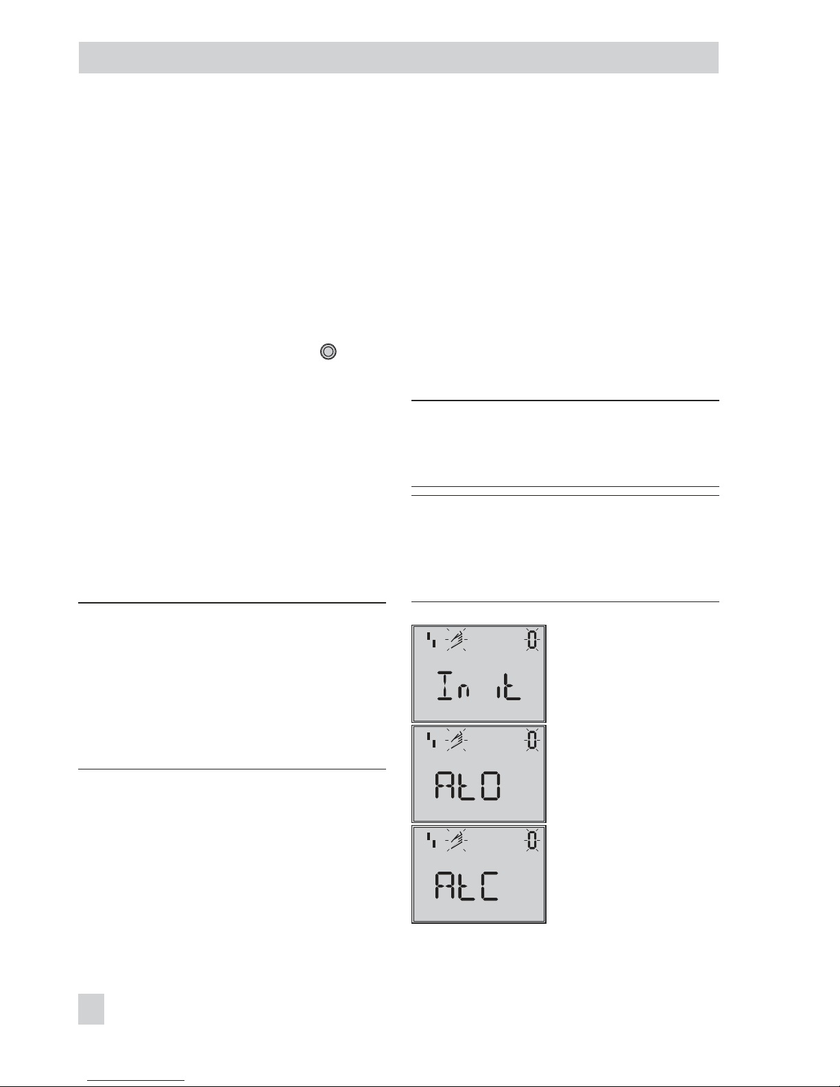
7.4 Determining the fail-safe
position
To adapt the positioner to the operating di
rection of the actuator, the fail-safe position
of the positioner must be determined:
4
AIR TO OPEN (AtO)
Signal pressure opens the valve.
Fail-safe position: Valve CLOSED
4
AIR TO CLOSE (AtC)
S
ignal pressure closes the valve.
Fail-safe position: Valve OPEN
NOTICE
Double-acting actuators must always be set
to AIR TO OPEN (AtO).
Note: The fail-safe position setting remains
set even when the positioner is started up
again after the power supply has been disconnected.
Initialization
Fail-safe position
AIR TO OPEN
Fail-safe position
AIR TO CLOSE
42 EB 8387-5 EN
Start-up – Settings
Page 43
Turn
→
Code 0
Press , display: MAN
Code 0 blinks.
Turn
→
Init
Press .
Turn until the required fail-safe position
appears on the display.
Press to confirm the fail-safe position.
Turn
→
ESC
Press to exit or:
Start initialization as described in sec
-
tion
7.5.
For checking purposes: After the positioner
has been initialized successfully, the valve
closed position is indicated on the positioner
display as 0 %, whereas the valve open position is indicated by 100 %. If this is not the
case, the closing direction has to be adapted
correspondingly and the positioner needs to
be re-initialized.
7.5 Positioner initialization
WARNING!
During initialization, the control valve moves
through its entire travel/angle of rotation
range. Therefore, do not start the initializa
tion procedure while a process is running,
but only during start-up when all shut-off
valves are closed.
Before starting initialization, check the maxi
-
mum permissible signal pressure of the con
-
trol valve. During initialization, the
positioner issues an output signal pressure
up to the maximum supply pressure sup
plied. If necessary, limit the signal pressure
by connecting an upstream pressure reduc
-
ing valve.
NOTICE
If the positioner is mounted onto another ac
tuator or its mounting position is changed,
reset the positioner to its default settings be
-
fore re-initializing it. Refer to section 7.7.
During initialization the positioner adapts it
self optimally to the friction conditions and
the signal pressure requirements of the con
trol valve.
The type and extent of self-adaptation depends on the initialization mode selected:
4
MAX maximum range (standard range)
Initialization mode for simple start-up of
valves with two clearly defined mechani
cal end positions, e.g. three-way valves
(see section 7.5.1)
4
NOM nominal range
Initialization mode for all globe valves
(see section 7.5.2)
4
MAN manually selected range
Initialization mode for globe valves with
an unknown nominal range (see section
7.5.3)
4
SUB substitute calibration (emergency
mode)
This mode allows a positioner to be re
placed while the plant is running, with
the least amount of disruption to the
plant (see section 7.5.4)
EB 8387-5 EN 43
Start-up – Settings
Page 44
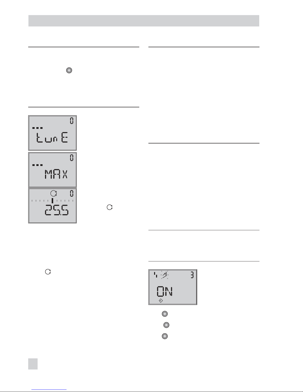
Note: The initialization procedure can be in
-
terrupted while running by pressing the rota
-
ry pushbutton ( ). StOP appears three se
conds long and the positioner then moves to
the fail-safe position.
The fail-safe position can be canceled again
over Code 0.
Alternating displays:
Initialization running
Initialization progress
indicated
(MAX, NOM, MAN or SUB
appears, depending on the
initialization mode selected)
Initialization successful
Positioner in automatic
operating mode
The time required for an initialization
process depends on the stroking speed of
the actuator
and may take several minutes.
After a successful initialization, the
positioner runs in automatic mode indicated
by the closed-loop operation icon.
A malfunctioning leads to the process being
interrupted. The initialization error appears
on the display according to how it has been
classified by the condensed state. See sec
-
tion 8.3 on page 56).
Note: Positioner with extended EXPERT+di
-
agnostics automatically start to plot the refe
-
rence graphs (drive signal y d1 and hystere
-
sis d2) after initialization has been comple
ted. tESt d1 and d2 appear on the display in
alternating sequence.
An unsuccessful plotting of the reference
graphs is indicated on the display by Code
81.
The positioner still works properly, even
though the reference graph plotting has not
been completed successfully.
7.5.1 Initialization based on MAX
maximum range
The positioner determines travel/angle of
rotation of the closing member from the
CLOSED position to the opposite side and
adopts this travel/angle of rotation as the
operating range from 0 to 100 %.
Enable configuration:
Note: If no settings are entered within
120 seconds, the enabled configuration
function becomes invalid.
Configuration enabled
Default: OFF
Turn
→
Code 3, display: OFF
Press , Code 3 blinks.
Turn
→
ON
44 EB 8387-5 EN
Start-up – Settings
%
Page 45
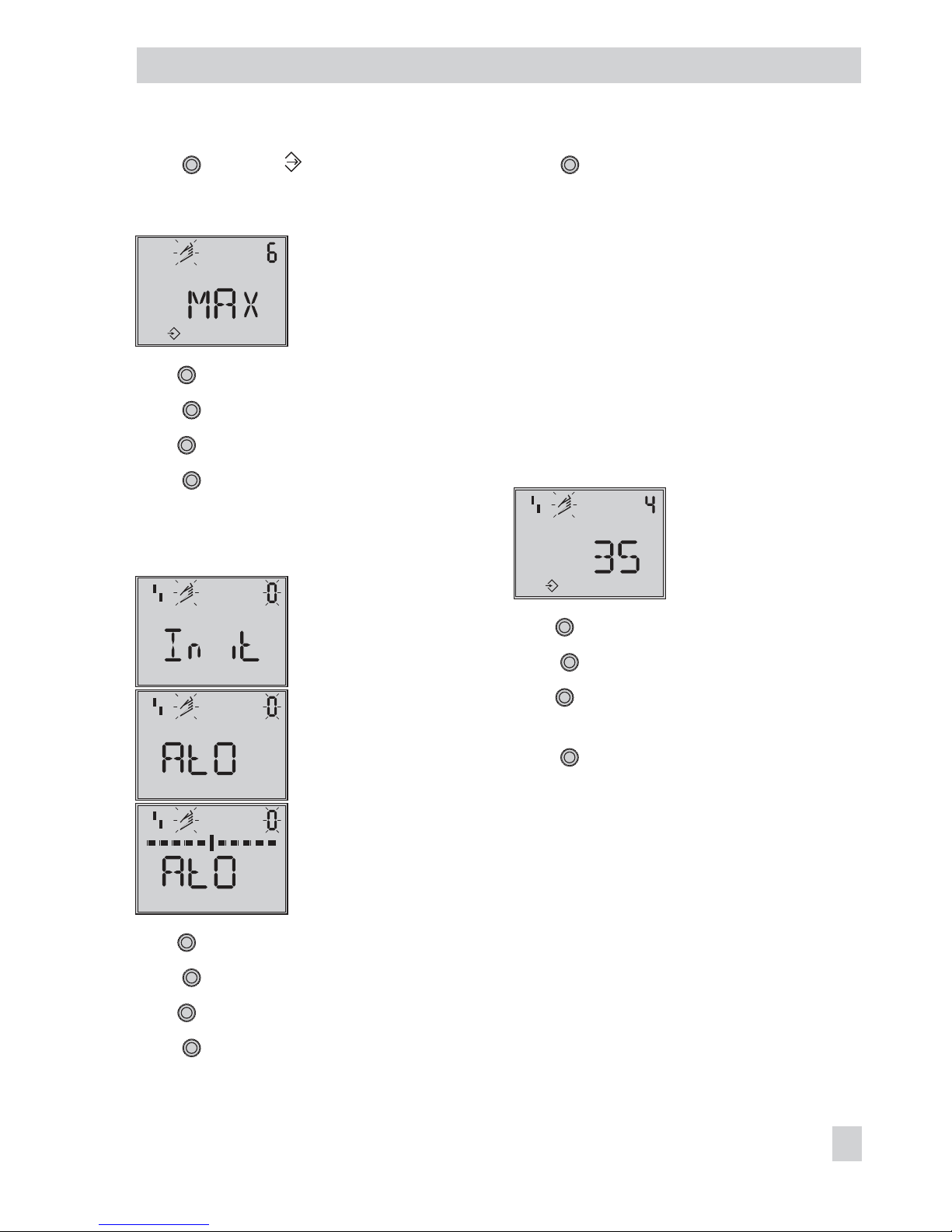
Press , display:
Select initialization mode:
Init mode
Default: MAX
Turn
→
Code 6
Press
Turn
→
MAX
Press to confirm the MAX initialization
mode.
Start initialization:
Initialization
Fail-safe position setting
Progress indicated until
initialization starts
Turn
→
Code 0
Press , Code 0 blinks.
Turn
→
Init
Press . The setting of the fail-safe position
AtO or AtC appears.
Keep
pressed down for 6 seconds.
Initialization starts after the progress indica
-
tion has stopped.
The nominal travel/angle of rotation is indi
-
cated in % after initialization. Code
5 (nomi
nal range) remains locked. The parameters
for travel/angle range start (Code
8) and
travel/angle range end (Code 9) can also
only be displayed and modified in %.
For a reading in mm/°, enter the pin posi
-
tion (Code 4).
Enter pin position:
Pin position
Default: OFF
Turn
→
Code 4
Press , Code 4 blinks.
Turn
→
Pin position on lever (see sec
-
tions on attachment)
Press . The reading of the nominal range
appears in mm/°.
7.5.2 Initialization based on NOM
nominal range
The calibrated sensor allows the effective
valve travel to be set very accurately. During
the initialization process, the positioner
checks whether the control valve can move
through the indicated nominal range (travel
or angle) without collision.
If this is the case, the indicated nominal
range is adopted with the limits of
EB 8387-5 EN 45
Start-up – Settings
mm
Page 46
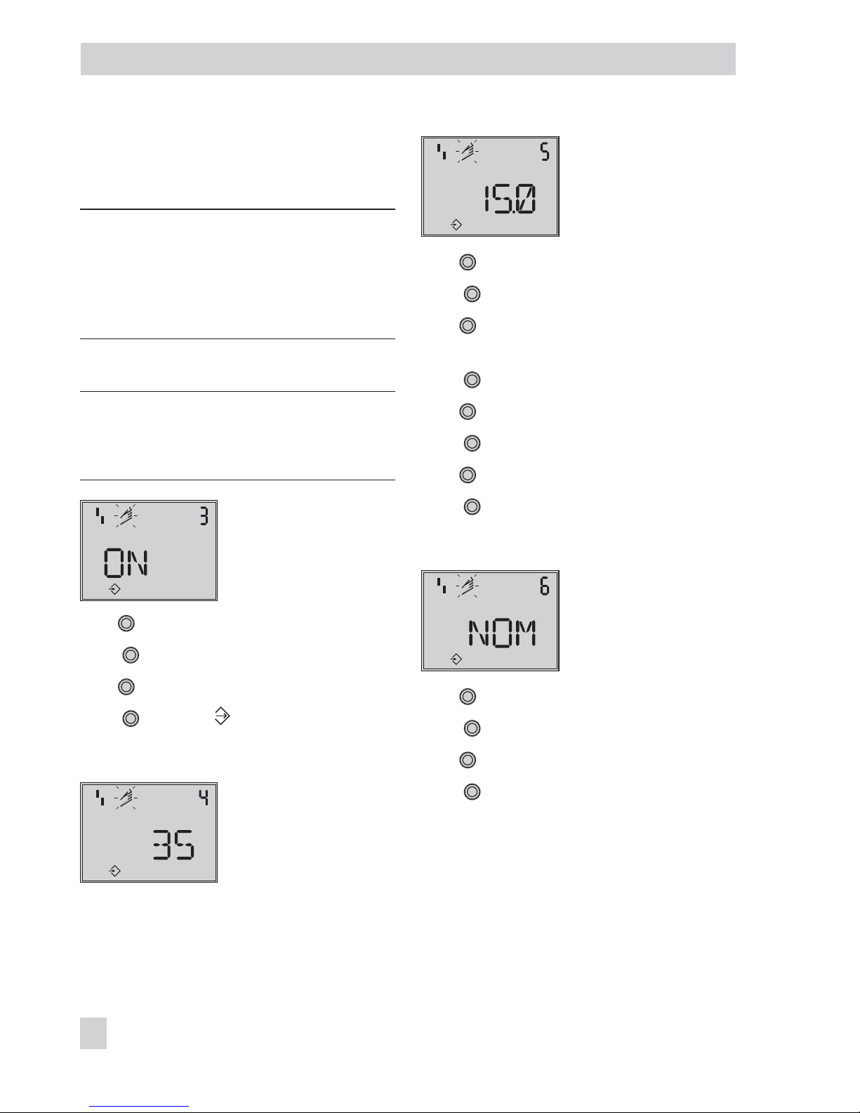
travel/angle range start (Code 8) and
travel/angle range end (Code 9) as the op
-
erating range.
Note: The maximum possible travel must al
-
ways be greater than the nominal travel en
tered. If this is not the case, initialization is
interrupted (error message Code 52) becau
-
se the nominal travel is not achieved.
Enable configuration:
Note: If no settings are entered within
120 seconds, the enabled configuration
function becomes invalid.
Configuration enabled
Default: OFF
Turn
→
Code 3, display: OFF
Press , Code 3 blinks.
Turn
→
ON
Press , display:
Enter pin position and nominal travel:
Pin position
Default: OFF
Nominal range
(with Code 4 = OFF locked)
Turn
→
Code 4
Press , Code 4 blinks.
Turn
→
Pin position on lever (see sec
-
tions on attachment)
Press
.
Turn
→
Code 5
Press , Code 5 blinks.
Turn
→
Nominal valve travel
Press
.
Select initialization mode:
Initialization mode
Default: MAX
Turn
→
Code 6
Press , Code 6 blinks.
Turn
→
NOM
Press to confirm the NOM initialization
mode.
46 EB 8387-5 EN
Start-up – Settings
mm
mm
Page 47
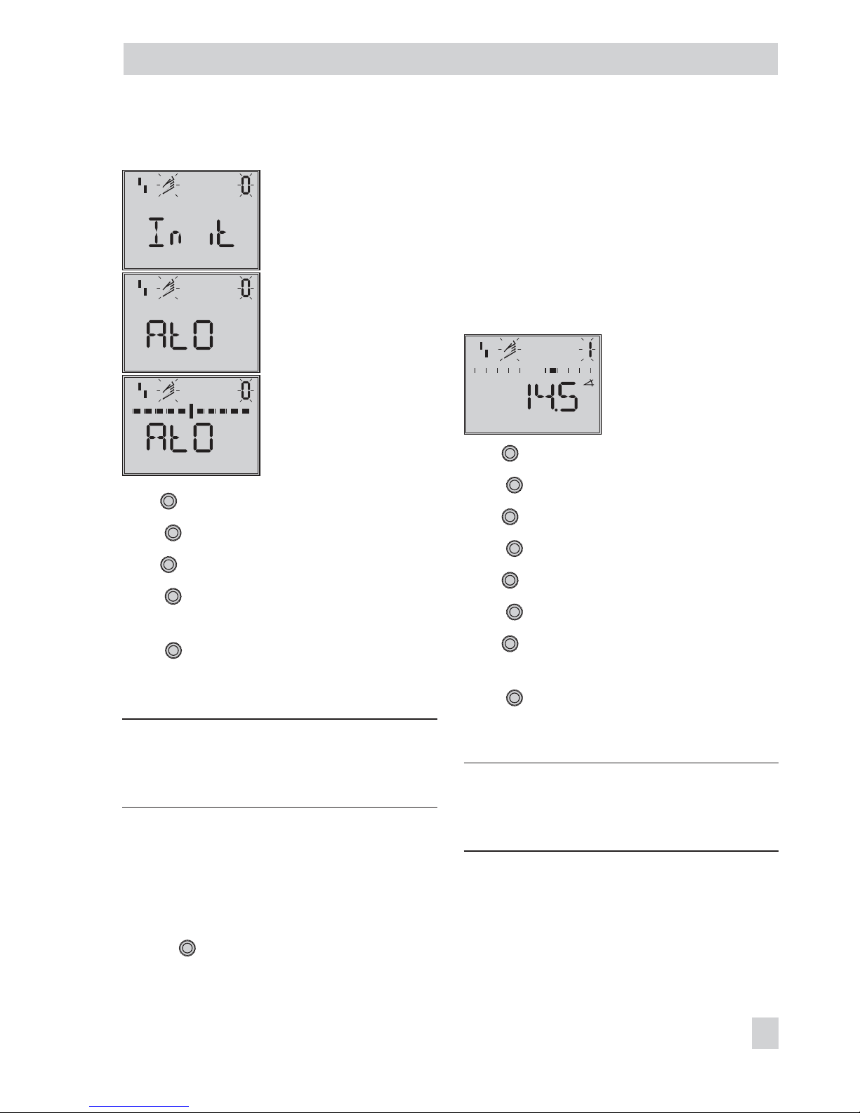
Start initialization:
Initialization
Fail-safe position setting
Progress indicated until
initialization starts
Turn
→
Code 0
Press , Code 0 blinks.
Turn
→
Init
Press . The setting of the fail-safe position
AtO or AtC appears.
Keep
pressed down for 6 seconds.
Initialization starts after the progress indica
-
tion has stopped.
Note: After initialization, check the direction
of action and, if necessary, change it
(Code 7).
7.5.3 Initialization based on MAN
manually selected range
Before starting initialization, move the con
trol valve manually to the OPEN position by
turning
in small steps. The valve must
move to the required valve position with a
monotonically increasing signal pressure.
The positioner calculates the differential
travel/angle using the OPEN and CLOSED
positions and adopts it as the operating
range with limits of travel/angle range start
(Code
8) and travel/angle range end
(Code 9).
Enter OPEN position:
Manual reference variable
(the current angle of rotation
is displayed)
Turn
→
Code 0
Press , Code 0 blinks.
Turn
→
MAN
Press .
Turn
→
Code 1
Press , Code 1 blinks.
Turn
until the OPEN position of the valve
is reached.
Press to confirm the OPEN position.
Enable configuration:
Note: If no settings are entered within
120 seconds, the enabled configuration
function becomes invalid.
EB 8387-5 EN 47
Start-up – Settings
Page 48
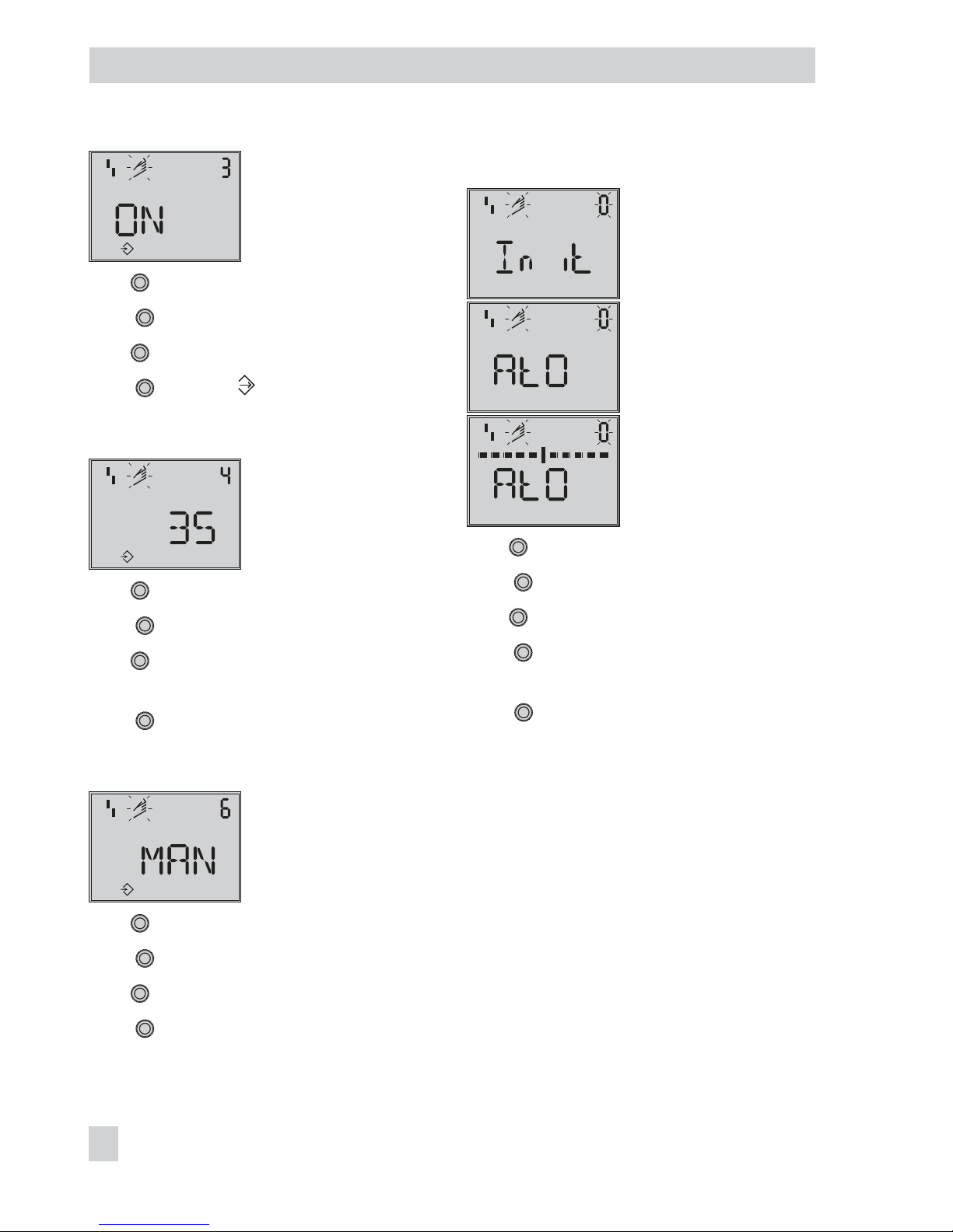
Configuration enabled
Default: OFF
Turn
→
Code 3, display: OFF
Press , Code 3 blinks.
Turn
→
ON
Press , display:
Enter pin position:
Pin position
Default: OFF
Turn
→
Code 4
Press , Code 4 blinks.
Turn
→
Pin position on lever (see sec
-
tions on attachment).
Press .
Select initialization mode:
Initialization mode
Default: MAX
Turn
→
Code 6
Press , Code 6 blinks.
Turn
→
MAN
Press to confirm the MAN initialization
mode.
Start initialization:
Initialization
Fail-safe position setting
Progress indicated until
initialization starts
Turn
→
Code 0
Press , Code 0 blinks.
Turn
→
Init
Press . The setting of the fail-safe position
AtO or AtC appears.
Keep pressed down for 6 seconds.
Initialization starts after the progress indica
-
tion has stopped.
7.5.4 SUB substitute calibration
A complete initialization procedure takes
several minutes and requires the valve to
move through its entire travel range several
times. This initialization mode, however, is
an emergency mode, in which the control
parameters are estimated and not deter
mined by an initialization procedure. As a
result, a high level of accuracy cannot be
expected.
48 EB 8387-5 EN
Start-up – Settings
mm
Page 49
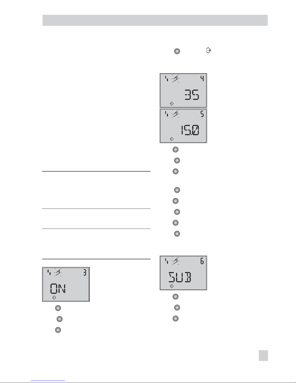
You should always select a different initial
-
ization mode if the plant allows it.
The SUB initialization mode is used to re
place a positioner while the process is
running. For this purpose, the control valve
is usually fixed mechanically in a certain po
-
sition, or pneumatically by means of a pres
sure signal which is routed to the actuator
externally. The blocking position ensures
that the plant continues to operate with this
valve position.
By entering the blocking position (Code
35),
closing direction (Code 34), pin position
(Code 4), nominal range (Code 5) and di
rection of action (Code 7), the positioner
can calculate the positioner configuration.
NOTICE
Perform a reset before re-initializing the
positioner if the substitute positioner has already been initialized. Refer to section .
Enable configuration:
Note: If no settings are entered within
120 seconds, the enabled configuration
function becomes invalid.
Configuration enabled
Default: OFF
Turn
→
Code 3, display: OFF
Press , Code 3 blinks.
Turn
→
ON
Press , display:
Enter pin position and nominal travel:
Pin position
Default: OFF
Nominal range
(with Code 4 = OFF locked)
Turn
→
Code 4
Press , Code 4 blinks.
Turn
→
Pin position on lever (see sec-
tions on attachment).
Press .
Turn
→
Code 5
Press , Code 5 blinks.
Turn
→
Nominal travel of the valve
Press .
Select initialization mode:
Initialization mode
Default: MAX
Turn
→
Code 6
Press .
Turn
→
SUB
EB 8387-5 EN 49
Start-up – Settings
mm
mm
Page 50
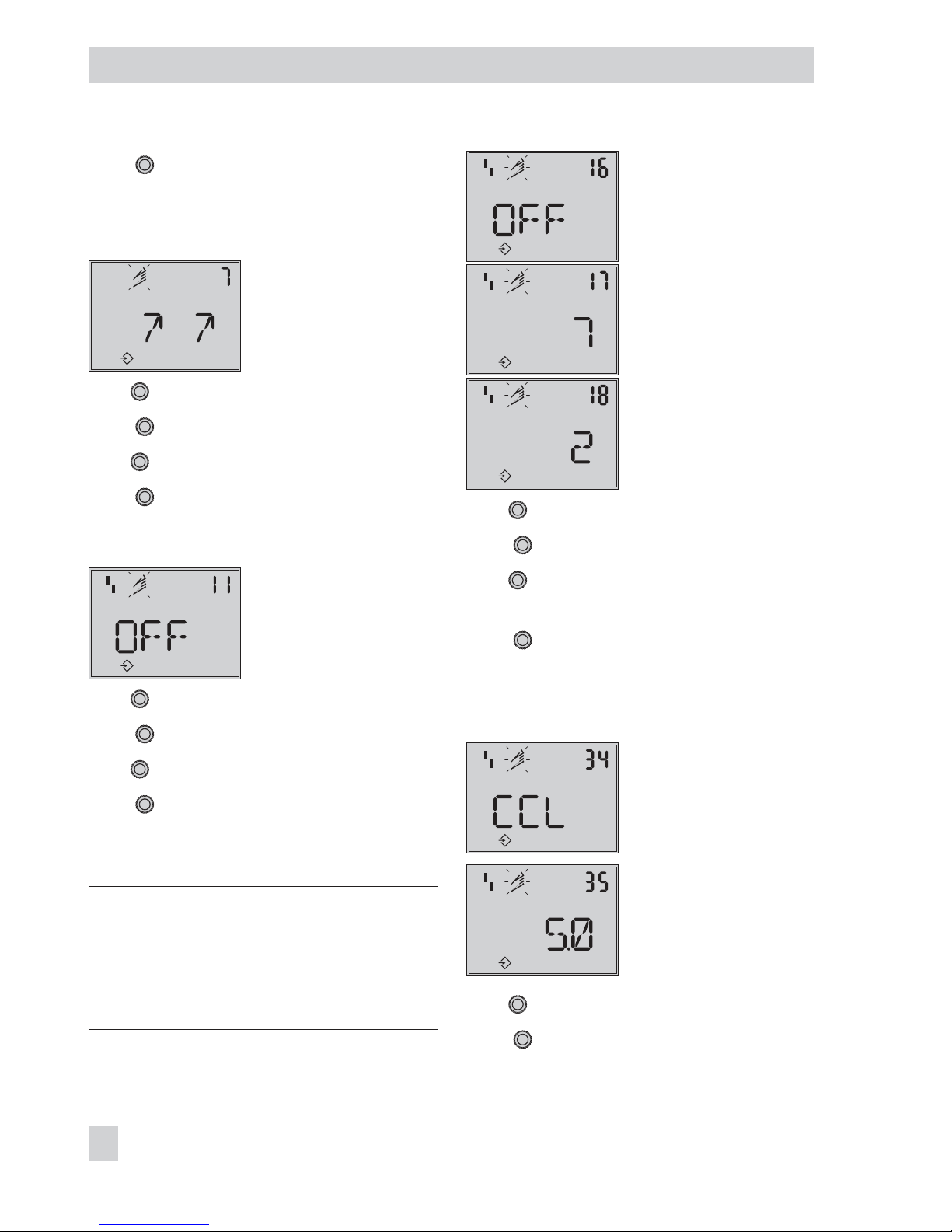
Press to confirm the SUB initialization
mode.
Enter direction of action:
Direction of action
Default: ää
Turn
→
Code 7
Press , Code 7 blinks.
Turn
→
Direction of action (ää/äæ)
Press .
Deactivate travel limit:
Travel limit
Default: 100.0
Turn
→
Code 11
Press , Code 11 blinks.
Turn
→
OFF
Press .
Change pressure limit and control parame
-
ters:
Note: Do not change the pressure limit
(Code 16). Only change the control para
meters KP(Code 17) and TV(Code 18) if the
settings of the replaced positioner are
known.
Pressure limit
Default: OFF
KP stage
Default: 7
TV stage
Default: 2
Turn
→
Code 16/17/18
Press , Code16/17/18 blinks.
Turn
and set the selected control param-
eter.
Press to confirm setting.
Enter closing direction and blocking position:
Closing position
Direction of rotation causing
the valve to move to the
CLOSED position (view onto
positioner display)
Default: CCL
(counterclockwise)
Blocking position
Default: 0
Turn
→
Code 34
Press , Code 34 blinks.
50 EB 8387-5 EN
Start-up – Settings
mm
Page 51
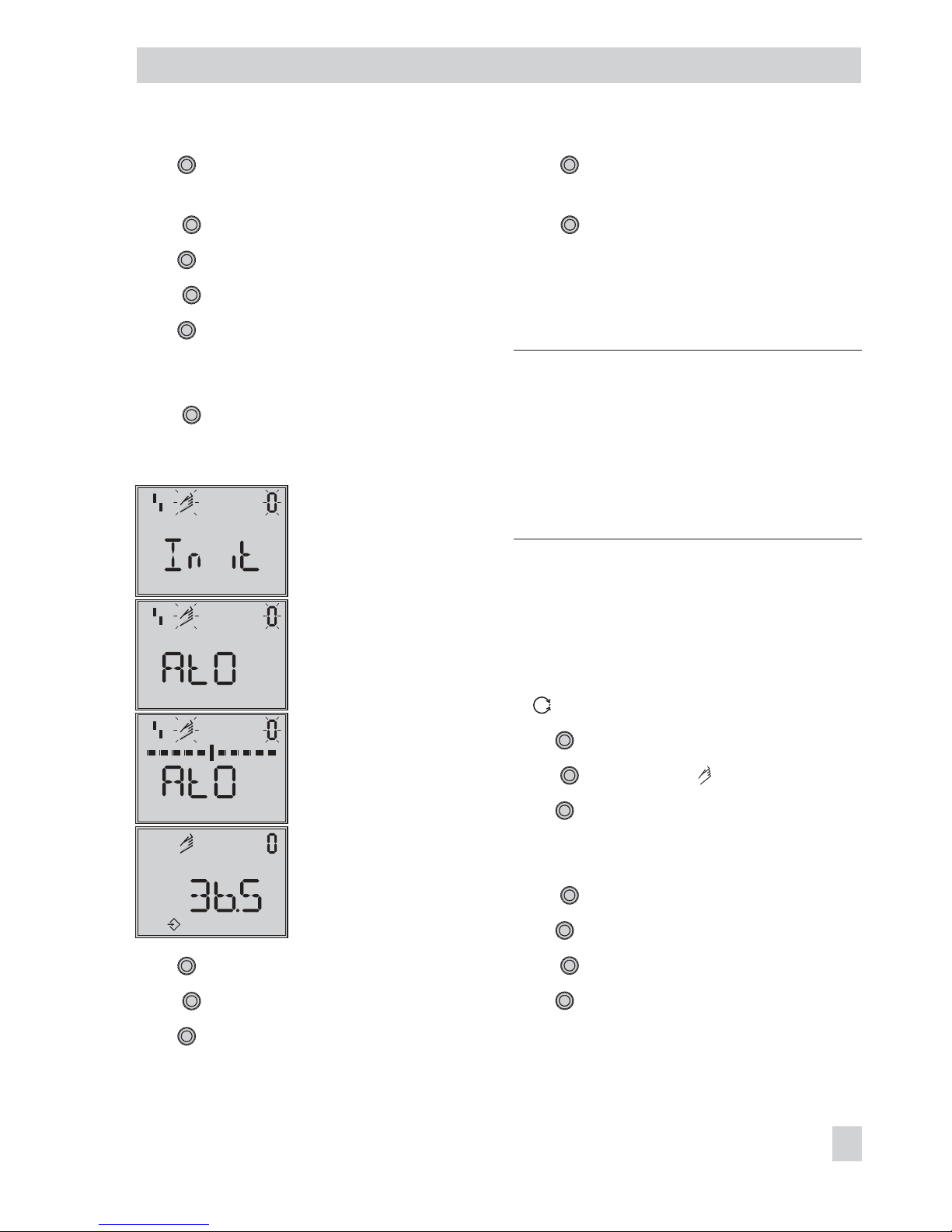
Turn
→
Closing direction (CCL counter
-
clockwise/CL clockwise)
Press .
Turn
→
Code 35
Press , Code 35 blinks.
Turn
→
Blocking position, e.g. 5 mm
(read off at travel indicator scale of the
blocked valve or measure with a ruler)
Press .
Start initialization:
Initialization
Fail-safe position setting
Progress indicated until
initialization starts
Blocking position
Turn
→
Code 0
Press , Code 0 blinks.
Turn
→
Init
Press . The setting of the fail-safe position
AtO or AtC appears.
Keep
pressed down for 6 seconds.
Initialization starts after the progress indica
tion has stopped.
The operating mode changes to MAN.
The blocking position appears.
Note: As initialization has not been carried
out completely, the error code 76 (no emer
gency mode) and possibly also error code
57 (control loop) may appear on the dis
play.
These messages do not influence the positio
-
ner’s readiness for operation.
Cancel the blocking position and change to
automatic operating mode:
For the positioner to follow its reference
variable again, the blocking position must
be canceled and the positioner must be set
to
automatic operating mode.
Turn
→
Code 1
Press , Code 1 and blink.
Turn until the pressure in the positioner
builds up and the valve moves slightly past
the blocking position.
Press to cancel the blocking position.
Turn
→
Code 0
Press , Code 0 blinks.
Turn
→
AUtO
EB 8387-5 EN 51
Start-up – Settings
%
Page 52
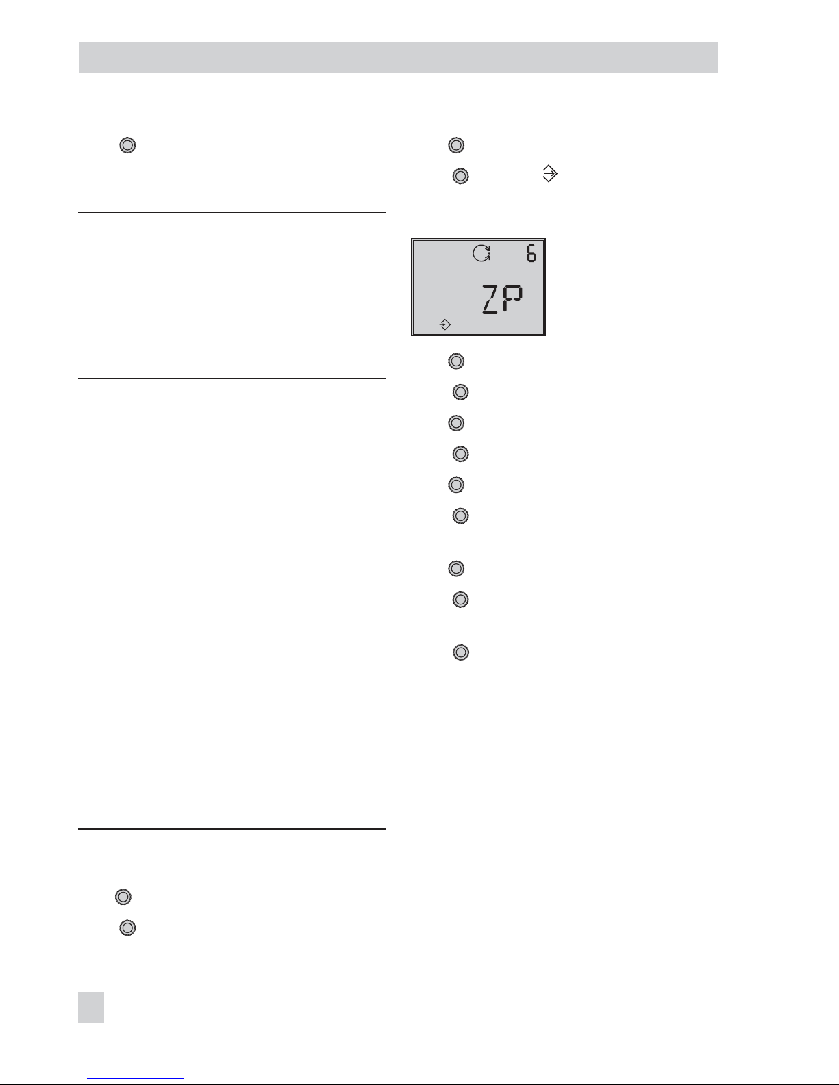
Press . The positioner changes to the au
tomatic operating mode. The current valve
position is indicated in % on the display.
Note: If the positioner shows a tendency to
hunt in automatic operating mode, the pa
-
rameters KPand TVmust be slightly cor
-
rected. Proceed as follows:
–
Set TV(Code 18) to 4.
–
Reduce KP(Code 17) until the positioner
shows a stable behavior.
Zero point correction
Finally, if process operations allow it, the
zero point must be calibrated as described
in section
7.6.
7.6 Zero calibration
In case of discrepancies with the closing position of the valve, e.g. with soft-sealed
plugs, it may become necessary to
recalibrate the zero point.
NOTICE
The valve briefly moves from the current
travel/angle of rotation position to the
closed position.
Note: The supply air must be connected to
peform a zero calibration.
Enable configuration:
Turn
→
Code 3, display: OFF
Press , Code 3 blinks.
Turn
→
ON
Press , display:
Perform zero calibration:
Initialization mode
Default: MAX
Turn
→
Code 6
Press , Code 6 blinks.
Turn
→
ZP
Press .
Turn
→
Code 0
Press .
Display: MAN, Code 0 blinks.
Turn
→
Init
Press . The setting of the fail-safe position
AtO or AtC appears.
Keep
pressed down for 6 seconds.
Zero calibration is started, the positioner
moves the control valve to the CLOSED posi
tion and recalibrates the internal electrical
zero point.
52 EB 8387-5 EN
Start-up – Settings
Page 53
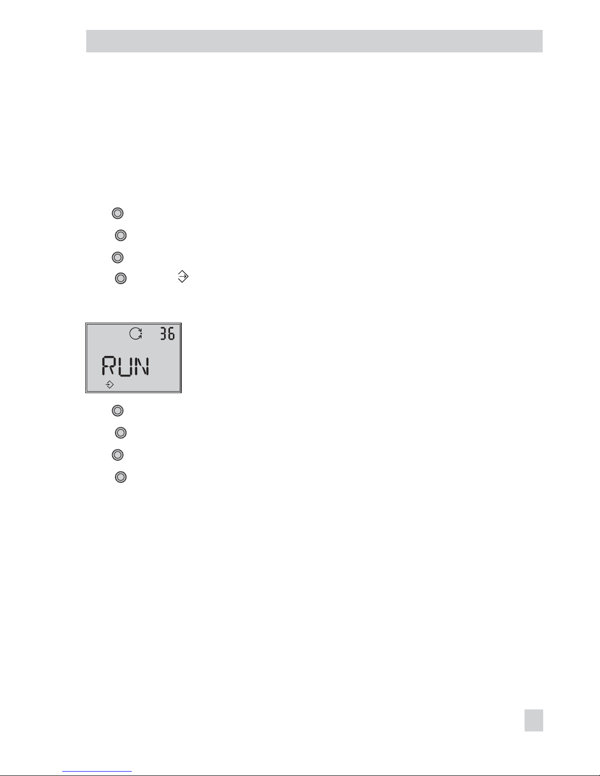
7.7 Reset to default values
This function resets all parameters to the fac
tory default values (see code list in
section 11).
Enable configuration:
Turn
→
Code 3, display: OFF
Press , Code 3 blinks.
Turn
→
ON
Press , display:
Reset start-up parameters:
Reset
Default: OFF
Turn
→
Code 36, display: OFF
Press , Code 3 blinks.
Turn
→
RUN
Press . All start-up parameters are reset
to their default values.
EB 8387-5 EN 53
Start-up – Settings
Page 54
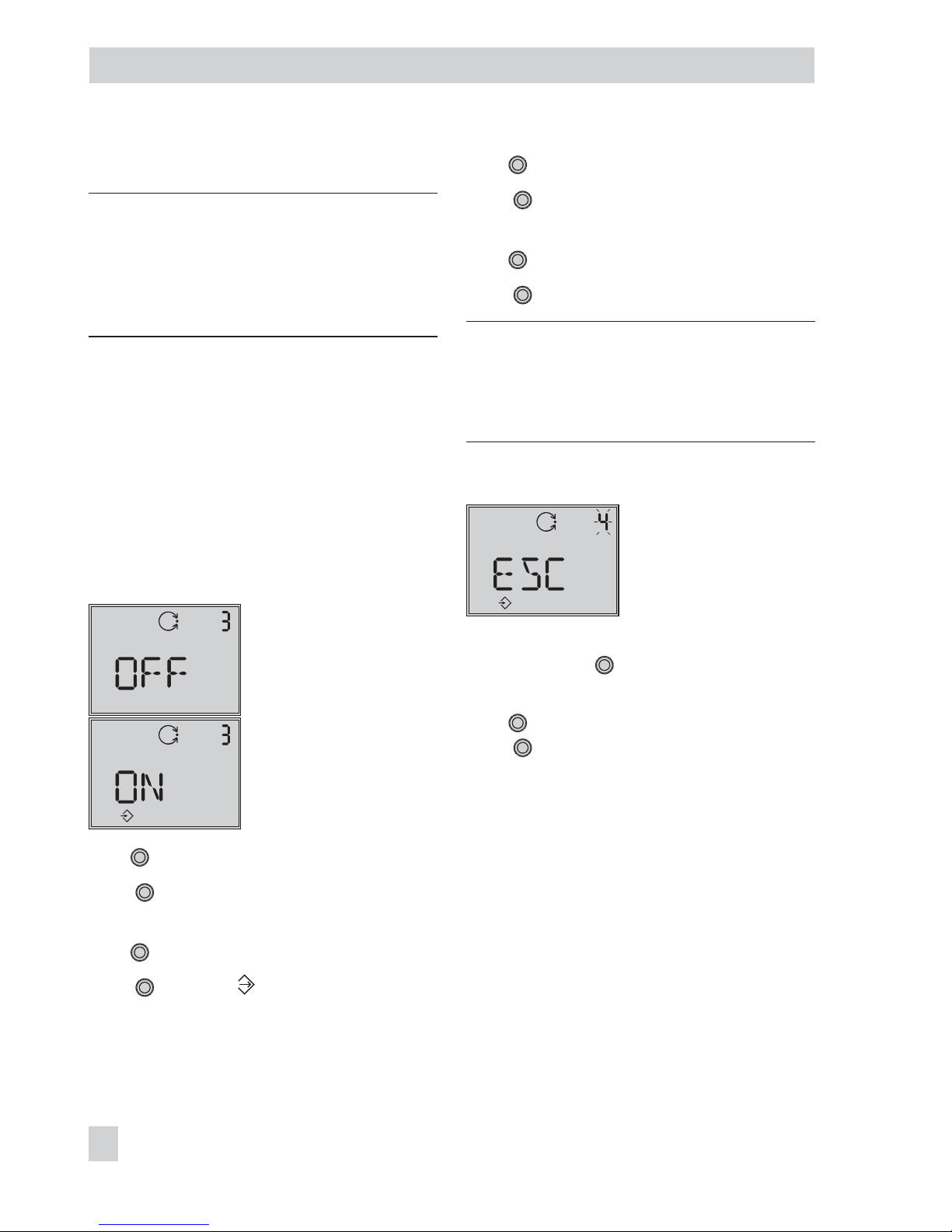
8 Operation
WARNING!
The actuator stem moves while the positioner
is being operated.
Do not touch the actuator stem or obstruct it
to avoid risk of injury to hands or fingers.
8.1 Enabling and selecting
parameters
All codes with their meanings and default
settings are listed in the code list in sec
tion 11 on page 59 onwards.
The codes which are marked with an asterisk (*) must be enabled with Code 3 before
the associated parameters can be configured as described below.
Code
3
Configuration
not enabled
Configuration
enabled
Turn
→
Code 3, display: OFF
Press , Code 3 blinks
Change the setting of Code 3.
Turn
→
ON
Press , display:
The configuration is enabled.
You can now configure codes one after the
other:
Turn
and select the required code.
Press to access the selected code. The
code number starts to blink.
Turn and select the setting.
Press to confirm the selected setting.
Note: If no settings are entered within 120
seconds, the enabled configuration function
becomes invalid and the display resets to
Code 0.
Canceling the setting
Canceling the setting
To cancel a value before it is confirmed (rotary pushbutton
) without the value you
have just selected being adopted:
Turn
→
ESC
Press to confirm the cancelation.
The entry is completed without the value you
have just selected being adopted.
54 EB 8387-5 EN
Operation
Page 55
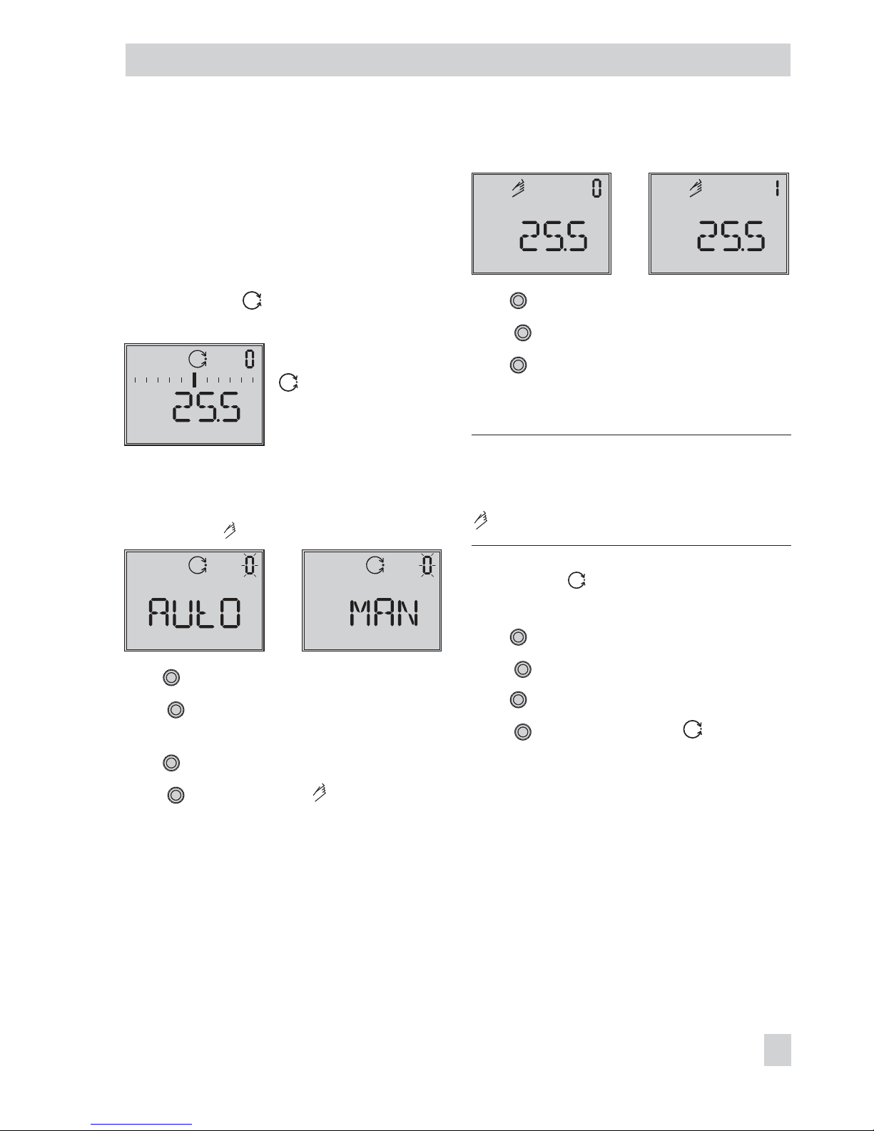
8.2 Operating modes
8.2.1 Automatic and manual
operating modes
After initialization has been completed suc
cessfully for the first time, the positioner is
automatically in automatic operating
mode.
automatic operating
mode
Switching to manual operating mode
Turn
→
Code 0
Press , display: AUtO,
Code 0 blinks.
Turn
→
MAN
Press to switchover to manual operat
ing mode.
The switchover is smooth since the manual
operating mode starts up with the set point
last used during automatic operating mode.
The current position is displayed in %.
Adjust the manual reference variable
Turn
→
Code
1
Press , Code 1 blinks.
Turn until the positioner has built up
enough pressure and the control valve
moves to the required position.
Note: If no settings are entered within
approx. two minutes, the positioner auto
-
matically returns to Code 0, but remains in
manual operating mode.
Switching to automatic operating
mode:
Turn
→
Code 0
Press , Code 0 blinks.
Turn
→
AUtO
Press to switchover to the automatic
operating mode.
EB 8387-5 EN 55
Operation
%
%
%
Page 56
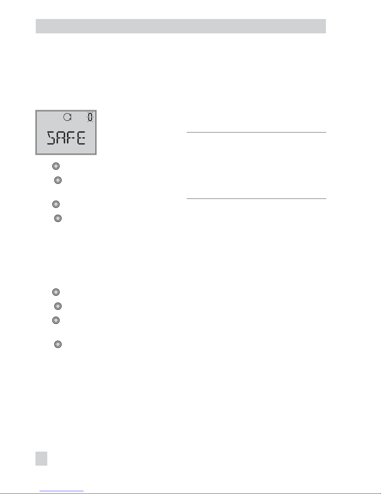
8.2.2 SAFE – Fail-safe position
If you want to move the valve to fail-safe po
-
sition determined during start-up (see sec
-
tion 7.4), proceed as follows:
Turn
→
Code 0
Press , display: current operating mode
(AUtO or MAN), Code 0 blinks.
Turn
→
SAFE
Press , display: S
The valve moves to the fail-safe position.
If the positioner is initialized, the current
valve position is indicated on the display in
%.
Exit the fail-safe position
Turn
→
Code 0
Press , Code 0 blinks.
Turn
and select the required operating
mode AUtO or MAN.
Press .
The positioner switches to the operating
mode selected.
8.3 Malfunction/maintenance
alarm
All status messages and fault alarms are as
signed to a classified status in the positioner.
The default settings of the status classifica
-
tion are listed in the code list.
Note: The classification of the status
messages can be changed in TROVIS-VIEW
and over the parameters in the DD file.
Refer to the Configuration Manual
KH 8387-5 on the supplied CD-ROM
(CD 8387-5) for more information.
To provide a better overview, the classified
alarms are summarized in a condensed
state. The following status messages are
available:
4
Maintenance alarm
The positioner cannot perform its control
task due to a functional fault in the de
-
vice or in one of its peripherals or an ini
tialization has not yet been successfully
completed.
4
Maintenance required
The positioner still performs its control
task (with restrictions). A maintenance
requirement or above average wear has
been determined. The wear tolerance will
soon be exhausted or is reducing at a
faster rate than expected. Maintenance is
necessary in the medium term.
4
Maintenance demanded
The positioner still performs its control
task (with restrictions). A maintenance
demand or above average wear has
been determined. The wear tolerance will
soon be exhausted or is reducing at a
56 EB 8387-5 EN
Operation
Page 57
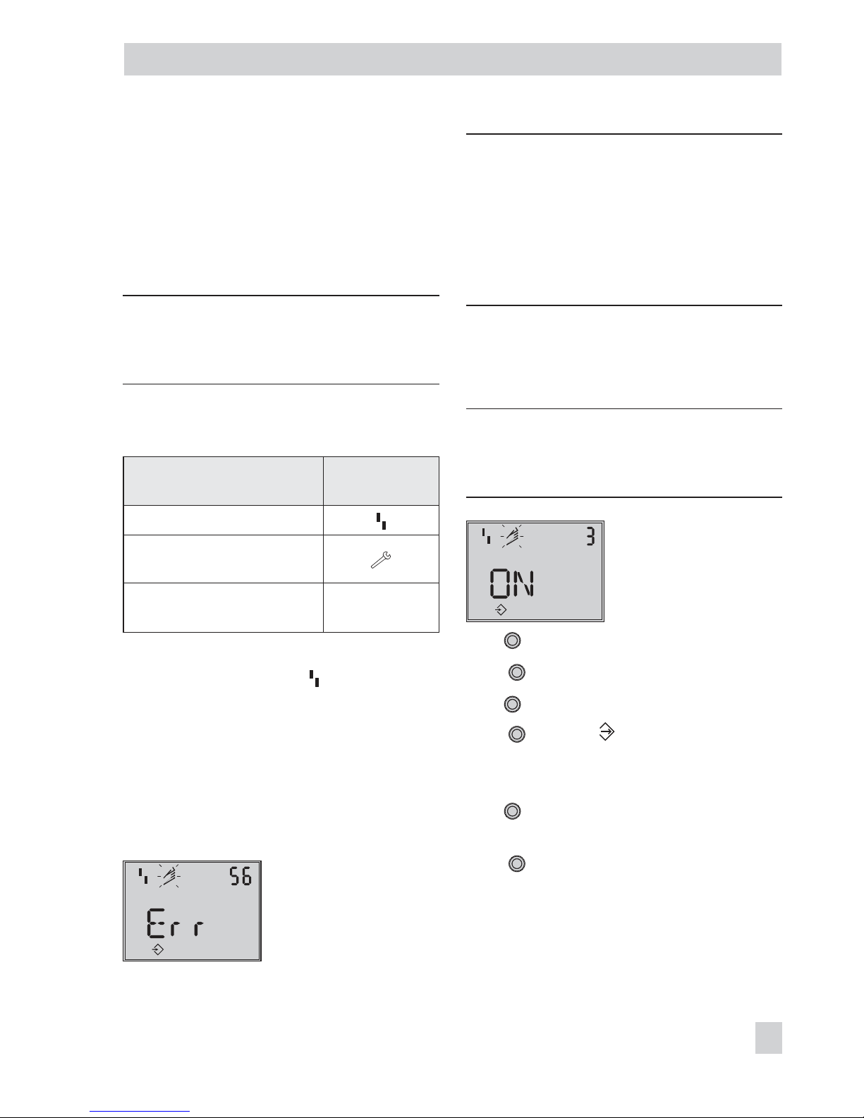
faster rate than expected. Maintenance
is necessary in the short term.
4
Function check
Test or calibration procedures are being
performed. The positioner is temporarily
unable to perform its control task until
this procedure is completed
Note: If an event is assigned to the “No
message” status, this event does not have
any effect on the condensed state.
The condensed state is represented by the
following icons:
Condensed state
Positioner
display
Maintenance alarm
Maintenance required/
Maintenance demanded
Function check
tESting, TunE or
tESt
If the positioner has not been initialized, the
maintenance alarm icon ( ) appears on
the display as the positioner cannot follow
its reference variable.
If fault alarms exist, the possible source of
error is displayed in Code 49 onwards. In
this case, Err appears on the display.
The cause and recommended action are
listed in the code list (section 11).
Error: Pin position
Note: The optional EXPERT+valve diagnos
tics generate further diagnostic messages
which are included in the condensed state
according on how they have been classified.
A diagnostic alarm generated by the ex
-
tended EXPERT
+
diagnostics is issued by
Code 79.
8.3.1 Confirming error messages
Enable configuration:
Note: If no settings are entered within
120 seconds, the enabled configuration
function becomes invalid.
Configuration enabled
Standard: OFF
Turn
→
Code 3, display: OFF
Press , Code 3 blinks.
Turn
→
ON
Press , display:
Confirming alarm:
Turn
→
Error code that is to be con
-
firmed.
Press
to confirm the errror message.
EB 8387-5 EN 57
Operation
S
Page 58

9 Maintenance
The positioner does not require any mainte
nance.
There are filters with a 100µm mesh size in
the pneumatic connections for supply and
output which can be removed and cleaned,
if required.
The maintenance instructions of any up
stream supply air pressure reducing stations
must be observed.
10 Servicing explosion-protected
devices
If a part of the positioner on which the ex
-
plosion protection is based needs to be ser
viced, the positioner must not be put back
into operation until an expert has inspected
the device according to explosion protection
requirements, has issued a certificate stating
this or given the device a mark of confor
mity.
Inspection by an expert is not required if the
manufacturer performs a routine test on the
device prior to putting it back into opera
tion. The passing of the routine test must be
documented by attaching a mark of confor
-
mity to the device.
58 EB 8387-5 EN
Maintenance
Page 59

11 Code list
Code
no.
Parameter – Display, values
[default setting]
Description
Note: Codes with marked with an asterisk (*) must be enabled with Code 3 prior to configuration.
0
Operating mode
[MAN]
AUtO · SAFE
ESC
AUtO Automatic mode
MAN Manual mode
SAFE Fail-safe position
ESC Escape
In MAN and AUtO mode, the system deviation is represented by
bar elements on the display.
If the positioner has been initialized, the numerical reading indi
cates the valve position or the angle of rotation in %, otherwise
the position of the lever in relation to the central axis is displayed
in degrees °.
Switchover from automatic to manual mode is smooth.
In fail-safe position, the S icon appears on the display.
Init
AtO · AtC
Init Start initialization
Determine fail-safe position:
AtO: AIR TO OPEN (valve CLOSED in fail-safe position) or
AtC: AIR TO CLOSE (valve OPEN in fail-safe position)
1
Manual reference variable
w
0 to 100 [0] %
of the nominal range
Setting the manual reference variable w
The current travel/angle is displayed in % when the positioner
has been initialized, otherwise the position of the lever in relation
to the central axis is indicated in degrees °.
Can only be selected when Code 0 = MAN.
2
Reading direction
[Normal] or upside down
ESC
The reading direction of the display is turned by 180°.
3
Enable configuration
[OFF]
ON
ESC
Enables the option to modify data (automatically deactivated when
the rotary pushbutton has not been operated for 120 s.)
FF blinks on the display when the on-site operation is locked over
the FF network.
Codes marked with an asterisk (*) can only be read and not
overwritten.
Codes can also only be read over the SSP interface.
EB 8387-5 EN 59
Code list
Page 60

Code
no.
Parameter – Display, values
[default setting]
Description
Note: Codes with marked with an asterisk (*) must be enabled with Code 3 prior to configuration.
4*
Pin position
[OFF]
17, 25, 35, 50, 70, 100,
200 mm
90° with rotary actuators
ESC
Note! If you select a pin
position in Code 4 that is too
small, the positioner switches
to the fail-safe position
(SAFE mode) for reasons of
safety.
The follower pin must be inserted into the correct pin position ac
-
cording to the valve travel/angle of rotation.
The pin position must be entered for initialization using NOM or
SUb.
Pin position Standard Adjustment range
Code 4 Code 5 Code 5
17 7.5 3.6 to 17.7
25 7.5 5.0 to 25.0
35 15.0 7.0 to 35.4
50 30.0 10.0 to 50.0
70 40.0 14.0 to 70.7
100 60.0 20.0 to 100.0
200 120.0 40.0 to 200.0
90° 90.0 24.0 to 100.0
5*
Nominal range
mm or angle °
ESC
For initialization using NOM or SUb, the nominal travel/angle of
rotation of the valve must be entered.
The permissible adjustment range depends on the pin position
according to the table for Code 4.
Code 5 is generally locked until Code 4 is set to OFF, i.e. after a
pin position has been entered, Code 5 can be configured.
After initialization has been successfully completed, the max
-
imum nominal travel/angle reached on initialization is dis
-
played.
6*
Initialization mode
[MAX]
NOM · MAN · SUb · ZP
ESC
Select the initialization mode
MAX: Maximum range of the control valve, the travel/angle of
the closure member from the CLOSED position to the op
-
posite stop in the actuator.
NOM: Nominal range of the control valve, the travel/angle of
the closure member measured from the CLOSED position
to the indicated OPEN position.
MAN: Manually selected range
SUb: Substitute calibration (emergency mode)
ZP: Zero calibration
60 EB 8387-5 EN
Code list
Page 61

Code
no.
Parameter – Display, values
[default setting]
Description
Note: Codes with marked with an asterisk (*) must be enabled with Code 3 prior to configuration.
7*
Direction of action
[ää]
äæ
ESC
Direction of action of the reference variable w in relation to the
travel/angle of rotation x (increasing/increasing or in
-
creasing/decreasing).
Automatic adaptation:
AIR TO OPEN: After initialization, the direction of action remains
increasing/increasing (ää), a globe valve opens as the
reference variable increases.
AIR TO CLOSE: After initialization, the direction of action
changes to increasing/decreasing (äæ), a globe valve
closes as the reference variable increases.
8*
Travel/angle range start
(lower x-range value)
0.0 to 80.0 [0.0] % of the
nominal range
Specified in mm or angle ° provided
Code 4 is set
ESC
Starting value for the travel/angle of rotation in the nominal or
operating range.
The operating range is the actual travel/angle of the control
valve and is limited by the travel/angle range start (Code 8) and
the travel/angle range end (Code 9).
Usually, the operating range and the nominal range are identical. The nominal range can be limited to the operating range
by the travel/angle range start and end. Value is displayed or
must be entered.
The characteristic is adapted.
See also the example in Code 9.
9*
Travel/angle range end
(upper x-range value)
20.0 to 100.0 [100.0] % of
the nominal range
Specified in mm or angle ° provided
Code 4 is set
ESC
End value for the travel/angle of rotation in the nominal or oper
-
ating range. Value is displayed or must be entered.
The characteristic is adapted.
Example: The operating range is modified, for example, to limit
the range of a control valve which has been sized too large. For
this function, the entire resolution range of the reference variable
is converted to the new limits. 0 % on the display corresponds to
the adjusted lower limit and 100 % to the adjusted upper limit.
10*
Travel/angle lower limit
(lower x-limit)
[OFF]
0.0 to 49.9 % of the
operating range
ESC
Limitation of the travel/angle of rotation downwards to the en
-
tered value.
The characteristic is not adapted.
See also example in Code 11.
EB 8387-5 EN 61
Code list
Page 62

Code
no.
Parameter – Display, values
[default setting]
Description
Note: Codes with marked with an asterisk (*) must be enabled with Code 3 prior to configuration.
11*
Travel/angle upper limit
(upper x-limit)
50.0 to 120.0 [100] % of
the operating range
OFF · ESC
Limitation of the travel/angle of rotation upwards to the entered
value.
When set to OFF, the valve can be opened past the nominal
travel with a reference variable outside of the 0 to 100 % range.
The characteristic is not adapted.
Example: In some applications, it is better to limit the valve
travel, e.g. if a certain minimum medium flow is required or a
maximum flow must not be reached.
The lower limit must be adjusted with Code 10, and the upper
limit with Code 11.
If a tight-closing function has been set up, it has priority over the
travel limitation.
14*
Setpoint cutoff decrease
(final position w <)
0.0 to 49.9 [1.0] %
OFF · ESC
If reference variable w reaches the percentage adjusted that
causes the valve to close, the actuator is immediately completely
vented (with AIR TO OPEN) or filled with air (with AIR TO
CLOSE). This action always lead to maximum tight-closing of the
valve.
Codes 14/15 have priority over Codes 8/9/10/11.
Codes 21/22 have priority over Codes 14/15.
15*
Setpoint cutoff increase
(final position w >)
[OFF]
50.0 to 100.0 %
ESC
If reference variable w reaches the percentage adjusted that
causes the valve to open, the actuator is immediately completely
filled with air (with AIR TO OPEN) or vented (with AIR TO
CLOSE). This action always lead to the valve being completely
opened.
A signal pressure limit is possible over Code 16.
Codes 14/15 have priority over Codes 8/9/10/11.
Codes 21/22 have priority over Codes 14/15.
Example: Set the cutoff to 99 % for three-way valves.
16*
Pressure limit
[OFF]
P 1.4 2.4 3.7
ESC
The pressure limit determined during initialization is displayed in
bar. The pressure limit can be changed for fail-safe position AIR
TO OPEN (AtO).
After changing a pressure limit already set, the actuator must be
vented once (e.g. by selecting the fail-safe position over Code 0).
NOTICE
Do not activate the pressure limit for actuators with fail-safe posi
-
tion AIR TO OPEN (AtO), e.g. double-acting actuators.
62 EB 8387-5 EN
Code list
Page 63

Code
no.
Parameter – Display, values
[default setting]
Description
Note: Codes with marked with an asterisk (*) must be enabled with Code 3 prior to configuration.
17*
Proportional-action coeffi
-
cient KP (step)
0 to 17 [7]
ESC
Displaying or changing the KPand TVsteps:
During initialization, the KPand TVvalues are optimized. Should
the positioner show a tendency for impermissibly high post-pulse
oscillation due to additional interference, the KPand TVsteps can
be adapted after initialization. For this, either the TVstep can be
increased in increments until the desired response behavior is
reached or, when the maximum value of 4 is reached, the K
P
step can be decreased in increments.
Note: Changing the K
P
step influences the system deviation.
18*
Rate time TV (step)
[2]
1 3 4 OFF
ESC
Changing TV, see Code 17.
Note: Changing the TVstep has no effect on the system devia
-
tion.
19*
Tolerance band
0.1 to 10.0 [5] % of the
operating range
ESC
Used for error monitoring
Determination of the tolerance band in relation to the operating
range.
Associated lag time [30] s is a reset criterion.
If a lag time is determined during initialization which is six times
> 30 s, the six-fold lag time is accepted as the lag time.
20*
Characteristic
0 to 9 [0]
ESC
Select the characteristic:
0 Linear
1 Equal percentage
2 Reverse equal percentage
3 SAMSON butterfly valve linear
4 SAMSON butterfly valve equal percentage
5 VETEC rotary plug valve linear
6 VETEC rotary plug valve equal percentage
7 Segmented ball valve linear
8 Segmented ball valve equal percentage
9 User-defined (defined over operating software)
Note: The various characteristics are listed in the Appendix
(section 13.1).
EB 8387-5 EN 63
Code list
Page 64
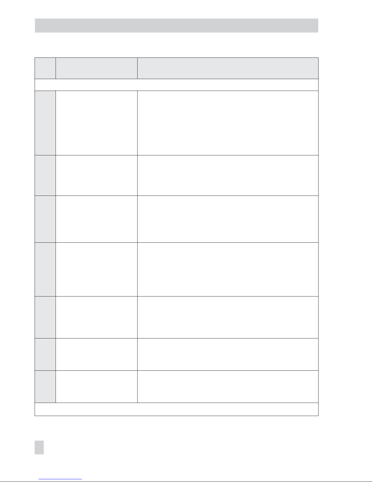
Code
no.
Parameter – Display, values
[default setting]
Description
Note: Codes with marked with an asterisk (*) must be enabled with Code 3 prior to configuration.
21*
Required transit time OPEN
(w ramp open)
0 to 240 s [0]
ESC
The time required to pass through the operating range when the
valve opens.
Limitation of the transit time (Code 21 and 22):
For some applications it is better to limit the actuating speed of
the actuator to prevent it from engaging too fast in the running
process.
Code 21 has priority over Code 15.
22*
Required transit time
CLOSED (w ramp closed)
0 to 240 s [0]
ESC
The time required to pass through the operating range when the
valve closes.
Code 22 has priority over Code 14.
23*
Total valve travel
0 to 99 · 107[0]
Exponential reading from 9999 travel
cycles onwards
RES · ESC
Totaled double valve travel.
Can be reset to 0 via
RES.
Note: The number of travel cycles (in steps of 1000) is saved in a
non-volatile memory.
24*
Limit of total valve travel
1000 to 99 · 10
7
[1 000 000]
Exponential reading from 9999 travel
cycles onwards
ESC
Limit value of total valve travel. If the limit is exceeded, the fault
alarm and the wrench icons appear on the display.
34*
Closing direction
[CCL] Counterclockwise
CL Clockwise
ESC
Turning direction of the lever in which the valve is moved to the
CLOSED position (view onto the display of the positioner).
Needs only be entered in SUb initialization mode.
35*
Blocking position
[0] mm/° /%
ESC
Distance up to the CLOSED position (0 % position).
Only needs to be entered in SUb initialization mode.
36*
Reset
[OFF]
RUN · ESC
Resets all parameters to default settings.
Note: After setting
RUN, the positioner must be re-initialized.
64 EB 8387-5 EN
Code list
Page 65
Code
no.
Parameter – Display, values
[default setting]
Description
Note: Codes with marked with an asterisk (*) must be enabled with Code 3 prior to configuration.
39
System deviation e
–99.9 to 999.9 %
Deviation from the target position (e = w – x)
Display only
40
Minimum transit time OPEN
0 to 240 s [0]
Time [s] needed by the system (positioner, actuator and valve) to
move through the nominal travel/angle to open the valve (100 %
position).
Display only
41
Minimum transit time
CLOSED
0 to 240 s [0]
Time [s] needed by the system (positioner, actuator and valve) to
move through the nominal travel/angle to close the valve (0 %
position).
Display only
42
Auto-w/manual-w
0.0 to 100.0 % of the span
Supplied manual and automatic reference variable
Display only
43
Firmware version control
Xxxx
Positioner type and current firmware version (in alternating sequence)
Display only
44
y info
0 to 100 %, [0 %]
Control signal y [%] based on the travel range determined on initialization · Display only
MAX: The positioner builds up its maximum output pressure,
see description in Code 14 and 15.
0 P: The positioner vents completely, see description in
Code 14 and 15.
– – –: The positioner has not been initialized.
45
Forced venting status
YES · HIGH/LOW · NO
Indicates whether the option is installed or not · Display only
NO No forced venting installed
YES Forced venting installed
If a voltage supply is connected at the terminals of the forced
venting option, YES and HIGH appear on the display in alter
nating sequence. If a voltage supply is not applied (actuator
vented, fail-safe position indicated on the display by the S icon),
YES and LOW appear on the display in alternating sequence.
46*
Bus address
ESC
Display only
EB 8387-5 EN 65
Code list
Page 66
Code
no.
Parameter – Display, values
[default setting]
Description
Note: Codes with marked with an asterisk (*) must be enabled with Code 3 prior to configuration.
47*
Status of write protection
switch
[NO]
YES · ESC
When the write protection function is activated, device data can
only be read, but not overwritten over FF communication.
48*
Diagnostics
Diagnostic parameters d
d0 Temperature
–55 to 125 °C
Current operating temperature [°C] inside the positioner
(accuracy±3 %)
Display only
d1 Minimum temperature
[20]
The lowest temperature below 20 °C that has ever occurred.
Display only
d2 Maximum temperature
[20]
The highest temperature above 20 °C that has ever occurred.
Display only
d3 Number of zero
calibrations
[0]
The number of zero calibrations since the last initialization.
Display only
d4 Number of
initializations
[0]
The number of initializations that have been performed since the
last reset.
Display only
d5 Zero point limit
[5 %]
0.0 to 100.0 % of the
nominal range
User-defined zero point monitoring
Used for error monitoring of the zero point shift.
d6 Condensed state Condensed state, made up from the individual states · Display
only
OK Okay
C Maintenance required
CR Maintenance demanded
B Maintenance alarm
I Function check
66 EB 8387-5 EN
Code list
Page 67
Code
no.
Parameter – Display, values
[default setting]
Description
Note: Codes with marked with an asterisk (*) must be enabled with Code 3 prior to configuration.
48*
d7 Start reference test
[OFF]
ON · ESC
Starting of a reference test (for the EXPERT+functions: Drive
signal y steady-state (d1) and drive signal y hysteresis (d2).
The reference test can only be activated in manual operating
mode as the valve moves through its entire working range.
If EXPERT+is activated at later point in time, the reference graphs
must be plotted in order to activate the diagnostic functions.
d8 EXPERT
+
activation Enter the activation code for EXPERT+.
After the activation procedure has been successfully completed,
YES appears under d8.
FF parameters
F0 Firmware Rev.
Communication
Display only
F1 Binary input Display only
1 Active · 2 Inactive
F3 Simulate PV Activation of simulation mode
Positioner (AO)
A0 Target Mode Target operating mode
A1 Actual Mode Actual operating mode · Display only
A2 CAS_IN Value Analog reference variable adopted from an upstream function
block (value) · Display only
A3 CAS_IN Status Analog reference variable adopted from an upstream function
block (status) · Display only
A4 SP Value Reference variable w (value) · Display only
A5 SP Status Reference variable w (status) · Display only
A6 OUT Value Manipulated variable (value) · Display only
A7 OUT Status Manipulated variable (status) · Display only
A8 BLOCK ERR Active block error · Display only
EB 8387-5 EN 67
Code list
Page 68
Code
no.
Parameter – Display, values
[default setting]
Description
Note: Codes with marked with an asterisk (*) must be enabled with Code 3 prior to configuration.
48*
Process controller (PID)
P0 Target Mode Target operating mode
P1 Actual Mode Actual operating mode · Display only
P2 CAS_IN Value Analog reference variable adopted from an upstream function
block (value) · Display only
P3 CAS_IN Status Analog reference variable adopted from an upstream function
block (status) · Display only
P4 SP Value Reference variable w (value) · Display only
P5 SP Status Reference variable w (status) · Display only
P6 OUT Value Manipulated variable (value) · Display only
P7 OUT Status Manipulated variable (status) · Display only
P8 BLOCK ERR Active block error · Display only
Positioner (AO TRD), binary input (DI1 TRD, DI2 TRD)
t0 Target Mode (AO TRD) Target operating mode
t1 Actual Mode (AO TRD) Actual operating mode · Display only
t2 Transducer State State of the Transducer Block · Display only
t3 BLOCK ERR AO TRD Active block error · Display only
t4 Target Mode (DI1 TRD) Target operating mode
t5 Actual Mode (DI1 TRD) Actual operating mode · Display only
t6 BLOCK ERR DI1 TRD Active block error · Display only
t7 Target Mode (DI2 TRD) Target operating mode
t8 Actual Mode (DI2 TRD) Actual operating mode · Display only
t9 BLOCK ERR DI2 Active block error · Display only
68 EB 8387-5 EN
Code list
Page 69
Code
no.
Parameter – Display, values
[default setting]
Description
Note: Codes with marked with an asterisk (*) must be enabled with Code 3 prior to configuration.
48*
Operating unit (RES)
S0 Target Mode (RES) Target operating mode
S1 Actual Mode (RES) Actual operating mode · Display only
S2 BLOCK ERR (RES) Active block error · Display only
Binary input (DI1)
I0 Target Mode (DI1) Target operating mode
I1 Actual Mode (DI1) Actual operating mode · Display only
I2 Field_Val_D Value Discrete process variable field hardware (value) · Display only
I3 Field_Val_D Status Discrete process variable field hardware (status) · Display only
I4 OUT_D Value Discrete output variable (value) · Display only
I5 OUT_D Status Discrete output variable (status) · Display only
I6 BLOCK ERR Active block error · Display only
Binary input DI2
L0 Target Mode (DI2) Target operating mode
L1 Actual Mode (DI2) Actual operating mode · Display only
L2 Field_Val_D Value Discrete process variable field hardware (value) · Display only
L3 Field_Val_D Status Discrete process variable field hardware (status) · Display only
L4 OUT_D Value Discrete output variable (value) · Display only
L5 OUT_D Status Discrete output variable (status) · Display only
L6 BLOCK ERR Active block error · Display only
D2 Function Block L
L0 Target Mode DI2 Required operating mode
L1 Actual Mode DI2 Actual operating mode
L2 Field_Val_D Value Displays the discrete input variable
EB 8387-5 EN 69
Code list
Page 70
Code
no.
Parameter – Display, values
[default setting]
Description
Note: Codes with marked with an asterisk (*) must be enabled with Code 3 prior to configuration.
48*
L3 Field_Val_D Status and its status
L4 OUT_D Value Displays the discrete output variable
L5 OUT_D Status and its status
L6 BLOCK ERR Displays the current block error
49*
PST Description of partial stroke test function (refer to EB 8388-5 EN)
Note: The error codes listed in following appear in the display corresponding to their status
classification set over the condensed state (Maintenance required/Maintenance demanded:
, Maintenance alarm: ). If “No message” is assigned to the error code as the status
classification, the error is not included in the condensed state.
A status classification is assigned to every error code in the default setting. The status classification of error codes can also be changed as required using an operating software (e.g.
TROVIS-VIEW). Refer to the Configuration Manual KH 8387-5.
70 EB 8387-5 EN
Code list
Page 71
Initialization errors
Error codes – Recommended action Condensed state alarm active, when prompted, Err appears.
When fault alarms exist, they are displayed here.
50
x > range The value supplied by the measuring signal is either too high or
too low, the measuring sensor is close to its mechanical limit.
• Pin positioned incorrectly.
• Bracket slipped in case of NAMUR attachment or positioner is
not central.
• Follower plate incorrectly attached.
Status classification [Maintenance required]
Recommended action Check attachment and pin position, set operating mode from
SAFE to MAN and re-initialize the positioner.
51
∆
x < range The measuring span of the sensor is too low.
• Pin positioned incorrectly.
• Wrong lever.
A rotational angle smaller than 16° at the positioner shaft creates
just an alarm. An angle below 9° leads to the initialization being
canceled.
Status classification [Maintenance required]
Recommended action Check attachment and re-initialize the positioner.
52
Attachment • Positioner attachment incorrect.
• Nominal travel/angle (Code 5) could not be achieved on
initialization under NOM or SUb (no tolerance downwards
permissible).
• Mechanical or pneumatic fault, e.g. wrong lever selected or
supply pressure too low to move to the required position.
Status classification [Maintenance required]
Recommended action Check attachment and supply pressure. Re-initialize the
positioner.
Under certain circumstances, it may be possible to check the
maximum travel/angle by entering the actual pin position and
then performing an initialization under MAX.
After initialization has been completed, the Code 5 indicates the
maximum achieved travel or angle.
EB 8387-5 EN 71
Code list
Page 72
Error codes – Recommended action Condensed state alarm active, when prompted, Err appears.
When fault alarms exist, they are displayed here.
53
Initialization time exceeded
(Init time >)
The initialization routine lasts too long. The positioner returns to
its previous operating mode.
• No pressure on the supply line or there is a leak.
• Supply air failure during initialization.
Status classification [Maintenance required]
Recommended action Check attachment and supply pressure.
Re-initialize the positioner.
54
Initialization/forced venting 1) A solenoid valve is installed (Code 45 = YES) and was
not or not properly connected so that an actuator pressure
could not be built up. The alarm is generated when you
attempt to initialize the positioner.
2) If you attempt to initialize the device from the fail-safe
position (SAFE).
Status classification [Maintenance required]
Recommended action Re. 1) Check connection and supply voltage of the forced venting
Code 45 HIGH/LOW
Re. 2) Set the MAN operating mode over Code 0. Then initialize
the positioner.
55
Transit time too short
(transit time <)
The actuator positioning rates determined during the initialization are so short that the positioner cannot adapt itself optimally.
Status classification [Maintenance required]
Recommended action Check the volume restriction setting as described in section 4,
re-initialize the positioner.
56
Pin position Initialization was canceled because you are required to enter the
pin position for the selected initialization modes NOM and SUb.
Status classification [Maintenance required]
Recommended action Enter pin position over Code 4 and nominal travel/angle over
Code 5. Re-initialize the positioner.
72 EB 8387-5 EN
Code list
Page 73
Operational errors
Error codes – Recommended action Condensed state alarm active, when prompted, Err appears.
When fault alarms exist, they are displayed here.
57
Control loop Control loop error, the control valve does not react within the to
lerable times of the controlled variable (tolerance band alarm
Code 19).
• Actuator mechanically blocked.
• Attachment of the positioner subsequently shifted.
• Supply pressure not sufficient.
Status classification [Maintenance required]
Recommended action Check attachment.
58
Zero point Zero point incorrect.
Error may arise when the mounting position/linkage of the posi
tioner moves or when the valve seat trim is worn, especially with
soft-sealed plugs.
Status classification [Maintenance required]
Recommended action Check valve and mounting of the positioner. If OK, perform a
zero calibration over Code 6 (see section 7.6 on page 52).
If the lever position on the back of the positioner has been
changed (e.g. while exchanging the lever), move the lever as far
as it will go in both directions to adapt it to the internal measuring lever.
We recommend re-initializing the positioner if the zero point de
-
viates by more than 5 %.
59
Autocorrection Should an error occur in the data range of the positioner, the
self-monitoring function recognizes it and automatically corrects
it.
Status classification [No message]
Recommended action Automatic
60
Fatal error An error was detected in the data relevant for safety,
autocorrection is not possible. This may be due to EMC
disturbances.
The control valve moves to its fail-safe position.
Status classification Maintenance alarm (cannot be classified)
Recommended action Reset over Code 36.
Re-initialize the positioner (see sections 7.7 and 7.5).
EB 8387-5 EN 73
Code list
Page 74
Hardware errors
Error codes – Recommended action Condensed state alarm active, when prompted, Err appears.
When fault alarms exist, they are displayed here.
62
x signal Determination of the measured data for the actuator has failed.
Conductive plastic element is defective.
The positioner continues to run in emergency mode, but should
be replaced as soon as possible.
The emergency mode on the display is indicated by a blinking
closed-loop control icon and 4 dashes instead of the position in
-
dication.
Note on the control:
If the measuring system has failed, the positioner is still in a reli
able state. The positioner switches to emergency mode where the
position cannot be accurately controlled anymore. However, the
positioner continues operation according to its reference variable
signal so that the process remains in a safe state.
Status classification [Maintenance required]
Recommended action Return the positioner to SAMSON AG for repair.
64
i/p converter The circuit of the i/p converter has been interrupted.
Status classification Maintenance alarm (cannot be classified)
Recommended action Cannot be remedied.
Return the positioner to SAMSON AG for repair.
65
Hardware A hardware error has occurred, the positioner moves to the
fail-safe position SAFE.
Status classification Maintenance alarm (cannot be classified)
Recommended action Confirm error and return to the automatic operating mode, or
perform a reset and re-initialize the device. If this is not success
ful, return device to SAMSON AG for repair.
66
Data memory The writing of data to the data memory does not work anymore,
e.g. when the written data deviate from the read data.
Valve moves to the fail-safe position.
Status classification Maintenance alarm (cannot be classified)
Recommended action Return the positioner to SAMSON AG for repair.
74 EB 8387-5 EN
Code list
Page 75
Error codes – Recommended action Condensed state alarm active, when prompted, Err appears.
When fault alarms exist, they are displayed here.
67
Test calculation The hardware controller is monitored by means of a test
calculation.
Status classification Maintenance alarm (cannot be classified)
Recommended action Confirm error. If this is not possible, return the positioner to
SAMSON AG for repair.
Data errors
Error codes – Recommended action Condensed state alarm active, when prompted, Err appears.
When fault alarms exist, they are displayed here.
68
Control parameter Control parameter error
Status classification [Maintenance required]
Recommended action Confirm error, perform reset and re-initialize the positioner.
69
Poti parameter Parameter error of the digital potentiometer.
Status classification [Maintenance required]
Recommended action Confirm error, perform reset and re-initialize the positioner.
70
Calibration Error in the production calibration data. Subsequently, the device
runs on default values.
Status classification [Maintenance required]
Recommended action Return the positioner to SAMSON AG for repair.
71
General parameters Parameter errors that are not critical for the control.
Status classification [Maintenance required]
Recommended action Confirm error.
Check and, if necessary, reset required parameters.
72
Start-up parameters Start-up parameter error
Status classification [Maintenance required]
Recommended action Confirm error, perform reset and re-initialize the positioner.
EB 8387-5 EN 75
Code list
Page 76
Error codes – Recommended action Condensed state alarm active, when prompted, Err appears.
When fault alarms exist, they are displayed here.
73
Internal device error 1 Internal device error
Status classification [Maintenance required]
Recommended action Return the positioner to SAMSON AG for repair.
74
FF parameters Parameter errors that are not critical for the control.
Status classification [Maintenance required]
Recommended action Confirm error and perform reset.
75
Info parameters Info parameter errors that are not critical for the control.
Status classification [Maintenance required]
Recommended action Confirm error.
Check and, if necessary, reset required parameters.
76
No emergency mode The travel measuring system of the positioner has a
self-monitoring function (see Code 62).
An emergency mode (open-loop control) is not available for
certain actuators, such as double-acting actuators. In this case,
the positioner moves to the fail-safe position when a measuring
error occurs. During the initialization, the positioner checks
whether the actuator has such a function or not.
Status classification [No message]
Recommended action Merely information, confirm, if necessary.
No further action necessary.
77
Program loading error
Additional alarm at the fault
alarm contact
When the positioner starts operation for the first time after the in
-
put signal has been applied, it carries out a self-test (
tEStinG runs
across the display).
If the positioner loads the wrong program, the valve moves to the
fail-safe position. It is not possible to make the valve leave this
fail-safe position again.
Status classification
Maintenance alarm (cannot be classified)
Recommended action Interrupt current and restart positioner.
Otherwise, return the positioner to SAMSON AG for repair.
78
Options parameter Errors in options parameters
Status classification [Maintenance required]
Recommended action Return the positioner to SAMSON AG for repair.
76 EB 8387-5 EN
Code list
Page 77
Diagnosis errors
Error codes – Recommended action Condensed state alarm active, when prompted, Err appears.
When fault alarms exist, they are displayed here.
79
Extended diagnostics Error messages are generated in the extended EXPERT+diagnos
-
tics if EXPERT+has been successfully activated in Code 48.
Status classification
Maintenance required (cannot be classified)
80
Diagnostic parameters Errors that are not critical for control.
Status classification Maintenance required (cannot be classified)
81
Reference test canceled The reference graphs were not plotted or an error occurred
during plotting the reference graphs for drive signal y
steady-state or drive signal y hysteresis.
• Reference test was interrupted
• Reference line y steady-state or y hysteresis was not adopted.
Error messages are saved in EEPROM. They cannot be reset.
Status classification [Maintenance required]
Recommended action Check and, if necessary, perform a new reference test
EB 8387-5 EN 77
Code list
Page 78
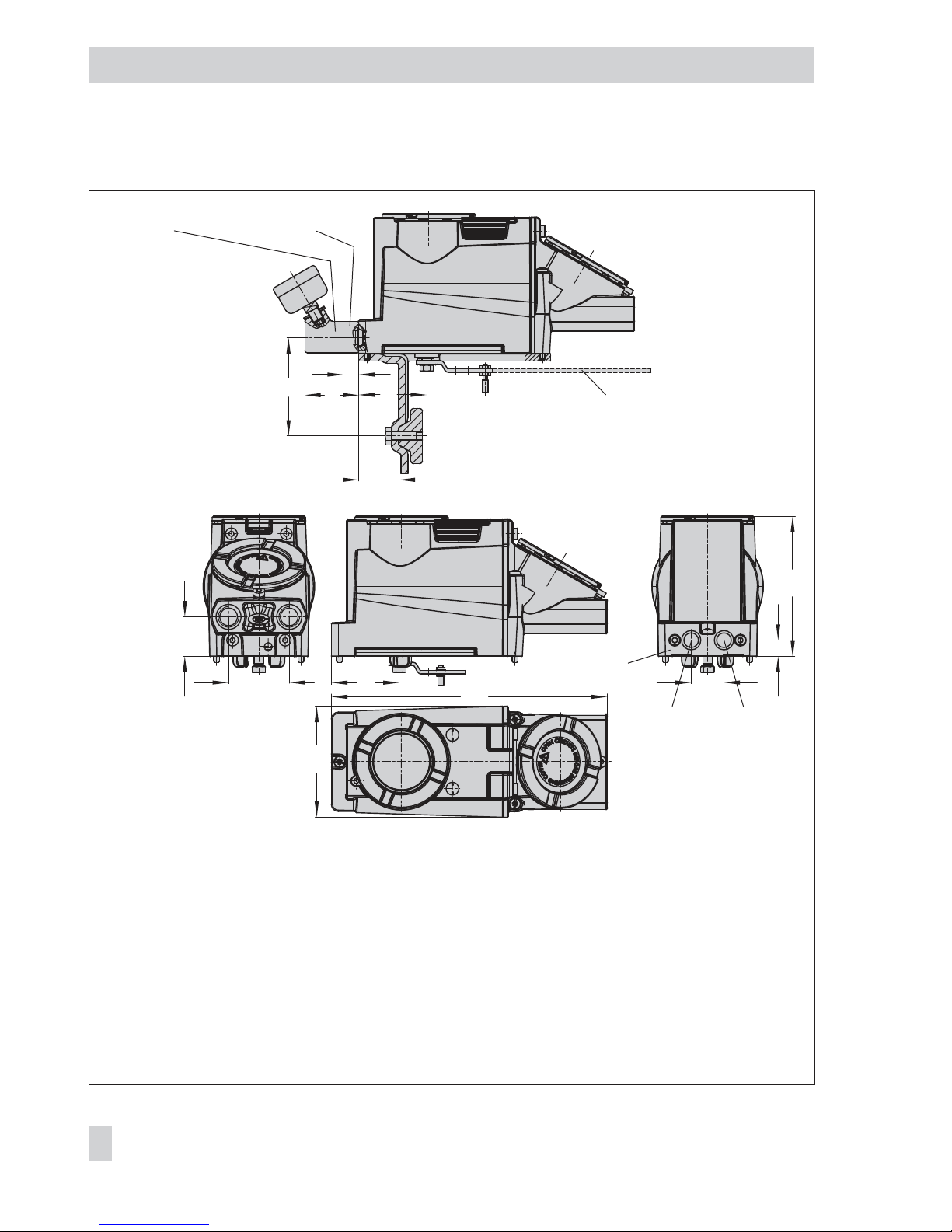
12 Dimensions in mm
78 EB 8387-5 EN
Dimensions in mm
70
15
46
34
14
122
95
34
53
28
NPT ½, ¼
58
58
236
Output Supply
Fig. 15a · Attachment according to IEC 60534-6 and direct attachment
Attachment acc. to
IEC 60534-6
→
Direct
attachment
→
Pressure
gauge
bracket
or connecting plate
(G ¼ only)
Electrical connections:
2 x female thread
½ NPT or
M20 x 1.5
Lever in mm
S = 17
M = 50
L = 100
XL = 200
¼ NPT
Page 79
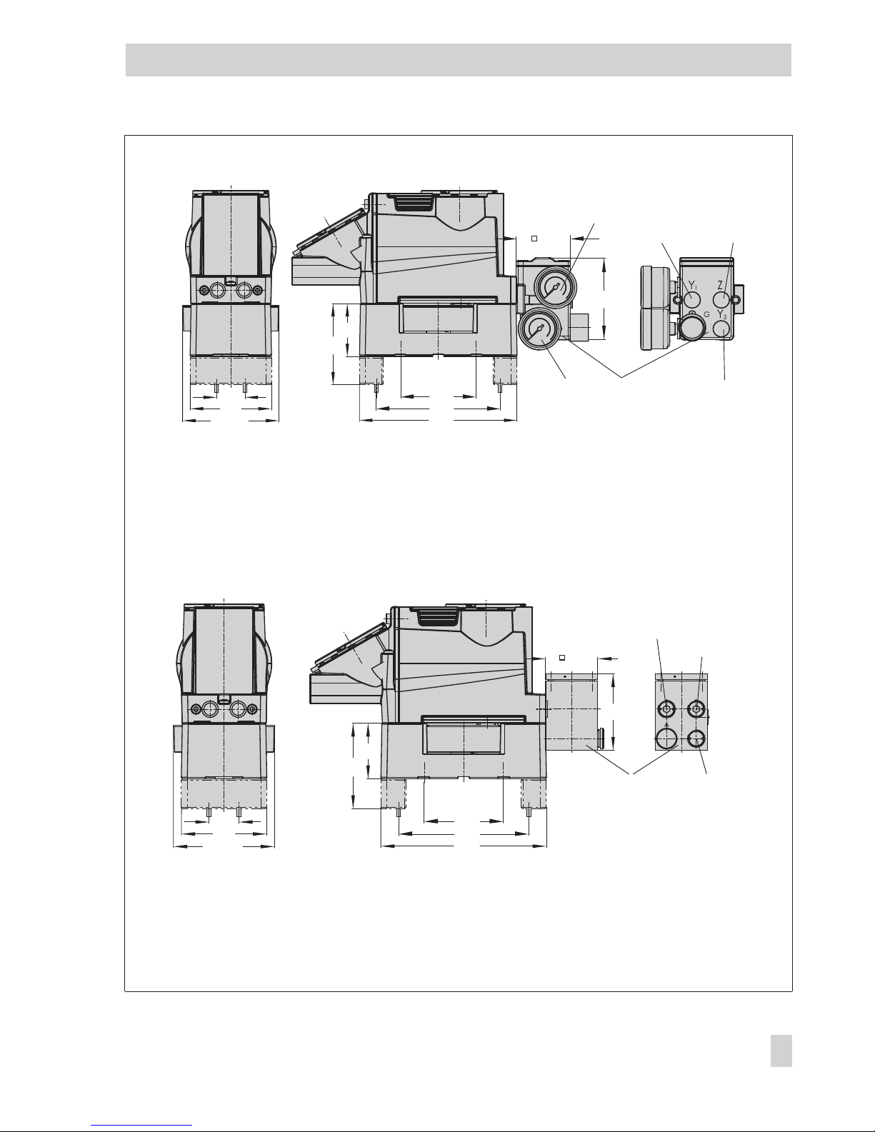
EB 8387-5 EN 79
Dimensions in mm
80
52
Output Y
1
Output Y
2
Supply (9)
Output Y
1
Output Y
2
56
86
130
80
166
30
86
Ø 101
Fig. 15b · Attachment to rotary actuators VDI/VDE 3845 (Sept. 2010), level 1, size AA1 to AA4
Type 3710
Reversing
Amplifier
(option)
A1Z
A
2
56
86
130
80
166
30
86
Ø 101
76
50
Output A2
Output A1
Supply (9)
Reversing amplifier
1079-1118 or
1079-1119
(option)
Page 80
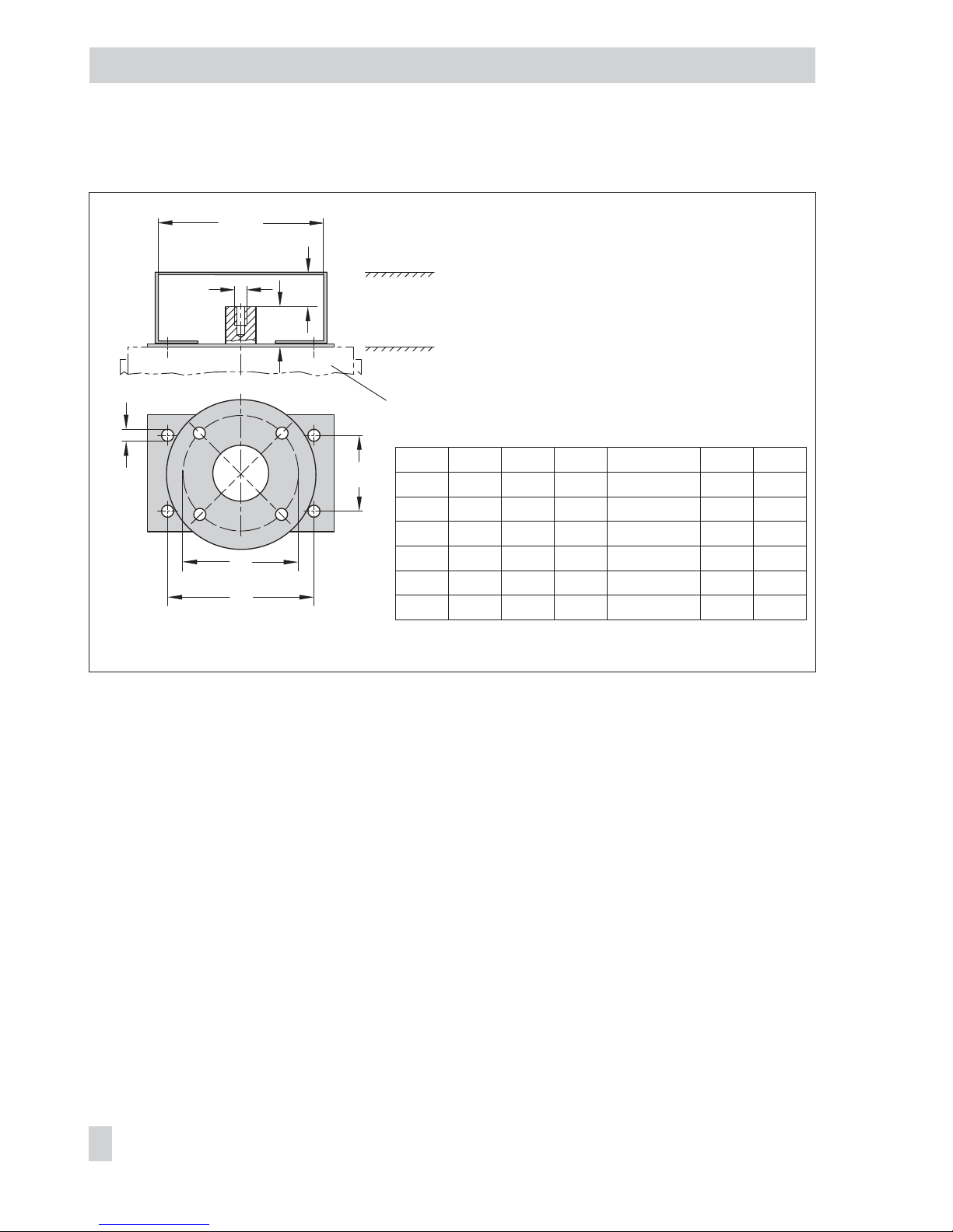
12.1 Fixing levels according to VDI/VDE 3845 (September 2010)
80 EB 8387-5 EN
Dimensions in mm
A
M6
C
B
25
M
min
Ød
ØD
Level 2 (bracket surface)
Level 1 (actuator surface)
Actuator
Dimensions in mm
Size A B C
∅
d M
min
∅
D*
AA0 50 25 15 5.5 for M5 66 50
AA1 80 30 20 5.5 for M5 96 50
AA2 80 30 30 5.5 for M5 96 50
AA3 130 30 30 5.5 for M5 146 50
AA4 130 30 50 5.5 for M5 146 50
AA5 200 50 80 6.5 for M6 220 50
* Flange type F05 according to DIN EN ISO 5211
Page 81

EB 8387-5 EN 81
Page 82
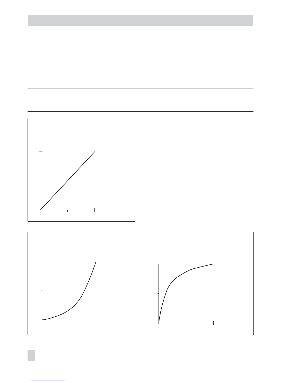
13 Appendix
13.1 Selecting the valve characteristic
The characteristics that can be selected in Code 20 are shown in following in graph form.
Note: A characteristic can only be defined (user-defined characteristic) using a workstation/
operating software (e.g. TROVIS-VIEW).
Linear (select characteristic: 0)
Equal percentage (select characteristic: 1) Rev. equal percentage (select characteristic: 2)
82 EB 8387-5 EN
Appendix
0
50
100
0 50 100
Travel/ angle of rotation [%]
Reference variable [%]
0
50
100
0 50 100
Travel/ angle of rotation [%]
Reference variable [%]
0
50
100
0 50 100
Travel/ angle of rotation [%]
Reference variable [%]
Page 83
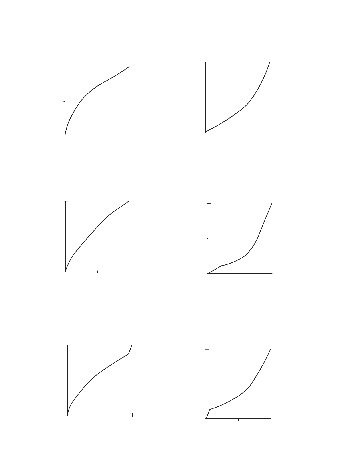
SAMSON butterfly valve linear
(select characteristic: 3)
SAMSON butterfly valve equal percentage
(select characteristic: 4)
VETEC rotary plug valve linear
(select characteristic: 5)
VETEC rotary plug valve equal percentage
(select characteristic: 6)
Segmented valve ball linear
(select characteristic: 7)
Segmented ball valve equal percentage
(select characteristic: 8)
0
50
100
0 50 100
Travel/ angle of rotation [%]
Reference variable [%]
0
50
100
0 50 100
Travel/ angle of rotation [%]
Reference variable [%]
0
50
100
0 50 100
Travel/ angle of rotation [%]
Reference variable [%]
0
50
100
0 50 100
Travel/ angle of rotation [%]
Reference variable [%]
0
50
100
0 50 100
Travel/ angle of rotation [%]
Reference variable [%]
0
50
100
0 50 100
Travel/ angle of rotation [%]
Reference variable [%]
Page 84
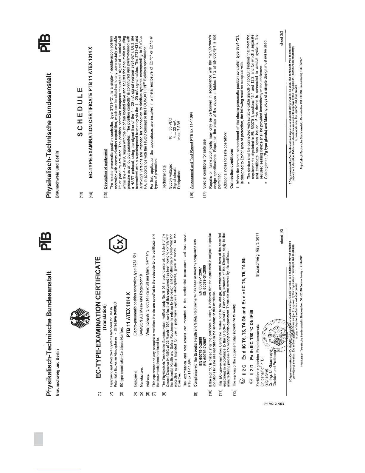
84 EB 8387-5 EN
Page 85
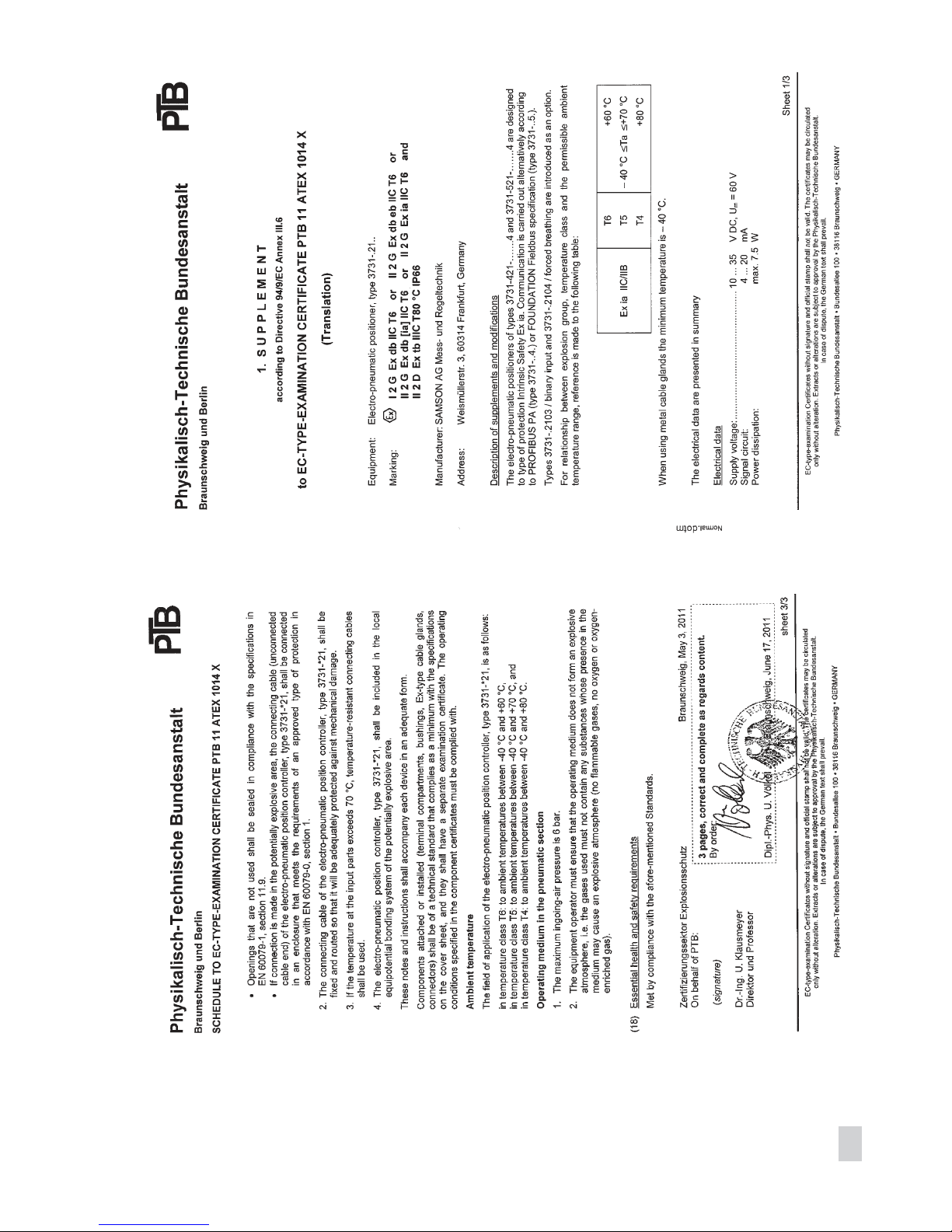
EB 8387-5 EN 85
Page 86
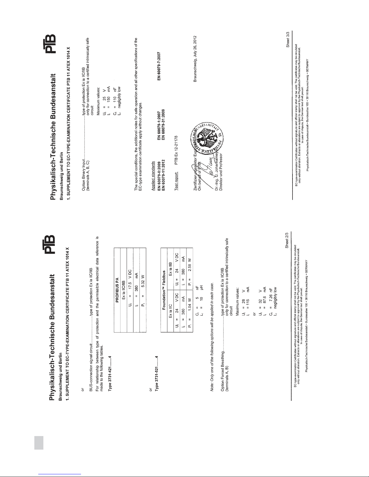
86 EB 8387-5 EN
Page 87
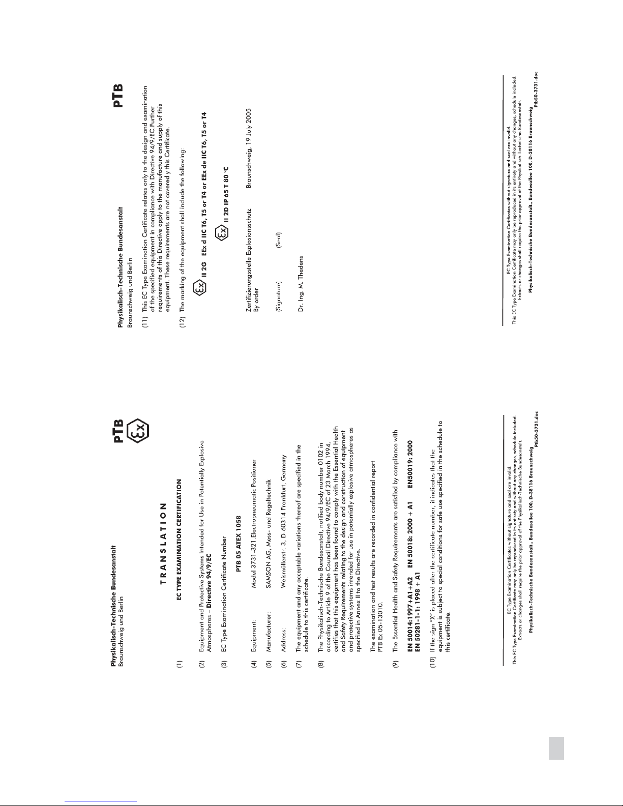
EB 8387-5 EN 87
Page 88
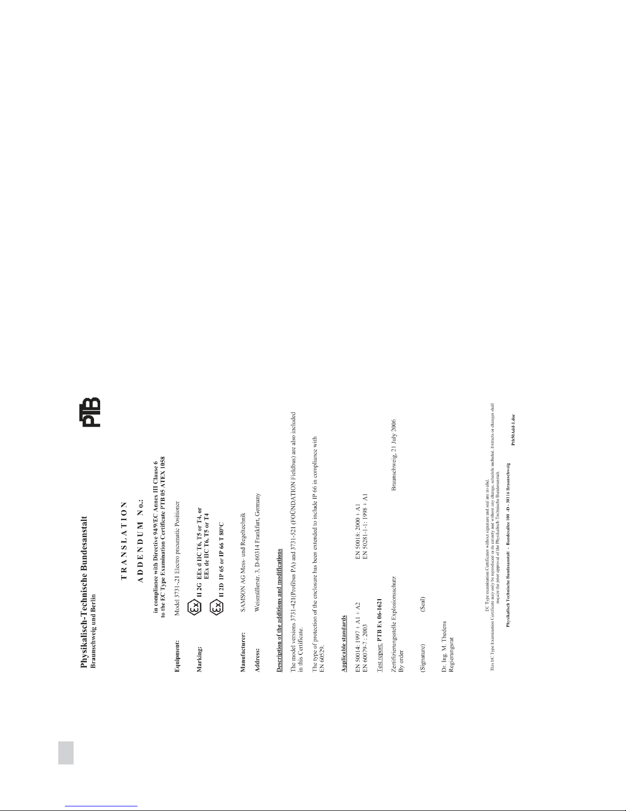
88 EB 8387-5 EN
Page 89
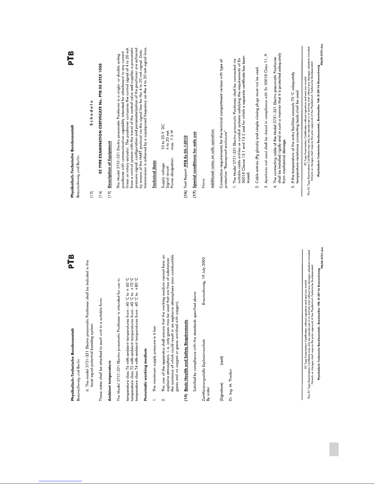
EB 8387-5 EN 89
Page 90

Index
A
Accessories . . . . . . . . . . . . . . . . . . 28 - 29
Additional equipment
binary input. . . . . . . . . . . . . . . . . . . . 9
electrical connection . . . . . . 36
technical data . . . . . . . . . 12
extended EXPERT+ valve diagnostics . . 9
forced venting . . . . . . . . . . . . . . . . . . 9
electrical connection . . . . . . 36
technical data . . . . . . . . . 12
Article code . . . . . . . . . . . . . . . . . . . . . . 7
Attachment
acc. to IEC 60534-6 (NAMUR). . . . . 20
direct attachment
to Type 3277 Actuator . . . . . 18
to Type 3277-5 Actuator . . . . 15
reversing amplifier. . . . . . . . . . . . . . 26
to rotary actuators . . . . . . . . . . . . . . 24
to Type 3510 Micro-flow Valve. . . . . 22
B
Bar elements . . . . . . . . . . . . . . . . . . . . . 38
Blocking position
canceling . . . . . . . . . . . . . . . . . . . . 51
Bus line. . . . . . . . . . . . . . . . . . . . . . . . . 36
C
Cable entry. . . . . . . . . . . . . . . . . . . . . . 35
Characteristic
selecting . . . . . . . . . . . . . . . . . . 63, 82
Code list . . . . . . . . . . . . . . . . . . . . 59 - 77
Communication . . . . . . . . . . . . . . . 10 - 11
Configuration
using NI-BUS Configurator . . . . . . . . 10
using TROVIS-VIEW. . . . . . . . . . . . . 10
Connections
electrical . . . . . . . . . . . . . . . . . . . . . 33
pneumatic . . . . . . . . . . . . . . . . . . . . 31
D
Default values . . . . . . . . . . . . . . . . . . . . 53
Design, positioner . . . . . . . . . . . . . . . . . . 8
Display . . . . . . . . . . . . . . . . . . . . . 38 - 39
turned by 180° . . . . . . . . . . . . . . . . 40
E
Electrical connections. . . . . . . . . . . . . . . 33
Enable configuration . . . . . . . . . . . . 38, 54
Error messages
confirming. . . . . . . . . . . . . . . . . . . . 57
data errors . . . . . . . . . . . . . . . . . . . 75
diagnosis errors. . . . . . . . . . . . . . . . 77
initialization errors. . . . . . . . . . . . . . 71
operational errors . . . . . . . . . . . . . . 73
Explosion protection . . . . . . . . . . . . . . . 12
F
Fail-safe position. . . . . . . . . . . . . . . . . . 56
determining. . . . . . . . . . . . . . . . . . . 42
I
Initialization
MAN manually selected range . . 43, 47
MAX maximum range. . . . . . . . 43 - 44
NOM nominal range . . . . . . . . . 43, 45
SUB substitute calibration . . . . . . 43, 48
M
Maintenance. . . . . . . . . . . . . . . . . . . . . 58
Malfunction. . . . . . . . . . . . . . . . . . . . . . 56
Mounting parts . . . . . . . . . . . . . . . 28 - 29
90 EB 8387-5 EN
Index
Page 91

O
Operating modes . . . . . . . . . . . . . . 38, 55
Operating range
checking . . . . . . . . . . . . . . . . . . . . . 41
MAN manually selected range . . 43, 47
MAX maximum range. . . . . . . . 43 - 44
NOM nominal range . . . . . . . . . 43, 45
Operation . . . . . . . . . . . . . . . . . . . 54 - 57
Operator controls . . . . . . . . . . . . . . . . . 39
P
Pneumatic connections. . . . . . . . . . . . . . 31
Principle of operation, positioner . . . . . . . 8
R
Reset . . . . . . . . . . . . . . . . . . . . . . . . . . 53
Reversing amplifier . . . . . . . . . . . . . . . . 26
Rotary pushbutton . . . . . . . . . . . . . . . . . 38
S
Serial interface . . . . . . . . . . . . . . . . . . . 38
Signal pressure . . . . . . . . . . . . . . . . . . . 32
limiting . . . . . . . . . . . . . . . . . . . . . . 40
Start-up . . . . . . . . . . . . . . . . . . . . . 40, 53
Status messages . . . . . . . . . . . . . . . . . . 38
Function check. . . . . . . . . . . . . . . . . 57
Maintenance alarm . . . . . . . . . . . . . 56
Maintenance demanded. . . . . . . . . . 56
Maintenance required . . . . . . . . . . . 56
Substitute calibration . . . . . . . . . . . . 43, 48
Supply pressure. . . . . . . . . . . . . . . . . . . 32
T
Technical data. . . . . . . . . . . . . . . . . . . . 11
Travel tables . . . . . . . . . . . . . . . . . . . . . 14
V
Valve characteristic, selecting. . . . . . . . . 82
Z
Zero calibration . . . . . . . . . . . . . . . . . . 52
EB 8387-5 EN 91
Index
Page 92

SAMSON AG · MESS- UND REGELTECHNIK
Weismüllerstraße 3 · 60314 Frankfurt am Main, Germany
Phone: +49 69 4009-0 · Fax: +49 69 4009-1507
Internet: http://www.samson.de EB 8387-5 EN
2016-04
 Loading...