

Samson Airline AX1, AL1 P, Airline AM1, Airline AL1 Owner's Manual
UHF Wireless System
Owners Manual
Handheld Transmitter
Presentation
Transmitter
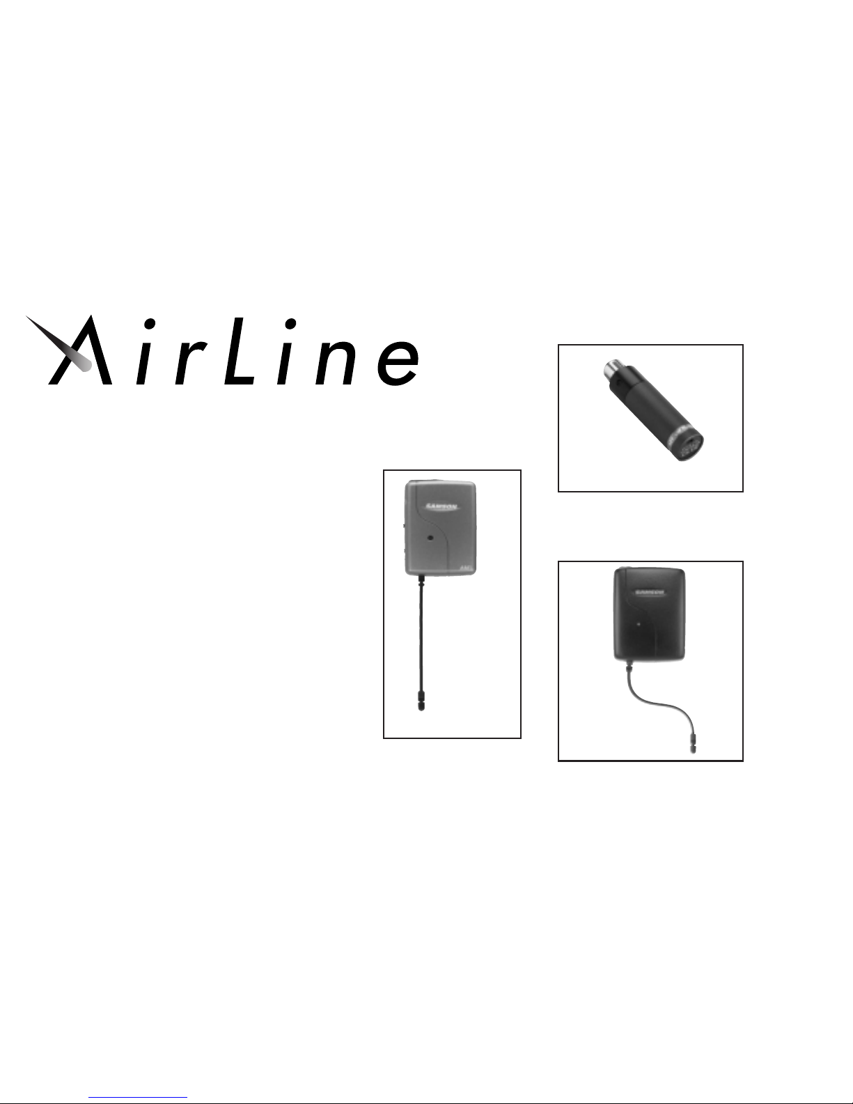
• AX1 Handheld Transmitter
• AL1 Presentation Transmitter
• AM1 Receiver
SAMSON
AM1 Receiver

ENGLISH
Introduction 1
QuickStart 2
Guided Tour - AM1 Receiver 4
Guided Tour - AX1 Handheld Transmitter 6
Guided Tour - AL1 Presentation Transmitter 8
Setting Up and Using Your AirLine System 11
Attaching the Lanyard to the AL1 15
Specifications 69
Wiring Diagram 19
Channel Plan 71
FRANCAIS
Introduction 23
Prise en main 24
Tour d’horizon - Récepteur AM1 26
Tour d’horizon - Émetteur main AX1 28
Tour d’horizon - Émetteur de présentation AL1 30
Param étrage et utilisation du système AirLine 31
Fixation du cordon à L’AL1 37
Caractéristiques techniques 39
Schéma de câblage 41
Plan des canaux 42
DEUTSCH
Einleitung 45
Schnellstart 46
Führung - AM1 Empfänger 48
Führung - AX1 Aufsteck-Sender 50
Führung - AL1 Vario-Sender 52
AirLine-System einrichten und einsetzen 55
Halsgurt am AL1 befestigen 59
Technische Daten 61
Verdrahtungsplan 63
Kanalplan 64
ESPAÑOL
Introducción67
Guía rápida 68
Visita guiada - Receptor AM1 70
Visita guiada - Transmisor portátil AX1 72
Visita guiada - Transmisor para presentaciones AL1 74
Instalar y utilizar el sistema AirLine 77
Montar la correa en el AL1 81
Especificaciones 83
Esquema de cableado 85
Plano de canales 86
Table of Contents
Samson Technologies Corp. • 575 Underhill Blvd. • P.O. Box 9031 • Syosset, NY 11791-9031
Phone: 1-800-3-SAMSON (1-800-372-6766) • Fax: 516-364-3888
www.samsontech.com
Copyright 2001, Samson Technologies Corp.
Printed May 2001

Introduction
Samson AirLine
1
ENGLISH
Welcome to Samson AirLine—the wireless system for the new millennium! Wireless microphone and instrument systems were
originally developed to eliminate cables, providing unparalleled freedom of movement. AirLine takes this concept to a new level with
transmitters and receivers so small, lightweight and aerodynamic, they are nearly invisible, providing a completely “hassle-free” user
experience. To create the world’s smallest wireless systems, we developed new proprietary technology. Featuring miniaturized circuitry
and the ability to operate on a single tiny AAA battery (with 14 hours typical battery life), these systems also feature significantly
improved wireless reception and sound quality. What’s more, the AM1 micro receiver developed especially for the AirLine system is as
small as the AL1 transmitter.
There are two different Samson AirLine systems detailed in this manual. Both operate in the 801 - 805 MHz UHF frequency range
and each contains an AM1 micro receiver. The AirLine UHF Microphone System contains an AX1 hand-held transmitter, which plugs
into any standard wired dynamic microphone. The AirLine UHF Presentation System contains an AL1 presentation transmitter, which
contains a built-in electret condenser microphone and connection for an optional lavalier microphone.
In this manual, you’ll find a more detailed description of the features of all AirLine systems, as well as a guided tour through all components, step-by-step instructions for setting up your system and full specifications. If your AirLine system was purchased in the United
States, you’ll also find a warranty card enclosed—don’t forget to fill it out and mail it! This will enable you to receive online technical
support and will allow us to send you updated information about this and other Samson products in the future. If your AirLine system
was purchased outside of the U. S., contact your local distributor for warranty details. Also, be sure to check out our website
(http://www.samsontech.com) for complete information about our full product line.
SPECIAL NOTE for U.S. purchasers: Should your AirLine system ever require servicing, a
Return Authorization number (RA) is
necessary. Without this number, the unit will not be accepted. If your AirLine system was purchased in the United States, please call
Samson at 1-800-372-6766 for a Return Authorization number prior to shipping your system. If possible, return the unit in its original
carton and packing materials. If your AirLine system was purchased outside of the U. S., contact your local distributor for information.

Quick Start
Samson AirLine
2
ENGLISH
If you’ve had some prior experience using wireless systems, these QuickStart instructions will get you up and running with your
AirLine system in a matter of minutes! Detailed instructions for setting up and using your AirLine system can be found on page 11 of
this manual, and the “Guided Tour” sections on pages 4 - 16 provide full descriptions of all AirLine component controls and displays.
1. Make sure that the AM1 receiver and AX1 and/or AL1 transmitter are factory preset to the same channel.
2. Place a fresh battery in the AM1 receiver. Place the receiver where it will be used. The AM1 receiver can be mounted to the hot
shoe of the camera, clipped with the supplied clip or fastened by the use of the supplied velcro.
3. Set the power switch to your transmitter to the “off” position (away from the arrow) and place a fresh battery in it. Then turn the
transmitter back on momentarily; its LED will flash once and then go off if the battery is sufficiently strong. Once battery strength
is verified, turn the transmitter off.
4. If you are using an AX1, plug its XLR connector into a wired dynamic microphone; make a good tight connection, using the sup-
plied rubber gasket if necessary. If you are using the AL1 with an external lavalier microphone, make the physical connection
between its input connector and the microphone.
5. Make the physical cable connection between the AM1 receiver’s 2.5mm stereo output jack and audio input of your camera or
mixer using the supplied 2.5mm to 3.5mm SMM14 cable (see wiring diagram on page 19 for options).
6. Select the correct gain by using the MIC/LINE switch on the AM1 receiver to match the input of your camera or mixer.

Quick Start
Samson AirLine
3
ENGLISH
7. Turn on the receiver. The POWER/BATTERY LED will light momentarily indicating the power has been turned on.
8. Turn on your transmitter. The audio signal can be monitored through the 3.5mm stereo headphone output and headphone volume
can be adjusted via the headphone level trim pot with the supplied plastic screwdriver.
9. Turn on your camera or mixer but keep its volume all the way down. If your system contains an AL1 transmitter, make sure it is
unmuted. Set the Volume, Level or AF Level knob on the receiver fully clockwise; this is unity gain.
10. Speak or sing into your mic at a normal performance level while slowly raising the audio input control of your camera (if you
have one) or mixer until the desired level is reached. If necessary, use the supplied plastic screwdriver to adjust the transmitter’s
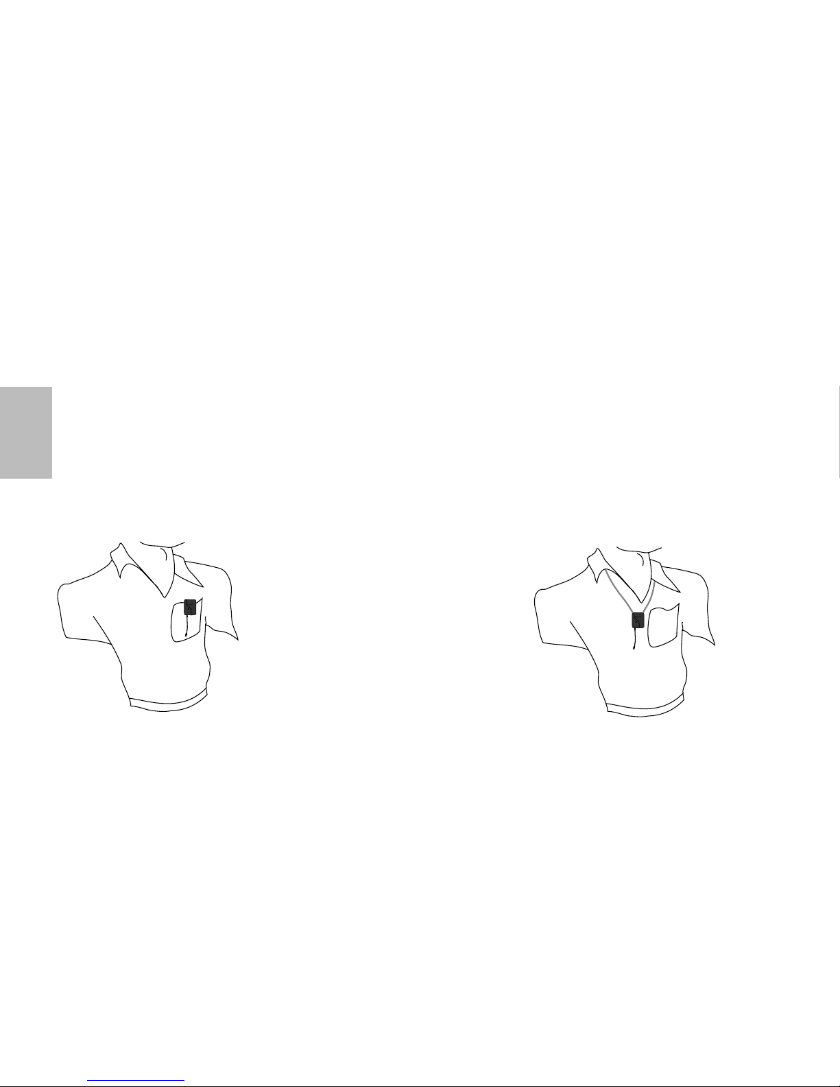
Gain trimpot in order to increase or decrease its signal level. If you are using an AL1 transmitter with the built-in microphone,
correct placement is critical to sound quality. It should be unobstructed by clothing and either clipped to a shirt pocket or lapel,
or worn around the neck on the supplied lanyard.
11. Do a walkaround through the intended area of coverage while monitoring the audio signal via the AM1 receiver headphone output or input level meter (if one is available).
Guided Tour - AM1 Receiver
Samson AirLine
4
ENGLISH
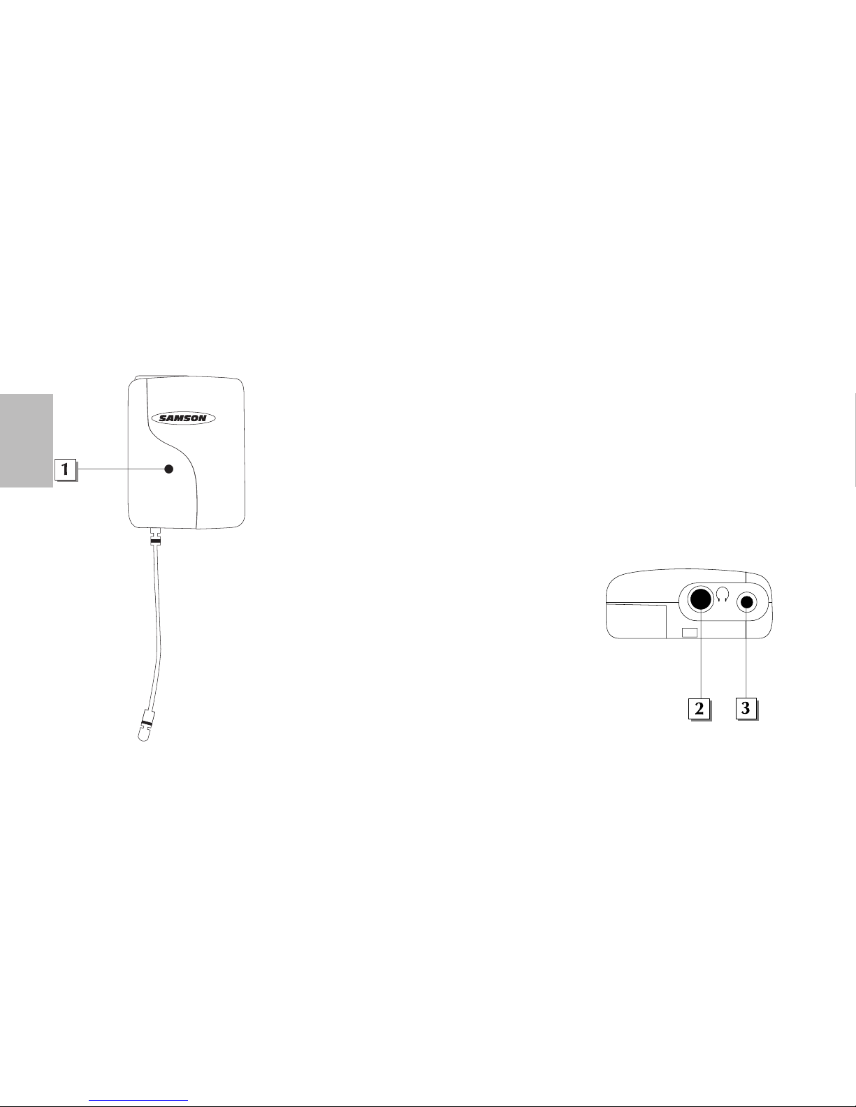
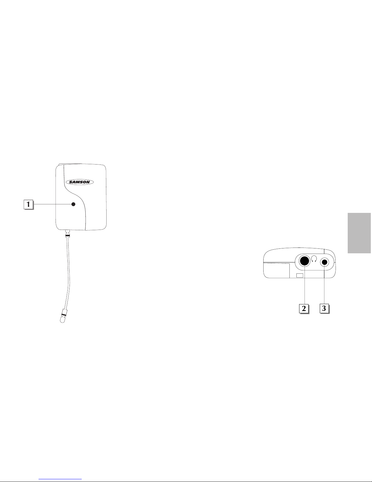
1: Multi-color LED - The LED will flash red momentarily when the power is switched on and a
charged battery is in place. It will light continuously red when battery is low and needs to be
replaced. When the AM1 is receiving RF the LED will light green. The LED will appear orange
when any combination of these events cause the LED to light green and red simultaneously.
2:
Headphone Output - This 3.5mm headphone level output jack can be used to monitor
audio signal.
3:
Audio Output - This 2.5mm jack will accept the supplied 2.5mm to 3.5mm stereo SMM14
cable and send the audio signal to the camera or mixer input (see #5 below to set the
correct output level; see wiring diagram on page 19 for options).
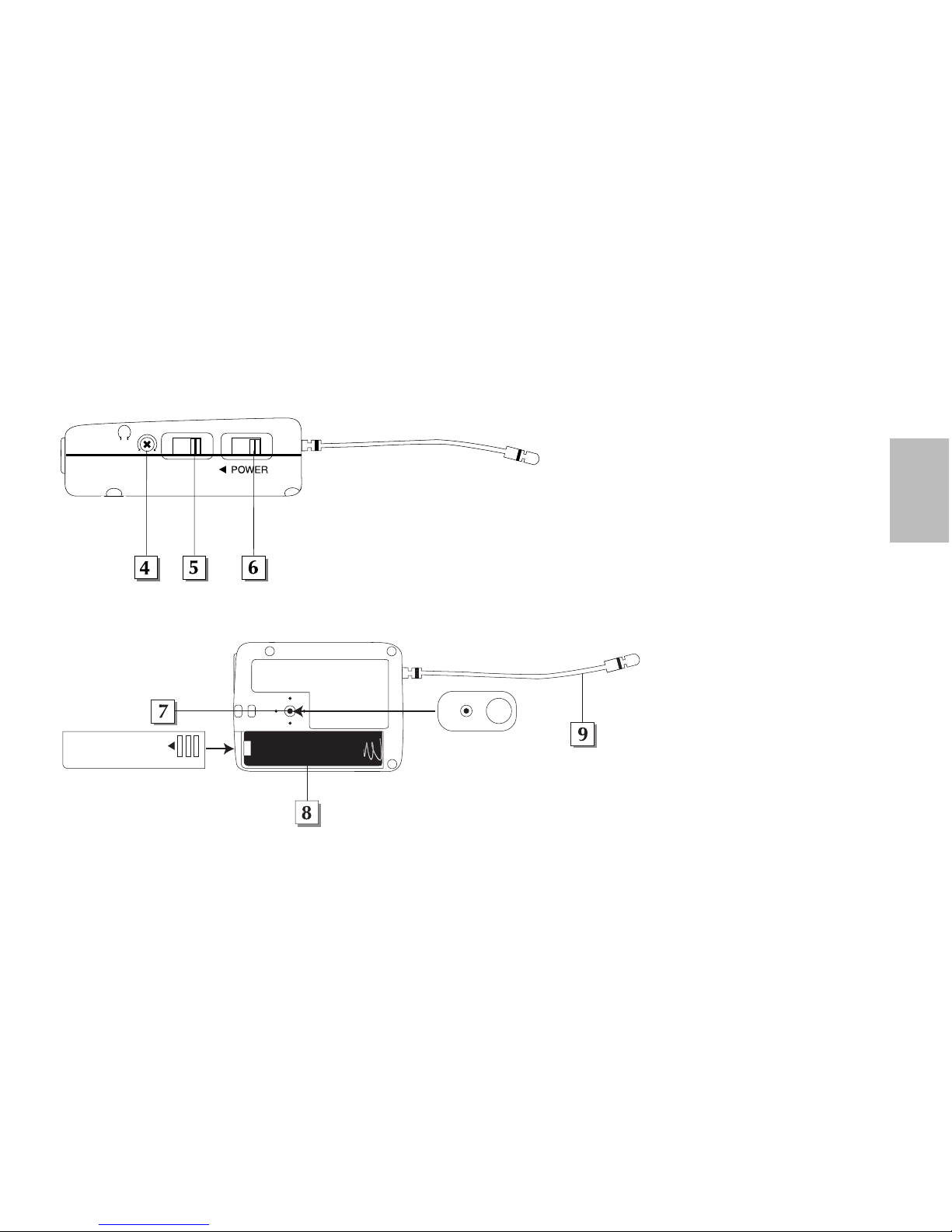
4:
Headphone Level Trimpot - Use this to adjust the volume
routed to the Headphone Output.
5:
Line/Mic Switch - This switch will set the correct signal level at
the Audio Output jack. Set the switch to Line when connecting
the output to a line level input as on a mixer. Set the switch to
Mic when connecting to Mic level input as on a camera.
(Check your equipment manuals for correct gain structure)
6:
Power Switch - Switches the Power on and off. The LED on the
front of the AM1 receiver will light momentarily when
switched on. (see #1 above)
AM1
OUTPUT
Guided Tour - AM1 Receiver
Samson AirLine
5
ENGLISH
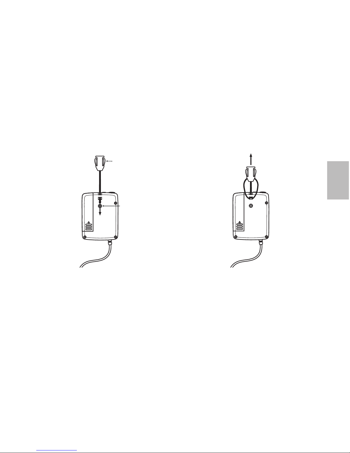
7: Hot Shoe Clip/Belt Clip - The AM1 is shipped with
the Belt Clip mounted to the rear of the receiver. The
hot shoe clip (included with hardware) can be fixed
to the rear of the AM1 to mount the receiver to the
hot shoe of your camera. To fasten the hot shoe clip
to the receiver, first remove the phillips head screw
and belt clip, then secure the hot shoe clip with the
supplied phillips head screw.
8:
Battery Compartment - Insert a standard AAA alkaline battery here, being sure to observe the plus and
minus polarity markings shown.
WARNING: Do not insert the battery
backwards; doing so can cause severe
damage to the AM1 and will void your
warranty.
9:
Antenna - Receives RF signal from
the transmitter. Once you have
selected the placement of the
receiver the antenna should be
turned to be in a vertical position
for optimum reception.
LINE MIC
LEVEL
+
_
Guided Tour - AX1 Handheld Transmitter
Samson AirLine
6
ENGLISH
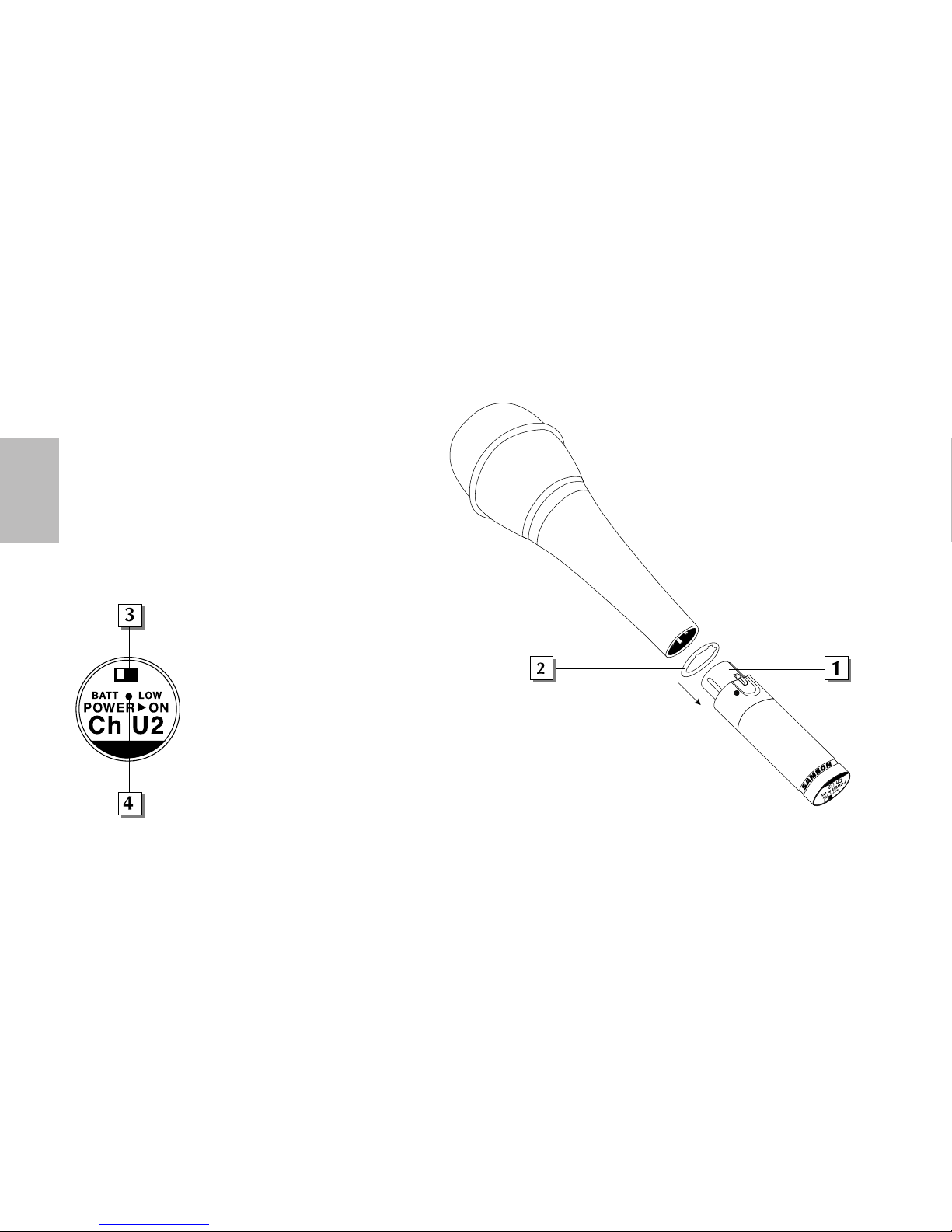
1: XLR connector - Connect this standard female XLR connector into any standard wired dynamic microphone in order to
make it a wireless mic.
2: Rubber gasket - If necessary, use this provided rubber gasket
in order to make a solid connection between the AX1 XLR
connector and your microphone (note that not all microphones
require its use).
3: Power on-off switch - Move this switch in the direction of
the arrow to turn power to the AX1 on; move it away from the
arrow to turn power off. (to conserve battery power, be sure to
turn the AX1 off when not in use).
Be sure to mute the audio signal at
your external mixer or amplifier
before turning the AX1 power on or
off, or an audible pop may result.
4: Power / Battery LED - This LED
flashes once when the AX1 is first
turned on and lights steadily red
when there is less than 2 hours of
battery power remaining, indicating
that the battery needs to be changed.
S
A
M
S
O
N
Guided Tour - AX1 Handheld Transmitter
Samson AirLine
7
ENGLISH
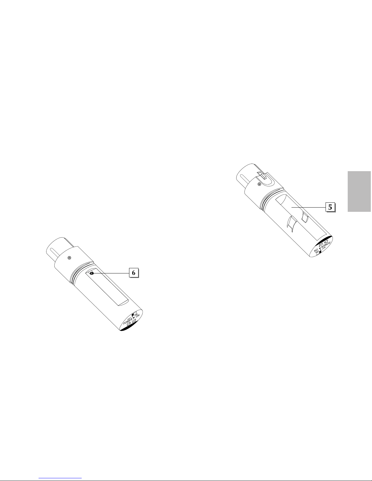
5: Battery compartment - Insert a standard AAA alkaline battery here,
being sure to observe the plus and minus polarity markings shown. We
recommend the Duracell type battery. Although rechargeable Ni-Cad
batteries can be used, they do not supply adequate current for more than
four hours.
WARNING: Do not insert the battery backwards; doing so can
cause severe damage to the AX1 and will void your warranty.
6: Microphone Input Level control (trimpot) - Use the supplied plastic
screwdriver to raise or lower the input level sensitivity of the AX1 as required.
See the “Setting Up and Using Your AirLine System” section on page 11 in this
manual for more information.
+
_
AF LEVEL
MIN
MAX
Guided Tour - AL1 Presentation Transmitter
Samson AirLine
8
ENGLISH
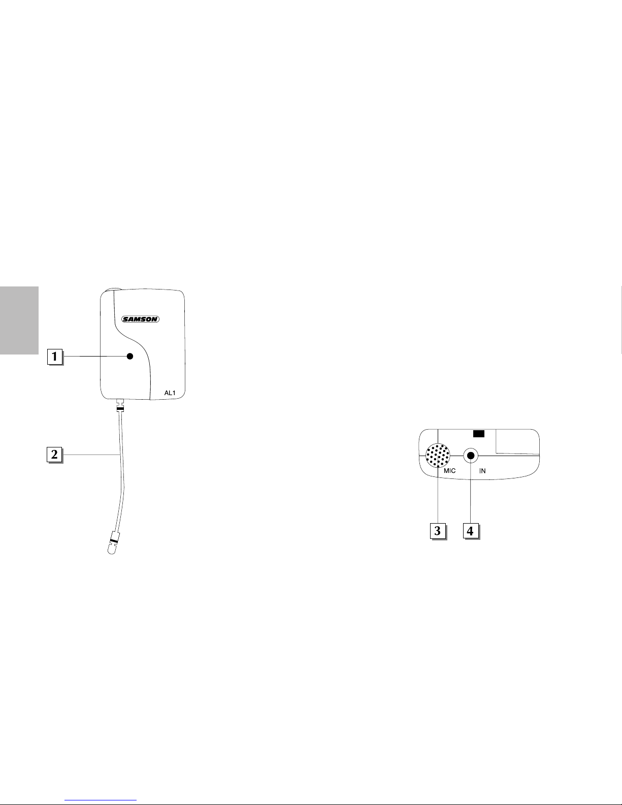
1: Power On/RF/ Battery LED - This LED flashes once when the AL1 is first turned on and
lights steadily red when there is less than 2 hours of battery power remaining, indicating that
the battery needs to be changed.
2: Antenna - This permanently attached flexible antenna should be fully extended during
normal operations. See the “Setting Up and Using Your AirLine System” section on page 11
in this manual for more information about antenna positioning.
3: Electret condenser microphone - This high- quality unidirectional electret condenser
microphone with metal windscreen is optimized for clear, crisp reproduction of speech. It
is active whenever the AL1 is powered on, as long as there is no connection made to the
lavalier microphone input connector (see #4 below). When a plug is inserted into the
lavalier microphone input connector, this built-in microphone is muted.
4: Lavalier microphone input connector - Use this
standard 2.5 mm mini-jack if you want to connect
an external lavalier microphone to the AL1.
Note that, because the AL1 has a built-in electret
condenser microphone (see #3 above), the use of an
external lavalier mic is optional and not required.
The AL1 provides 2.7V of phantom power, so
condenser mics can be used if desired.
Guided Tour - AL1 Presentation Transmitter
Samson AirLine
9
ENGLISH
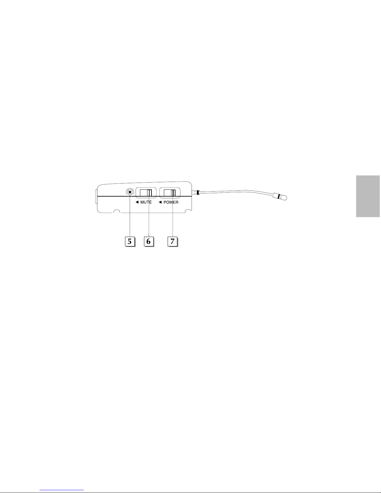
5: Gain control (trimpot) - Use the supplied plastic screwdriver to raise or lower the input level sensitivity of the AL1 as required.
See the “Setting Up and Using Your AirLine System” section on page 11 in this manual for more information.
6: Mute switch - Move this switch in the direction of the arrow to mute the AL1; move it away from the arrow to unmute it and
transmit audio signal
. Because the carrier signal remains during muting, no “pop” or “thud” will be heard. Note that turning this off
does
not turn off the transmitter power—it is simply a way to temporarily mute the transmission of audio signal. If you don’t plan on
using the AL1 for extended periods, turn it off power by using the power on-off switch (see #7 below). Be sure to mute the audio
signal at your external mixer or amplifier before turning the AL1 power on or off, or an audible pop may result.
7: Power switch - Move this switch in the direction of the arrow to turn power to the AL1 on; move it away from the arrow to turn
power off. (to conserve battery power, be sure to turn the AL1 off when not in use).
GAIN
Guided Tour - AL1 Presentation Transmitter
Samson AirLine
10
ENGLISH
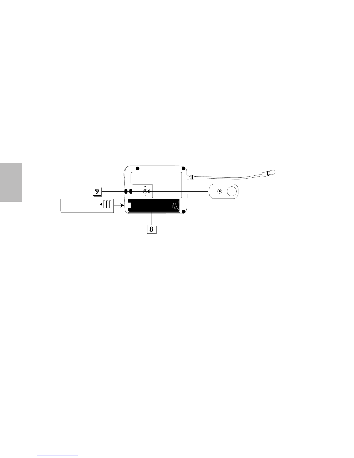
8: Battery compartment - Insert a standard AAA alkaline battery here, being sure to observe the plus and minus polarity markings
shown. We recommend the Duracell type battery. Although rechargeable Ni-Cad batteries can be used, they do not supply adequate
current for more than four hours.
WARNING: Do not insert the battery backwards; doing so can cause severe damage to the AL1
and will void your warranty.
9: Clip connector - This clip can be used to fasten the AL1 to a lapel or shirt pocket or to the supplied lanyard. The position of the
clip can be rotated to the desired position after loosening its center screw or can be removed entirely by removing the center screw.
For more information on positioning the AL1, see the “Setting Up and Using the AirLine System” section on page 11 and Appendix B
on page 86 in this manual.
+
_

Setting up and Using your AirLine System
Samson AirLine
11
ENGLISH
The basic procedure for setting up and using your AirLine System takes only a few minutes:
1. For your AirLine system to work correctly, both the receiver and transmitter must be set to the same channel. Remove all packing
materials (save them in case of need for future service) and check to make sure that the supplied receiver and transmitter are set to
the same channel (a complete channel plan is printed on the inside back cover of this manual). If these channels do not match,
contact your distributor or, if purchased in the United States, Samson Technical Support at 1-800-372-6766.
2. Place a fresh AAA alkaline battery in the AM1’s battery compartment, taking care to observe the polarity markings, and physically
place the receiver where it will be used (the general rule of thumb is to maintain “line of sight” between the receiver and transmitter
so that the person using or wearing the transmitter can see the receiver). The AM1 can be mounted on hot shoe of a video camera
using the supplied hot shoe clip, worn as a belt pack using the belt clip or fixed to any location with the supplied velcro.
3. Bend the antenna in a vertical position. Make sure the Power on-off switch in your transmitter is set to “Off.”
4a. If your system contains an AX1 handheld transmitter, unscrew the bottom section by turning it counterclockwise and then slide it off.
4b. If your system contains an AL1 body pack transmitter, turn it over and slide off the battery door.
5. Place a fresh AAA alkaline battery in the transmitter battery compartment, taking care to observe the polarity markings. If you are
using an AX1 transmitter, replace the bottom section by sliding it on and then screwing it back on. If you are using an AL1 transmitter, replace the battery door by sliding it in until it clicks. Whichever transmitter you are using, leave it off for the moment.
Setting up and Using your AirLine System
Samson AirLine
12
ENGLISH
6. Make the physical cable connection between the receiver output jack and a mic or line level audio input of your camera or mixer
(see wiring diagram on page 19 for options). Be sure to set the receiver’s Line/Mic switch correctly (see pages 4 for details). Leave
your camera (and/or mixer) off at this time.
7. Slide the Power switch in the direction of the arrow to turn on the receiver. The “Power/ RF” LED will light red momentarily.
8. Turn on the power to your transmitter (using its Power on-off switch); the “Power/Battery” LED will flash if the battery is sufficiently strong (if it lights steadily, the battery has less than 2 hours of power remaining and should be replaced). The “Power/ RF” LED
on the receiver should light green, indicating that it is receiving valid RF signal and is placed and positioned correctly.
9. Now it’s time to set the audio levels. Turn on your
connected camera and/or mixer but keep its volume
all the way down. If you are using an AL1 transmitter, make sure that it is unmuted (its Mute switch
should be positioned away from the arrow). If you
are using an AL1 transmitter with the built-in microphone, note that correct placement is critical to
sound quality. We recommend that you place it as
shown in the illustrations on this page—unobstructed by clothing and either clipped to a shirt pocket
or lapel, or worn around the neck on the supplied
lanyard.
SAMSON
SAMSON

Setting up and Using your AirLine System
Samson AirLine
13
ENGLISH
10. Speak or sing into your mic at a normal performance level while slowly raising the volume of your camera and/or mixer until the
desired level is reached. The AM1 receiver allows you to monitor the transmission signal using standard Walkman-type 30 ohm
headphones connected to its headphone jack. Note that Unidirectional microphones (mics which pick up signal from just one
direction) such as the built-in AL1 electret condenser are less prone to feedback than other types of mics. Any feedback problems
you encounter can be minimized by being sure not to use the microphone directly in front of a PA speaker or by using an equalizer to attenuate (reduce) those high- or mid-range frequencies which are causing the feedback “squealing”.
11. If you hear distortion at the desired volume level make sure that the gain structure of your audio system is correctly set (consult
the owners manual of your mixer and/or camera for details). If distortion persists try the following:
• If you are using an AX1 transmitter, use the supplied plastic screwdriver to turn its Microphone Input Level control (trimpot) slowly
counterclockwise (towards the “Min” position) until the distortion disappears.
• If you are using an AL1 transmitter with its internal electret condenser microphone, simply move the microphone further from
your mouth. If you are using an AL1 with an external lavalier microphone, use the supplied plastic screwdriver to turn the Gain
control (trimpot) slowly counterclockwise until the distortion disappears.
12. Conversely, if you hear a weak, noisy signal at the desired volume level, again make sure that the gain structure of your camera
and/or audio system is correctly set (consult the owners manual of your mixer and/or amplifier for details) If the signal coming
from the receiver is still weak and/or noisy, do the following:
• If you are using an AX1 transmitter, use the supplied plastic screwdriver to turn its Microphone Input Level control (trimpot) slowly
clockwise (towards the “Max” position) until the signal reaches an acceptable level.

Setting up and Using your AirLine System
Samson AirLine
14
ENGLISH
• If you are using an AL1 transmitter with its internal electret condenser microphone, simply position the microphone closer to your
mouth. If you are using an AL1 with an external lavalier microphone, use the supplied plastic screwdriver to turn the Gain control
(trimpot) slowly clockwise until the signal reaches an acceptable level.
13. When first setting up your AirLine System in a new environment, it’s always a good idea to do a walkaround in order to make sure
that coverage is provided for your entire performance area. Accordingly, turn down the level of your audio system and turn on
both the transmitter and receiver. Then, with the transmitter unmuted, restore the level of your audio system and while speaking or
singing, walk through the entire area that will need to be covered. As you do so, observe the LED on the receiver to make sure
that it is receiving sufficiently strong RF signal (the AM1 receiver “Power On / RF / Low Battery” LED should always remain lit
steadily green). Always try to minimize the distance between transmitter and receiver as much as possible so that the strongest
possible signal is received from all planned transmission points.
If you have followed all the steps above and are experiencing difficulties, contact your local distributor or, if purchased in the United
States, call Samson Technical Support (1-800-372-6766) between 9 AM and 5 PM EST.
Attaching the Lanyard to the AL1
Samson AirLine
15
ENGLISH
Transmitter
Tie Clasp
AL1 Tie Clip
Screw
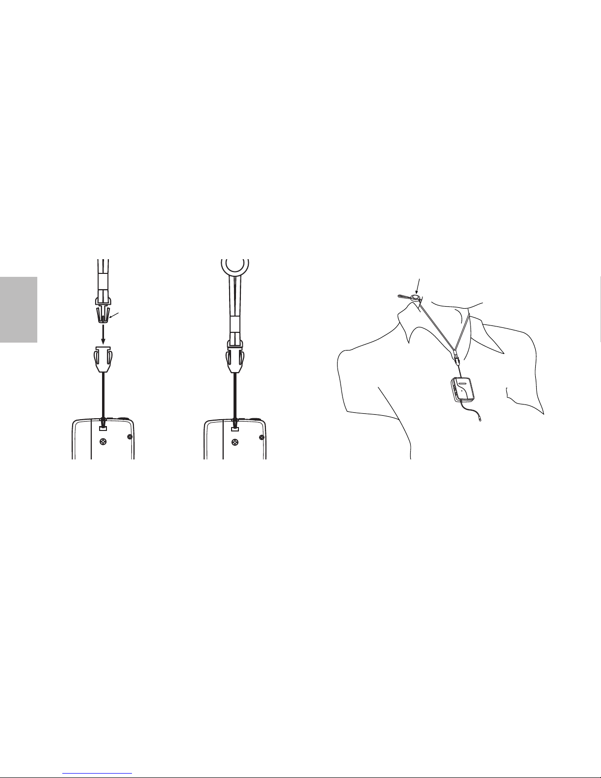
2. Pull the cord all the way through and lift it over the clasp,
making a loop. Pull the clasp through the loop taking up the slack.
1. Pass the cord from the Transmitter tie clip through the holes on
the top rear of the AL1. The clip may have to be rotated (and can
be removed) to reveal the exit hole. See page 16 in this manual for
further instructions. (For clarity, all the illustrations in this
Appendix show the AL1 with the tie clip removed.)
Attaching the Lanyard to the AL1
Samson AirLine
16
ENGLISH
Lanyard
Clip
S
A
M
S
O
N
Lanyard Length Adjustment Clasp
Press button to adjust
3. Place the lanyard over the head of the person using the
transmitter, adjusting the length with the lanyard length adjustment
clasp, which should be at the back of the person’s neck (refer to
the illustration above). Insert the lanyard clip into the AL1 tie clasp
until it snaps.
4. The AL1 should rest approximately in the middle of the chest of
the person speaking (see illustration above). To increase signal to
the mic, adjust the AL1 closer to the person’s mouth using the
lanyard length adjustment clasp. To temporarily remove the
lanyard from the AL1, squeeze the clasp and release the clip.
17
ENGLISH
Wiring Diagram
Samson AirLine
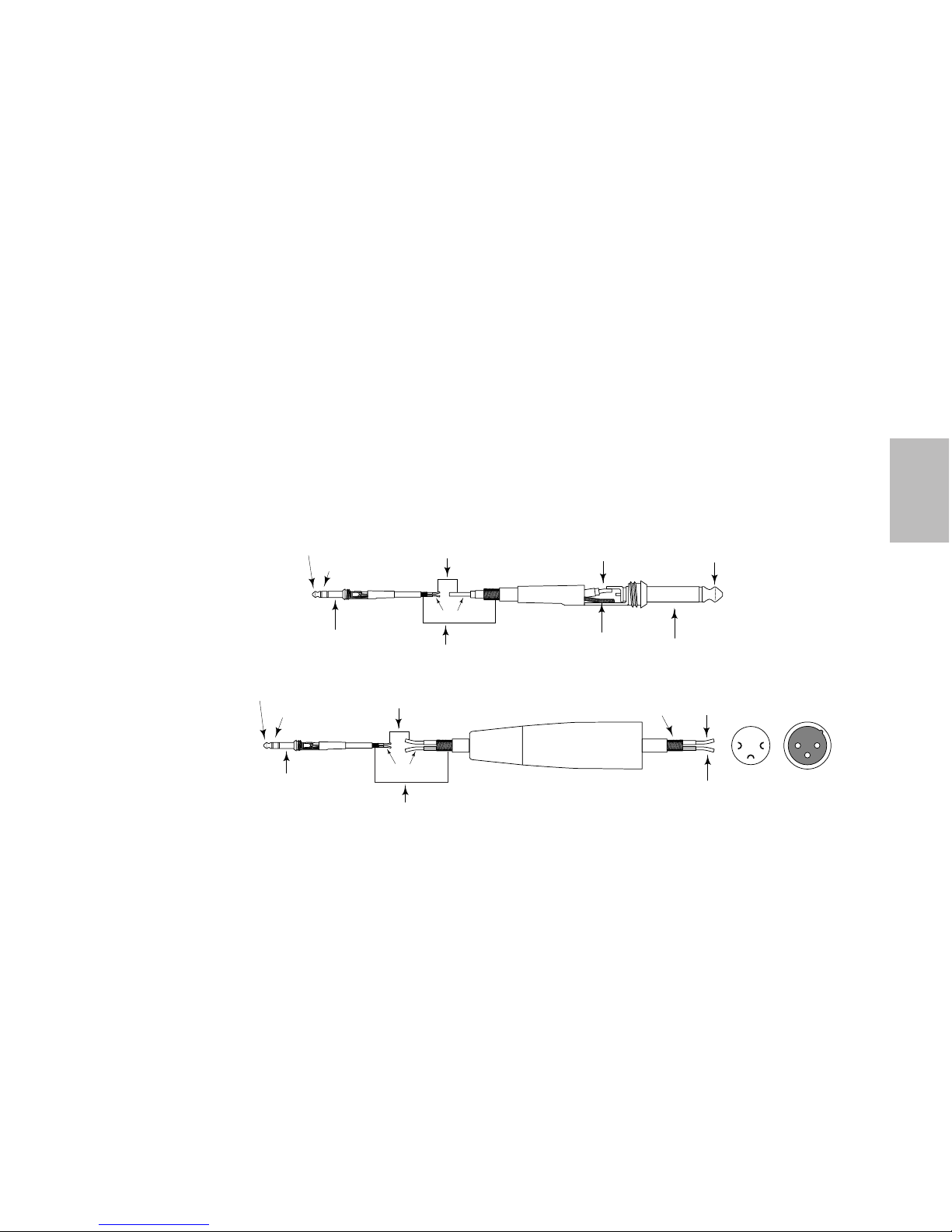
When connecting the output of the AM1 to a camera or mixer input, the supplied 2.5mm to 3.5mm SMM14 cable may not accommodate your needs. The wiring diagram below depicts common options. The SMM14’s 2.5 mm plug can be wired to either a 1/4
″
male phone plug or male XLR plug.
note: When connecting the 2.5mm plug to 1/4
″ phone plug the Tip and Sleeve from the 2.5mm plug are connected to the Tip and
Sleeve of the 1/4
″ phone plug. The Ring from the 2.5mm plug is not connected. When connecting the 2.5mm plug to an XLR plug,
the Ring from the 2.5mm plug and the cold (solder point number 3) do not make a connection.
2
3
1
12
3
Tip (signal)
Tip (signal)
Tip (signal)
Sleeve (ground)
Sleeve (ground)
Sleeve (ground)
Tip (signal)
Ring (no connection)
Ring to Pin 3
(no connection)
Ring (signal)
Sleeve (ground)
Signal
Ground
Tip (signal)
Ring (signal)
Sleeve (ground)
2.5mm to Male XLR
2.5mm to Male Phone
Hot(2)
Tip
Cold(3)
(Ring to Pin 3
no connection)
Common (1)
End View
Solder Points

Introduction
Merci d’avoir fait confiance au système Samson AirLine — le système sans fil du nouveau millénaire ! Les systèmes sans fil pour
micros et instruments ont été créés afin d’éliminer les câbles et offrir ainsi aux artistes une liberté de mouvement totale. Les systèmes
AirLine portent ce concept au stade ultime grâce à des émetteurs et des récepteurs si petits, légers et aérodynamiques qu’ils en sont
presque invisibles. Ces systèmes sans fil les plus compacts du marché bénéficient d’une toute nouvelle technologie brevetée. De plus,
grâce à l’emploi de circuits miniaturisés et de leur capacité à fonctionner à partir d’une seule pile AAA (pour une autonomie moyenne
de 14 heures), ces systèmes offrent une qualité de réception et une qualité sonore grandement améliorées. Ajoutons que le récepteur
micro AM1 développé tout spécialement pour le système AirLine est aussi petit que l’émetteur AL1.
Ce mode d’emploi porte sur deux systèmes AirLine Samson différents. Ces deux systèmes fonctionnent sur une bande de fréquences
UHF située entre 801 et 805 MHz et disposent chacun d’un récepteur micro AM1. Le système Microphone UHF AirLine est constitué
d’un émetteur main AX1 à brancher sur n’importe quel micro dynamique standard. Le système Presentation UHF AirLine est constitué
d’un émetteur de présentation AL1 équipé d’un micro condensateur à électret interne et d’un connecteur pour micro cravate.
Le présent manuel vous donne les caractéristiques de tous les systèmes AirLine, une visite guidée des éléments du système, la description détaillée du paramétrage des systèmes et les caractéristiques techniques. Si vous avez acheté votre système AirLine aux EtatsUnis, n'oubliez pas de remplir et de nous renvoyer la carte de garantie incluse. Vous pourrez grâce à elle bénéficier de notre assistance technique et être tenu au courant des dernières nouveautés Samson. Si vous avez acheté votre système AirLine hors des EtatsUnis, contactez votre revendeur pour de plus amples détails sur les clauses de la garantie. Vous pouvez également trouver des renseignements complets sur notre gamme de produits sur notre site Internet accessible à l’adresse http://www.samsontech.com.
NOTE : Contactez votre revendeur Samson pour toute demande de réparation.
Samson AirLine
18
FRANCAIS

Prise en main
Samson AirLine
19
FRANCAIS
Si vous êtes un habitué des systèmes sans fil, ce chapitre va vous permettre de configurer et d’utiliser votre système AirLine en
quelques minutes. Vous pouvez trouver les procédures de configuration et d’utilisation détaillées à partir de la page 11 du présent
mode d’emploi, ainsi qu’un “tour d’horizon” des commandes et des caractéristiques des systèmes AirLine.
1. Vérifiez que le récepteur AM1 et l’émetteur AX1 et/ou AL1 sont bien réglés d’usine sur le même canal.
2. Placez une pile neuve dans le récepteur AM1 et installez le récepteur à l’endroit où il doit être utilisé. Le récepteur AM1 peut être
monté sur une caméra au moyen de la pince ou de l’attache Velcro fournies.
3. Vérifiez que l’émetteur est hors tension (son interrupteur d’alimentation ne doit pas être dirigé vers la flèche), puis placez-y une
pile neuve. Mettez momentanément l’émetteur sous tension. Son témoin doit s’allumer brièvement puis s’éteindre si la pile est
suffisamment puissante. Une fois que vous avez vérifié l’état de la pile, éteignez l’émetteur.
4. Si vous utilisez un AX1, reliez un micro dynamique à son connecteur XLR. Assurez bien la connexion, si besoin est, au moyen du
joint en caoutchouc fourni. Si vous avez l’intention d’utiliser l’AL1 avec un micro cravate externe, reliez ce micro cravate à son
connecteur d’entrée.
5. Faites ensuite la connexion physique entre la sortie stéréo sur Jack 2,5 mm de l’AM1 et l’entrée audio de votre caméra ou de votre
console de mixage par le biais du câble SMM14 2,5 mm-3,5 mm fourni (vous pouvez en trouver le schéma de câble en page 19).
6. Adaptez le gain du récepteur AM1 à celui de l’entrée de la caméra ou de la console au moyen de son sélecteur MIC/LINE.

Samson AirLine
20
FRANCAIS
Prise en main
7. Mettez ensuite le récepteur sous tension. Le témoin POWER/BATTERY s’allume temporairement pour signaler que l’appareil est
sous tension.
8. Mettez l’émetteur sous tension. Vous pouvez avoir le retour du signal audio sur la sortie casque stéréo 3,5 mm. Une vis de
réglage permet de définir le volume de cette sortie (au moyen du tournevis en plastique fourni).
9. Allumez ensuite la caméra ou la console sans pour autant relever leur volume. Si votre système est constitué d’un émetteur AL1,
vérifiez que sa sortie n’est pas coupée, puis réglez-le au gain unitaire (potentiomètre Volume, Level ou AF placés complètement à
droite).
10. Parlez ou chantez dans le micro à niveau normal tout en relevant progressivement le volume de la caméra (si elle en est pourvue
d’un) ou de la console de mixage jusqu'au niveau désiré. Si besoin est, ajustez le niveau du signal au moyen de la vis de réglage
Gain et du tournevis en plastique fourni. Si vous utilisez un émetteur AL1 avec son micro interne, la qualité sonore finale dépend
en grande partie du bon placement de l’émetteur. Il ne doit pas obstrué ou être recouvert par des vêtements et doit être fixé à une
poche de chemise ou à une cravate ou bien porté autour du cou au moyen du cordon fourni.
11. Parcourez toute la surface devant être couverte tout en vérifiant le signal audio au niveau de la sortie casque ou de
l’afficheur de niveau d’entrée du récepteur AM1.
Samson AirLine
21
FRANCAIS
Tour d’horizon - Récepteur AM1
1: Témoin multicolore - Ce témoin s’allume brièvement en rouge à la mise sous tension et lors
de l’insertion d’une pile neuve. Il reste allumé en rouge en continu lorsque la pile est usée et
doit être remplacée. Ce témoin s’allume par ailleurs en vert lors de la réception d’ondes HF. Il
s’allume enfin en orange dans les cas où il doit s’allumer en vert et en rouge simultanément.
2:
Prise casque - Prise casque de type Jack 3,5 mm permettant d’écouter le signal audio.
3:
Sorie audio - Sortie Jack 2,5 mm à laquelle doit être relié le câble SMM14 2,5 mm-3,5 mm
stéréo fourni. Cette sortie transmet le signal audio à l’entrée audio de la caméra ou de la
console de mixage (voir n° 5 pour le réglage du niveau de sortie, et page 19 pour de plus
amples renseignements sur son câblage).
4:
Vis de réglage du niveau de la prise casque - Cette vis sert au
réglage du volume de sortie de la prise casque.
5:
Sélecteur Line/Mic - Ce sélecteur définit la nature du signal
émis sur la sortie audio. Placez-le sur Line si la sortie est reliée
à une entrée ligne (console, par ex). Placez-le sur Mic si elle
est reliée à une entrée micro (caméra). Veuillez à cet effet vous
reporter au mode d’emploi de votre appareil.
6:
Interrupteur marche/arrêt - Mettez l’appareil sous et hors
tension. Le témoin en façade du récepteur AM1 s’allume
brièvement à la mise sous tension. (Voir n° 1 ci-dessus).
AM1
OUTPUT
 Loading...