

SAMSON AirLine Owners Manual
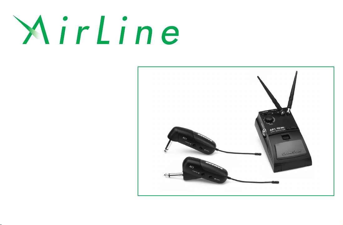
UHF Wireless System
Owners Manual
• AF1 Instrument Transmitter
• AG1 Instrument Transmitter
• AP1 Receiver
• AP1B Receiver
• UR1 Receiver
SAMSON

ENGLISH
Introduction 1
QuickStart 2
Guided Tour - AP1 Receiver 4
Guided Tour - AP1B Receiver 7
Guided Tour - UR1 Receiver 10
Guided Tour - AF1 / AG1 Transmitter 13
Setting Up and Using Your AirLine System 15
Specifications 69
Channel Plan 71
FRANCAIS
Introduction 18
Prise en main 19
Visite guidée – Récepteur AP1 21
Visite guidée – Récepteur AP1B 24
Visite guidée – Récepteur UR1 27
Visite guidée – Emetteur AF1 / AG1 30
Configuration et utilisation du système AirLine 32
Spécifications 69
Tableau de conversion de fréquence 71
Samson Technologies Corp.
575 Underhill Blvd.
P. O. Box 9031
Syosset, NY 11791-9031
Phone: 1-800-3-SAMSON (1-800-372-6766)
Fax: 516-364-3888
www.samsontech.com
Table of Contents
Produced by On The Right Wavelength for Samson Technologies Corp.
Copyright 2000, Samson Technologies Corp.
Reprinted October 2001
DEUTSCHE
Einleitung 35
Schneller Einstieg 36
Übersicht - Empfänger AP1 38
Übersicht - Empfänger AP1B 41
Übersicht - Empfänger UR1 35
Übersicht - Sender AF1 / AG1 47
AirLine System einrichten und einsetzen 49
Tec hnische Daten 69
Frequenzzuordnung der Empfangskanäle 71
ESPANOL
Introducción 52
Arranque rápido 53
Recorrido guiado – Receptor AP1 55
Recorrido guiado – Receptor AP1B 58
Recorrido guiado – Receptor UR1 61
Recorrido guiado – Transmisor AF1 / AG1 64
Ajuste y uso de su sistema AirLine 66
Especificaciones 69
Tabla de conversión de frecuencias 71
Note: All trademarks are the property of their respective holders
Samson AirLine

Welcome to Samson AirLine—the wireless system for the new millennium! Wireless microphone and instrument systems were
originally developed to eliminate cables, providing unparalleled freedom of movement. AirLine takes this concept to a new level with
transmitters so small, lightweight and aerodynamic, they are nearly invisible, providing a completely “hassle-free” user experience.
To create the world’s smallest wireless transmitters, we developed new proprietary technology. Featuring miniaturized circuitry and the
ability to operate on a single tiny AAA battery (with 14 hours typical battery life), these transmitters also provide significantly improved
wireless reception and sound quality. What’s more, the AP1 receiver developed especially for the AirLine guitar system is actually
smaller than the typical wireless transmitter.
The Samson AirLine UHF guitar system detailed in this manual is designed to replace the cable between your electric guitar or bass
and your onstage amplifier or PA mixer, freeing you to roam the stage or even visit the audience in the middle of your performance!
It operates in the uncrowded 801 – 805, 863 – 865 MHz UHF frequency range and contains an AP1 “stomp box”-style receiver and
either of two plug-in micro-transmitter models—an AF1 (designed to fit the recessed style jack in Fender Stratocaster™-type guitars) or
an AG1 (which fits all other standard end-mount guitar jacks).
In this manual, you’ll find a more detailed description of the features of your AirLine system, as well as a guided tour through all
components, step-by-step instructions for setting up and using your system and full specifications. If your AirLine system was
purchased in the United States, you’ll also find a warranty card enclosed—don’t forget to fill it out and mail it! This will enable you to
receive online technical support and will allow us to send you updated information about this and other Samson products in the
future. If your AirLine system was purchased outside of the U. S., contact your local distributor for warranty details. Also, be sure to
check out our website (http://www.samsontech.com) for complete information about our full product line.
SPECIAL NOTE for U.S. purchasers: Should your AirLine system ever require servicing, a Return Authorization number (RA) is
necessary. Without this number, the unit will not be accepted. If your AirLine system was purchased in the United States, please call
Samson at 1-800-372-6766 for a Return Authorization number prior to shipping your system. If possible, return the unit in its original
carton and packing materials. If your AirLine system was purchased outside of the U. S., contact your local distributor for information.
1
ENGLISH
Samson AirLine
Introduction

If you’ve had some prior experience using wireless systems, these QuickStart instructions will get you up and running with your
AirLine UHF guitar system in a matter of minutes! Detailed instructions for setting up and using your AirLine system can be found on
page 15 of this manual, and the “Guided Tour” sections on pages 4 - 14 provide full descriptions of all AirLine component controls
and displays.
1. Make sure that the supplied AP1 receiver and AF1 or AG1 transmitter are factory preset to the same channel.
2. Physically place the AP1 receiver on the ground in front of you. Extend its antennas vertically and spread the tips horizontally outwards approximately 5 inches.
3. Set the power switch on your AF1 or AG1 transmitter to the “off” position (away from the arrow) and place a fresh AAA battery in it.
Then turn the transmitter back on momentarily; its LED will flash once and then go off if the battery is sufficiently strong. Once
battery strength is verified, turn the transmitter off again, then plug it into your electric guitar or bass.
4. Open the battery compartment of the AP1 by pressing on the latch and install a fresh battery; if you prefer, you can use an optional
power supply instead. Turn the AP1 on momentarily to confirm that the battery has been installed correctly (or that the adapter has
been connected correctly); the “On/Battery Low” LED should light green and not red. Then turn the AP1 power off.
5. Turn your amplifier or mixer off and make the physical cable connection between an audio input and the AP1 output jack.
6. Turn the Level knob on the AP1 completely counterclockwise, then turn its power on; the “Power” LED will light steadily green.
7. Turn on your AF1 or AG1 transmitter. The “TX/Peak” LED on the AP1 receiver should light steadily green, indicating that it is
receiving valid RF signal and is placed and positioned correctly.
2
QuickStart
ENGLISH
Samson AirLine

8. Turn on the connected amplifier or mixer but keep its volume all the way down. Set the output level of your instrument to maximum and begin playing at a normal performance level while observing the AP1 “TX/Peak” LED. If the LED lights red (indicating a
Peak condition) even with the AP1 Level control fully counterclockwise, engage the 15 dB pad on the transmitter. If not, slowly turn
the Level control clockwise to the point where the “TX/Peak” LED occasionally blinks red during the very loudest passages, then back
it off just slightly. Finally, raise the level of your connected amplifier and/or mixer until the desired volume is reached.
9. Do a walkaround through the intended area of coverage while observing the receiver’s “TX/Peak” LED; it should continue to be lit
steadily green, indicating sufficient RF reception in all areas of coverage. If not, reposition the AP1 or its antennas as necessary.
10. If you hear any spurious noise from the receiver output when the transmitter is turned off, use the supplied plastic screwdriver to
adjust the AP1 Squelch control, slowly turning it clockwise to the point at which the noise disappears.
3
QuickStart
ENGLISH
Samson AirLine
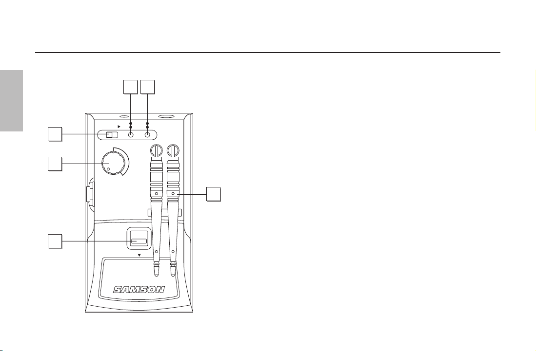
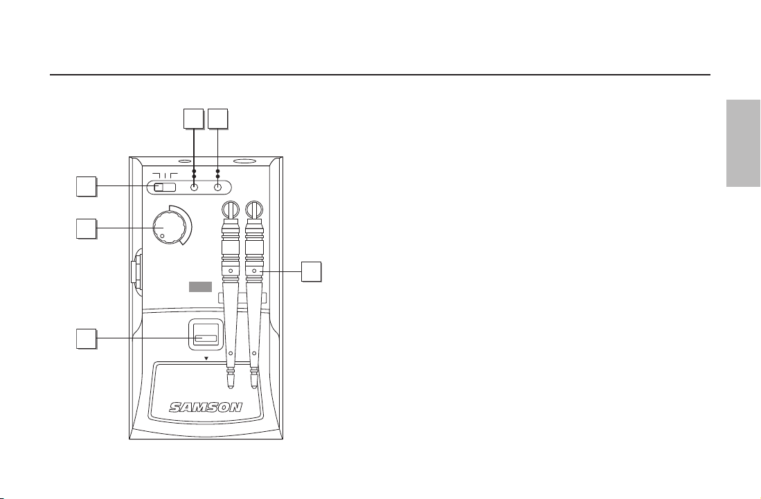
1: Power switch - Move this switch in the direction of the arrow to turn
power to the AP1 on; move it away from the arrow to turn power off. (A
jack must be inserted into the input connector for the receiver to power up.)
2: Power On / Battery Low LED - This LED lights green whenever the
AP1 is powered on and it lights red whenever the battery in the AP1 is
running low. In order to avoid compromising audio fidelity (or having
the AP1 stop working completely), you should always replace the battery with a fresh one immediately whenever this LED lights red.
3: TX / Peak LED - This LED lights green whenever the AP1 is receiving
RF signal from a transmitter and it lights red when output signal from
the AP1 is at the onset of clipping (that is, when it is on the verge of
being distorted). If you see this light during operation, lower the volume level of your instrument or switch on the transmitter’s 15 dB pad.
For more information, see the section entitled “Setting Up and Using
Your AirLine System” on page 15 in this manual.
4: Level control - This knob sets the level of the audio signal being
output through the AP1 output jack (see #9 on page 9). When using an
electric guitar or bass with an active or high-level pickup, set the knob
in the marked area. For more information, see the section entitled
“Setting Up and Using Your AirLine System” on page 15 in this manual.
4
Guided Tour - AP1 Receiver
ENGLISH
Samson AirLine
1
4
6
2 3
POWER
BATT. LOWONPEAK
A
•
C
T
I
V
E
&
•
H
I
L
E
V
•
E
L
P
I
C
•
K
U
P
S
•
∞
LEVEL
AP1
UHF RECEIVER
OPEN
TX
5
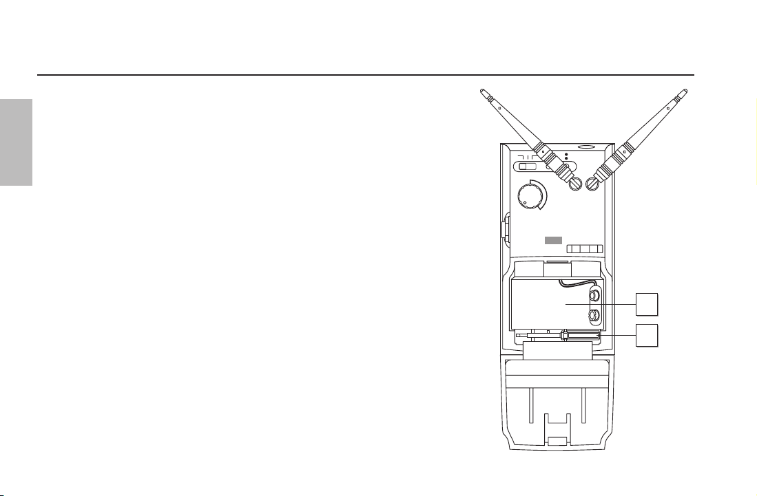
5: Antennas - Swivel mounting allows full rotation for optimum positioning of the
dual AP1 antennas. In normal operation, extend both antennas vertically and
spread the tips horizontally outwards approximately 5 inches. For convenience,
they can be folded inward when transporting the AP1. See the “Setting Up and
Using Your AirLine System” section on page 15 in this manual for more information
about antenna positioning.
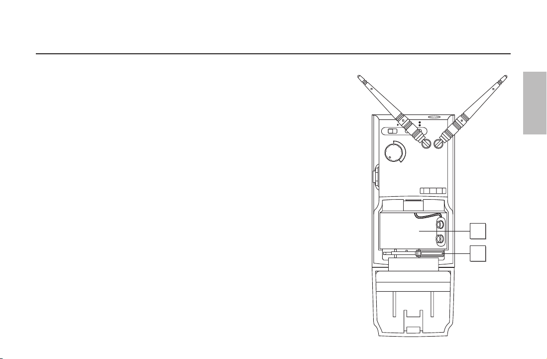
6: Battery compartment latch - Press gently on this latch to open the AP1 battery
compartment (see #7 below).
7: Battery compartment - Insert a standard 9-volt alkaline battery here, being sure
to observe the plus and minus polarity markings shown. We recommend the
Duracell MN 1604 type battery. Although rechargeable Ni-Cad batteries can be
used, they do not supply adequate current for more than four hours.
WARNING: Do not insert the battery backwards; doing so can cause severe damage to the AP1 and will void your warranty. Note that the AP1 can also be AC
powered with the use of an optional 12 volt adapter available from your Samson
dealer (see #10 on the following page).
8: Plastic screwdriver - Specially designed for use in adjusting the AP1 Squelch
control (see #11 on the following page). See the “Setting Up and Using Your
AirLine System” section on page 15 in this manual for more information.
Guided Tour - AP1 Receiver
ENGLISH
5
Samson AirLine
POWER
A
•
C
T
I
V
E
&
•
H
I
L
E
V
•
E
L
P
I
C
•
K
U
P
S
•
∞
LEVEL
AP1
UHF RECEIVER
BATT. LOWONPEAK
TX
SAMSON
7
8
Guided Tour - AP1 Receiver
6
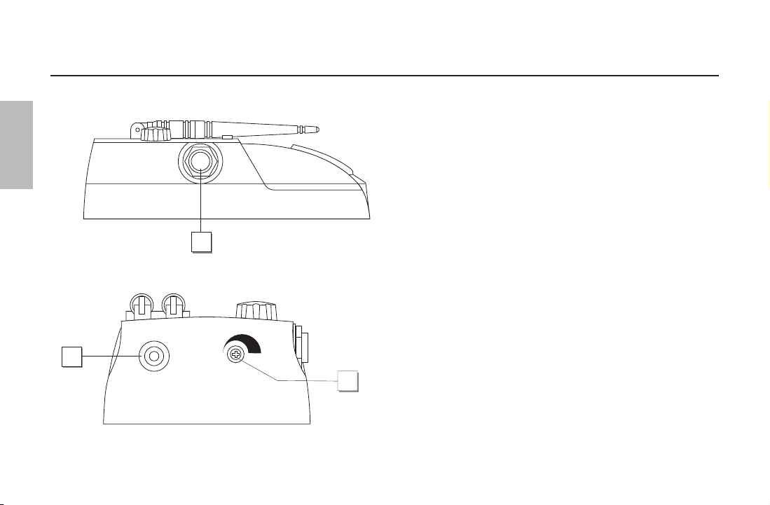
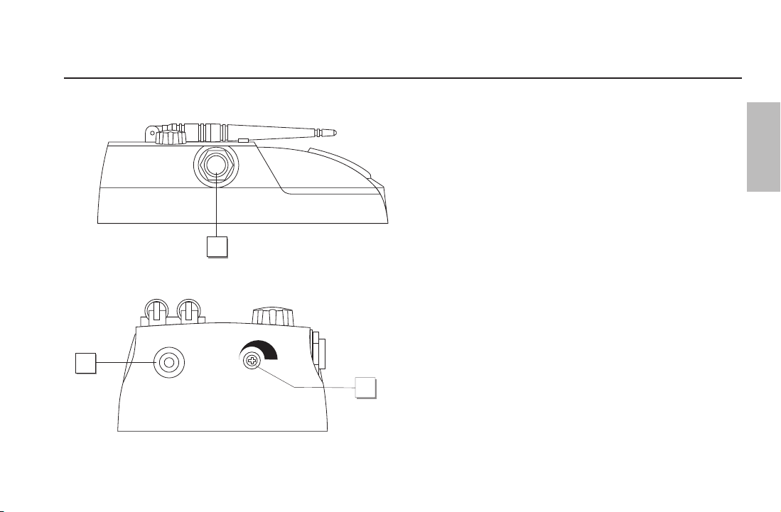
9: Output jack - Use this standard unbalanced high
impedance (5 - 10 K Ohm) 1/4" jack to connect the AP1 to
your amplifier or audio mixer. Wiring is as follows: tip hot,
sleeve ground.
10: DC input - Connect an optional 12 volt 200 mA power
adapter (available from your Samson dealer) here.
WARNING: Do not substitute any other kind of power
adapter; doing so can cause severe damage to the AP1 and
will void your warranty. Note that the AP1 can also be
battery powered (see #7 on the previous page and the
“Setting Up and Using Your AirLine System” section on page
15 in this manual).
11: Squelch control - This control determines the maximum
range of the AP1 before audio signal dropout. Although it
can be adjusted using the supplied plastic screwdriver, it
should normally be left at its factory setting. See the “Setting
Up and Using Your AirLine System” section on page 15 in this
manual for more information.
ENGLISH
Samson AirLine
10
OUTPUT
DC INPUT
12 VDC
9
MIN MAX
SQUELCH
11
Guided Tour - AP1B Receiver
1: Power On-Off / Shape switch - Move this switch to the ON position
to turn power to the AP1B on; move it to the SHAPE position to engage
the shape circuitry yielding a fat bottom end and fullness in tone; move it
back towards the OFF position to turn power off. (A jack must be inserted
into the input connector for the receiver to power up.)
2: Power On / Battery Low LED - This LED lights green whenever the
AP1B is powered on and it lights red whenever the battery in the AP1B is
running low. In order to avoid compromising audio fidelity (or having the
AP1B stop working completely), you should always replace the battery
with a fresh one immediately whenever this LED lights red.
3: TX / Peak LED - This LED lights green whenever the AP1B is receiving
RF signal from a transmitter and it lights red when output signal from the
AP1B is at the onset of clipping (that is, when it is on the verge of being
distorted). If you see this light during operation, lower the volume level
of your instrument or switch on the transmitter’s 15 dB pad. For more
information, see the section entitled “Setting Up and Using Your AirLine
System” on page 15 in this manual.
4: Level control - This knob sets the level of the audio signal being output through the AP1B output jack (see #9 on page 9). When using an
electric guitar or bass with an active or high-level pickup, set the knob in
the marked area. For more information, see the section entitled “Setting
Up and Using Your AirLine System” on page 15 in this manual.
ENGLISH
7
Samson AirLine
2 3
ONON SHAPEOFF
POWER
BATT. LOW
TX
PEAK
1
A
•
C
T
I
V
E
&
•
H
I
L
E
V
•
E
L
P
4
I
C
•
K
U
P
S
•
∞
LEVEL
5
Bass
AP1B
UHF RECEIVER
6
OPEN
Guided Tour - AP1B Receiver
5: Antennas - Swivel mounting allows full rotation for optimum positioning of the
dual AP1B antennas. In normal operation, extend both antennas vertically and
spread the tips horizontally outwards approximately 5 inches. For convenience, they
can be folded inward when transporting the AP1B. See the “Setting Up and Using
Your AirLine System” section on page 15 in this manual for more information about
antenna positioning.
6: Battery compartment latch - Press gently on this latch to open the AP1B battery
compartment (see #7 below).
7: Battery compartment - Insert a standard 9-volt alkaline battery here, being sure to
observe the plus and minus polarity markings shown. We recommend the Duracell
MN 1604 type battery. Although rechargeable Ni-Cad batteries can be used, they do
not supply adequate current for more than four hours.
WARNING: Do not insert the battery backwards; doing so can cause severe damage
to the AP1B and will void your warranty. Note that the AP1B can also be AC powered with the use of an optional 12 volt adapter available from your Samson dealer
(see #10 on the following page).
8: Plastic screwdriver - Specially designed for use in adjusting the AP1B Squelch
control (see #11 on the following page). See the “Setting Up and Using Your AirLine
System” section on page 15 in this manual for more information.
ENGLISH
8
Samson AirLine
ON SHAPEOFF
POWER
A
•
C
T
I
V
E
&
•
H
I
L
E
V
•
E
L
P
I
C
•
K
U
P
S
•
∞
LEVEL
AP1B
UHF RECEIVER
BATT. LOWONPEAK
Bass
TX
SAMSON
7
8
Guided Tour - AP1B Receiver
9: Output jack - Use this standard unbalanced high
impedance (5 - 10 K Ohm) 1/4" jack to connect the AP1B to
your amplifier or audio mixer. Wiring is as follows: tip hot,
sleeve ground.
10: DC input - Connect an optional 12 volt 200 mA power
adapter (available from your Samson dealer) here.
WARNING: Do not substitute any other kind of power
adapter; doing so can cause severe damage to the AP1B and
will void your warranty. Note that the AP1B can also be
battery powered (see #7 on the previous page and the
“Setting Up and Using Your AirLine System” section on page
15 in this manual).
11: Squelch control - This control determines the maximum
range of the AP1B before audio signal dropout. Although it
can be adjusted using the supplied plastic screwdriver, it
should normally be left at its factory setting. See the “Setting
Up and Using Your AirLine System” section on page 15 in this
manual for more information.
ENGLISH
9
Samson AirLine
10
OUTPUT
DC INPUT
12 VDC
9
MIN MAX
SQUELCH
11
ENGLISH
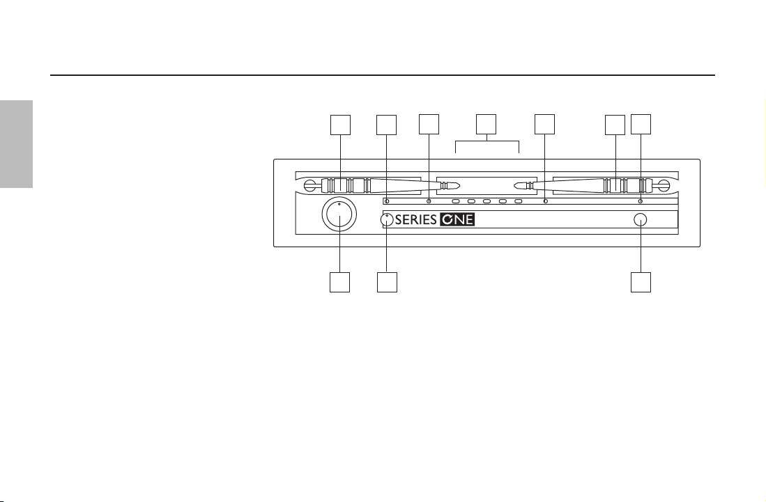
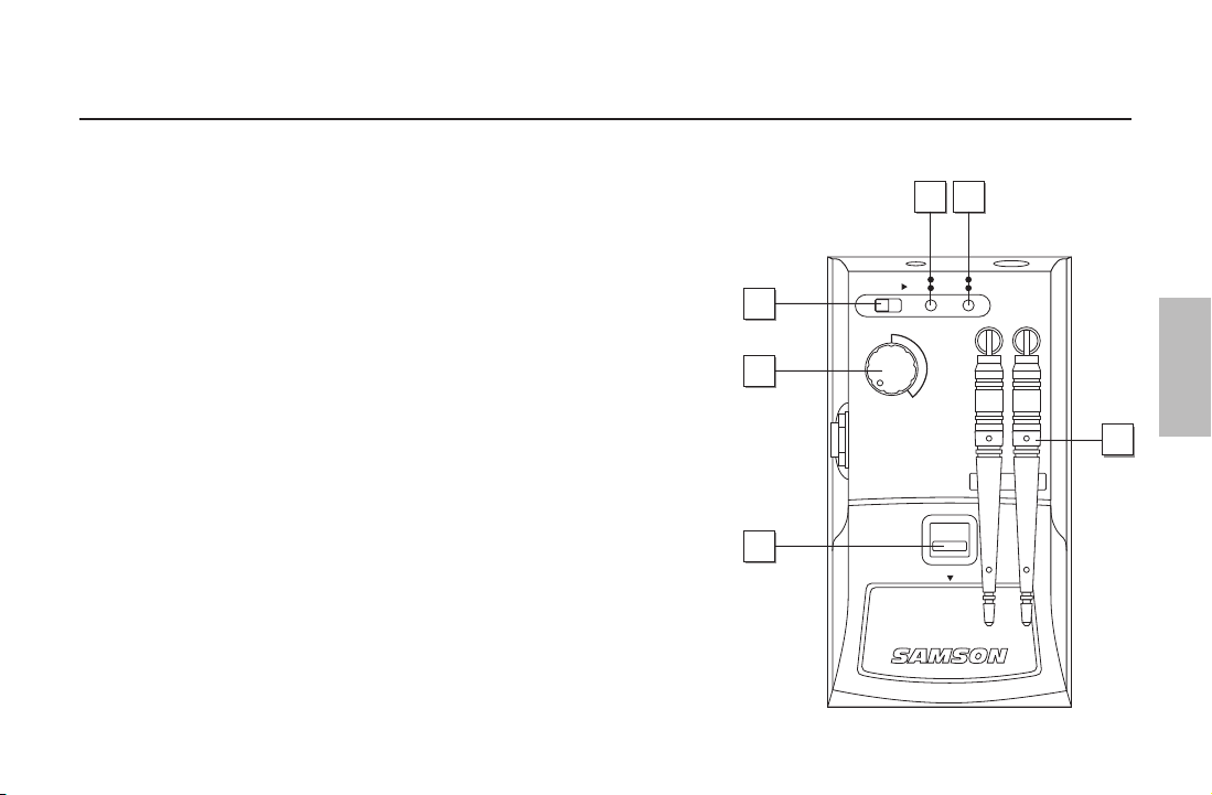
1: Antennas (A and B) - The
antenna mountings allow full
rotation for optimum placement.
In normal operation, both Antenna
A (the antenna on the left) and
Antenna B (the antenna on the
right) should be placed in a vertical
position. Both antennas can be
folded inward for convenience
when transporting the UR1. See
the “Setting Up and Using the
AirLine System” section on page
15 in this manual for information
about antenna installation and
positioning.
2: AF (Audio Frequency) Level control - This knob sets the level of the audio signal being output through both the balanced and
unbalanced output jacks on the rear panel (see #2 and #4 on page 12 in this manual). Reference level is obtained when the knob is
turned fully clockwise (to its “10” setting).
3: Peak LED - This LED lights yellow when output signal from the UR1 is at the onset of clipping (that is, when it is on the verge of
being distorted). If you see this light during operation, move the microphone further away or lower the output level of your
instrument or transmitter. For more information, see the section entitled “Setting Up and Using the AirLine System” on page 15 in
this manual.
Guided Tour - UR1 Receiver / Front Panel
10
Samson AirLine
1
2
3
7
4
5
4
1
SAMSON
UHF RECEIVER
6
8

11
4: A/B Receiver LEDs - When signal is being received, one of these will be lit green, showing you whether the (left) “A” or (right) “B”
receiver is currently being used. The UR1 constantly scans its two antennas and automatically selects whichever is receiving the
strongest, clearest signal. This True Diversity switching is completely inaudible, but it effectively increases overall range while
virtually eliminating potential interference and phase cancellation problems.
5: RF (Radio Frequency) Level meter - This five-segment meter (similar to the VU bar meter used on audio devices) indicates the
strength of the UHF signal being received. When all segments are lit, the incoming RF signal is at optimum strength; when only the
left-most segment is lit, the incoming RF signal is at minimum strength. If no segments are lit, no signal is being received; check to
ensure that the transmitter is on and that it is set to the same channel as the UR1. See the “Setting Up and Using the AirLine System”
section on page 15 in this manual for more information.
6: Power LED - This lights red whenever the UR1 is turned on.
7: Mute (squelch) control - This control determines the maximum range of the UR1 before audio signal dropout. Although it can be
adjusted using the supplied plastic screwdriver, it should normally be left at its factory setting. See the “Setting Up and Using the
AirLine System” section on page 15 in this manual for more information.
8: Power switch - Use this to turn the UR1 power on and off. When the receiver is on, the Power LED (see #6 above) is lit.
Guided Tour - UR1 Receiver / Front Panel
ENGLISH
Samson AirLine
ENGLISH
12
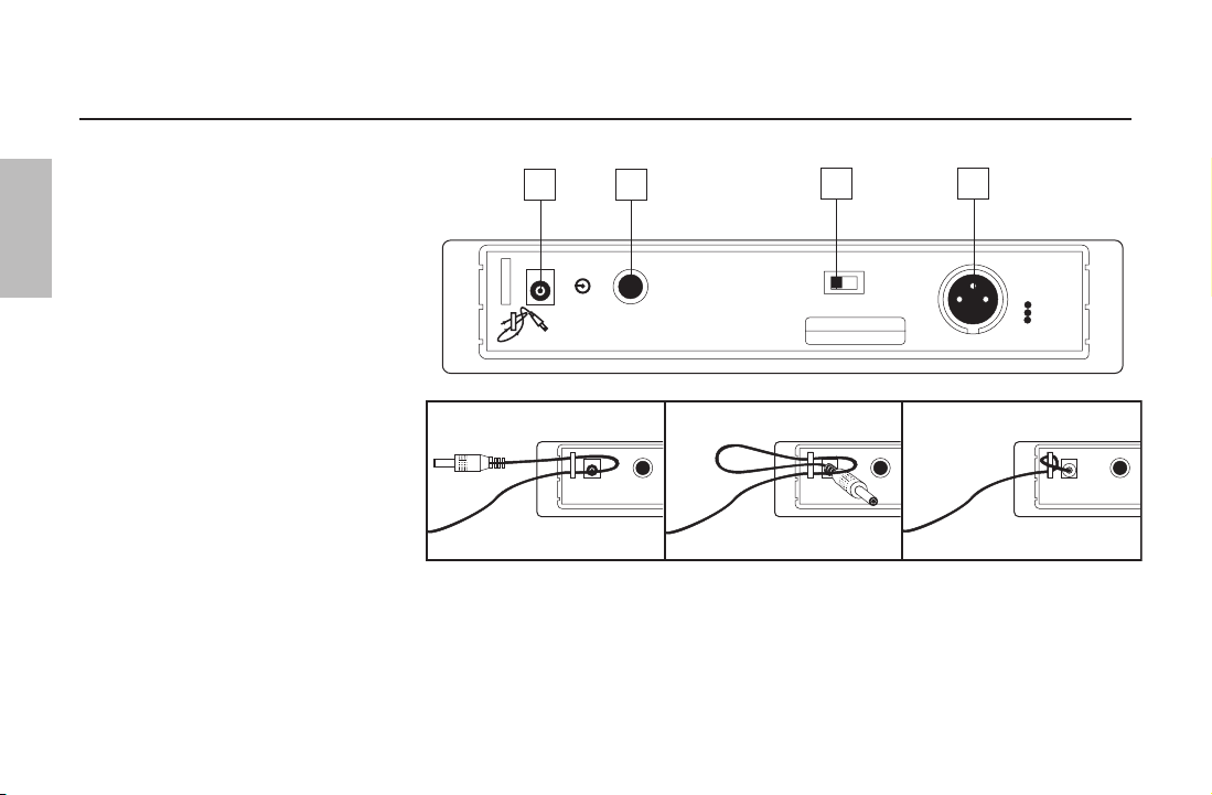
1: DC input - Connect the supplied
12 volt 160 mA power adapter here,
using the strain relief as shown in the
illustration below. WARNING: Do not
substitute any other kind of power
adapter; doing so can cause severe
damage to the UR1 and will void your
warranty.
2: Unbalanced output* - Use this
unbalanced high impedance (5K Ohm)
1/4" jack when connecting the UR1 to
consumer (-10) audio equipment.
Wiring is as follows: tip hot, sleeve
ground.
3: Audio Output Level switch - Sets
the audio output level attenuation of
the balanced output (see #4 below) to
-20 dBm (line level) or -40 dBm
(mic level). See “Setting Up and Using the AirLine System” on page 15.
4: Balanced output* - Use this electronically balanced low impedance (600 Ohm) XLR jack when connecting the UR1 to professional
(+4) audio equipment. Pin wiring is as follows: Pin 1 ground, Pin 2 high (hot), and Pin 3 low (cold).
* If required, both the unbalanced and balanced outputs can be used simultaneously.
Guided Tour - UR1 Receiver / Rear Panel
Samson AirLine
1
DC INPUT
AC CABLE LOCK
CAUTION:
USE SAMSON
AC ADAPTOR
CABLE LOCK: LOOP THRU AND TIE
2
UNBALANCED
OUTPUT
+
-
-10dB 5K
ONLY
3 4
BALANCED SWITCH
LINE:
-20dBm600
MIC:
-40dBm600
MIC
LINE
POWER RATING
DC 12V, 1.9W(160mA)
-
BALANCED OUTPUT
XLR:
1 GND
2 HOT
3 COLD
13
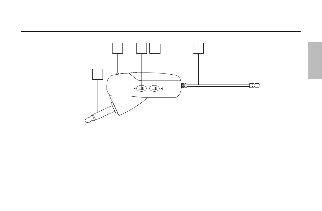
Note: The AF1 and AG1 transmitters are functionally identical apart from the angling of the 1/4” plug. For purposes of illustration,
only the AF1 is shown on these pages.
1: Plug - Insert this standard 1/4” plug into your electric guitar or electric bass. Note that the angling of the plug is different in the
AF1 (which is designed to be used with instruments that have Fender Stratocaster™-type recessed jacks) than in the AG1 (which is
designed to be used with all other instruments that have end mount-jacks).
2: Power / Battery LED - This LED flashes once when the AF1 or AG1 is first turned on and lights steadily red when there are less than
2 hours of battery power remaining, indicating that the battery needs to be changed. In order to avoid compromising audio fidelity (or
having the AF1 / AG1 stop working completely), you should always replace the battery with a fresh one immediately whenever this
LED lights red.
Guided Tour - AF1 / AG1 Transmitters
ENGLISH
Samson AirLine
32
4 5
1
AF1
POWER15dB PAD
Guided Tour - AF1 / AG1 Transmitters
14
3: 15 dB Pad - Move this switch in the direction of the arrow to
reduce the output of the AF1 or AG1 by 15 dB when your
instrument is putting out too hot a signal. See the “Setting Up and
Using the AirLine System” section on page 15 in this manual.
4: Power switch - Move this switch in the direction of the arrow
to turn power to the AF1 or AG1 on; move it away from the arrow
to turn power off.
5: Antenna - This permanently attached flexible antenna should
be fully extended during normal operations. See the “Setting Up
and Using the AirLine System” section on page 15 in this manual
for more information about antenna positioning.
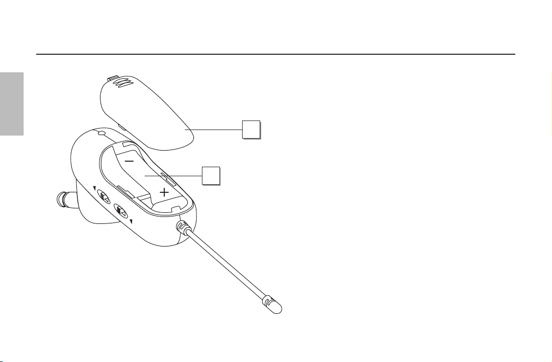
6: Battery cover - Pull back gently on this cover at the ribbing
and pry upwards to remove. See the “Setting Up and Using the
AirLine System” section on page 15 in this manual.
7: Battery compartment - Insert a standard AAA alkaline battery
here, being sure to observe the plus and minus polarity markings
shown. We recommend the Duracell type battery. Although
rechargeable Ni-Cad batteries can be used, they do not supply
adequate current for more than four hours. WARNING: Do not
insert the battery backwards; doing so can cause severe damage
to the AF1 / AG1 and will void your warranty.
ENGLISH
Samson AirLine
AF
1
15dB PAD
SAMSON
6
7
POWER

15
The basic procedure for setting up and using your AirLine System takes only a few minutes:
1. For your AirLine system to work correctly, both the receiver and transmitter must be set to the same channel. Remove all packing
materials (save them in case of need for future service) and check to make sure that the supplied AP1 receiver and AF1 or AG1
transmitter are set to the same channel (a complete channel plan is printed on page 71 in this manual). If these channels do not
match, contact your distributor or, if purchased in the United States, Samson Technical Support at 1-800-372-6766.
2. Physically place the AP1 receiver on the ground in front of you. It works best in this position. The general rule of thumb is to maintain “line of sight” between the receiver and transmitter so that the person using the transmitter can see the receiver.
3. Extend the AP1 antennas and spread the tips horizontally outwards approximately 5 inches.
4. Make sure the Power On-Off switch in your AF1 or AG1 transmitter is set to “Off” and that the 15 dB pad is also Off (switch away
from the direction of the arrow). Pull back gently on the AF1 or AG1 battery cover at the ribbing and pry it upwards to remove it.
Please use care when opening this cover as undue force can damage it. Install a fresh AAA alkaline battery in the battery
compartment, being sure to observe the polarity markings. Then carefully replace the battery cover and gently press down on it
until it clicks. Momentarily turn on the power to the transmitter by sliding its Power on-off switch in the direction of the arrow; the
“Power/Battery” LED will flash if the battery is sufficiently strong (if it lights steadily, the battery has less than 2 hours of power
remaining and should be replaced). Once battery strength is verified, turn the transmitter off again and plug it into your electric guitar
or bass.
5. With the Power switch on the AP1 set to the “Off” position (away from the arrow), gently press down on the AP1 battery
compartment latch and swing the battery compartment door open (do not use force when opening or closing the battery door; it is
hinged and not meant to be removed). Install a fresh 9-volt battery, then carefully close the battery door. Alternatively, you can
connect a 12-volt AC adapter (available as an option from your Samson dealer). Turn the AP1 on momentarily to confirm that the
Setting Up and Using Your AirLine System
ENGLISH
Samson AirLine

16
battery has been installed correctly (or that the adapter has been connected correctly); the “On/Battery Low” LED should light green
and not red. Then turn the AP1 power off.
6. Make the physical cable connection between the AP1 output jack and an audio input of your amplifier or mixer. Leave your amplifier or mixer off at this time.
7. Turn the Level knob on the AP1 completely counterclockwise, then slide its Power switch in the direction of the arrow to turn it on.
The “Power On” LED will light steadily green.
8. Turn on the power to the transmitter. The “TX / Peak” LED on the AP1 receiver should now light steadily green, indicating that it is
receiving valid RF signal and is placed and positioned correctly.
9. Now it’s time to set the audio levels. Turn on your amplifier and/or mixer but keep its volume all the way down. Set the output
level of your electric guitar or bass to maximum and begin playing it at a normal performance level while observing the AP1 “TX/Peak”
LED. If the LED lights red (indicating a Peak condition) even with the AP1 Level control fully counterclockwise, engage the 15 dB pad
on your transmitter by sliding the switch in the direction of the arrow. If not, slowly turn the AP1 Level control clockwise to the point
where the “TX/Peak” LED occasionally blinks red during the very loudest passages, then back it off just slightly; this will ensure maximum signal to noise ratio. Finally, raise the level of your amplifier and/or mixer until the desired volume is reached.
10. If you hear distortion or the AP1 “TX/Peak” LED lights red even with the 15 dB pad engaged and the Level control at minimum
(fully counterclockwise), reduce the output level of your instrument until the LED no longer lights red. Conversely, if you hear a weak,
noisy signal at the desired volume level, make sure that your instrument is set to maximum output level, that the 15 dB pad is not
engaged, and that the AP1 Level control is turned up. When using instruments with active or high level pickups, the Level control
should normally be set in the marked region.
Setting Up and Using Your AirLine System
ENGLISH
Samson AirLine

17
11. Temporarily turn down the level of your amplifier or mixer and turn off the power to your transmitter, leaving the AP1 receiver on.
Then restore the previously set level of your amplifier or mixer. With the transmitter off, the receiver output should be totally silent; if
it is, skip ahead to the next step. If it isn’t (that is, if you hear some noise), you may need to adjust the AP1 Squelch control. When the
Squelch control is at its minimum setting, the AirLine system always provides maximum range without dropout; however, depending
upon the particular environment your system is used in, you may need to reduce that range somewhat in order to eliminate band noise
when the AF1 or AG1 transmitter is turned off. To do so, use the provided screwdriver to rotate the Squelch control completely
counterclockwise (to the “Min” position), then slowly turn it clockwise until the noise disappears. If no noise is present at any position, leave it at its fully counterclockwise “Min” position (so as to have the greatest overall range available).
12. When first setting up your AirLine System in a new environment, it’s always a good idea to do a walkaround in order to make sure
that coverage is provided for your entire performance area. Accordingly, turn down the level of your audio system and turn on both
the transmitter and receiver. Then restore the level of your audio system and while playing your electric guitar or bass at a normal
performance level, walk through the entire area that will need to be covered. As you do so, observe the “TX/Peak” LED on the AP1
receiver to make sure that it is steadily lit green, indicating that it is receiving sufficiently strong RF signal. Always try to minimize the
distance between transmitter and receiver as much as possible so that the strongest possible signal is received from all planned transmission points. In certain environments, it may be desirable to angle the AP1’s antennas differently from the vertical position.
If you have followed all the steps above and are experiencing difficulties, contact your local distributor or, if purchased in the
United States, call Samson Technical Support (1-800-372-6766) between 9 AM and 5 PM EST.
Setting Up and Using Your AirLine System
ENGLISH
Samson AirLine

Bienvenue sur Samson AirLine. Envolez-vous vers la liberté grâce aux systèmes sans fil du nouveau millénaire ! Les microphones et
les systèmes d'instruments sans fil ont été développés à l'origine pour supprimer les câbles et offrir une complète liberté de mouvement. AirLine franchit une nouvelle étape dans cette évolution en introduisant des émetteurs plus petits, légers et aérodynamiques, parfaitement discrets, qui offrent enfin une réelle liberté aux interprètes et aux musiciens. La création d'émetteurs si compacts a nécessité
le développement d'une nouvelle technologie propriétaire : circuits miniaturisés et alimentation par une seule pile AAA (autonomie
moyenne de 14 heures) ; ces émetteurs améliorent en outre la qualité de réception sans fil et offrent une qualité sonore optimale. Qui
plus est, le récepteur micro AP1 conçu spécifiquement pour le système AirLine est en fait plus petit que l'émetteur sans fil classique !
Le système UHF AirLine Samson pour guitares présenté dans ce manuel est conçu pour se substituer au câble reliant la guitare ou la
basse aux amplificateurs de scène ou à la console de sonorisation. Vous pouvez ainsi parcourir toute la scène et descendre dans le
public au beau milieu d'un concert ! Le système utilise la bande de fréquences UHF 801 - 805, 863 - 865 MHz particulièrement peu
encombrée et intègre un récepteur AP1 de type pédale ainsi que deux modèles d'émetteurs micro enfichables sur l'instrument :
l'émetteur AF1 (conçu spécialement pour les guitares avec défonce de type des Stratocasters™ Fender) et l'émetteur AG1 (conçu pour
être branché à fleur sur la tranche ou sur le corps de la guitare).
Ce manuel vous offre une description complète des spécificités de votre système AirLine par un tour d'horizon des différents
composants et des instructions pas à pas pour la configuration et l'utilisation de votre système ainsi qu'une présentation complète des
caractéristiques techniques. Pour les utilisateurs ayant acheté le système AirLine aux Etats-Unis, n'oubliez pas de retourner la carte de
garantie fournie avec l'appareil. Cette démarche vous permettra de bénéficier d'une aide en ligne et d'être tenu informé des évolutions
du système et des autres nouveautés Samson. Pour les utilisateurs n'ayant pas acheté le système AirLine aux Etats-Unis, contactez le
distributeur de votre pays pour obtenir de plus amples informations sur la garantie accordée. Consultez également notre site Internet
(http://www.samsontech.com) pour obtenir de plus amples informations sur la gamme complète de nos produits.
NOTE à l'attention exclusive des acheteurs aux Etats-Unis : Pour toute réparation de votre système AirLine, un numéro d'autorisation
de retour pour réparation (Return Authorization) vous sera demandé. Sans ce numéro, votre appareil ne pourra être pris en charge. Si
vous avez effectivement acheté le système AirLine aux Etats-Unis, contactez Samson au 1-800-372-6766 pour obtenir ce numéro de
retour pour réparation avant d'envoyer l'appareil. Réexpédiez si possible l'appareil dans son emballage et avec ses protection d'origine. Si vous vous êtes procuré le système AirLine en dehors des Etats-Unis, contactez votre distributeur pour obtenir de plus amples
informations à ce sujet.
18
Introduction
FRANÇAIS
Samson AirLine

19
Si vous possédez déjà une certaine expérience des systèmes sans fil, ces instructions de prise en main vous permettront de rendre
opérationnel en quelques minutes seulement le système AirLine sans fil UHF pour guitares. Des informations plus complètes sur le
système AirLine vous sont données en page 32 de ce manuel ; d'autre part, les sections de “tour d'horizon” en pages 21 - 31 vous
présentent une description complète des commandes, connecteurs et témoins des modèles AirLine.
1. Vérifiez que le récepteur AP1 et l'émetteur AF1 ou AG1 fournis sont bien réglés sur le même canal.
2. Installez le récepteur AP1 sur le sol, face à vous. Déployez les antennes à la verticale et écartez les pointes d’environ 12 cm.
3. Mettez l'émetteur AF1 ou AG1 hors tension en réglant l'interrupteur d'alimentation sur “Off” (pas sur la flèche) et installez une pile
AAA neuve. Replacez ensuite l'émetteur sous tension ; son témoin lumineux clignote une fois, puis s'éteint si la pile est suffisamment
puissante. Lorsque la puissance de la pile a été vérifiée, mettez l'émetteur hors tension et connectez votre guitare ou votre basse.
4. Ouvrez le compartiment à pile du récepteur AP1 et installez une pile neuve ; utilisez si vous le préférez l'alimentation optionnelle.
Placez temporairement l'AP1 sous tension pour vérifier si la pile a été correctement installée (ou si l'adaptateur est correctement
connecté) ; le témoin “On/Battery Low” doit s'allumer en vert et non en rouge. Placez enfin l'AP1 hors tension.
5. Placez votre amplificateur ou la console hors tension puis reliez la sortie du récepteur AP1 à une entrée audio.
6. Tournez le potentiomètre de réglage de niveau de l'AP1 complètement à gauche, puis placez-le sous tension ; le témoin “Power”
doit logiquement rester allumé en vert.
7. Placez l'émetteur AF1 ou AG1 sous tension. Le témoin “TX/Peak” du récepteur AP1 s'allume en vert s'il reçoit effectivement le
signal HF et s'il est correctement positionné.
Prise en main
FRANÇAIS
Samson AirLine

FRANÇAIS
20
8. Placez l'amplificateur et la console sous tension en veillant à garder un réglage de volume au minimum. Réglez le niveau de sortie
de l'instrument au maximum et commencez à jouer au niveau souhaité tout en observant le témoin “TX/Peak” de l'AP1. Si ce témoin
s'allume en rouge (indiquant une distorsion) alors que le réglage de niveau du récepteur AP1 est réglé au minimum, activez
l'atténuateur 15 dB de l'émetteur. Si ce témoin n'est pas allumé, tournez progressivement le potentiomètre de réglage de niveau
jusqu'au point où le témoin “TX/Peak” ne clignote que sur les passages les plus forts, puis réduisez très légèrement le niveau.
Augmentez enfin le niveau de l'amplificateur et/ou de la console jusqu'à atteindre le niveau recherché.
9. Parcourez l'ensemble de la zone à couvrir et observez le témoin “TX/Peak” du récepteur ; ce témoin reste constamment allumé en
vert si la réception est assurée sur toutes les parties de la scène. Si le témoin s'éteint, déplacez le récepteur ou positionnez ses
antennes différemment.
10. Si un bruit de fond est audible en sortie du récepteur alors que l'émetteur est hors tension, utilisez le tournevis en plastique fourni
pour modifier le réglage de Squelch de l'AP1 : tournez pour cela la vis lentement vers la droite jusqu'à ce que le bruit disparaisse.
Prise en main
Samson AirLine
21
1: Interrupteur Power - Poussez cet interrupteur en direction de la flèche pour
placer le récepteur AP1 sous tension ; poussez l'interrupteur à l'opposé de la
flèche pour placer l'appareil hors tension.
2: Témoin Power On / Battery Low - Ce témoin s'allume en vert lorsque l'AP1 est
sous tension et en rouge pour signaler que la charge de la pile devient insuffisante. Afin de préserver l'intégrité et la fidélité du signal (et pour éviter que l'AP1
cesse de fonctionner), il est vivement conseillé de remplacer la pile usagée par
une neuve dès que le témoin passe au rouge.
3: Témoin TX / Peak - Ce témoin s'allume en vert dès que l'AP1 reçoit un signal
HF d'un émetteur et s'allume en rouge lorsque le signal de sortie de l'AP1
commence à être écrêté (à la limite de la distorsion). Si ce témoin s'allume en
rouge en cours d'utilisation, réduisez le volume de l'instrument ou activez
l'atténuateur 15 dB de l'émetteur. Pour obtenir de plus amples informations,
reportez-vous à la section intitulée “Configuration et utilisation du système
AirLine” en page 32 de ce manuel.
4: Potentiomètre de volume - Ce potentiomètre permet de régler le niveau du signal audio dirigé vers la sortie de l'AP1 (#9 en page 26). Si vous utilisez une guitare
ou une basse avec micro actif ou à niveau élevé, réglez le potentiomètre face à la
marque. Pour obtenir de plus amples informations, reportez-vous à la section intitulée “Configuration et utilisation du système AirLine” en page 31 de ce manuel.
Visite guidée – Récepteur AP1
FRANÇAIS
Samson AirLine
2 3
E
&
H
I
L
E
V
E
L
P
I
C
K
U
P
S
BATT. LOWONPEAK
TX
1
POWER
A
•
C
T
I
V
•
4
•
•
•
∞
LEVEL
5
AP1
UHF RECEIVER
6
OPEN
 Loading...