

Page 1
Mounting and
Operating Instructions
EB 8140 EN
Translation of original instructions
Edition September 2017
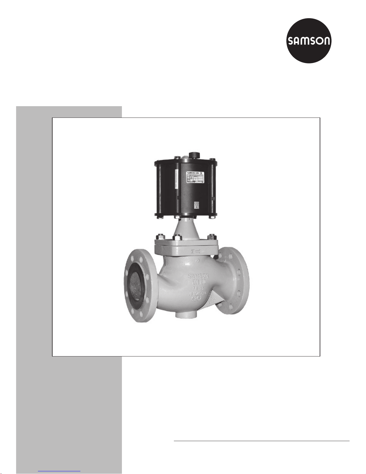
Type3354 Globe Valve
Page 2
2 EB 8140 EN
Note on these mounting and operating instructions
These mounting and operating instructions assist you in mounting and operating the device
safely. The instructions are binding for handling SAMSON devices.
Î For the safe and proper use of these instructions, read them carefully and keep them for
later reference.
Î If you have any questions about these instructions, contact SAMSON‘s After-sales Service
Department (aftersalesservice@samson.de).
The mounting and operating instructions for the devices are included in
the scope of delivery. The latest documentation is available on our website
(www.samson.de) > Product documentation. You can enter the document
number or type number in the [Find:] eld to look for a document.
Denition of signal words
Hazardous situations which, if not avoided,
will result in death or serious injury
Hazardous situations which, if not avoided,
could result in death or serious injury
Property damage message or malfunction
Additional information
Recommended action
DANGER
!
WARNING
!
NOTICE
!
Note
Tip
Page 3

Contents
EB 8140 EN 3
1 Safety instructions and measures ...................................................................5
1.1 Notes on possible severe personal injury .........................................................7
1.2 Notes on possible personal injury ...................................................................7
1.3 Notes on possible property damage ................................................................8
2 Markings on the control valve ........................................................................9
2.1 Valve nameplate ............................................................................................9
3 Design and principle of operation ................................................................10
3.1 Fail-safe action ............................................................................................11
3.2 Technical data .................................................................................................
3.3 Dimensions and weights ...............................................................................12
3.4 Permissible differential pressures ...................................................................13
3.4.1 Version FA/NC with fail-safe position: fail-close .............................................13
3.4.2 Version FE/NO with fail-safe position: fail-open .............................................14
3.5 Accessories .................................................................................................16
4 Measures for preparation ............................................................................16
4.1 Unpacking ..................................................................................................16
4.2 Transporting and lifting ................................................................................16
4.3 Storage .......................................................................................................17
4.4 Preparation for installation ............................................................................17
5 Mounting and start-up ................................................................................. 18
5.1 Installing the valve into the pipeline ...............................................................18
5.1.1 Mounting position ........................................................................................18
5.1.2 Installing the valve ........................................................................................18
5.2 Connecting the signal pressure ......................................................................18
5.3 Additional ttings .........................................................................................19
5.4 Quick check ................................................................................................20
6 Operation ...................................................................................................21
7 Servicing.....................................................................................................22
7.1 Replacing the gaskets ...................................................................................23
7.2 Replacing the packing ..................................................................................24
7.2.1 DN15 to 50 ...............................................................................................24
7.2.2 DN65 and 80.............................................................................................28
Page 4

4 EB 8140 EN
Contents
7.3 Tightening torques ........................................................................................31
7.4 Preparation for return shipment ..................................................................... 31
7.5 Ordering spare parts and operating supplies .................................................32
8 Malfunctions ...............................................................................................33
8.1 Troubleshooting ...........................................................................................33
8.2 Emergency action ........................................................................................34
9 Decommissioning and disassembly ..............................................................35
9.1 Decommissioning .........................................................................................35
9.2 Removing the valve from the pipeline .............................................................35
9.3 Disposal ......................................................................................................35
10 Annex.........................................................................................................36
Page 5

EB 8140 EN 5
Safety instructions and measures
1 Safety instructions and measures
Intended use
The Type3354 Globe Valve is designed for on/off service in process engineering and plants
with industrial requirements. The valve is suitable for liquids, vapors and gases at tempera-
tures from –10 to +180°C and a nominal pressure of PN16. The globe valve is combined
with a pneumatic piston actuator.
The control valve is designed to operate under exactly dened conditions (e.g. operating
pressure, process medium, temperature). Therefore, operators must ensure that the control
valve is only used in applications that meet the specications used for sizing the valve at the
ordering stage. In case operators intend to use the control valve in other applications or con-
ditions than specied, contact SAMSON.
SAMSON does not assume any liability for damage resulting from the failure to use the
valve for its intended purpose or for damage caused by external forces or any other external
factors.
Î Refer to the technical data and nameplate for limits and elds of application as well as
possible uses.
Reasonably foreseeable misuse
The control valve is not suitable for the following applications:
− Use outside the limits dened during sizing and by the technical data
− Use outside the limits dened by the valve accessories mounted on the control valve
Furthermore, the following activities do not comply with the intended use:
− Use of non-original spare parts
− Performing service and repair work not described in these instructions
Qualications of operating personnel
The control valve must be mounted, started up, serviced and repaired by fully trained and
qualied personnel only; the accepted industry codes and practices are to be observed. According to these mounting and operating instructions, trained personnel refers to individuals
who are able to judge the work they are assigned to and recognize possible hazards due to
their specialized training, their knowledge and experience as well as their knowledge of the
applicable standards.
Page 6

6 EB 8140 EN
Safety instructions and measures
Personal protective equipment
We recommend checking the hazards posed by the process medium being used (e.g.
uGESTIS (CLP) hazardous substance database).
Î Provide protective equipment (e.g. safety gloves, eye protection) appropriate for the pro-
cess medium used.
Î Wear hearing protection when working near the valve.
Î Check with the plant operator for details on further protective equipment.
Revisions and other modications
Revisions, conversions or other modications to the product are not authorized by SAMSON.
They are performed at the user's own risk and may lead to safety hazards, for example. Fur-
thermore, the product may no longer meet the requirements for its intended use.
Warning against residual hazards
To avoid personal injury or property damage, plant operators and operating personnel must
prevent hazards that could be caused in the control valve by the process medium, the operating pressure, the signal pressure or by moving parts by taking appropriate precautions. They
must observe all hazard statements, warning and caution notes in these mounting and operating instructions, especially for installation, start-up and service work.
We also recommend checking the hazards posed by the process medium being used (e.g.
uGESTIS (CLP) hazardous substance database).
Î Observe safety measures for handling the device as well as re prevention measures.
Responsibilities of the operator
The operator is responsible for proper operation and compliance with the safety regulations.
Operators are obliged to provide these mounting and operating instructions as well as the
referenced documents to the operating personnel and to instruct them in proper operation.
Furthermore, the operator must ensure that operating personnel or third persons are not exposed to any danger.
Responsibilities of operating personnel
Operating personnel must read and understand these mounting and operating instructions as
well as the referenced documents and observe the hazard statements, warning and caution
notes specied in them. Furthermore, the operating personnel must be familiar with the ap-
plicable health, safety and accident prevention regulations and comply with them.
Page 7

EB 8140 EN 7
Safety instructions and measures
Referenced standards and regulations
The devices comply with the requirements of the European Pressure Equipment Directive
2014/68/EU.
Referenced documentation
The mounting and operating instructions of the mounted valve accessories (e.g. uEB8357
for Type4740 Limit Switch) apply in addition to these mounting and operating instructions.
1.1 Notes on possible severe personal injury
DANGER
!
Risk of bursting in pressure equipment.
Valves and pipelines are pressure equipment. Improper opening can lead to valve
components bursting.
Î Before starting any work on the valve, depressurize all plant sections concerned as
well as the valve.
Î Drain the process medium from all the plant sections concerned as well as the
valve.
Î Wear personal protective equipment.
1.2 Notes on possible personal injury
WARNING
!
Risk of personal injury when the actuator vents.
While the valve is operating, the actuator may vent when the valve opens or closes.
Î Install the control valve in such a way that the actuator does not vent at eye level.
Î Use suitable silencers and vent plugs.
Î Wear eye protection when working in close proximity to the control valve.
Page 8

8 EB 8140 EN
Safety instructions and measures
WARNING
!
Risk of personal injury due to residual process medium in the valve.
While working on the valve, residual process medium can escape and, depending on
its properties, may lead to personal injury, e.g. (chemical) burns.
Î If possible, drain the process medium from all the plant sections concerned and the
valve.
Î Wear protective clothing, safety gloves and eyewear.
Risk of burn injuries due to hot or cold components and pipelines.
Depending on the process medium, valve components, and pipelines may get very hot
or cold and cause burn injuries.
Î Allow components and pipelines to cool down or heat up.
Î Wear protective clothing and safety gloves.
1.3 Notes on possible property damage
NOTICE
!
Risk of valve damage due to contamination (e.g. solid particles) in the pipeline.
The plant operator is responsible for cleaning the pipelines in the plant.
Î Flush the pipelines before start-up.
Î Observe the maximum permissible pressure for valve and plant.
Risk of valve damage due to unsuitable medium properties.
The valve is designed for a process medium with dened properties.
Î Only use the process medium specied for sizing the valve.
Risk of leakage and valve damage due to excessively high or low tightening
torques.
Observe the specied torques on tightening valve components.
Excessively tightened torques lead to parts wearing out quicker. Parts that are too loose
may cause leakage.
Î Observe the specied tightening torques (see section7.3).
Page 9
EB 8140 EN 9
Markings on the control valve
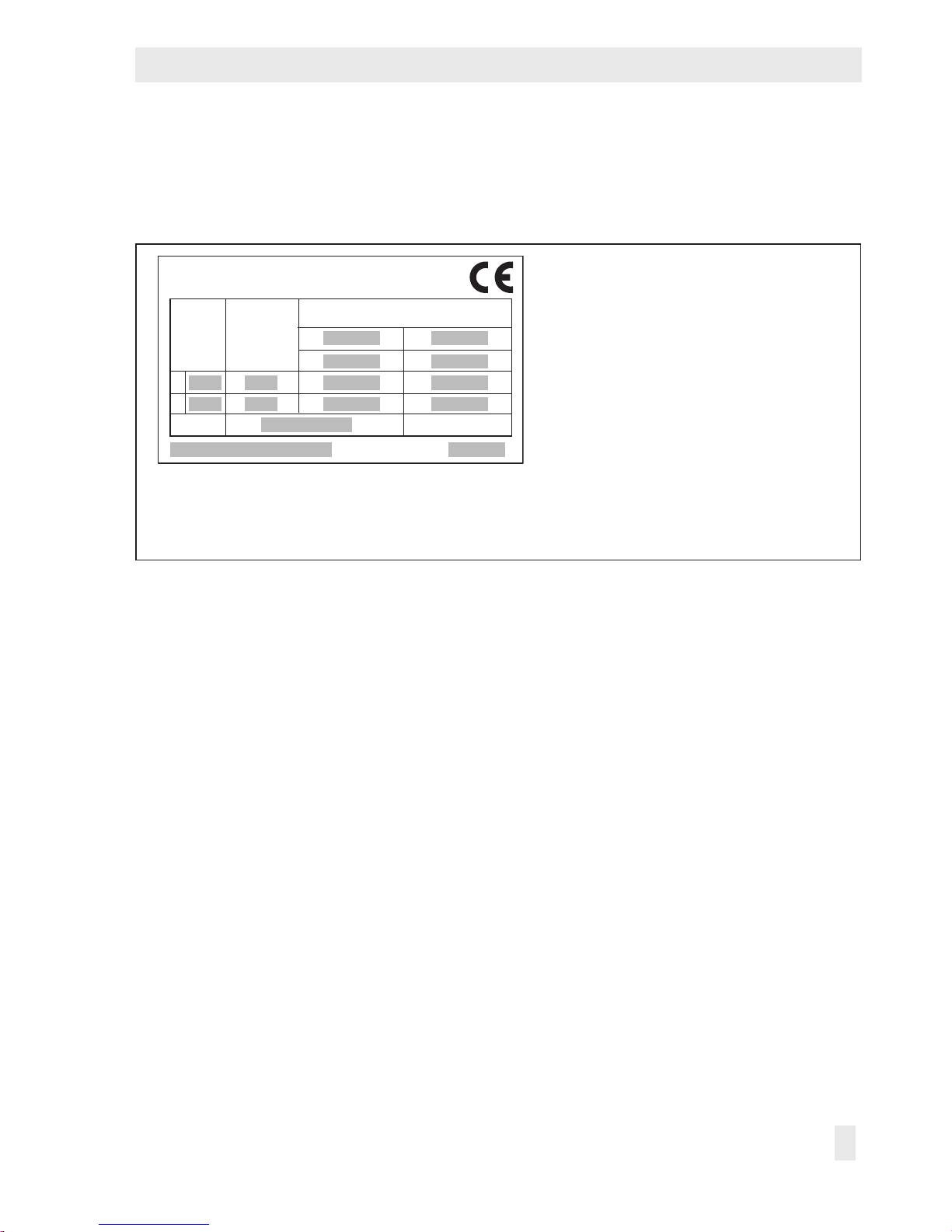
2 Markings on the control valve
2.1 Valve nameplate
1 Actuator area and number of
actuator springs (I or II)
2 Required signal pressure in bar
3 Nominal size (DN and NPS)
4 Max. perm. differential pressure in
bar
5 Conguration ID
6 Max. permissible medium
temperature
7 Year of manufacture
3
3 3
3
4 4
4 4
2
2
5
6 7
1
1
Made in Europe
SAMSON 3354
Stelldruck
Supply
(bar)
Antrieb
Act. size
Max. Diff.druck/pressure ∆p in bar
Fig.1: Nameplate
The nameplate is stuck on the pneumatic actuator.
Page 10
10 EB 8140 EN
Design and principle of operation
3 Design and principle of oper-
ation
The pneumatic control valve consists of a
globe (straight-pattern) valve with a softseated plug and a pneumatic piston
actuator.
The medium ows through the valve in the
direction indicated by the arrow. The signal
pressure applied to the piston actuator determines the position of the plug and thus the
cross-sectional area of ow between the seat
and plug.
The plug/actuator stem (2) is sealed by a
self-adjusting PTFE V-ring packing (4.4) at
13
9
8
S
4.4
4.1
2
3
1
2
4.4
8
9
13
S
FE/NOFA/NC
FE/NOFA/NC
3
1
4.1
1 Body
2 Plug (with plug/actuator
stem)
4.1 Radial shaft seal
4.4 Packing rings
8 Piston
9 Spring
13 Vent plug
S Signal pressure connection
Fig.2: Type3354 Globe Valve · DN15 to 50 (left) · DN65 and 80 (right)
Page 11
EB 8140 EN 11
Design and principle of operation
the valve and by a radial shaft seal (4.1) at
the actuator.
3.1 Fail-safe action
The fail-safe position of the valve upon supply air (signal pressure) failure is determined
by how the piston and actuator spring are
arranged in the pneumatic actuator.
Fail-close (FA/NC)
The actuator spring closes the valve upon air
supply failure. The valve opens when the signal pressure increases.
Fail-open (FE/NO)
The actuator spring opens the valve upon air
supply failure. The valve closes when the signal pressure increases.
3.2 Technical data
The nameplate provides information on the
control valve version (see section2.1). More
information is available in Data Sheet
uT8140.
Table1: Technical data
Valve sizes DN15 to 80
Material Cast iron EN-GJL-250 (EN-JL1040)
Type of connection Flange
Nominal pressure PN 16
Seat-plug seal Soft seal
Characteristic Quick-opening
Compliance
Actuator 30cm² (Ø=63mm) · 60cm² (Ø=90mm) · 120cm² (Ø=125mm)
Permissible signal pressure Minimum à According to section3.4 · Maximum 8bar
Signal pressure connection G¼
Temperature range
Perm. medium temperature –10 to +180°C
Perm. ambient temperature –10 to +60°C
Permissible ow velocity
Max. velocity at the valve
outlet
Liquids: 3m/s · Gases: 0.3Mach
Page 12

12 EB 8140 EN
Design and principle of operation
Table2: Materials
Valve body Cast iron EN-GJL-250 (EN-JL1040)
Intermediate piece 1.0566
Actuator stem 1.4571
Flat plug 1.4571
Seal PTFE, 35% carbon ber reinforced
Packing PTFE/carbon, spring-loaded
Actuator 30/60cm² 120cm²
Actuator cover PA 66, glass ber reinforced Aluminum
Piston PA 66, glass ber reinforced Aluminum
Actuator base
Spheroidal graphite iron
EN-GJS-400-18-LT (EN-JS1049)
Aluminum
Table3: Nominal sizes, valve coefcients and seat diameters
Nominal size DN 15 20 25 32 40 50 65 80
Flow coefcient K
VS
6 9 18 20 36 44 65 90
Seat Ø mm 20 20 24 48 48 48 74 74
Travel mm 15 15 15 15 15 15 15 15
3.3 Dimensions and weights
Version with anges
Nominal size
DN 15 20 25 32 40 50 65
80
Face-to-face dimension L mm 130 150 160 180 200 230 290 310
Height including actuator H mm 235 235 249 249 262 262 368 368
Flange Ød mm 95 105 115 140 150 165 185 200
Valve weight including
actuator
kg 5.4 6.0 7.3 12.3 13.0 15.7 30.5
33.5
Pneumatic piston actuator
Version
Actuator area
(piston Ø)
30cm²
(Ø = 63mm)
60cm² (Ø = 90mm)
120cm²
(Ø = 125mm)
1 spring 2 springs
Housing ØD mm 100 127 180
Signal pressure connection
G¼ G¼
G¼
Page 13

EB 8140 EN 13
Design and principle of operation
∅D
∅
d
H
L
∅
d
H
L
∅D
DN15 to 50 DN65 and 80
3.4 Permissible differential pressures
The specications for the standard version have a dark gray background.
3.4.1 Version FA/NC with fail-safe position: fail-close
Nominal size DN 15 · 20 25 32 · 40 · 50 65 · 80
Actuator
Signal pressure in
bar
Δp
Actuator area
30cm² 5.0 20 10 4 –
60cm²
4.0 16 16 6 –
5.4 – 16 10 –
120cm² 5.8 – – – 10
Page 14

14 EB 8140 EN
Design and principle of operation
3.4.2 Version FE/NO with fail-safe position: fail-open
Required actuators and signal pressures to close the valve at the specied differential pressure. Assigned according to nominal size and actuator area.
Nominal size DN 15 · 20
Control valve DN15/20
60 cm²/Ø90 30 cm²/Ø63
0
345678
2
4
6
8
10
12
14
16
p
[bar]
[bar]
p
perm.
Actuator area
Signal pressure
in bar
Δp
30cm²
(Ø = 63mm)
4 6
5 14
6 16
7 16
8 16
60cm²
(Ø = 90mm)
4 16
Nominal size DN 25
Control valve DN25
60 cm²/Ø90 30 cm²/Ø63
0
345678
2
4
6
8
10
12
14
16
p
[bar]
[bar]
p
perm.
Actuator area
Signal pressure
in bar
Δp
30cm²
(Ø = 63mm)
5 10
6 16
7 16
8 16
60cm²
(Ø = 90mm)
3 11
4 16
7 16
Page 15

EB 8140 EN 15
Design and principle of operation
Nominal size DN 32 · 40 · 50
60 cm²/Ø90 30 cm²/Ø63
0
345678
2
4
6
8
10
12
14
16
p
[bar]
[bar]
p
perm.
Control valve DN32, 40 and 50
Actuator area
Signal pressure
in bar
Δp
30cm²
(Ø = 63mm)
5 2
6 4
7 5
8 7
60cm²
(Ø = 90mm)
3 4
4 7
5 10
6 13
7 16
8 16
Nominal size DN 65 · 80
∆
120 cm²/Ø125
0
345678
2
4
6
8
10
12
14
16
p
[bar]
[bar]
p
perm.
Control valve DN65/80
Actuator area
Signal pressure
in bar
Δp
120cm²
(Ø = 125mm)
3 3
4 6
5 8
6 11
7 14
8 16
Page 16

16 EB 8140 EN
Measures for preparation
3.5 Accessories
− Type4740 Limit Switch with electric mi-
croswitches to indicate valve OPEN or
valve CLOSED for fail-open or fail-close
version, optionally with 3/2-way solenoid valve
− Type4740 Limit Switch with inductive
proximity switches for fail-open or failclose version, optionally with 3/2-way
solenoid valve
− Fixture for holding proximity switches
with M12 thread
− NAMUR adapter to attach a solenoid
valve for valves in DN15 to 50
− 3/2-way solenoid valve with G
1
/
8
for di-
rect attachment to the actuator (double
nipple required for mounting) in DN1½
− 0 to 12bar; 24VDC or 230VAC, op-
tional silencer
− Double nipple G
1
/
8
x G¼ detachable,
brass
− Elbow tting (order no. 8582-2273) for
valves in DN65 and 80
4 Measures for preparation
After receiving the shipment, proceed as follows:
1. Check the scope of delivery. Compare
the shipment received against the delivery note.
2. Check the shipment for transportation
damage. Report any damage to
SAMSON and the forwarding agent
(refer to delivery note).
4.1 Unpacking
Do not remove the packaging until immediately before installing the valve into the pipeline.
Proceed as follows to lift and install the control valve:
1. Remove the packaging from the control
valve.
2. Dispose of the packaging in accordance
with the valid regulations.
4.2 Transporting and lifting
Due to the low service weight, lifting equipment is not required to lift and transport the
control valve (e.g. to install it into the pipeline).
Transport instructions
− Protect the control valve against external
inuences (e.g. impact).
Note
Page 17

EB 8140 EN 17
Measures for preparation
− Do not damage the corrosion protection
(paint, surface coatings). Repair any
damage immediately.
− Protect the control valve against moisture
and dirt.
− Observe the permissible ambient tem-
peratures (see section3.2).
4.3 Storage
Risk of valve damage due to improper storage.
− Observe storage instructions.
− Avoid long storage times.
Contact SAMSON in case of different storage conditions or long storage periods.
We recommend regularly checking the control valve and the prevailing storage conditions during long storage periods.
Storage instructions
− Protect the control valve against external
inuences (e.g. impact).
− Do not damage the corrosion protection
(paint, surface coatings). Repair any
damage immediately.
− Protect the control valve against moisture
and dirt. Store it at a relative humidity of
less than 75%. In damp spaces, prevent
condensation. If necessary, use a drying
agent or heating.
− Make sure that the ambient air is free of
acids or other corrosive media.
− Observe the permissible ambient tem-
peratures (see section3.2).
− Do not place any objects on the control
valve.
4.4 Preparation for installation
Î Flush the pipelines.
The plant operator is responsible for cleaning the pipelines in the plant.
Î Check the valve to make sure it is clean.
Î Check the valve for damage.
Î Check to make sure that the type desig-
nation, valve size, material, pressure rating and temperature range of the valve
match the plant conditions (size and
pressure rating of the pipeline, medium
temperature etc.).
NOTICE
!
Note
Note
Page 18

18 EB 8140 EN
Mounting and start-up
5 Mounting and start-up
The pneumatic control valve is delivered
ready for use.
5.1 Installing the valve into the
pipeline
5.1.1 Mounting position
The control valve may be installed in any position. We recommend installing it in a hori-
zontal pipeline with the actuator pointing
upwards.
Î Choose a place of installation that allows
you to freely access the control valve
even after the entire plant has been com-
pleted.
Î Install the valve in horizontal pipelines.
Î During installation, observe the ow di-
rection through the valve. The arrow on
the valve indicates the direction of ow.
Î Observe the permissible ambient tem-
peratures (see section3.2).
5.1.2 Installing the valve
1. Close the shut-off valve in the pipeline
while the valve is being installed.
2. Remove the protective caps from the
valve ports before installing the valve.
3. Install the valve into the pipeline. Ob-
serve the ow direction through the
valve. The arrow on the valve indicates
the direction of ow.
4. Install the valve free of stress and with the
least amount of vibrations as possible.
5. Depending on the eld of application,
allow the valve to cool down or heat up
to reach ambient temperature before
start up.
6. Slowly open the shut-off valve in the
pipeline after the valve has been installed.
Risk of valve damage due to a sudden pressure increase and resulting high ow velocities.
Slowly open the shut-off valve in the pipeline
during start-up.
5.2 Connecting the signal pres-
sure
Signal pressure connection and venting are
designed as boreholes with a G ¼ female
thread.
The venting hole in valves up to DN50 is tted with a replaceable lter (13.1) with order no. 0550-0213. This lter can be removed by rst unscrewing the vent plug (13).
The signal pressure connection on valves in
DN15 to 50 also allows an adapter plate to
be attached that complies with VDI/
VDE3845 for mounting a solenoid valve.
Î Turn the actuator as required to connect
the signal pressure line.
Î Use the customary ttings for metal or
copper tubing or plastic hoses.
NOTICE
!
Page 19

EB 8140 EN 19
Mounting and start-up
Î Blow through all air pipes and hoses
thoroughly before connecting them.
5.3 Additional ttings
Strainers
We recommend installing a SAMSON
strainer upstream of the valve. It prevents solid particles in the process medium from
damaging the valve.
Additional actuator spring (changing the
spring force)
Fail-close (FA/NC) valves with the nominal
sizes DN40 and 50 (NPS1½ and 2) and
with 60cm² actuators (Ø=90mm) can be
tted with one or two actuator springs
(marked on the nameplate with I or II). See
section2.1.
By adding a spring or removing the internal
spring, the permissible differential pressure
and associated signal pressure can be
changed.
Actua-
tor
Version
Spring
force
Quantity
of
springs
Signal
pressure
60cm² FA/NC
1440N 1 3.8bar
2160N 2 5.4bar
It is not possible to change the fail-safe action.
Note
AUF/Open/OuvertFE/NO/TR
ZU/Close/FermeFA/NC/TS
Fail-open (FE/NO) version
Fail-close (FA/NC) version
Fig.3: Signal pressure connection · DN15 to 50
Page 20

20 EB 8140 EN
Mounting and start-up
5.4 Quick check
Tight shut-off
1. Close the valve.
2. Slowly open the shut-off valve in the
pipeline.
Risk of valve damage due to a sudden pressure increase and resulting high ow velocities.
Slowly open the shut-off valve in the pipeline
during start-up.
3. Check the valve for leakage (visual inspection).
Fail-safe position
Î Shut off the signal pressure line.
Î Check whether the valve moves to the
fail-safe position.
Pressure test
During the pressure test, make sure the following conditions are met:
− Retract the plug stem to open the valve.
− Observe the maximum permissible pres-
sure for valve and plant.
The plant operator is responsible for performing the pressure test. SAMSON's After-sales Service department can support you
to plan and perform a pressure test for your
plant.
NOTICE
!
Note
Page 21

EB 8140 EN 21
Operation
6 Operation
Immediately after completing mounting and
start-up (see section5), the valve is ready for
use.
Risk of personal injury when the actuator
vents.
Wear eye protection when working in close
proximity to the control valve.
Risk of burn injuries due to hot or cold components and pipelines.
Depending on the process medium, valve
components and pipelines may get very hot
or cold and cause burn injuries.
Wear protective clothing and safety gloves.
WARNING
!
WARNING
!
Page 22

22 EB 8140 EN
Servicing
7 Servicing
The control valve is subject to normal wear,
especially at the plug and packing. Depending on the operating conditions, check the
valve at regular intervals to prevent possible
failure before it can occur.
Risk of bursting in pressure equipment.
Valves and pipelines are pressure equipment. Improper opening can lead to valve
components bursting.
− Before starting any work on the valve, de-
pressurize all plant sections concerned as
well as the valve.
− Drain the process medium from all the
plant sections concerned as well as the
valve.
− Wear personal protective equipment.
Risk of personal injury due to residual process medium in the valve.
While working on the valve, residual process
medium can escape and, depending on its
properties, may lead to personal injury, e.g.
(chemical) burns.
− If possible, drain the process medium from
all the plant sections concerned and the
valve.
− Wear protective clothing, safety gloves and
eyewear.
Risk of burn injuries due to hot or cold components and pipelines.
Depending on the process medium, valve
components and pipelines may get very hot
or cold and cause burn injuries.
− Allow components and pipelines to cool
down or heat up.
− Wear protective clothing and safety gloves.
Risk of leakage and valve damage due to
excessively high or low tightening torques.
Observe the specied torques on tightening
valve components.
Excessively tightened torques lead to parts
wearing out quicker. Parts that are too loose
may cause leakage.
Observe the specied tightening torques (see
section7.3).
Risk of control valve damage due to incorrect
service or repair.
Service and repair work must only be performed by trained staff.
The control valve was checked by SAMSON
before it left the factory.
− Certain test results (seat leakage and leak
test) certied by SAMSON lose their
validity when the valve body or actuator
housing is opened.
DANGER
!
WARNING
!
WARNING
!
NOTICE
!
NOTICE
!
Note
Page 23

EB 8140 EN 23
Servicing
− The product warranty becomes void if
service or repair work not described in
these instructions is performed without
prior agreement by SAMSON's After-sales
Service department.
− Only use original spare parts by
SAMSON, which comply with the original
specications.
7.1 Replacing the gaskets
1. Undo the body nuts (1.1) gradually in a
crisscross pattern.
2. Lift the valve bonnet (3) together with the
plug (2) off the body (1).
3. Remove the body gasket (3.1). Carefully
clean the sealing faces in the valve body
and seat bore.
4. Unscrew the countersunk screw (2.1) using a 3mm hex screwdriver, while holding the plug/actuator stem (2) stationary
at the attened part with an open-end
wrench.
5. Remove the PTFE seal (2.2) and plug disk
(2.3). Thoroughly clean the plug disk.
6. Insert a new PTFE seal (2.2).
7. Insert the plug disk (2.3).
8. Tighten the countersunk screw (2.1) using
a 3mm hex screwdriver, while holding
the plug/actuator stem (2) stationary at
the attened part with an open-end
wrench.
9. Insert a new body gasket (3.1).
10. Place the valve bonnet (3) with plug (2)
onto the body (1).
1 Body
1.1 Body nut
2 Plug (with plug/
actuator stem)
2.1 Countersunk screw
2.2 PTFE seal
2.3 Plug disk
3 Valve bonnet
3.1 Body gasket (seal)
2
3
3.1
2.1
2.2
2.3
1.1
1
FE/NOFA/NC
Fig.4: Replacing gaskets · DN15 to 50
Page 24

24 EB 8140 EN
Servicing
11. Tighten the body nuts (1.1) gradually in
a crisscross pattern. Observe tightening
torques.
7.2 Replacing the packing
7.2.1 DN15 to 50
Fail-close (FA)
1. Undo the body nuts (1.1) gradually in a
crisscross pattern.
2. Lift the valve bonnet (3) together with the
plug (2) off the body (1).
3. Undo the screws (6) gradually in a crisscross pattern.
4. Lift off the actuator housing (7).
5. Lift off the spring (9).
6. Remove the travel indicator (10).
7. Use a socket wrench to unscrew the nut
(11) from the plug/actuator stem, while
holding the plug/actuator stem (2) sta-
tionary at the attened part with an
open-end wrench.
8. Remove washer (12), piston (8) together
with the piston ring (8.1) and washer
(9.1).
3.1
2.1
2.2
2.3
1
2
3
1.1
FE/NOFA/NC
1 Body
1.1 Body nut
2 Plug (with plug/
actuator stem)
2.1 Countersunk screw
2.2 PTFE seal
2.3 Plug disk
3 Valve bonnet
3.1 Body gasket (seal)
Fig.5: Replacing gaskets · DN65 and 80
Page 25

EB 8140 EN 25
Servicing
9. Remove the O-ring (8.2) and washer
(8.3) from the plug/actuator stem (2).
10. Unscrew the retaining screw (4.2) at the
side using a 2mm hex screwdriver.
Unscrew the threaded bushing (4) to-
gether with the actuator base (5) from
the valve bonnet (3) using an open-end
wrench (width across ats 41).
11. Press the threaded bushing (4) out of the
actuator base (5). Replace the slip washers (5.2) with new ones.
12. Pull the actuator/plug stem (2) down out
of the valve bonnet (3).
13. Pull all the packing parts out of the packing chamber using a suitable tool. Clean
the packing chamber thoroughly. Renew
the packing.
14. Slide the plug/actuator stem (2) into the
valve bonnet (3).
15. Carefully slide the packing parts over the
plug/actuator stem into the packing
chamber using a suitable tool. Keep the
correct sequence:
− Spring (4.5)
− Washer (4.3)
− V-ring packing (4.4)
16. Place the top slip washer (5.2) into the
actuator base (5).
17. Push the threaded bushing (4) into the
actuator base (5). Make sure that the
O-ring (5.3) is correctly seated in the
threaded bushing.
18. Place the bottom slip washer (5.2) on the
valve bonnet (3).
19. Screw the threaded bushing (4) together
with the actuator base (5) over the plug/
actuator stem (2) onto the valve bonnet
(3).
Tighten the threaded bushing only to the
point where the actuator base (5) can
still rotate on the slip washers (5.2).
20. Screw tight the retaining screw (4.2) at
the side to x the threaded bushing in
place.
21. Slide the washer (8.3) and O-ring (8.2)
onto the plug/actuator stem (2).
22. Place on the piston (8) with piston ring
(8.1) and washer (12).
23. Insert the washer (9.1) and spring (9) into the piston (8).
24. Tighten the nut (11) intended for fastening the piston, while holding the plug/
actuator stem (2) stationary at the attened part with an open-end wrench.
25. Fasten the travel indicator (10).
26. Put on actuator housing (7) and fasten it
tight onto the actuator base (5) by tightening the screws (6) gradually in a crisscross pattern.
27. Replace the body gasket (3.1). See sec-
tion7.1.
28. Place the valve bonnet (3) with plug (2)
onto the body (1).
29. Tighten the body nuts (1.1) gradually in
a crisscross pattern. Observe tightening
torques.
Page 26

26 EB 8140 EN
Servicing
1
2
3
4
3.1
3.2
4.1
4.2
4.3
4.4
4.5
5
5.2
5.3
10
7
8
11
12
8.1
8.3
9
13
13.1
S
5.1
7.1
9.1
6
8.2
FE/NOFA/NC
1.1
1 Body
1.1 Body nut
2 Plug (with plug/
actuator stem)
3 Valve bonnet
3.1 Body gasket (seal)
3.2 Borehole
4 Threaded bushing
4.1 Radial shaft seal
4.2 Retaining screw
4.3 Washer
4.4 Packing rings
4.5 Spring
5 Actuator base
5.1 O-ring
5.2 Washer
5.3 O-ring
6 Screw
7 Actuator housing
7.1 Dome
8 Piston
8.1 Piston ring
8.2 O-ring
8.3 Washer
9 Spring
9.1 Washer
10 Travel indicator
11 Nut
12 Washer
13 Vent plug
13.1
Filter
S Signal pressure
connection
Fig.6: Replacing the packing · DN15 to 50
Page 27

EB 8140 EN 27
Servicing
Fail-open (FE)
1. Undo the body nuts (1.1) gradually in a
crisscross pattern.
2. Lift the valve bonnet (3) together with the
plug (2) off the body (1).
3. Undo the screws (6) gradually in a crisscross pattern.
4. Lift off the actuator housing (7).
5. Use a socket wrench to unscrew the nut
(11) from the plug/actuator stem, while
holding the plug/actuator stem (2) sta-
tionary at the attened part with an
open-end wrench.
6. Remove washer (12), piston (8) together
with the piston ring (8.1) and washer
(9.1).
7. Remove the O-ring (8.2) and washer
(8.3) from the plug/actuator stem (2).
8. Lift off the spring (9).
9. Remove the travel indicator (10).
10. Unscrew the retaining screw (4.2) at the
side using a 2mm hex screwdriver.
Unscrew the threaded bushing (4) to-
gether with the actuator base (5) from
the valve bonnet (3) using an open-end
wrench (width across ats 24).
11. Press the threaded bushing (4) out of the
actuator base (5). Replace the slip washers (5.2) with new ones.
12. Pull the actuator/plug stem (2) down out
of the valve bonnet (3).
13. Pull all the packing parts out of the packing chamber using a suitable tool. Clean
the packing chamber thoroughly. Renew
the packing.
14. Slide the plug/actuator stem (2) into the
valve bonnet (3).
15. Carefully slide the packing parts over the
plug/actuator stem into the packing
chamber using a suitable tool. Keep the
correct sequence:
− Spring (4.5)
− Washer (4.3)
− V-ring packing (4.4)
16. Place the top slip washer (5.2) into the
actuator base (5).
17. Push the threaded bushing (4) into the
actuator base (5). Make sure that the
O-ring (5.3) is correctly seated in the
threaded bushing.
18. Place the bottom slip washer (5.2) on the
valve bonnet (3).
19. Screw the threaded bushing (4) together
with the actuator base (5) over the plug/
actuator stem (2) onto the valve bonnet
(3).
Tighten the threaded bushing only to the
point where the actuator base (5) can
still rotate on the slip washers (5.2).
20. Screw tight the retaining screw (4.2) at
the side to x the threaded bushing in
place.
21. Slide the washer (8.3) onto the plug/actuator stem (2).
22. Place the spring (9) together with the
washer (9.1) onto the actuator base (5).
Page 28

28 EB 8140 EN
Servicing
23. Slide the piston (8) with piston ring (8.1)
over the plug/actuator stem (2).
24. Place on the O-ring (8.2) and washer
(12).
25. Tighten the nut (11) intended for fastening the piston, while holding the plug/
actuator stem (2) stationary at the attened part with an open-end wrench.
26. Fasten the travel indicator (10).
27. Put on actuator housing (7) and fasten it
tight onto the actuator base (5) by tightening the screws (6) gradually in a crisscross pattern.
28. Replace the body gasket (3.1). See sec-
tion7.1.
29. Place the valve bonnet (3) with plug (2)
onto the body (1).
30. Tighten the body nuts (1.1) gradually in
a crisscross pattern. Observe tightening
torques.
7.2.2 DN65 and 80
Fail-close (FA/NC)
1. Undo the body nuts (1.1) gradually in a
crisscross pattern.
2. Lift the valve bonnet (3) together with the
plug (2) off the body (1).
3. Undo the top screws (6) gradually in a
crisscross pattern.
4. Lift off the dome (7.1) and actuator housing (7).
5. Lift off the spring (9).
6. Remove the travel indicator (10).
7. Use a socket wrench to unscrew the nut
(11) from the plug/actuator stem, while
holding the plug/actuator stem (2) sta-
tionary at the attened part with an
open-end wrench.
8. Remove the washer (12), piston (8) and
piston ring (8.1).
9. Remove the O-ring (8.2) and washer
(8.3) from the plug/actuator stem (2).
10. Unscrew the retaining screw (4.2) at the
side using a 2mm hex screwdriver.
11. Unscrew the threaded bushing (4) together with the actuator base (5) from
the valve bonnet (3) using an open-end
wrench (width across ats 41).
12. Press the threaded bushing (4) out of the
actuator base (5). Replace the slip washers (5.2) with new ones.
13. Pull the actuator/plug stem (2) down out
of the valve bonnet (3).
14. Pull all the packing parts out of the packing chamber using a suitable tool. Clean
the packing chamber thoroughly. Renew
the packing.
15. Slide the plug/actuator stem (2) into the
valve bonnet (3).
16. Carefully slide the packing parts over the
plug/actuator stem into the packing
chamber using a suitable tool. Keep the
correct sequence:
− Spring (4.5)
− Washer (4.3)
− V-ring packing (4.4)
17. Place the top slip washer (5.2) into the
actuator base (5).
Page 29

EB 8140 EN 29
Servicing
1
9
5.1
7
8
11
12
13
2
3.1
3
4.5
4.3
4.4
3.2
5.2
4
4.2
S
6
5
8.1
8
4.1
8.3
8.2
8.1
10
7.1
FE/NOFA/NC
5.3
1.1
1 Body
1.1
Body nut
2 Plug (with plug/
actuator stem)
3 Valve bonnet
3.1
Body gasket (seal)
3.2
Borehole
4 Threaded bushing
4.1
Radial shaft seal
4.2
Retaining screw
4.3
Washer
4.4
Packing rings
4.5
Spring
5 Actuator base
5.1
O-ring
5.2
Washer
5.3
O-ring
6 Screw
7 Actuator housing
7.1
Dome
8 Piston
8.1
Piston ring
8.2
O-ring
8.3
Washer
9 Spring
9.1
Washer
10 Travel indicator
11 Nut
12 Washer
13 Vent plug
S Signal pressure
connection
Fig.7: Replacing the packing · DN65 and 80
Page 30

30 EB 8140 EN
Servicing
18. Push the threaded bushing (4) into the
actuator base (5). Make sure that the
O-ring (5.3) is correctly seated in the
threaded bushing.
19. Place the bottom slip washer (5.2) on the
valve bonnet (3).
20. Screw the threaded bushing (4) together
with the actuator base (5) over the plug/
actuator stem (2) onto the valve bonnet
(3).
Tighten the threaded bushing only to the
point where the actuator base (5) can
still rotate on the slip washers (5.2).
21. Screw tight the retaining screw (4.2) at
the side to x the threaded bushing in
place.
22. Slide the washer (8.3) and O-ring (8.2)
onto the plug/actuator stem (2).
23. Place on the piston (8) with piston ring
(8.1) and washer (12).
24. Insert the spring (9) into the piston (8).
25. Tighten the nut (11) intended for fastening the piston, while holding the plug/
actuator stem (2) stationary at the attened part with an open-end wrench.
26. Fasten the travel indicator (10).
27. Put on actuator housing (7) and dome
(7.1) and fasten them tight onto the actuator base (5) by tightening the top
screws (6) gradually in a crisscross pattern.
28. Replace the body gasket (3.1). See sec-
tion7.1.
29. Place the valve bonnet (3) with plug (2)
onto the body (1).
30. Tighten the body nuts (1.1) gradually in
a crisscross pattern. Observe tightening
torques.
Fail-open (FE/NO)
1. Undo the body nuts (1.1) gradually in a
crisscross pattern.
2. Lift the valve bonnet (3) together with the
plug (2) off the body (1).
3. Undo the top screws (6) gradually in a
crisscross pattern.
4. Lift off the dome (7.1) and actuator housing (7).
5. Use a socket wrench to unscrew the nut
(11) from the plug/actuator stem, while
holding the plug/actuator stem (2) sta-
tionary at the attened part with an
open-end wrench.
6. Remove the washer (12), piston (8) and
piston ring (8.1).
7. Remove the O-ring (8.2) and washer
(8.3) from the plug/actuator stem (2).
8. Lift off the spring (9).
9. Remove the travel indicator (10).
10. Unscrew the retaining screw (4.2) at the
side using a 2mm hex screwdriver.
11. Unscrew the threaded bushing (4) together with the actuator base (5) from
the valve bonnet (3) using an open-end
wrench (width across ats 41).
12. Press the threaded bushing (4) out of the
actuator base (5). Replace the slip washers (5.2) with new ones.
13. Pull the actuator/plug stem (2) down out
of the valve bonnet (3).
Page 31

EB 8140 EN 31
Servicing
14. Pull all the packing parts out of the packing chamber using a suitable tool. Clean
the packing chamber thoroughly. Renew
the packing.
15. Slide the plug/actuator stem (2) into the
valve bonnet (3).
16. Carefully slide the packing parts over the
plug/actuator stem into the packing
chamber using a suitable tool. Keep the
correct sequence:
− Spring (4.5)
− Washer (4.3)
− V-ring packing (4.4)
17. Place the top slip washer (5.2) into the
actuator base (5).
18. Push the threaded bushing (4) into the
actuator base (5). Make sure that the
O-ring (5.3) is correctly seated in the
threaded bushing.
19. Place the bottom slip washer (5.2) on the
valve bonnet (3).
20. Screw the threaded bushing (4) together
with the actuator base (5) over the plug/
actuator stem (2) onto the valve bonnet
(3).
Tighten the threaded bushing only to the
point where the actuator base (5) can
still rotate on the slip washers (5.2).
21. Screw tight the retaining screw (4.2) at
the side to x the threaded bushing in
place.
22. Place the spring (9) together with the
washer (9.1) onto the actuator base (5).
23. Slide the piston (8) with piston ring (8.1)
over the plug/actuator stem (2).
24. Place on the O-ring (8.2) and washer
(12).
25. Tighten the nut (11) intended for fastening the piston, while holding the plug/
actuator stem (2) stationary at the attened part with an open-end wrench.
26. Fasten the travel indicator (10).
27. Put on actuator housing (7) and dome
(7.1) and fasten them tight onto the actuator base (5) by tightening the top
screws (6) gradually in a crisscross pattern.
28. Replace the body gasket (3.1). See sec-
tion7.1.
29. Place the valve bonnet (3) with plug (2)
onto the body (1).
30. Tighten the body nuts (1.1) gradually in
a crisscross pattern. Observe tightening
torques.
7.3 Tightening torques
Table4: Tightening torques for body nuts
(1.1)
Valve size Tightening torque
DN15 to 25 (M10) 30Nm
DN32 to 50 (M12) 50Nm
DN65 and 80 (M16) 100Nm
Page 32

32 EB 8140 EN
Servicing
7.4 Preparation for return shipment
Proceed as follows to return devices to
SAMSON:
1. Put the control valve out of operation (see
section9).
2. Decontaminate the valve. Remove any
residual process medium.
3. Fill in the Declaration on Contamination,
which can be downloaded from our
website at uwww.samson.de > Services
> Check lists for after sales service >
Declaration on Contamination.
4. Send the valve together with the lled-in
form to your nearest SAMSON subsidiary. SAMSON subsidiaries are listed on
our website at uwww.samson.de >
Contact.
7.5 Ordering spare parts and
operating supplies
Contact your nearest SAMSON subsidiary
or the SAMSON After-sales Service department for information on spare parts, lubricants and tools.
Page 33

EB 8140 EN 33
Malfunctions
8 Malfunctions
Depending on the operating conditions, check the valve at certain intervals to prevent possible failure before it can occur. Operators are responsible for drawing up an inspection plan.
SAMSON's After-sales Service department can support you to draw up an inspection plan
for your plant.
8.1 Troubleshooting
Malfunction Possible reasons Recommended action
Plug/actuator stem does not
move on demand.
Actuator is blocked. Check attachment.
Unblock the actuator.
Signal pressure too low Check the signal pressure.
Check the signal pressure line
for leakage.
Plug/actuator stem does not
move through the whole range.
Signal pressure too low Check the signal pressure.
Check the signal pressure line
for leakage.
The valve leaks to the atmosphere (fugitive emissions).
The packing is defective. Replace packing (see sec-
tion7.2) or contact SAMSON's
After-sales Service department.
Increased ow through closed
valve (seat leakage)
Dirt or other foreign particles
deposited between the seat and
plug.
Shut off the section of the pipe-
line and ush the valve.
Valve trim is worn. Contact SAMSON's After-sales
Service department.
Contact SAMSON's After-sales Service department for malfunctions not listed in the table.
Tip
Note
Page 34

34 EB 8140 EN
Servicing
8.2 Emergency action
Upon supply air or control signal failure, the
valve moves to its fail-safe position (see sec-
tion3.1).
The plant operator is responsible for emergency action to be taken in the plant.
In the event of a valve malfunction:
1. Close the shut-off valves upstream and
downstream of the control valve to stop
the process medium from owing
through the valve.
2. Check the valve for damage. If
necessary, contact SAMSON's Aftersales Service department.
Putting the valve back into operation after
a malfunction
Î Slowly open the shut-off valves. Allow
the process medium to slowly ow into
the valve.
Page 35

EB 8140 EN 35
Decommissioning and disassembly
9 Decommissioning and
disassembly
Risk of bursting in pressure equipment.
Valves and pipelines are pressure equipment. Improper opening can lead to valve
components bursting.
− Before starting any work on the valve, de-
pressurize all plant sections concerned as
well as the valve.
− Drain the process medium from all the
plant sections concerned as well as the
valve.
− Wear personal protective equipment.
Risk of personal injury due to residual process medium in the valve.
While working on the valve, residual process
medium can escape and, depending on its
properties, may lead to personal injury, e.g.
(chemical) burns.
Wear protective clothing, safety gloves and
eyewear.
Risk of burn injuries due to hot or cold components and pipeline.
Valve components and the pipeline may become very hot or cold. Risk of burn injuries.
− Allow components and pipelines to cool
down or heat up.
− Wear protective clothing and safety gloves.
9.1 Decommissioning
1. Close the shut-off valve in the pipeline.
2. Completely drain the pipelines and
valve.
3. Depressurize the plant.
4. If necessary, allow the pipeline and valve
components to cool down or heat up.
9.2 Removing the valve from
the pipeline
1. Put the control valve out of operation (see
section9.1).
2. Unbolt the ange joint.
3. Remove the valve from the pipeline.
9.3 Disposal
Î Observe local, national and international
refuse regulations.
Î Do not dispose of components, lubricants
and hazardous substances together with
your other household waste.
DANGER
!
WARNING
!
WARNING
!
Page 36

36 EB 8140 EN
Annex
10 Annex
After-sales Service
You can reach the After-sales Service Department at aftersalesservice@samson.de.
Addresses of SAMSONAG and its subsidiaries
The addresses of SAMSON AG, its
subsidiaries, representatives and service
facilities worldwide can be found on the
SAMSON website (uwww.samson.de) or in
all SAMSON product catalogs.
Required specications
Please submit the following details:
− Order number and position number in
the order
− Type, model number, nominal size and
valve version
− Pressure and temperature of the process
medium
− Flow rate in m³/h
− Supply pressure of the actuator
− Installation drawing
Page 37

EB 8140 EN 37
Page 38

38 EB 8140 EN
Page 39

EB 8140 EN 39
Page 40

SAMSON AG · MESS- UND REGELTECHNIK
Weismüllerstraße 3 · 60314 Frankfurt am Main, Germany
Phone: +49 69 4009-0 · Fax: +49 69 4009-1507
samson@samson.de · www.samson.de
EB 8140 EN
2017-11-29 · English
 Loading...