

Page 1
Translation of original instructions
EB 8097 EN
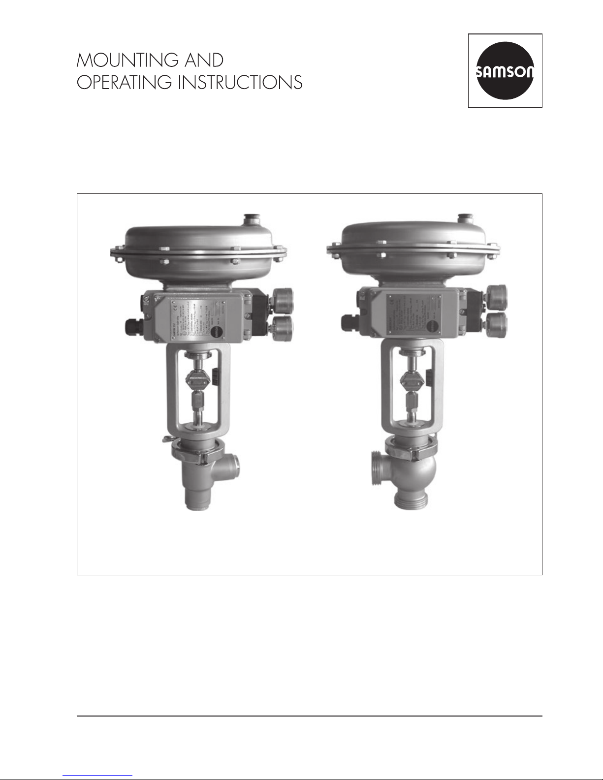
Type3347-7, cast body with welding
ends
Type3347-7, bar stock body with
threaded connections
Edition May 2016
Type3347-1 and Type3347-7 Pneumatic Control Valves
Page 2
Note on these mounting and operating instructions
These mounting and operating instructions assist you in mounting and operating the device
safely. The instructions are binding for handling SAMSON devices.
Î For the safe and proper use of these instructions, read them carefully and keep them for
later reference.
Î If you have any questions about these instructions, contact SAMSON‘s After-sales Service
Department (aftersalesservice@samson.de).
The mounting and operating instructions for the devices are included in
the scope of delivery. The latest documentation is available on our website
at www.samson.de > Service & Support > Downloads > Documentation.
Denition of signal words
Hazardous situations which, if not avoided,
will result in death or serious injury
Hazardous situations which, if not avoided,
could result in death or serious injury
Property damage message or malfunction
Additional information
Recommended action
DANGER
!
WARNING
!
NOTICE
!
Note
Tip
2 EB 8097 EN
Page 3

Contents
EB 8097 EN 3
1 General safety instructions .............................................................................4
2 Design and principle of operation ..................................................................6
3 Assembling valve and actuator ......................................................................9
3.1 Assembly and adjustment ...............................................................................9
3.2 Option of preloading springs for "actuator stem extends"................................10
3.3 Different rated travels of valve and actuator ...................................................10
4 Installation ..................................................................................................11
4.1 Notes on installation ....................................................................................11
4.2 Signal pressure line ......................................................................................11
5 Operation ...................................................................................................11
6 Maintenance ...............................................................................................12
6.1 Replacing sealing parts and plug ..................................................................12
7 Description of nameplates ............................................................................14
8 Inquiries .....................................................................................................15
Page 4

4 EB 8097 EN
General safety instructions
1 General safety instructions
− The control valve must be mounted, started up, or serviced by fully trained
and qualied personnel only; the accepted industry codes and practices
are to be observed. Make sure employees or third persons are not exposed to any danger. All safety instructions and warnings given in these
mounting and operating instructions, particularly those concerning installation, start-up and maintenance, must be strictly observed.
− The control valves comply with the requirements of the European Pressure
Equipment Directive 2014/68/EU. Valves with a CE marking have a
declaration of conformity which includes information about the applied
conformity assessment procedure.
The declaration of conformity can be viewed and downloaded at
http://www.samson.de.
− To ensure appropriate use, only use the valve in applications where the op-
erating pressure and temperatures do not exceed the specications used
for sizing the valve at the ordering stage. The manufacturer does not assume any responsibility for damage caused by external forces or any other
external factors.
− Any hazards that could be caused in the valve by the process medium, the
operating pressure, the signal pressure or by moving parts are to be prevented by taking appropriate precautions.
− Proper shipping and storage are assumed.
− For installation and maintenance, make sure the relevant section of the
pipeline is depressurized and, depending on the process medium, drained
as well. Depending on the eld of application, allow the valve to cool
down or heat up to reach ambient temperature before starting any work
on it.
− When working on the valve, make sure that the pneumatic air supply as
well as the control signal are disconnected to prevent any hazards caused
by moving parts.
− Be particularly careful if the actuator springs are preloaded. Such actua-
tors are labeled correspondingly and can also be identied by three long
bolts protruding from the bottom of the actuator. Before starting any work
on the valve, relieve the compression from the preloaded springs.
Page 5

EB 8097 EN 5
General safety instructions
According to the ignition risk assessment performed in accordance with EN13463-1:2009,
section 5.2, the non-electrical control valves do not have their own potential ignition source
even in the rare incident of an operating fault. As a result, they do not fall within the scope of
Directive 2014/34/EU.
Î For connection to the equipotential bonding system, observe the requirements specied in
section 6.4 of EN60079-14 (VDE0165 Part 1).
Page 6

6 EB 8097 EN
Design and principle of operation
2 Design and principle of oper-
ation
The Type3347 Angle Valve can be combined with either a Type3271 Pneumatic
Actuator or a Type3277 Pneumatic Actuator
with integral positioner attachment.
The standard valve body is designed for
welding into pipelines. Other versions can
be equipped with threaded or anged ends,
or clamp connections.
The control valve is tted with an easily detachable clamp connection between valve
body and bonnet. The body free of dead
space is suitable for CIP (Cleaning-In-Place).
The control valves are mainly designed for
use as control or on/off valves in the food
industry.
The medium ows through the valve in the
direction indicated by the arrow. The plug
(3) is moved by changing the signal pressure
acting on the diaphragm of the actuator.
The plug stem (6) with plug (3) and actuator
stem (8.1) are connected by the stem connector (7) and sealed by a PTFE seals (5.1
and 5.3).
In the special version with steam line connection, an additional spring-loaded PTFE ring
packing (4.2) is used. In this case, the plug
stem can be cleaned through the connection
of a steam line.
Fail-safe position
Depending on how the compression
springs(8.3) are arranged in the actuator,
the valve has two different fail-safe positions:
− Actuator stem extends: when the signal
pressure is reduced or the air supply
fails, the springs move the actuator stem
downward and close the valve.
The valve opens when the signal pressure
is increased enough to overcome the
force exerted by the springs.
− Actuator stem retracts: when the signal
pressure is reduced or the air supply
fails, the springs move the actuator stem
upward and open the valve.
The valve closes when the signal pressure
is increased enough to overcome the
force exerted by the springs.
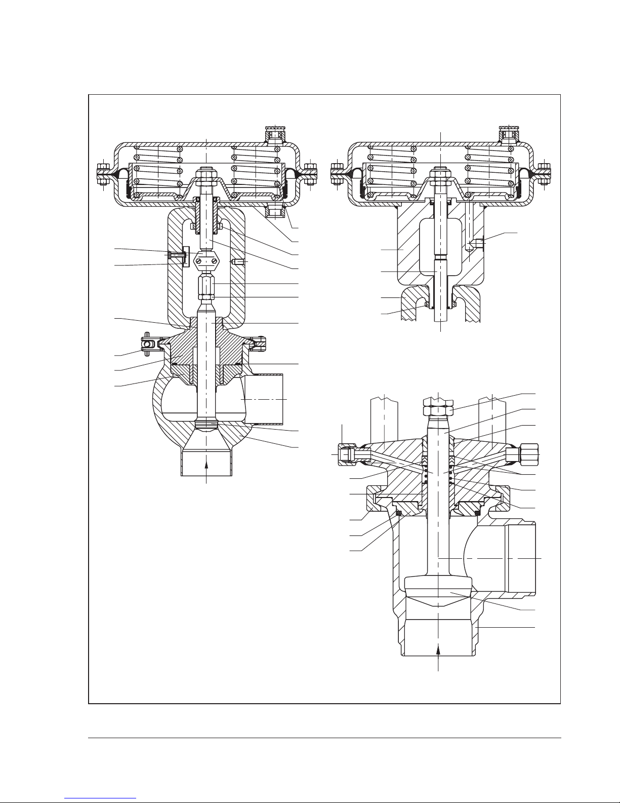
Legend for Fig.1
1 Valve body
1.1 Centering ring
1.2 Body gasket
1.3 Compensating ring
3 Plug
4.1 Spring (special version)
4.2 Packing (special version)
4.3 Washers (special version)
5 Valve bonnet
5.1 Stem seal
5.2 Body and stem seal
5.3 Wiper ring
5.4 Clamp
5.5 Travel indicator scale
6 Plug stem
6.1 Stem connector nut
6.2 Lock nut
7 Stem connector
8 Actuator
8.1 Actuator stem
8.2 Ring nut
8.3 Compression springs
9 Signal pressure
connection
10 Compression-type tting
Page 7
EB 8097 EN 7
Design and principle of operation
6.1
6.2
6
1.3
8
8.3
8.2
8.1
5.5
7
5
5.3
5.4
5.2
3
1
9
8
8.1
5
8.2
10
4.2
5.1
5.4
1.2
1.1
4.3
6.2
6
5.3
4.1
4.3
3
1
Special version with steam line connection
Version with cast body
Type3277 ActuatorType3271 Actuator
Fig.1: Sectional drawings
Page 8

8 EB 8097 EN
Design and principle of operation
Compliance
The Type3347 Valve bears the EAC mark of
conformity:
Page 9

EB 8097 EN 9
Assembling valve and actuator
3 Assembling valve and actua-
tor
The basic pneumatic actuator can be replaced by a pneumatic actuator with additional handwheel or by an electric actuator.
The standard pneumatic actuator can be replaced by a smaller or larger actuator for all
nominal valve sizes.
If the travel range of the actuator is larger
than the travel of the valve, the springs in the
actuator are preloaded by SAMSON so that
the travel ranges match.
3.1 Assembly and adjustment
Proceed as follows if the valve and actuator
have not been assembled by SAMSON or if
the actuator is to be replaced by an actuator
of another type or size:
1. Loosen the lock nut (6.2) and stem connector nut (6.1) on the valve. Firmly
press the plug together with the plug
stem into the seat. Thread down the lock
nut and stem connector nut.
2. Remove the clamps of the stem connector
(7) and the ring nut (8.2) from the actuator (8).
3. Slide the ring nut over the plug stem.
4. Place the actuator onto the valve bonnet
(5) and secure it with the ring nut (8.2).
5. Read the bench range (e.g.0.2 to 1bar)
and the actuator's fail-safe action (e.g.
"actuator stem extends") from the actuator's nameplate.
The fail-safe action "actuator stem extends" or "actuator stem retracts" is
marked by FA or FE on the Type3271
Actuator, and by a corresponding symbol on the nameplate of the Type3277
Actuator.
The lower value corresponds to the lower
bench range value to be adjusted,
whereas the upper value corresponds the
upper bench range value.
During assembly, make sure that the stem
seal (5.1) is not damaged.
The maximum possible actuator travel must
not exceed the maximum permissible valve
travel (see adhesive label on the yoke).
6. For actuators with "actuator stem extends" fail-safe action, apply a signal
pressure that corresponds to the lower
bench range value (e.g. 0.2 or 0.4bar)
to the connection on the bottom diaphragm chamber.
For actuators with "actuator stem retracts" fail-safe action, apply a signal
pressure that corresponds to the upper
bench range value (e.g. 1bar) to the
connection on the top diaphragm chamber.
7. Screw on the stem connector nut (6.1) by
hand until it touches the actuator stem
(8.1). Turn it a further ¼turn and secure
this position with the lock nut (6.2)
8. Position clamps of the stem connector (7)
and screw them tight.
NOTICE
!
Page 10
10 EB 8097 EN
Assembling valve and actuator
9. Align travel indicator scale (5.5) with the
tip of the stem connector; for actuators
with fail-safe action "actuator stem extends" align it with lower marking (valve
closed) and for actuators with fail-safe
action "actuator stem retracts" align it
with top marking (valve open).
Note on removing an actuator
When removing an actuator with "stem extends" fail-safe action from a valve and especially an actuator with preloaded springs,
apply a signal pressure that is slightly higher
than the lower bench range value (see actuator nameplate) to the lower signal pressure
connection to allow the ring nut (8) to be
loosened.
3.2 Option of preloading
springs for "actuator stem
extends"
To achieve a greater positioning force, the
springs of the actuators can be preloaded by
up to 25% of their travel or their bench
range.
When a preload of, e.g. 0.1bar, is desired
for a bench range of0.2 to 1bar, the lower
bench range value is shifted by 0.1bar to
0.3bar (0.1bar correspond to a preload of
12.5%).
When adjusting the valve, set the lower
bench range value to 0.3bar. Write the new
bench range with preloaded springs of 0.3
to 1.1bar on the nameplate.
3.3 Different rated travels of
valve and actuator
Actuators that have already been preloaded
by the manufacturer without mounting the
valve are labeled correspondingly. Addition-
ally, they can be identied by three longer
bolts with nuts protruding from the bottom
diaphragm case.
Always use actuators with preloaded springs
when the valve's rated travel is smaller than
the rated travel of the actuator.
GEFAHR
!
WARNING
!
NOTICE
!
Page 11

EB 8097 EN 11
Installation
4 Installation
4.1 Notes on installation
− The valve must be installed in the upright
position with the actuator on top.
For valves with welding ends, after loosening
the clamp (5.4), remove the entire valve construction from the valve body before welding
it into the pipeline.
− Make sure the valves are installed free of
stress. Check to ensure the plug stem
moves smoothly.
− Flush the pipeline thoroughly before in-
stalling the valve.
− If the valve bonnet is designed for con-
nection to a steam line, connect the compression-type ttings to the steam supply
line.
A pressure in the steam line connection
(steam or sterile uid) that is higher than the
pressure in the valve itself may affect the
process medium inside the valve due to it be
mixed with the steam (or sterile uid).
Observe the relevant hygiene regulations.
For compliance with 3-A regulations, a
gasket according to the recommendations of
the 3-ASanitary Standards Inc.
(uBulletin2011-3 at
uhttp://www.3-a.org) is required for a
Type3347 Valve with threaded connections
according to DIN11851/DIN11887.
4.2 Signal pressure line
Connect the signal pressure line for valves
with actuator with fail-safe action "actuator
stem extends" to the connection on the bottom diaphragm case, and for valves with actuator with fail-safe action "actuator stem retracts" to the connection on the top diaphragm case.
In the Type3277 Actuator, the lower signal
pressure connection is located at the side of
the yoke under the bottom diaphragm case.
5 Operation
The actuator's direction of action can be reversed, if required. Refer to the mounting
and operating instructions of the pneumatic
actuator:
uEB8310-X for Type3271 and Type3277
NOTICE
!
NOTICE
!
Note
Page 12

12 EB 8097 EN
Maintenance
6 Maintenance
If the valve leaks, the wiper (5.3), steam seal
(5.1), or PTFE V-ring packing (4.2) (in the
version with steam line connection) might be
defective.
If the valve does not close tightly, tight shutoff may be impaired by dirt stuck between
the seat and plug or by damaged facings.
We recommend removing the parts, cleaning
them, and, if necessary, replacing them with
new ones.
− Before performing any work on the control
valve, make sure the relevant plant section
has been depressurized and, depending
on the process medium, drained as well.
− When used at high temperatures, allow the
plant section to cool down to ambient temperature.
− As valves are not free of cavities, remem-
ber that residual process medium might still
be contained in the valve. We recommend
removing the valve from the pipeline or the
entire valve construction when the valve is
welded into the pipeline.
− Before starting any work on the valve
body, disconnect the signal pressure and
remove the signal pressure line as well as
the actuator.
− During disassembly or assembly of the
valve, make sure that the stem seal (5.1) is
not damaged. The plug must not be moved
beyond the valve travel.
6.1 Replacing sealing parts
and plug
Before starting any work on the valve body,
remove the actuator from the valve.
1. Apply a signal pressure that is higher
than the lower bench range value to the
actuator (see nameplate).
2. Remove the stem connector clamps (7)
between the actuator stem and the plug
stem and unscrew the ring nut (8.2).
3. Lift the actuator off the valve.
4. Remove nuts (6.1 and 6.2).
5. Remove the clamp (5.4). Remove the
valve bonnet (5) together with plug (3)
and centering ring (1.1).
6. Pull the plug out of the valve bonnet.
Make sure that the stem seal (5.1) is not
damaged.
7. Use a suitable tool to force out damaged
parts, e.g. wiper (5.3) and stem seal
(5.1).
In version with steam line connection, also remove packing (4.2), washer (4.3),
and spring (4.1). Clean the packing
chamber.
8. Check the surface of the plug stem to en-
sure it is free of score marks and still has
a mirror nish. Repolish the surface without any aws to ensure the stem seal
cannot get damaged.
9. Apply a suitable lubricant to the new
parts and plug stem.
GEFAHR
!
WARNING
!
NOTICE
!
Page 13

EB 8097 EN 13
Maintenance
Contact your nearest SAMSON subsidiary or the SAMSON After-sales Service
department for information on suitable
lubricants.
10. Place the stem seal initially in the opposite direction with the lip facing toward
the thread end over the plug stem to
stretch the lip of the stem seal slightly.
Carefully pull the stem seal off again.
11. Slide a new centering ring (1.1) with
gasket (1.2) over the plug stem (not necessary for the bar stock body version).
12. Carefully slide the stem seal, centering it,
over the thread end of the plug stem. The
stem seal must t tightly, but slide easily
over the plug stem.
13. Insert the plug stem with stem seal and
centering ring (1.1) into the valve bonnet.
14. Push the wiper (5.3) over the plug stem
into the valve bonnet.
15. Carefully place the valve bonnet onto the
valve body.
16. Apply a suitable lubricant to the clamps
(5.4) and the anges of the valve bonnet
and valve body.
17. Place the clamp in position and tighten
the clamp screw.
18. Hit the clamp lightly with a plastic hammer and tighten the clamp screw again.
Repeat this procedure several times until
all parts t properly to achieve a leaktight body.
If the weight of the bonnet in the version
with steam line connection is too light to
put the clamp back on, slightly compress
the packing springs over the bonnet beforehand.
19. Screw the lock nut (6.2) and stem connector nut (6.1) onto the plug stem (6).
20. Mount the actuator and adjust the upper
and lower bench range values as described in section3.1.
Page 14
14 EB 8097 EN
Description of nameplates
7 Description of nameplates
SAMSON 3347
Made in France
0062
DN
P
max
20˚C
=
K
VS
Serial-No.
T
max
=
1
3
10
2
45
67
89
1 Type designation with revision index
2 Compliance with food industry requirements, if applicable
3 PED compliance, if applicable
4 Nominal size
5 Body material
6 Maximum pressure (bar or psi)
7 Maximum operating temperature (°C or °F)
8 Valve ow coefcient according to DIN or ANSI:
%= equal percentage or Lin= linear
9 Serial number
10 Year of manufacture
Î Actuator nameplate: see the associated actuator documentation.
Page 15

EB 8097 EN 15
Inquiries
8 Inquiries
Please submit the following details:
− Type designation and serial number
− Version and nominal size of the valve
− Pressure and temperature of the process
medium
− Flow rate in m³/h
− Bench range (spring range) of actuator,
e.g. 0.2 to 1bar
− Installation drawing
Refer to Data Sheet uT8097 for dimensions and weights.
Note
Page 16

2018-11-30 · English
SAMSON AKTIENGESELLSCHAFT
Weismüllerstraße 3 · 60314 Frankfurt am Main, Germany
Phone: +49 69 4009-0 · Fax: +49 69 4009-1507
samson@samson.de · www.samson.de
EB 8097 EN
 Loading...