

Page 1

Translation of original instructions
EB 8222 EN
Type3310/3278 with positioner
Type3310/AT
Edition December 2016
Type3310/AT and Type3310/3278 Pneumatic Control Valve
Type3310 Segmented Ball Valve
Page 2
Note on these mounting and operating instructions
These mounting and operating instructions assist you in mounting and operating the device
safely. The instructions are binding for handling SAMSON devices.
Î For the safe and proper use of these instructions, read them carefully and keep them for
later reference.
Î If you have any questions about these instructions, contact SAMSON‘s After-sales Service
Department (aftersalesservice@samson.de).
The mounting and operating instructions for the devices are included in
the scope of delivery. The latest documentation is available on our website
at www.samson.de > Service & Support > Downloads > Documentation.
Denition of signal words
Hazardous situations which, if not avoided,
will result in death or serious injury
Hazardous situations which, if not avoided,
could result in death or serious injury
Property damage message or malfunction
Additional information
Recommended action
DANGER
!
WARNING
!
NOTICE
!
Note
Tip
2 EB 8222 EN
Page 3

Contents
EB 8222 EN 3
1 General safety instructions .............................................................................5
2 Design and principle of operation ..................................................................6
2.1 Fail-safe position ............................................................................................6
2.1.1 TypeSRP (single-acting version) ......................................................................6
2.1.2 TypeDAP (double-acting version) ....................................................................8
3 Mounting ......................................................................................................8
3.1 Assembling valve and actuator .......................................................................8
3.1.1 Type3310-SRP ..............................................................................................8
3.1.2 Type3310/3278 ...........................................................................................9
3.2 Mounting position ........................................................................................11
3.3 Signal pressure connection ...........................................................................11
4 Operation ...................................................................................................12
4.1 Changing the fail-safe action ........................................................................12
5 Servicing.....................................................................................................12
5.1 Removing the actuator from the valve ............................................................12
5.2 Replace the packing .....................................................................................12
5.3 Replacing the seat ring seal ..........................................................................13
5.4 Assembly ....................................................................................................13
5.5 Replacing the segmented ball, shafts and bearings .........................................15
5.5.1 Disassembly ................................................................................................15
5.5.2 Assembly ....................................................................................................15
6 Changing the characteristic ..........................................................................17
7 Tools and tightening torques ........................................................................18
7.1 Special tools ................................................................................................18
7.2 Tightening torques ........................................................................................19
7.2.1 Tightening torques for ange bolts .................................................................19
8 Nameplate ..................................................................................................21
9 Accessories .................................................................................................22
10 Technical data .............................................................................................23
11 Customer inquiries ......................................................................................23
Page 4

4 EB 8222 EN
Page 5

EB 8222 EN 5
General safety instructions
1 General safety instructions
− The control valve must be mounted, started up or serviced by fully trained
and qualied personnel only; the accepted industry codes and practices are
to be observed. Make sure employees or third persons are not exposed to
any danger.
− All safety instructions and warnings given in these mounting and operating
instructions, particularly those concerning installation, start-up and maintenance, must be strictly observed.
− The control valves comply with the requirements of the European Pressure
Equipment Directive 2014/68/EU. Valves with a CE marking have a declaration of conformity, which includes information about the applied conformity
assessment procedure. The declaration of conformity can be viewed and
downloaded at uhttp://www.samson.de.
− To ensure appropriate use, only use the valve in applications where the oper-
ating pressure and temperatures do not exceed the specications used for sizing the valve at the ordering stage. The manufacturer does not assume any
responsibility for damage caused by external forces or any other external
factors.
− Any hazards that could be caused in the valve by the process medium, the
operating pressure, the signal pressure or by moving parts are to be prevented by taking appropriate precautions.
− Proper shipping and storage are assumed.
− For installation and maintenance, make sure the relevant section of the pipe-
line is depressurized and, depending on the process medium, drained as
well. Depending on the eld of application, allow the valve to cool down or
heat up to reach ambient temperature before starting any work on it.
− When working on the valve, make sure that the pneumatic air supply as well
as the control signal are disconnected to prevent any hazards caused by
moving parts.
Page 6

6 EB 8222 EN
Design and principle of operation
2 Design and principle of oper-
ation
The pneumatic control valve consists of the
Type3310 Segmented Ball Valve and either
the SAMSON PFEIFFER TypeAT or the
SAMSON Type3278 Pneumatic Rotary
Actuator.
The control valve is designed for both
throttling and on/off service in process
engineering and plants with industrial
requirements. The control valve is suitable for
liquids, vapors and gases at temperatures
from –29 to +220°C and pressure rating of
Class150 and 300.
The segmented ball valve in valve sizes
NPS1 to 12 is available with a soft-seated
or metal-seated ball. The version used is
marked on the nameplate of the valve body
(see section8).
The process medium ows through the valve.
The signal pressure applied to the rotary ac-
tuator determines the position (opening angle) of the segmented ball (8) and thus the
cross-sectional area of ow between the ball
and body (1). The actuator motion is transmitted to the segmented ball valve by a shaft
with square or key drive. The valve shaft (4)
is sealed by a self-adjusting PTFE V-ring
packing (2.3).
2.1 Fail-safe position
2.1.1 TypeSRP (single-acting
version)
The fail-safe position of the control valve upon supply air (signal pressure) failure is determined in Type3310/AT (TypeSRP single-acting version) by the version used and
in Type3310/3278 by how the rotary actuator is mounted to the valve.
1 Body
2 Packing gland
2.1 Bearing bushing
2.2 Screws
2.3 V-ring packing
2.4 Washer
2.5 Spring
2.6 Washer
2.7 Spacer
3 Yoke
3.1 Screws
4 Shaft
4.1 Bearing bushing
4.2 Key drive
4.3 Snap ring
5 Support shaft
5.1 Bearing bushing
5.2 Threaded pin
5.3 Clamping bolt
5.4 Locking pins
8 Segmented ball
10 Bottom ange
10.1 Flange gasket
10.2 Flange ring
10.3 Flange bolts
11 Retainer
11.1 Screw
11.2 Washer
11.3 Gasket
11.4 Washer
11.5 Metal tubular seal
11.6 Seat ring (metal)
11.7 Support ring
11.8 Seat ring (PTFE)
12 Type AT Actuator
12.1 Stop bolt
12.2 Stop bolt
13 Type3278 Actuator
13.1 Stop bolt
13.2 Stop bolt
Page 7
EB 8222 EN 7
Design and principle of operation
12.112
13.2
13.1 13
2
2.2
2.1
1
11.3
5.4
5.3
5.1
5.2
5
8
4.1
4.3
4
2.5
2.6
2.7
2.4
2.3
3.1
3
12.2
4.2
4
10 10.1 10.3 10.2
11.1
11.2
11.4
11.5
11.6
11.7
11.8
11
A
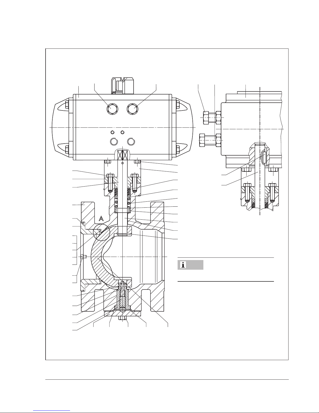
SAMSON PFEIFFER TypeAT Actuator
SAMSON Type3278 Actuator
Detail A (seal) is shown in Fig.3.
Note
Fig.1: Sectional drawing of Type3310 Valve
Page 8
8 EB 8222 EN
Mounting
Fail-close
When the pressure is relieved from the
rotary actuator or the supply air fails, the
actuator springs close the valve. The valve
opens opposing the force of the actuator
springs when the signal pressure increases.
Fail-open
When the pressure is relieved from the
rotary actuator or the supply air fails, the
actuator springs open the valve. The valve
closes opposing the force of the actuator
springs when the signal pressure increases.
2.1.2 TypeDAP (double-acting
version)
The TypeDAP Rotary Actuator (double-acting) has no springs. A dened nal position
is not reached when the supply air fails.
3 Mounting
3.1 Assembling valve and
actuator
3.1.1 Type3310-SRP
Proceed as follows if the valve and actuator
have not been assembled by SAMSON:
In the standard actuator version (SRP =
single-acting with spring return mechanism),
the spring return mechanism is designed to
close clockwise when there is no signal
pressure.
If you require a different direction of rotation
or a double-acting actuator (DAP = double-
acting without spring return mechanism), this
specication must be submitted on ordering
the actuator.
Table1: Type3310-SRP
Fail-safe
position
Springs Characteristic
Fail-close Clockwise Equal percentage
Fail-close Counterclockwise Linear
Fail-open Clockwise Linear
Fail-open Counterclockwise Equal percentage
The square drive allows the actuator to be
mounted on the segmented ball valve offset
at angles of 90° in such a way that it is either in the upright or horizontal position to
meet the installation requirements.
Note
Page 9

EB 8222 EN 9
Mounting
Fail-close
1. Place the segmented ball (8) of the valve
in the CLOSED position (0° angle of rotation).
2. Fasten the yoke (3) to the ange of the
valve shaft using two or four screws (depending on the valve size).
3. If necessary, place the shaft adapter on
the valve shaft. Slide the actuator over
the adapter or valve shaft (4) and fasten
it onto the yoke with four screws.
4. Adjust the stop bolt (12.1 or 12.2 depending on the direction of rotation) to
the point where the valve is completely
closed and align the markings on the
shaft and packing gland.
5. Lock the position of the stop bolt with the
lock nut.
6. Apply a signal pressure to the signal
pressure connection which corresponds
to the number of actuator springs (see
actuator nameplate).
7. Turn the other stop bolt until the segmented ball stops at an opening angle of 90°.
8. Lock the position of the stop bolt with the
lock nut.
Fail-open
1. Place the segmented ball (8) of the valve
in the OPEN position (90° angle of rotation).
2. Fasten the yoke (3) to the ange of the
valve shaft using two or four screws (depending on the valve size).
3. If necessary, place the shaft adapter on
the valve shaft. Slide the actuator over
the adapter or valve shaft (4) and fasten
it onto the yoke (3) with four screws
(3.1).
4. Adjust the stop bolt (12.1 or 12.2 depending on the direction of rotation) to
the point where the valve is completely
open at 90° and align the markings on
the shaft and packing gland.
5. Lock the position of the stop bolt with the
lock nut.
6. Apply a signal pressure to the signal
pressure connection which corresponds
to the number of actuator springs (see
actuator nameplate).
7. Turn the other stop bolt until the segmented ball is completely closed and align the
markings on the shaft and packing
gland.
8. Lock the position of the stop bolt with the
lock nut.
3.1.2 Type3310/3278
If the valve and actuator have not been assembled by SAMSON, mount the actuator
onto the body ange 1 or 2 depending on
the characteristic and fail-safe position.
'1' or '2' is cast on the corresponding side of
the body.
Table2: Type3310/3278
Fail-safe
position
Characteristic Body ange
Fail-close Equal percentage 2
Fail-close Linear 1
Fail-open Equal percentage 1
Fail-open Linear 2
Page 10

10 EB 8222 EN
Mounting
The four feather key notches on the actuator
shaft arranged every 90° allow the rotary
actuator to be mounted on the segmented
ball valve offset at angles of 90° in such a
way that it is either in the upright or horizontal position to meet the installation requirements.
Fail-close
1. Completely undo both stop bolts (13.1
and 13.2) on the rotary actuator. Turn
the stop bolt (13.2) clockwise until the
grooves of the actuator shaft are aligned
with the actuator axis horizontally or vertically.
2. Place the segmented ball (8) of the valve
in the CLOSED position (0° angle of rotation).
3. Fasten the yoke (3) to the ange of the
valve shaft using two or four screws (depending on the valve size).
4. Slide the actuator over the valve shaft (4)
and fasten it onto the yoke (3) with four
screws.
5. Undo the stop bolt (13.2) again.
6. Adjust the stop bolt (13.2) to the point
where the valve is completely closed and
align the markings on the shaft and
packing gland.
7. Apply a supply pressure required for the
spring range (see actuator nameplate) to
the loading pressure connection to open
the valve.
8. Turn the stop bolt (13.1) clockwise until
the segmented ball (8) of the valve is in
the OPEN position (90° angle of rotation).
9. Lock the position of both stop bolts with
the lock nuts.
Fail-open
1. Completely undo both stop bolts (13.1
and 13.2) on the rotary actuator. Turn
the stop bolt (13.1) clockwise until the
grooves of the actuator shaft are aligned
with the actuator axis horizontally or vertically.
2. Place the segmented ball (8) of the valve
in the OPEN position (90° angle of rotation).
3. Fasten the yoke (3) to the ange of the
valve shaft using two or four screws (depending on the valve size).
4. Slide the actuator over the valve shaft (4)
and fasten it onto the yoke (3) with four
screws.
5. Undo the stop bolt (13.1) again.
6. Apply a supply pressure required for the
spring range (see actuator nameplate) to
the loading pressure connection to close
the valve.
7. Adjust the stop bolt (13.1) to the point
where the segmented ball is completely
closed and align the markings on the
shaft and packing gland.
8. Disconnect the supply air from loading
pressure connection.
9. Turn the stop bolt (13.2) clockwise until
the segmented ball (8) of the valve is in
the OPEN position (90° angle of rotation).
10. Lock the position of both stop bolts with
the lock nuts.
Page 11

EB 8222 EN 11
Mounting
3.2 Mounting position
Prior to installing the valve into the pipeline,
place it in the CLOSED position to allow the
seat to be centered properly with the segmented ball.
The control valve can be installed into a
pipeline either in the upright or horizontal
position. However, the following points regarding the direction of ow must be observed:
− Install the valve into the pipeline in such
a way that the bottom half of the segmented ball opens in the direction of the
ow.
This helps to prevent dirt deposits from
accumulating and blocking the valve
when it opens. The direction of medium
ow into the ball also prevents the medium from collecting unnecessarily in the
shaft bearings.
− The standard direction of ow (onto the
segmented ball) is indicated by SAMSON
by an arrow on the valve body.
− If the direction of ow is be reversed,
e.g. required for abrasive media, indicate the reversed direction by using the
arrow plate and the two slotted pins included in the scope of delivery.
This direction of ow causes the pressure
of the process medium to constantly act
on the packing. On tightening the ange
bolts, make sure that an even pressure is
exerted on the gaskets.
3.3 Signal pressure connection
The signal pressure connection of the rotary
actuator is designed as a borehole with a
G
1
/
8
female thread for small actuators and
with G¼ female thread for large actuators.
The connection allows in compliance with
VDE/VDE3845 guidelines the connection of
a solenoid valve, e.g. Type3963, or a limit
switch with or without a solenoid valve
(Type3776/3777).
The corresponding accessories are available
to mount SAMSON positioners.
Note
Page 12

12 EB 8222 EN
Operation
4 Operation
4.1 Changing the fail-safe
action
The fail-safe action of Type3278 Actuator
can be changed from fail-close to fail-open
or vice versa after the valve has been installed. In this case, the side where the rotary
actuator is mounted must be changed (see
Table2).
The pistons of the TypeSRP Actuator must be
reversed to change the fail-safe action.
Refer to the mounting and operating instructions of the rotary actuator used for further
details, for example about changing the
spring range to achieve other actuator
torques.
5 Servicing
The control valve is subject to normal wear,
especially at the seat, segmented ball and
packing. Depending on the operating conditions, check the valve at regular intervals to
prevent possible failure before it can occur.
External leakage can indicate that the packing is defective.
If the valve does not close tightly, tight shutoff may be impaired by dirt stuck between
the seat ring and segmented ball or by damaged facings.
Î If you intend to remove parts to clean
them, rst mark the position of the seat
ring (11.8) in the body for a valve with
soft-seated ball. This will help you to replace the seat ring in its correct position
on reassembling the valve.
Î To replace the seat ring (11.6 or 11.8),
proceed as described in section5.3.
Î Before starting any work on the valve
body, rst remove the actuator (see section5.1).
Remove the valve from the pipeline before
removing any parts from the valve. Before
proceeding, depressurize the relevant plant
section.
Wait until the medium cools down if hot media are used.
5.1 Removing the actuator
from the valve
Î Unscrew the two or four screws on the
ange of the valve shaft and pull off the
actuator together with the yoke (3) from
the valve.
5.2 Replace the packing
The valves in NPS1 to 12 are tted with a
V-ring packing.
1. Undo the screws (2.2). Lift off the pack-
ing gland (2) with the bearing bushing
(2.1).
Note
WARNING
!
Page 13

EB 8222 EN 13
Servicing
2. Pull all the packing parts out of the packing chamber using a suitable tool. Clean
the packing chamber thoroughly.
3. Renew the packing (2.3). Slide the packing parts over the shaft (4) into the packing chamber.
4. Push the packing gland (2) together with
bearing bushing (2.1) onto the shaft (4).
Tighten the packing gland using the
screws (2.2).
5. Assemble as described in section5.4.
5.3 Replacing the seat ring
seal
1. Remove both anchoring screws (11.1)
with washers (11.2).
2. Take out the retainer (11) together with
the gasket (11.3).
If you are unable to remove the retainer,
use the special tool listed in Table3.
3. Soft-seated version: remove the support
ring (11.7) and seat ring (11.8).
Metal-seated version: remove in
sequence any washer(s) (11.4), metal
tubular seal (11.5) and seat ring (11.6).
4. Assemble as described in section5.4.
5.4 Assembly
Assemble in the reverse order. Special tools
are not necessary.
The retainer (11) can be pressed into the
body using, for example, a blank ange, by
tightening the ange bolts accordingly. In
this case, rst place the valve in the CLOSED
position to center the seat ring and segmented ball.
Tip
4
2.2
2
2.1
2.3
2.4
2.5
2.6
2.
7
2 Packing gland
2.1 Bearing bushing
2.2 Screws
2.3 V-ring packing
2.4 Washer
2.5 Spring
2.6 Washer
2.7 Spacer
4 Shaft
Fig.2: Packing
Page 14

14 EB 8222 EN
Servicing
Checking the friction torque
Check the friction torque (breakaway torque)
needed to open the valve according to Table4.
If the friction torque is different from the
torque specied in the table, proceed as follows:
Î Soft-seated version: turn the segmented
ball clockwise by 360° in the valve body
two or three times to let the seal adapt itself.
Î Metal-seated version: change the num-
ber of washers (11.4) used. If necessary,
omit the bottom washer on the valve
body side.
11
11.7
11.8
1
1
111811.1 11.2 11.3
11.5
11.6
11
11.4
Soft-seated version Metal-seated version
Seal
1 Body
8 Segmented ball
11 Retainer
11.1 Screw
11.2 Washer
Soft-seated version:
11.7 Support ring
11.8 Seat ring (PTFE)
Metal-seated version:
11.4 Washer
11.5 Metal tubular seal
11.6 Seat ring (metal)
Fig.3: Seat ring seal
Page 15

EB 8222 EN 15
Servicing
5.5 Replacing the segmented
ball, shafts and bearings
Risk of valve damage.
No clearance may exist between the
segmented ball and shafts. Therefore, the
shafts need to be replaced as well when the
segmented ball is replaced with a new one.
Furthermore, renew the bearing bushings
and seat rings as well as the ring and gasket
on the bottom ange as well.
5.5.1 Disassembly
1. Unscrew both bolts (10.3) and lift off
bottom ange (10) together with the ring
(10.2). Remove the ange gasket (10.1).
2. Unscrew the threaded pin (5.2) out of the
shaft and remove the clamping bolt
(5.3). Make sure that the locking pins
(5.4) do not get lost
3. Press out the support shaft.
If this is not possible, screw in a screw with a
washer (see Table3) in place of the threaded
pin. Turning the screw against the washer
loosens the support shaft.
4. Pull the bearing bushing (5.1) out of the
body.
5. Undo the screws (2.2) and lift off the
packing gland (2) with the bearing bushing (2.1).
6. Use snap ring pliers to pull the snap ring
(4.3) off the shaft and pull the shaft out
of the body using disassembling tool.
7. Pull all the packing parts out of the packing chamber using a suitable tool. Clean
the packing chamber thoroughly.
8. Remove the lower bearing bushing (4.1).
9. Take the segmented ball out of the body.
The segmented ball of valves in NPS1, 1 ½
and 2 must be removed from the retainer
side. Proceed as described in section5.3,
dismantling rst the retainer and then the
seat ring parts.
5.5.2 Assembly
We recommend ordering the assembly tools
listed in Table3 for reassembling the valve.
Assemble in the reverse order. Observe the
tightening torques specied in section7.
On inserting the shaft (4) into the body and
segmented ball, make sure that the shaft is
aligned correctly with the segmented ball
(the red marking on the shaft must be positioned at a right angle to the pipeline when
the valve is closed).
1. Insert the segmented ball (8) into the
valve body.
2. Push the bearing bushing (4.1) into the
body, then align the shaft (4) and use an
NOTICE
!
Tip
Note
Tip
Page 16

16 EB 8222 EN
Servicing
assembling tool to press the bearing
bushing into the segmented ball.
3. Use the part of the tool that is in the
bearing of the support shaft to slide the
segmented ball (8) onto the shaft (4) and
attach the snap ring (4.3).
4. Insert the locking pins (5.4) into the holes
of the support shaft (5), then position the
complete support shaft (5, 5.2, 5.3 and
5.4) on the bearing bushing (5.1) and
use the packing gland (2) to press them
in.
5. Align the segmented ball (8) centrally.
6. Screw the threaded pin (5.2) against the
clamping bolt (5.3) to obtain a
force-locking connection between the
support ange and segmented ball.
10
10.1
10.2
10.3
111811.1 11.2 11.3
44.3 4.15.35.25.15 5.4
1 Body
4 Shaft
4.1 Bearing bushing
4.3 Snap ring
5 Support shaft
5.1 Bearing bushing
5.2 Threaded pin
5.3 Clamping bolt
5.4 Locking pins
8 Segmented ball
10 Bottom ange
10.1 Flange gasket
10.2 Flange ring
10.3 Flange bolts
11 Retainer
11.1 Screw
11.2 Washer
11.3 Gasket
Fig.4: Sectional drawing
Page 17

EB 8222 EN 17
Changing the characteristic
7. Mount the packing with spacer (2.7),
washer (1.6), spring (2.5), thrust washer
(2.4), packing (2.3) and packing gland
(2).
Checking the friction torque
Check the friction torque (breakaway torque)
needed to open the valve according to Table4.
If the friction torque deviates from the
specied torque, proceed as described in
section5.4 on Checking the friction torque.
6 Changing the characteristic
Changing the characteristic from equal
percentage to linear and vice versa can be
performed by changing the actuator's
direction of rotation (see Table1 and
Table2).
Page 18

18 EB 8222 EN
Tools and tightening torques
7 Tools and tightening torques
7.1 Special tools
Table3: Special tools
Extracting tool for retainer (11)
Extracting tool
for support
shaft (5)
Tool to mount and remove the
shaft
Crossbeam Flange
Press tool for
support shaft
Press tool for
actuator shaft
NPS Order no.
1 1281-0011
1281-0007
1281-0026
1281-0019
1281-0023
1½ 1281-0012
2 1281-0013
1281-0008 1281-0020
3 1281-0014
4 1281-0015
1281-0009 1281-0027 1281-0021 1281-0024
6 1281-0016
8 1281-0017
1281-0010 1281-0028 1281-0022 1281-002510
1281-0018
12
Adapter for torque
wrench
Shaft with square drive Shaft with key drive
NPS
1, 1½, 2, 3 1281-0029 1281-0032
4, 6 1281-0030
1281-00338, 10
1281-0031
12
Page 19

EB 8222 EN 19
Tools and tightening torques
7.2 Tightening torques
Table4: Tightening and friction torques
Valve size NPS 1 1½ 2 3 4 6 8 10 12
Tightening torques in Nm
Screws (2.2) on packing gland
Bolts (10.3) on bottom ange
35 35 35 35 35 35 60 60 60
Friction torque to open the valve in Nm
Metal seal 8 10 11 19 40 70 100 155 155
Soft seal 9 12 14 24 50 100 170 260 260
7.2.1 Tightening torques for ange bolts
Table5: ANSI version
NPS Class
Flange bolts
(quality 8.8)
Min. tightening torque
inNm
1
150 4 x ½“ 35
300 4 x
5
/
8
” 45
1½
150 4 x ½” 45
300 4 x ¾” 65
2
150 4 x
5
/
8
” 90
300 8 x
5
/
8
” 45
3
150 4 x
5
/
8
” 125
300 8 x ¾” 65
4
150 8 x
5
/
8
” 80
300 8 x ¾” 80
6
150 8 x ¾” 125
300 12 x ¾” 80
8
150 8 x ¾” 165
300 12 x
7
/
8
” 125
10
150 12 x
7
/
8
” 155
300 16 x 1” 135
12
150 12 x
7
/
8
” 155
300 16 x
9
/
8
” 125
Page 20

20 EB 8222 EN
Tools and tightening torques
Table6: DIN version
DN PN
Flange bolts
(quality 8.8)
Min. tightening torque
inNm
25 10/40 4 x M12 40
40 10/40 4 x M16 55
50 10/40 4 x M16 75
80
10/16 8 x M16 55
25/40 8 x M16 55
100
10/16 8 x M16 70
25/40 8 x M20 85
150
10/16 8 x M20 125
25/40 8 x M24 150
200
10 8 x M20 165
16 12 x M20 110
25 12 x M24 135
40 12 x M27 150
250
10 12 x M20 140
16 12 x M24 165
25 12 x M27 185
40 12 x M30 205
300
10 12 x M20 140
16 12 x M24 165
25 16 x M27 140
40 16 x M30 165
Page 21

EB 8222 EN 21
Nameplate
8 Nameplate
The nameplate includes all details required to identify the valve.
DN3-
90˚
70˚
Kvs
Made in france
SAMSON
PN
3310 -
12 3
45
67
9
8
10
11
Fig.5: Nameplate
1 Type number
2 Serial number
3 Valve size DN.../NPS...
4 Plug seal:
ME Metal seal
PT PTFE
PK PEEK 450G Victrex
®
PK1 PEEK 450FC30 Victrex
®
5 Body material
6 Pressure rating PN…/Class…
7 Flow coefcient KVS…/CV…
Characteristic:
% Equal percentage
LIN Linear
8 PED text
9 Notied body
10 Year of manufacture
11 Direction of ow and maximum opening angle
Page 22

22 EB 8222 EN
Accessories
9 Accessories
Table7: Accessories
NPS
TypeSRP/DAP
Actuator (AT)
Connecting
ange
DIN3337
Mounting kit
order no.
Actuator area
in cm²
(Type3278)
Mounting kit
order no.
1
30
60
F05 1400-7316
160 (F07)
1400-7251
1½
60
100
F05
F07
1400-7316
1400-7317
2
60
100
150
F05
F07
F07
1400-7348
1400-7239
1400-7239
1400-7252
3
100
150
220
F07
F07
F10
1400-7239
1400-7239
1400-7732
4
220
300
450
F10
F10
F12
1400-7240
1400-7240
1400-7241
320 (F12) 1400-7255
6
300
450
600
F10
F12
F12
1400-7240
1400-7241
1400-7241
8
600
900
1200
F12
F14
F14
1400-7755
1400-7243
1400-7243
10
900
1200
F14
F14
1400-7243
12
900
1200
F14
F14
1400-7243
Page 23

EB 8222 EN 23
Technical data
10 Technical data
The technical data as well as the dimensions
and weights for the DIN and ANSI versions
of the Type3310 Segmented Ball Valve are
listed in the corresponding Data Sheet
uT8222.
11 Customer inquiries
Please submit the following details:
− Order number (specications on the
nameplate)
− Type, model number, nominal size and
valve version
− Pressure and temperature of the process
medium
− Flow rate in m³/h
− Signal pressure range (bench range)
− Installation drawing
Page 24

2019-02-14 · English
SAMSON AKTIENGESELLSCHAFT
Weismüllerstraße 3 · 60314 Frankfurt am Main, Germany
Phone: +49 69 4009-0 · Fax: +49 69 4009-1507
samson@samson.de · www.samson.de
EB 8222 EN
 Loading...