

Page 1
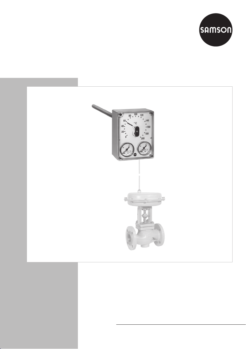
Pneumatic Controller for Temperature
Type 3301
Pneumatic Controller for Temperature
Type301-1
Mounting and
Operating Instructions
EB 7065 EN
Edition January 2014
Page 2

Denition of the signal words used in these mounting and operating instructions
Note:
Supplementary explanations, information and tips
2 EB 7065 EN
Page 3

Contents
Contents Page
1 General safety instructions .............................................................................4
2 Process medium and scope of application .......................................................5
2.1 Transportation and storage ............................................................................. 5
2.2 Versions ........................................................................................................5
3 Design and principle of operation ..................................................................6
3.1 Operating and indicating elements ..................................................................7
3.2 Pneumatic connections....................................................................................7
4 Installation ....................................................................................................8
4.1 Mounting position ..........................................................................................8
5 Operation ...................................................................................................10
5.1 Adjusting the operating direction ..................................................................10
5.2 Set point adjustment .....................................................................................10
5.3 Adjusting the proportional band ...................................................................10
5.4 Zero adjustment ...........................................................................................11
6 Maintenance ...............................................................................................11
7 Nameplate ..................................................................................................11
8 Technical data .............................................................................................12
9 Dimensions .................................................................................................12
10 Customer service .........................................................................................13
EB 7065 EN 3
Page 4

General safety instructions
1 General safety instructions
− The device must be mounted, started up or serviced by fully trained and
qualied personnel only; the accepted industry codes and practices are to
be observed. Make sure employees or third persons are not exposed to any
danger.
− According to these mounting and operating instructions, trained person-
nel refers to individuals who are able to judge the work they are assigned
to and recognize possible dangers due to their specialized training, their
knowledge and experience as well as their knowledge of the applicable
standards.
− To ensure appropriate use, only use the device in applications where the op-
erating pressure and temperatures do not exceed the specications used for
sizing the regulator at the ordering stage.
− The manufacturer does not assume any responsibility for damage caused by
external forces or any other external factors.
− Any hazards that could be caused in the controller by the process medium,
operating pressure or by moving parts are to be prevented by taking appropriate precautions.
− Proper transport, storage, installation, operation and maintenance are as-
sumed.
− SAMSON does not assume any liability for damage caused when the device
is not used as intended.
4 EB 7065 EN
Page 5
Process medium and scope of application
2 Process medium and scope of application
Pneumatic controller functioning as a proportional controller to control the temperature of gases
and vapors at the point of measurement with a pneumatic control valve.
Medium temperatures from 0 to 300 °C
The controller compares the temperature measured by the xed expansion bulb sensor with the
adjusted set point and issues a pneumatic signal between 0.2 to 1bar at the output. This signal
pressure acts on the connected pneumatic control valve. The controller requires a supply pres-
sure of 1.4bar. The measured temperature is indicated at the controller.
2.1 Transportation and storage
Transportation and storage in the permissible temperature range from –10 to +90°C. Protect
the controller against adverse inuences, such as dirt or moisture during storage.
2.2 Versions
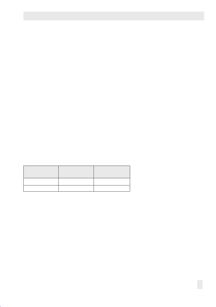
Two versions of the Type3301 Controller are available that have different set point ranges.
Table 1: Type3301∙ Versions
Type Set point range
3301-9001
3301-9002
0 to 200°C
100 to 300°C
Conguration ID
(Var.-ID)
Var.-ID 1063422
Var.-ID 1294879
The mounting parts are not included in the scope of delivery. They must be ordered separately
(see section 4 on page 8, Fig. 4 and Fig. 5).
EB 7065 EN 5
Page 6

Design and principle of operation
3 Design and principle of op-
eration
The controller mainly consists of the controller
housing containing a nozzle and apper system, pressure gauges for supply air and output pressure as well as the temperature sensor
with an outer tube (11) and Invar rod (12).
The different expansion properties of the Invar rod and tube materials produce a de-
ection each time the temperature at the sensor changes. This deection causes the differ-
ential plate (3) mounted on the plate spring
(9) to tilt on the ball (5), and causes the dis-
tance between the nozzle (2) and apper (4)
to change. The supply air pZ (1.4± 0.1bar)
ows through the restriction (1) to the nozzle
(2). These two components act as a pressure
divider controlled by the apper. As a result,
the output pressure pA (controlled variable 0.2
to 1bar) is regulated proportional to the system deviation and in relation to the xed operating point of 0.6bar.
The set point is adjusted at the screw (8) connected to the set point pointer (7). The proportional band is adjusted at the adjustment
screw (6). The position of the red dot on the
screw (6) indicates the operating direction adjusted.
Position in scale range^: The output pressure p
increases as the controlled variable
A
increases.
Position in scale range^: The output pres-
sure p
decreases as the controlled variable
A
increases.
1 Restriction
2 Nozzle
3 Differential plate
4 Flapper
5 Ball
6 Adjustment screw for Xp
(proportional band)
7 Set point pointer
8 Screw for set point adjustment
9 Plate spring
10 Base plate
11 Outer tube
12 Invar rod
Supply air (1.4± 0.1bar)
p
p
Z pA
Fig. 1: Functional diagram of Type3301
Z
Output pressure (0.2 to 1bar)
p
A
6 EB 7065 EN
Page 7

3.1 Operating and indicating elements
Set point pointer
Screw for set
point adjustment
Adjustment screw
for Xp and operating direction
Design and principle of operation
Pressure gauge for
supply air p
Z
Fig. 2: View from the front
Connection for
supply air p
Z
Connection for
output pressure p
A
output pressure p
A
3.2 Pneumatic connections
Pressure gauge for
The connections for supply air pZ and output pressure pA are located underneath the controller. They are designed as
Various screw ttings to connect pipes and plastic hoses are available.
Fig. 3: Pneumatic connections underneath the controller
1
/
8
NPT tapped holes.
Supply air
Output
EB 7065 EN 7
Page 8

Installation
4 Installation
The controller may be installed in any position. Make sure that the effective length of the
sensor (330mm) is completely surrounded by
the medium.
Install a reference thermometer close to the
controller to monitor the temperature (and to
check zero).
Screw gland (PN10)
Suitable for pipes and pressure vessels up to
max. 10bar. Seal the screw tting. Push in the
sensor with screw gland and coupling nut. Tighten the coupling nut.
*) G ½: Order no.: 1080-4881
G ¾: Order no.: 1080-4882
Screw gland with clamping nut (PN 40)
For use with pressure up to max. 40bar.
Tighten the clamping nut (instead of the coupling nut).
*) G ½: Order no.: 1080-4884
G ¾: Order no.: 1080-4885
4.1 Mounting position
To install the controller, a coupling sleeve with
G½ or G¾ female thread must be present at
the point of measurement. Screw or seal one
of the mounting parts shown in Fig.4 and 5
into this sleeve.
The mounting parts are not included in the
scope of delivery. They must be ordered separately. Select accessories required for the operating conditions at the site of installation.
Thermowell with thread (PN63) for pressures up to 63bar
A thermowell must be used in place of the screw
gland if the pressure at the sensor is greater than
the nominal pressure, if the medium to be controlled is corrosive or the controlled system is to
continue to operate while the controller is being
replaced. Screw the thermowell into the sleeve.
Push the temperature sensor into the thermowell
and fasten with the coupling nut.
*) G ½: Order no.: 1080-4888
G ¾: Order no.: 1080-4889
Fig. 4: Mounting parts for sensor · Screw glands and thermowell
8 EB 7065 EN
Page 9

Thermowell for welding (PN 63) for pressures up to 63 bar
Installation
Order no.: 1080-4890
Thermowell with ange DN 25 for PN 40 or PN 100
Order no.: 1080-4891 (PN40)
Order no.: 1080-4892 (PN100)
SW 32
Ø 22.3
373
SW 32
Ø 21.3
335 40
Clamping ange
For wall mounting, e.g. on pressureless vessels
in air-conditioning and ventilation plants.
32
8 Ø50
Screw the ange to the wall using the two
screws. Attach the temperature sensor in the
Ø12
ange using two other screws.
Order no.: 1090-9547 (PN40)
Order no.: 1080-4892 (PN100)
Ø26
Ø9.5
55
Fig. 5: Mounting parts for sensor · Thermowells and clamping ange
EB 7065 EN 9
75
Page 10

Operation
5 Operation
See Fig. 1 on page 6.
2.
Turn the adjustment screw (8) until the set
point pointer (7) points to the required
temperature on the scale.
5.1 Adjusting the operating
direction
Adjust the operating direction before start-up
as follows:
1.
Undo the screw on the cover and swivel
the guard plate out of the way.
Screw with guard plate
2.
Use a screwdriver to adjust the adjustment
screw (6) counterclockwise () or clockwise () to make the red dot on the screw
point to the required operating direction
on the scale.
Adjustment screw (6)
− Increasing/increasing^:
The output pressure p
temperature at the sensor increases.
− Increasing/decreasing ^:
The output pressure p
temperature at the sensor increases.
increases as the
A
decreases as the
A
Adjustment screw (8)
Note:
Do not turn the pointer past the adjustment range of the scale.
5.3 Adjusting the proportional
band
The continuously variable adjustment of the
gain is performed at the adjustment screw (6).
Gain
High
Low
Make sure that the adjustment is only performed within the operating direction determined in section 5.1, i.e. either on the left or
right side of the scale.
The gain can be adjusted continuously in the
direction of the arrow between 2 and 20%.
The red dot on the adjustment screw (6) serves
as the orientation mark.
5.2 Set point adjustment
1.
Undo the screw on the cover and swivel
the guard plate out of the way.
10 EB 7065 EN
Page 11

Maintenance
5.4 Zero adjustment
If the measured temperature (reading at the
reference thermometer) and the adjusted set
point of the controller deviate from each other, you need to readjust zero.
Unscrew the four corner screws on the
1.
cover and remove cover.
Use a screwdriver to hold the screw for
2.
set point adjustment (8) inplace and turn
the set point pointer (7) until the indicated
value matches the temperature measured
at the reference thermometer.
Set point pointer (7)
Screw for set point adjustment (8)
3. Adjust the set point again.
6 Maintenance
See Fig. 1 on page 6.
The controller only functions properly when
the supply air entering the device is always
clean. Therefore, check the air lter and trap
installed in the upstream air reducing station
regularly. If necessary, clean or renew the lter.
Insufciently cleaned supply air will cause the
restriction (1) to become blocked.
To clean the restriction, remove the nozzle
head (between the pneumatic connections underneath the housing, see photo).
Screw with Nozzle head
catch
1.
Undo screw for catch using a suitable
screwdriver.
Move the catch to release the nozzle
2.
head.
3. Pull out the nozzle head. Use compressed
air to blow a blocked nozzle. Insert a ne
wire (max. Ø 0.25 mm) to remove any
stubborn dirt particles.
→
→
7 Nameplate
SAMSON 3301-
Pneumatischer P-Regler für Temperatur
Pneumatic P-Controller for Temperature
Régulateur pneumatique P de Température
2
1
3
Made in France
Fig. 6: Nameplate
EB 7065 EN 11
Page 12

Technical data
8 Technical data
All pressures in bar (gauge)· Materials according to DINEN
Type 3301 Pneumatic Controller for Temperature
Measuring system
Bulb sensor Ø12mm, 400mm long, minimum immersion depth 330mm,
Material Stainless steel 1.4571
Set point, continuously adjustable 0 to 200 °C or 100 to 300 °C
Output
Control signal y 0.2 to 1 bar
Supply air Supply air 1.4± 0.1bar
Air consumption in steady state
Max. air output capacity
Proportional band X
Operating point 0.6bar
Temperature inuence 0.03 %/K
Ambient temperature range –10 to +90 °C
Max. operating pressure at the sensor 60 bar
Weight Approx. 2 kg
p
Mechanical-type expansion sensor
3
/h
0.25 m
n
3
/h
0.11 m
n
Continuously adjustable between 2 and 20 %
9 Dimensions
Ø12
130
Immersion
depth
330
100
400
54
Fig. 7: Dimensions in mm
12 EB 7065 EN
10
Page 13

10 Customer service
If malfunctions or defects occur, contact the
SAMSON After-sales Service Department
for support. Please send your inquiries to:
service@samson.de
The addresses of SAMSON AG, its subsidiaries, representatives and service facilities
worldwide can be found on the SAMSON
website, in all SAMSON product catalogs or
on the back of these Mounting and Operating Instructions.
To assist diagnosis and in case of an unclear
mounting situation, specify the following details:
(see section 7 on page 11):
− Model number
− Serial no.
− Temperature and process medium
− Installation drawing showing the exact
location of the controller and all the additionally installed components (shut-off
valves, thermometer, control valve etc.)
− For return inquiries: Phone number or e-
mail address
Customer service
EB 7065 EN 13
Page 14

Page 15

Page 16

SAMSON AG · MESS- UND REGELTECHNIK
Weismüllerstraße 3 · 60314 Frankfurt am Main · Germany
Phone: +49 69 4009-0 · Fax: +49 69 4009-1507
Internet: http://www.samson.de
EB 7065 EN
2014-01-27
 Loading...