

Page 1
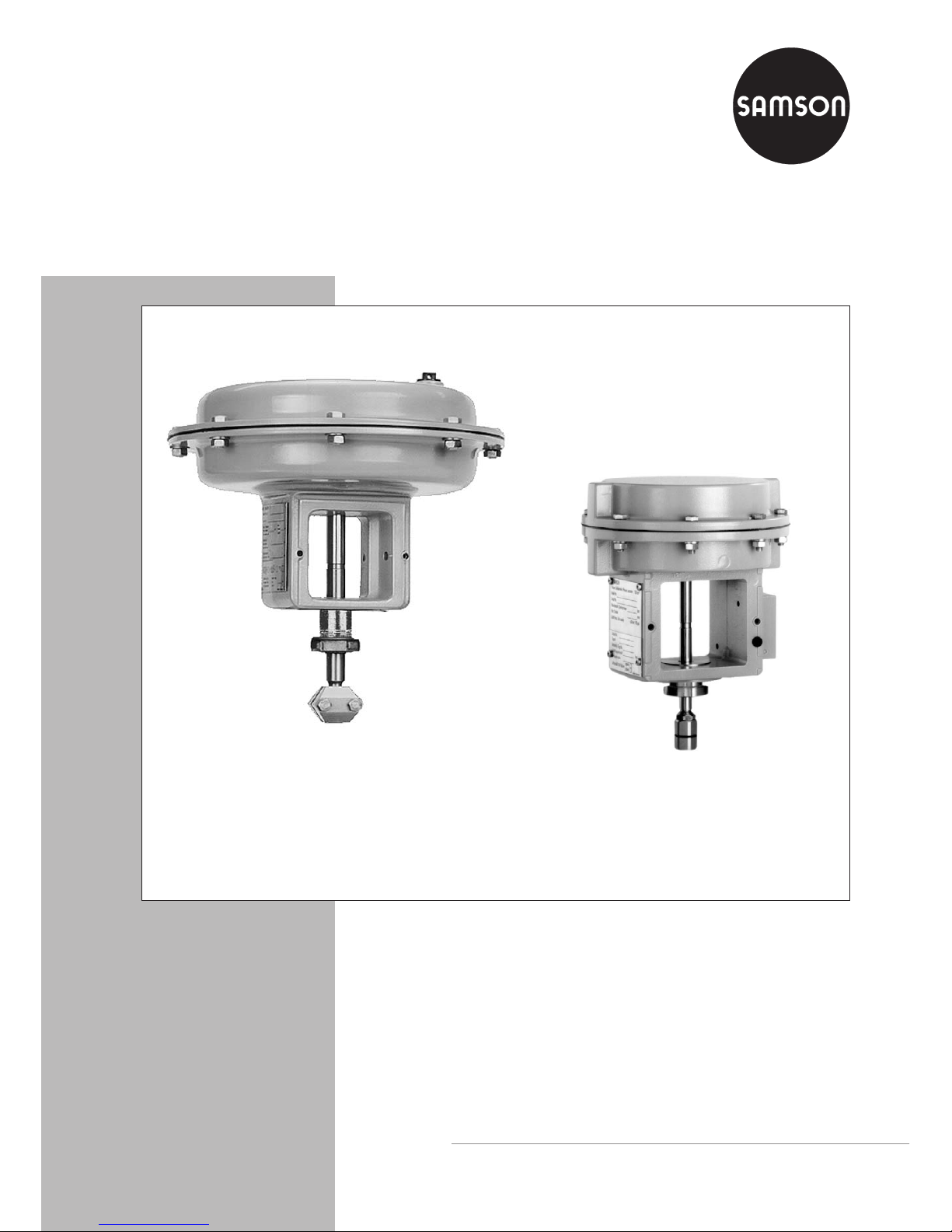
Pneumatic Actuator
Type 3277
Mounting and
Operating Instructions
EB 8311 EN
Edition July 2006
Fig. 1 · Type 3277 Pneumatic Actuator
Fig. 2 · Type 3277-5 Pneumatic Actuator
Page 2

1 Design and principle of
operation
The Type 3277 Pneumatic Actuators with an
effective diaphragm area of 240, 350 or
700 cm² are primarily mounted to control
valves from the Series 240, 250 and 280.
Type 3277-5 with a die-cast aluminum case
and an effective diaphragm area of
120 cm², is mounted to Type 3510 and Se
-
ries 240 Valves.
The actuator is made up of two diaphragm
cases, a rolling diaphragm and springs. The
lower diaphragm case is permanently fixed
to the yoke which allows the direct attachment of either a pneumatic or electropneumatic positioner or a limit switch.
Actuators with manual override (Fig. 5) additionally have a handwheel mounted on the
diaphragm case. The handwheel moves the
actuator stem over a spindle after the lock
-
ing mechanism (lock nut) has been disen
gaged. In addition, the actuator can be
equipped in a special version with a me
-
chanically adjustable travel stop.
The signal pressure creates a force at the di
aphragm surface which is balanced by the
springs (6) arranged in the actuator. The
number of springs and their compression
determine the bench range (signal pressure
range) while taking the rated travel into ac
count which is directly proportional to the
signal pressure. A maximum of 30 springs
can be installed, partly fitted inside one an
other.
The stem connector (16) connects the actuator stem (2) with the plug stem of the control
valve.
2 EB 8311 EN
Design and principle of operation
4
Assembly, start-up and operation of the device may only be performed by
trained and experienced personnel familiar with this product.
According to these mounting and operating instructions, trained personnel is
referred to individuals who are able to judge the work they are assigned to
and recognize possible hazards due to their specialized training, their
knowledge and experience as well as their knowledge of the relevant
standards.
4
Any hazards which could be caused by the signal pressure and moving
parts of the actuator are to be prevented by means of appropriate
measures.
4
Proper shipping and appropriate storage are assumed.
Page 3
Fail-safe action
When the signal pressure fails, the fail-safe
action of the actuator depends on whether
the springs are installed in the top or bottom
diaphragm chamber.
Actuator stem extends
When the signal pressure is reduced or the
air supply fails, the springs move the actua
tor stem downwards and close the valve.
The valve opens when the signal pressure is
increased enough to overcome the force ex
-
erted by the springs.
Actuator stem retracts
When the signal pressure is reduced or the
air supply fails, the springs move the actua
tor stem upwards and open the valve. The
valve closes when the signal pressure is in
-
creased enough to overcome the force ex
-
erted by the springs.
EB 8311 EN 3
Design and principle of operation
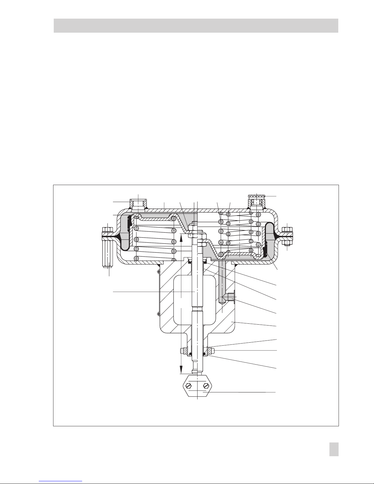
Fig. 3 · Sectional diagram of Type 3277 with 240, 350 and 700 cm² effective diaphragm area
5
1.1
1
6
6.1
3
8
12
12.1
11
10
12.1
13
2
15
16
4
7
a
9
1 Nut
1.1 Nut
2 Actuator stem
3 Vent plug
4 Loading pressure
connection
5 Top diaphragm
case
6 Springs
7 Diaphragm plate
8 Diaphragm
9 Nuts and bolts
10 Yoke with bottom
diaphragm case
11 Loading pressure
connection
12 Stem seal
12.1Dry bearing
13 Wiper
15 Ring nut
16 Stem connector
Dimension a
350 cm² = 209 mm
700 cm² = 246 mm
Page 4

Loading pressure connection
Type 3277 Actuator (Fig. 3)
In the Type 3277 Actuator with fail-safe ac
tion "Actuator stem extends", the loading
pressure is connected to the loading pres
sure connection (11) at the side of the yoke
to fill the bottom diaphragm chamber which
causes the actuator stem (2) to move up
-
wards. In an actuator with the fail-safe ac
tion "Actuator stem retracts", the loading
pressure is connected the loading pressure
connection (4) to fill the top diaphragm
chamber which causes the actuator stem to
move downwards.
Type 3277-5 Actuator (Fig. 4)
In the Type 3277-5 Actuator, the loading
pressure is connected to a borehole either at
the left or right of the yoke. A switchover
plate (14, accessories) directs the air to one
of the diaphragm chambers, depending on
the fail-safe action of the actuator ("Actuator
stem extends" or "Actuator stem retracts"),
which is determined by how the plate is
aligned with the mark (14.4).
4
Turn the switchover plate to align the
symbol (14.3) for the appropriate
fail-safe action with the mark (14.4). See
Fig. 4, bottom left. The operating direc
-
tion (>>) or (<>) of the positioner deter
-
mines whether the left or right attach
-
ment is to be used.
A connecting plate (accessories) is required
instead of the switchover plate if the actua
-
tor is operated without a positioner. The
loading pressure is directly connected to the
loading pressure connection (14.8) of the
connecting plate to fill the diaphragm cham
-
ber.
4
Turn the connecting plate to align the
symbol (14.3) for the appropriate
fail-safe action "Actuator stem extends"
or "Actuator stem retracts" with the mark
(14.4). See Fig. 4, bottom right.
4
Make sure that the flat gasket of the con
-
necting plate is correctly inserted.
4
The connecting plate has both NPT and
G threaded bores. Seal the bore not re
quired with a rubber gasket and square
plug.
Accessories: The switchover plate or con
necting plate must be ordered separately.
Please note that actuators with modification
index 01 e.g. 3277-531xxx20.01 (old =
.00) are equipped with new plates.
Old and new plates are not interchangeable.
In-
dex
Order no.
Switch-
over plate
New
Old
01001400-6822
1400-6819
Con-
necting
plate
New
Old: G thread
Old NPT thread
01
00
00
1400-6823
1400-6820
1400-6821
Note! The pneumatic actuators are designed
for a maximum supply pressure of 6 bar.
To prevent the actuator from being dam
aged, do not let the supply pressure exceed
the upper spring range value by more than
3 bar when the actuator is used for
flow-switching service (on-off valve) with the
fail-safe position "Actuator stem retracts".
Label actuators that have a reduced supply
pressure with a sticker "max. supply pres
-
sure limited to … bar".
Note! Refer to the operating instructions of
the corresponding valve on how to mount
and remove the actuator from the valve.
4 EB 8311 EN
Design and principle of operation
Page 5

EB 8311 EN 5
Design and principle of operation
Fig. 4 · Type 3277-5 Actuators with 120 cm2effective diaphragm area
Connecting plate
Actuator stem extends
Left attachment Right attachment
1 Nut
1.1 Nut
2.1 Bushing
5 Diaphragm case
6 Springs
7 Diaphragm plate
7.1 Metal plate
8 Diaphragm
9 Nuts and bolts
10 Yoke
12 Stem seal
12.1 Dry bearing
13 Wiper
14 Switchover or connecting
plate
Air routing:
14.1 for actuator stem extends
14.2 for actuator stem retracts
15 Ring nut
16 Stem connector
Actuator stem retracts
Left attachment Right attachment
Actuator stem
extends retracts
Switchover plate
14.3 Symbol
14.4 Marking for signal
pressure input
14.5 For left attachment
14.6 For right attachment
14.7 Seal with filter
14.8 Loading pressure
connection
Actuator with threaded
connection for a
micro-flow valve
Dimension a = 188.5 with 15 mm travel
and 185.5 with 20 mm travel
Page 6

2 Operation
Note!
It is important for a trouble-free operation of
the Type 3277 Actuator that the vent plug
(3) is not blocked.
Make sure in versions with a handwheel that
the plug stem can move freely when the
valve is being positioned by the pneumatic
actuator by moving the handwheel into a
neutral position.
2.1 Reversing the operating
direction (fail-safe action)
The operating direction, i.e. fail-safe action,
of pneumatic actuators can be changed.
Prior to proceeding, you must remove the
actuator from the valve.
The fail-safe action is represented by a symbol on the nameplate.
"Actuator stem extends"
"Actuator stem retracts"
Caution!
To disassemble an actuator with pre
-
loaded actuator springs (recogniza
-
ble by the long bolts on the di
aphragm chambers), always undo
the short bolts first and then unthre
ad the long bolts slowly and evenly
until the actuator springs are fully
decompressed.
2.1.1 Standard actuator
Reversing the fail-safe action "Actuator
stem extends" to "Actuator stem retracts"
Note!
Actuators with 700 cm² (travel = 30 mm)
that are mounted to valves with 15 mm
travel, are preloaded by approx. 75 % on
mounting them to the valve.
The signal pressure range is recorded on the
nameplate when the actuators have been
preloaded on mounting them to the valve.
1. Unthread nuts and remove the bolts (9)
from the diaphragm cases.
2. Lift off the top diaphragm case (5) and
remove the springs (6).
3. Pull the actuator stem (2) with diaphragm plate (7) and diaphragm (8) out
of the yoke (10).
4. Unscrew nut (1), while holding the nut
(1.1) stationary or clamping the actuator
stem with a suitable tool.
Caution! Proceed carefully to avoid
damaging the seals of the actuator stem.
6 EB 8311 EN
Operation
Page 7

Caution!
Do not loosen the nut (1.1) on the actuator
stem. It is painted over to protect it.
If, however, it has been loosened, it is essen
-
tial that the dimension a (Figs. 3 and 4)
measured from the top of the nut to the bot
-
tom of the actuator stem is kept.
5. Apply lubricant/sealant (order no.
8152-0043) to the sealing places on the
actuator stem.
6. Turn over top diaphragm case (5). Place
the actuator stem with diaphragm plate,
diaphragm and metal plate (7.1), if applicable in the case.
7. Insert the springs (6) and slide the yoke
with bottom diaphragm case over the
actuator stem.
8. Screw tight the nuts and bolts of the diaphragm cases. Remove vent plug (3) in
Type 3277 Actuator.
Proceed in the same manner for the
Type 3277-5 Actuator intended for the mi
-
cro-valve, but additionally attach the bush
-
ing (2.1) for the mechanical travel stop.
The springs now press from below against
the diaphragm plate and cause the actuator
stem to retract (fail-safe action). The actuator
stem only starts to extend when the signal
pressure overcomes the force of the springs.
9. Record the changed fail-safe action on
the nameplate!
Reversing the fail-safe action "Actuator
stem retracts" to "Actuator stem extends"
1. Unthread nuts and remove the bolts (9)
and lift off the top diaphragm case (5).
2. Pull the actuator stem with diaphragm
plate, diaphragm and metal plate (7.1),
if applicablethe diaphragm plate (7) out
of the yoke and bottom diaphragm case
(10).
3. Unscrew nut (1), while holding the nut
(1.1) stationary or clamping the actuator
stem with a suitable tool.
Caution! Proceed carefully to avoid
damaging the seals of the actuator stem.
4. Remove the diaphragm plate with diaphragm and replace them in reverse order. Screw tight nut (1).
5. Coat the sealing parts of the actuator
stem with sealant/lubricant (order no.
8152-0043).
6. Insert the actuator stem with diaphragm
plate, diaphragm and metal plate (7.1),
if applicable, into the bottom diaphragm
case with yoke.
7. Insert springs (6) and place the top dia
phragm case back on. Screw tight the
nuts and bolts of the diaphragm cases.
8. Screw the vent plug (3) into the top load
ing pressure connection of the
Type 3277 Actuator.
Proceed in the same manner for the
Type 3277-5 Actuator intended for the mi
-
cro-valve, but additionally attach the bush
-
ing (2.1) for mechanical travel stop.
The springs now press from the top against
the diaphragm plate and cause the actuator
stem to extend (fail-safe action). The actua
-
EB 8311 EN 7
Reversing the operating direction (fail-safe action)
Page 8

tor stem only starts to retract when the signal
pressure overcomes the force of the springs.
9. Record the changed fail-safe action on
the nameplate!
2.1.2 Actuator with handwheel
Type 3277 (Fig. 5) only
1. Undo lock nut (20) and relieve the
springs (6) by turning the handwheel
(17).
2. Loosen threaded pin (26) and unscrew
coupling nut (25) from the coupling
(22).
3. Knock out the clamping sleeve (23) and
remove the ring (24).
4. Unthread the ring nut (15) and lift off the
flange part (21) together with the coupling nut (25).
Reversing the fail-safe action "Actuator
stem extends" to "Actuator stem retracts"
4
Proceed as described in section 2.1.1.
However, use the word "spindle with nut
(27)" in place of "nut (1)".
After reversing the operating direction:
1. Replace the flange part (21) with ring
nut (15) and coupling nut (25).
2. Tighten ring nut (15). Attach the ring
(24) with clamping sleeve (23).
3. Screw coupling nut (25) as far as it will
go onto the coupling (22) and secure
with threaded pins (26).
Reversing the fail-safe action "Actuator
stem retracts" to "Actuator stem extends"
4
Proceed as described in section 2.1.1.
However, use the word "spindle with nut
(27)" in place of "nut (1)".
After reversing the operating direction:
1. Replace the flange part (21) with ring
nut (15) and coupling nut (25).
2. Tighten ring nut (15). Attach the ring
(24) with clamping sleeve (23). Attach
the ring (24) with clamping sleeve (23).
3. Screw coupling nut (25) as far as it will
go onto the coupling (22) and secure
with threaded pins (26).
8 EB 8311 EN
Reversing the operating direction (fail-safe action)
Page 9

EB 8311 EN 9
Reversing the operating direction (fail-safe action)
17
20
21
22
24
15
13
3
4
6
9
6.1
7
11
12.1
13
23
26
25
12
5
27
8
10
12
Fig. 5 · Type 3277 Actuator with additional handwheel
2 Actuator stem
3 Vent plug
4 Loading press. connection
5 Top diaphragm case
6 Springs
6.1 Additional springs
7 Diaphragm plate
8 Diaphragm
9 Nuts and bolts
10 Bottom diaphragm case
11 Loading press. connection
15 Ring nut
12 Stem seal
12.1 Dry bearing
13 Wiper
17 Handwheel
20 Lock nut
21 Flange part
22 Coupling
23 Clamping sleeve
24 Ring
25 Coupling nut
26 Threaded pin
27 Spindle with nut
Neutral position
Pointer points to groove
in coupling (22)
Page 10
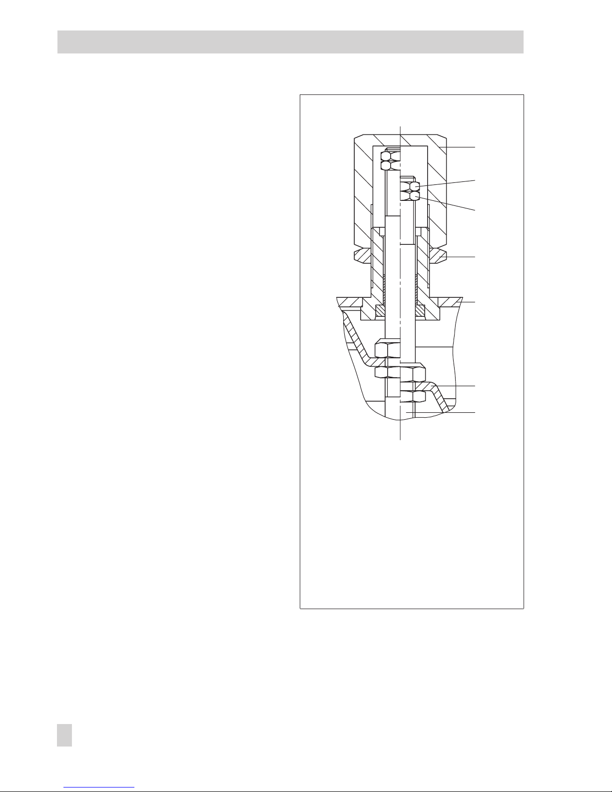
2.2 Adjusting the travel stop
(with Type 3277 in special version only)
The travel stop can be adjusted upwards or
downwards to 50% of the travel.
Downward travel stop
(actuator stem extends)
1. Undo the lock nut (34) and unscrew the
cap (33).
2. Undo the lock nut (31) and adjust the
nut (32) to set required travel stop.
3. Tighten the lock nut (31) again.
Upward travel stop
(actuator stem retracts)
1. Undo the lock nut (34) and adjust the
cap (33) to set the required travel stop.
2. Tighten the lock nut (34) again.
10 EB 8311 EN
Adjusting the travel stop
Fig. 6 · Travel stop
33
31
32
34
5
7
2
2 Actuator stem
5 Top diaphragm case
7 Diaphragm plate
31 Lock nut
32 Nut
33 Cap
34 Lock nut
Actuator stem
extends
Actuator stem
retracts
Page 11

3 Replacing the diaphragm and
stem seal
3.1 Diaphragm
(Fig. 3)
1. Remove the diaphragm plate (7) to
gether with diaphragm (8) and actuator
stem (2) from the diaphragm case as de
-
scribed in section 2.1.1.
2. Remove the hose clamp and pull it to
-
gether with the diaphragm (8) off the di
aphragm plate (7) (not necessary with
Type 3277-5 as the diaphragm is held
in place by the metal plate (7.1)).
3. Stretch the new diaphragm onto the diaphragm plate. Fit the hose clamp evenly
into the groove intended for it and
tighten.
4. Reassemble actuator as described in
section 2.1.1.
3.2 Stem seal
1. Remove the diaphragm plate (7) to
gether with the actuator stem (2) from
the diaphragm case as described in
section 2.1.1.
2. Coat the new stem seal (12) with lubri
cant/sealant (order no. 8152-0043)
and insert it.
3. If necessary, replace the dry bearing
(12.1) and wiper (13) with new ones as
well.
4. Reassemble the actuator as described in
section 2.1.1.
4 Customer inquiries
Please specify the following details on mak
-
ing inquires:
4
Type and model number
4
Effective diaphragm area
4
Bench range (spring range) in bar
4
Actuator version and its operating direc
-
tion
Dimensions and weights
Refer to the Data Sheet T 8310-1 EN dimen
sions and weights of the different actuator
versions.
EB 8311 EN 11
Replacing the diaphragm and stem seal
Fig. 7 · Actuator stem seal
12
12.1
2
13
Page 12

SAMSON AG · MESS- UND REGELTECHNIK
Weismüllerstraße 3 · 60314 Frankfurt am Main · Germany
Phone: +49 69 4009-0 · Fax: +49 69 4009-1507
Internet: http://www.samson.de
EB 8311 EN
S/Z 2006-08
 Loading...