

Page 1
Type 3251 Valve
In combination with an actuator,
e.g. a SAMSON Type3271 or Type3277 Pneumatic Actuator
ANSI version
Translation of original instructions
Type3251 Valve with Type3271 Actuator
Mounting and
Operating Instructions
EB 8052 EN
Edition July 2016
Page 2
Note on these mounting and operating instructions
These mounting and operating instructions assist you in mounting and operating the device
safely. The instructions are binding for handling SAMSON devices.
Î For the safe and proper use of these instructions, read them carefully and keep them for
later reference.
Î If you have any questions about these instructions, contact SAMSON‘s After-sales Service
Department (aftersalesservice@samson.de).
The mounting and operating instructions for the devices are included in
the scope of delivery. The latest documentation is available on our website
(www.samson.de) > Product documentation. You can enter the document
number or type number in the [Find:] eld to look for a document.
Denition of signal words
!
DANGER
Hazardous situations which, if not avoided,
will result in death or serious injury
!
WARNING
Hazardous situations which, if not avoided,
could result in death or serious injury
2 EB 8052 EN
!
NOTICE
Property damage message or malfunction
Note
Additional information
Tip
Recommended action
Page 3

Contents
1 Safety instructions and measures ...................................................................5
1.1 Notes on possible severe personal injury .........................................................8
1.2 Notes on possible personal injury ...................................................................8
1.3 Notes on possible property damage ................................................................9
2 Markings on the control valve ......................................................................12
2.1 Valve nameplate ..........................................................................................12
2.2 Actuator nameplate ......................................................................................13
2.3 Material number ..........................................................................................13
3 Design and principle of operation ................................................................14
3.1 Fail-safe positions ........................................................................................14
3.2 Versions ......................................................................................................16
3.3 Technical data .............................................................................................16
4 Measures for preparation ............................................................................24
4.1 Unpacking ..................................................................................................24
4.2 Transporting and lifting ................................................................................24
4.2.1 Transporting ................................................................................................25
4.2.2 Lifting ..........................................................................................................25
4.3 Storage .......................................................................................................28
4.4 Preparation for installation ............................................................................29
5 Mounting and start-up .................................................................................30
5.1 Mounting the actuator onto the valve .............................................................30
5.2 Installing the valve into the pipeline ...............................................................31
5.2.1 Checking the installation conditions ...............................................................31
5.2.2 Additional ttings .........................................................................................32
5.2.3 Installing the control valve .............................................................................33
5.3 Quick check ................................................................................................34
6 Operation ...................................................................................................36
6.1 Working in manual mode .............................................................................36
7 Servicing.....................................................................................................38
7.1 Replacing the gasket ....................................................................................39
7.1.1 Standard version..........................................................................................39
7.1.2 Version with insulating section or bellows seal ................................................41
EB 8052 EN 3
Page 4

Contents
7.2 Replacing the packing ..................................................................................41
7.2.1 Standard version..........................................................................................41
7.2.2 Version with insulating section .......................................................................43
7.3 Replacing the seat and plug ..........................................................................45
7.3.1 Standard version..........................................................................................47
7.3.2 Version with insulating section .......................................................................48
7.4 Preparation for return shipment .....................................................................49
7.5 Ordering spare parts and operating supplies .................................................49
8 Malfunctions ...............................................................................................50
8.1 Troubleshooting ...........................................................................................50
8.2 Emergency action ........................................................................................51
9 Decommissioning and disassembly ..............................................................52
9.1 Decommissioning .........................................................................................52
9.2 Removing the valve from the pipeline .............................................................52
9.3 Removing the actuator from the valve ............................................................53
9.4 Disposal ......................................................................................................53
10 Annex.........................................................................................................54
10.1 After-sales service ........................................................................................54
10.2 Certicates ..................................................................................................54
10.3 Spare parts .................................................................................................56
4 EB 8052 EN
Page 5

Safety instructions and measures
1 Safety instructions and measures
Intended use
The SAMSON Type3251 Globe Valve in combination with an actuator (e.g. Type3271 or
Type3277 Pneumatic Actuator) is designed to regulate the ow rate, pressure or temperature
of liquids, gases or vapors. The valve with its actuator is designed to operate under exactly
dened conditions (e.g. operating pressure, process medium, temperature). Therefore, operators must ensure that the control valve is only used in applications that meet the specications
used for sizing the valve at the ordering stage. In case operators intend to use the control
valve in other applications or conditions than specied, contact SAMSON.
SAMSON does not assume any liability for damage resulting from the failure to use the
valve for its intended purpose or for damage caused by external forces or any other external
factors.
Î Refer to the technical data and nameplate for limits and elds of application as well as
possible uses.
Reasonably foreseeable misuse
The control valve is not suitable for the following applications:
− Use outside the limits dened during sizing and in the technical data
− Use outside the limits dened by the valve accessories mounted on the control valve
Furthermore, the following activities do not comply with the intended use:
− Use of non-original spare parts
− Performing service and repair work not described in these instructions
Qualications of operating personnel
The control valve must be mounted, started up, serviced, and repaired by fully trained and
qualied personnel only; the accepted industry codes and practices are to be observed.
According to these mounting and operating instructions, trained personnel refers to
individuals who are able to judge the work they are assigned to and recognize possible
hazards due to their specialized training, their knowledge and experience as well as their
knowledge of the applicable standards.
EB 8052 EN 5
Page 6

Safety instructions and measures
Personal protective equipment
We recommend wearing the following protective equipment depending on the process medium:
− Protective clothing, gloves, and eyewear in applications with hot, cold, and/or corrosive
media
− Wear hearing protection when working near the valve.
Î Check with the plant operator for details on further protective equipment.
Revisions and other modications
Revisions, conversions or other modications to the product are not authorized by SAMSON.
They are performed at the user's own risk and may lead to safety hazards, for example.
Furthermore, the product may no longer meet the requirements for its intended use.
Safety devices
Upon supply air or control signal failure, the valve moves to its fail-safe position (see
section3.1). The fail-safe action of the actuator is the same as its direction of action and is
specied on the nameplate of SAMSON actuators (see actuator documentation).
Warning against residual hazards
To avoid personal injury or property damage, plant operators and operating personnel must
prevent hazards that could be caused in the control valve by the process medium, the operating pressure, the signal pressure or by moving parts by taking appropriate precautions. They
must observe all hazard statements, warning and caution notes in these mounting and operating instructions, especially for installation, start-up, and service work.
Responsibilities of the operator
The operator is responsible for proper operation and compliance with the safety regulations.
Operators are obliged to provide these mounting and operating instructions as well as the
referenced documents to the operating personnel and to instruct them in proper operation.
Furthermore, the operator must ensure that operating personnel or third persons are not exposed to any danger.
Responsibilities of operating personnel
Operating personnel must read and understand these mounting and operating instructions as
well as the referenced documents and observe the hazard statements, warning and caution
notes specied in them. Furthermore, the operating personnel must be familiar with the applicable health, safety and accident prevention regulations and comply with them.
6 EB 8052 EN
Page 7

Safety instructions and measures
Referenced standards and regulations
The control valves comply with the requirements of the European Pressure Equipment Directive 2014/68/EU. Valves with a CE marking have a declaration of conformity, which includes information about the applied conformity assessment procedure. This declaration of
conformity is included in the Appendix of these instructions (see section10.2).
According to the ignition risk assessment performed in accordance with EN13463-1:2009,
section 5.2, the non-electrical control valves do not have their own potential ignition source
even in the rare incident of an operating fault. As a result, they do not fall within the scope of
Directive 2014/34/EU.
Î For connection to the equipotential bonding system, observe the requirements specied in
section 6.4 of EN60079-14 (VDE0165 Part 1).
Referenced documentation
The following documents apply in addition to these mounting and operating instructions:
− Mounting and operating instructions for mounted actuator, e.g. uEB8310-X for
SAMSON Type3271 and Type3277 Actuators
− Mounting and operating instructions for mounted valve accessories (positioner, solenoid
valve etc.)
− uWA0029 for tools and tightening torques
EB 8052 EN 7
Page 8

Safety instructions and measures
1.1 Notes on possible severe personal injury
!
DANGER
Risk of bursting in pressure equipment.
Control valves and pipelines are pressure equipment. Improper opening can lead to
valve components bursting.
Î Before starting any work on the control valve, depressurize all plant sections
concerned as well as the valve.
Î Drain the process medium from all the plant sections concerned as well as the
valve.
Î Wear personal protective equipment.
1.2 Notes on possible personal injury
!
WARNING
Crush hazard arising from moving parts.
The control valve contains moving parts (actuator and plug stems), which can injure
hands or ngers if inserted into the valve.
Î Do not insert hands or ngers into the yoke while the valve is in operation.
Î While working on the control valve, disconnect and lock the pneumatic air supply as
well as the control signal.
Risk of personal injury when the actuator vents.
While the valve is operating, the actuator may vent during closed-loop control or when
the valve opens or closes.
Î Install the control valve in such a way that the actuator does not vent at eye level.
Î Use suitable silencers and vent plugs.
Î Wear eye protection when working in close proximity to the control valve.
8 EB 8052 EN
Page 9

Safety instructions and measures
!
WARNING
Risk of personal injury due to preloaded springs.
Valves in combination with pneumatic actuators with preloaded springs are under tension. These control valves with SAMSON pneumatic actuators can be identied by the
long bolts protruding from the bottom of the actuator.
Î Before starting any work on the actuator, relieve the compression from the preload-
ed springs (see associated actuator documentation).
Risk of personal injury due to residual process medium in the valve.
While working on the valve, residual process medium can escape and, depending on
its properties, may lead to personal injury, e.g. (chemical) burns.
Î If possible, drain the process medium from all the plant sections concerned and the
valve.
Î Wear protective clothing, safety gloves, and eyewear.
Risk of burn injuries due to hot or cold components and pipelines.
Depending on the process medium, valve components, and pipelines may get very hot
or cold and cause burn injuries.
Î Allow components and pipelines to cool down or heat up.
Î Wear protective clothing and safety gloves.
1.3 Notes on possible property damage
!
NOTICE
Risk of valve damage due to contamination (e.g. solid particles) in the pipeline.
The plant operator is responsible for cleaning the pipelines in the plant.
Î Flush the pipelines before start-up.
Î Observe the maximum permissible pressure for valve and plant.
Risk of valve damage due to unsuitable medium properties.
The valve is designed for a process medium with dened properties.
Î Only use the process medium specied for sizing the valve.
EB 8052 EN 9
Page 10

Safety instructions and measures
!
NOTICE
Risk of leakage and valve damage due to excessively high or low tightening torques.
Observe the specied torques on tightening control valve components. Excessively tightened torques lead to parts wearing out quicker. Parts that are too loose may cause leakage.
Î Observe the specied tightening torques (uWA0029).
Risk of valve damage due to the use of unsuitable tools.
Certain tools are required to work on the valve.
Î Only use tools approved by SAMSON (uWA0029).
Risk of valve damage due to the use of unsuitable lubricants.
The lubricants to be used depend on the valve material. Unsuitable lubricants may corrode and damage the valve surface.
Î Only use lubricants approved by SAMSON (see parts list).
10 EB 8052 EN
Page 11

EB 8052 EN 11
Page 12
Markings on the control valve
2 Markings on the control valve
2.1 Valve nameplate
SAMSON
1…5
6 8
10 11
12 13
16
15
14
17
18
19
20
9
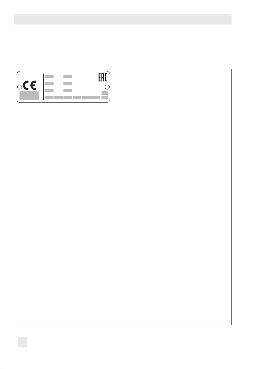
Fig.1: Valve nameplate
1…5 PED (Pressure Equipment Directive), "Art. 4, Abs. 3"
ID of the notied body, uid group, and category
6 Type designation
8 Material
9 Year of manufacture
10 Valve size:
DIN: DN · ANSI: NPS· JIS: DN…A/B
11 Pressure rating:
DIN: PN · ANSI: CL · JIS: K
12 Order no. with modication index
For after-sales service orders: AA prex
13 Position in order
For after-sales service orders: conguration ID
14 Flow coefcient:
· ANSI: CV · JIS: C
DIN: K
VS
V
15 Characteristic:
%: equal percentage · Lin: linear · NO/NC: quick opening
16 Seat-plug seal:
ME: metal (see section3.3)
HA: carbide metal
ST: Stellite
®
facing
KE: ceramic
PT: soft seal with PTFE
PK: soft seal with PEEK
17 Seat code (trim material) · On request
18 Pressure balancing:
DIN: D · ANSI: B · JIS: B
19 Flow divider:
1: ST1 · 3: ST3
AC trim:
AC-1 to AC-3
20 Country of origin
12 EB 8052 EN
Page 13
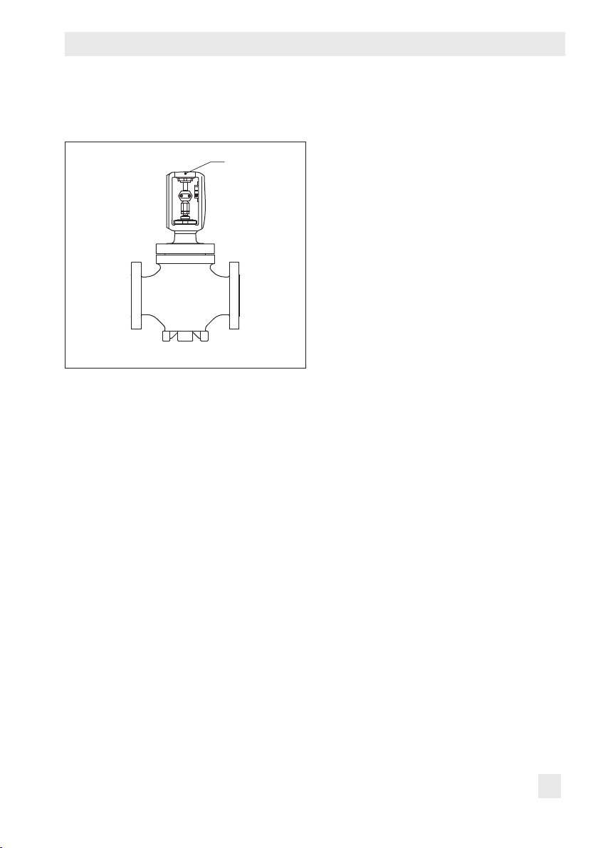
The nameplate (80) is afxed to the yoke of
80
the valve (see Fig.2).
Fig.2: Location of the nameplate
2.2 Actuator nameplate
See associated actuator documentation.
Markings on the control valve
2.3 Material number
The seat and plug of the valves have an article number written on them. Specifying this
article number, you can contact us to nd out
which material is used. Additionally, a seat
code is used to identify the trim material.
This seat code is specied on the nameplate
(17 on nameplate). For more details on the
nameplate, see section2.1.
EB 8052 EN 13
Page 14
Design and principle of operation
3 Design and principle of oper-
ation
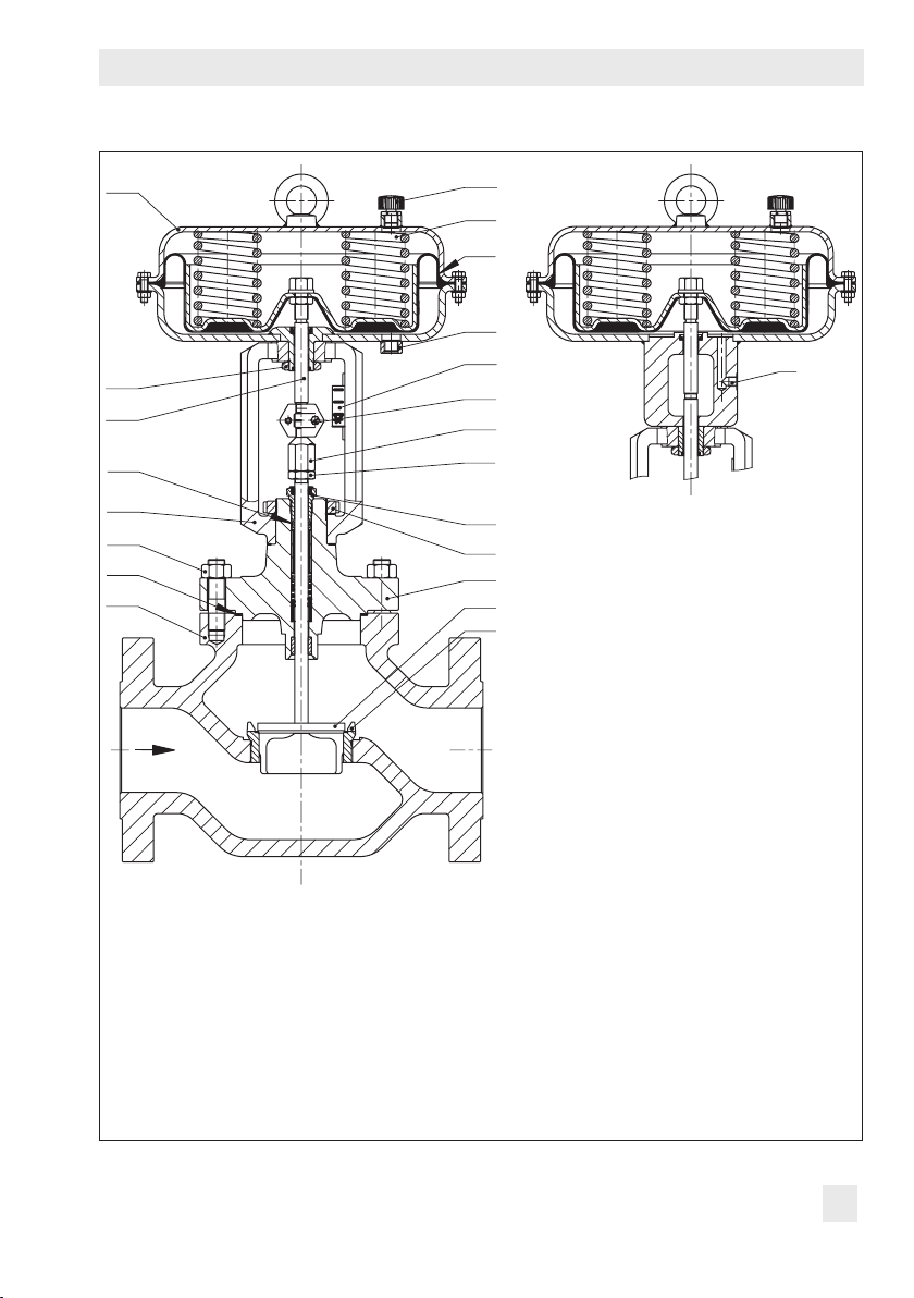
The single-seated Type3251 Globe Valve is
preferably combined with a SAMSON
Type3271 or Type3277 Pneumatic Actuator
(see Fig.3). It can also be combined with
other actuators.
The seat (4) and plug with plug stem (5) are
installed in the body (1). The plug stem is
connected to the actuator stem (A7) by the
stem connector clamps (A26) and is sealed
by a spring-loaded V-ring packing (15). The
springs in the pneumatic actuator (A) are located either above or below the diaphragm
(A4) depending on the selected fail-safe action (see section3.1). A change in the signal
pressure acting on the diaphragm causes the
plug to move. The actuator size is determined by the diaphragm area.
The medium ows through the valve in the
direction indicated by the arrow. A rise in
signal pressure causes the force acting on
the diaphragm in the actuator to increase.
The springs are compressed. Depending on
the selected direction of action, the actuator
stem retracts or extends. As a result, the plug
position in the seat changes and determines
the ow rate through the valve.
Actuator stem extends (FA)
When the signal pressure is reduced or the
air supply fails, the springs move the actuator stem downward and close the valve. The
valve opens when the signal pressure is increased enough to overcome the force exerted by the springs.
Actuator stem retracts (FE)
When the signal pressure is reduced or the
air supply fails, the springs move the actuator stem upwards and open the valve. The
valve closes when the signal pressure is increased enough to overcome the force exerted by the springs.
Tip
The actuator's direction of action can be reversed, if required. Refer to the mounting
and operating instructions of the pneumatic
actuator:
uEB8310‑X for Type3271 and Type3277
3.1 Fail-safe positions
The fail-safe position depends on the mounted actuator.
Depending on how the compression springs
are arranged in the pneumatic actuator, the
valve has two different fail-safe positions:
14 EB 8052 EN
Page 15
A16
A8
A7
15
Design and principle of operation
A
A10
A4
S
84
A26
9
10
S
14
17
3
1
8
92
2
5
4
1 Body
2 Bonnet
3 Yoke
4 Seat
5 Plug (with plug stem)
8 Threaded bushing
(packing nut)
9 Stem connector nut
10 Lock nut
14 Nut
15 Packing
17 Body gasket
84 Travel indicator scale
92 Castellated nut
A Actuator
A4 Diaphragm
A7 Actuator stem
A8 Ring nut
A10 Spring
A16 Vent plug
A26 Stem connector clamps
S Signal pressure
connection
Fig.3: Type3251 Valve with Type3271 Pneumatic Actuator (left) and Type3277 Pneumatic
Actuator (right)
EB 8052 EN 15
Page 16
Design and principle of operation
3.2 Versions
The modular design allows an insulating section or metal bellows to be tted to the standard valve version.
Actuators
In these instructions, the preferable combination with a Type3271 or Type3277 Pneumatic Actuator is described. The pneumatic
actuator (with or without handwheel) can be
replaced by another pneumatic actuator in a
different size, but with the same travel.
Î Observe the maximum permissible actu-
ator force.
Note
If the travel range of the actuator is larger
than the travel range of the valve, the spring
assembly in the actuator must be preloaded
so that the travel ranges match. See associated actuator documentation.
The basic pneumatic actuator can be replaced by a pneumatic actuator with additional handwheel or by an electric actuator.
Compliance
The Type3251 Valve bears both the CE and
EAC marks of conformity.
Temperature range
Depending on the version, the control valve
is designed for a temperature range from
–10 to +220°C (14 to 428°F). The use of
an insulating section or bellows seal extends
the temperature range from –196 to
+550°C (–325 to +1022°F).
Leakage class
Depending on the version, the following
leakage class applies:
Seal (16 on
nameplate)
Pressure balancing (18 on nameplate)
Leakage class
(according to
ANSI/FCI70-2)
ME, ST ME, ST PT, PK
– D/B –
Min. IV Min. IV VI
3.3 Technical data
The nameplates on the valve and actuator
provide information on the control valve version. See section2.1 and the associated actuator documentation.
Note
More information is available in Data Sheet
uT8052.
16 EB 8052 EN
Page 17

Noise emission
SAMSON is unable to make general
statements about noise emission as it
depends on the valve version, plant facilities,
and process medium. On request, SAMSON
can perform calculations according to
IEC60534, Part8-3 and Part8-4 or
VDMA24422 (edition 89).
!
WARNING
Risk of hearing loss or deafness due to loud
noise.
Wear hearing protection when working near
the valve.
Design and principle of operation
EB 8052 EN 17
Page 18

Design and principle of operation
Dimensions and weights
Table1 to Table3 provide a summary of the dimensions and weights of the standard version
of Type3251 Valve. The lengths and heights in the dimensional drawings are shown on
p.19.
Table1: Dimensions of Type3251 Valve, up to NPS6
Valve
Length L
(anges RF
and
welding
ends)
Height H4
H8 for
actuator
NPS ½ 1 1½ 2 3 4 6
DN 15 25 40 50 80 100 150
Class 150
Class 300
Class 600
Class 900
Class
1500
Class
2500
Class 150
to 600
Class 900
Class
1500 to
2500
350cm²
355cm²
700cm²
750cm²
in 7.25 7.25 8.75 10.00 11.75 13.88 17.75
mm 184 184 222 254 298 352 451
in 7.50 7.75 9.25 10.50 12.50 14.50 18.62
mm 190 197 235 267 318 368 473
in 8.00 8.25 9.88 11.25 13.25 15.50 20.00
mm 203 210 251 286 337 394 508
in 8.50 10.00 12.00 14.50 15.00 18.00 24.00
mm 216 254 305 368 381 457 610
in 8.50 10.00 12.00 14.50 18.50 21.50 27.75
mm 216 254 305 368 470 546 705
in 10.38 12.12 15.12 17.75 22.75 26.50 36.00
mm 264 308 384 451 578 673 914
in 5.98 5.98 6.46 8.54 8.74 9.53 12.36
mm 152 152 164 217 222 242 314
in 7.32 7.32 7.68 9.88 8.74 9.53 12.36
mm 186 186 195 251 222 242 314
in 7.32 7.32 7.68 9.88 11.34 13.7 18.35
mm 186 186 195 251 288 348 466
in 9.45 9.45 9.45 9.45 9.45 9.45
mm 240 240 240 240 240 240
in 9.45 9.45 9.45 9.45 9.45 9.45 16.46
mm 240 240 240 240 240 240 418
in 9.45 9.45 9.45 9.45 9.45 9.45 16.46
mm 240 240 240 240 240 240 418
in 9.45 9.45 9.45 9.45 9.45 9.45 16.46
mm 240 240 240 240 240 240 418
–
18 EB 8052 EN
Page 19

Design and principle of operation
H2
L
H4 H8
H2
L
H4 H8
Valve
H8 for
actuator
H2 (NPS4
and larger
with foot)
NPS ½ 1 1½ 2 3 4 6
DN 15 25 40 50 80 100 150
1000cm²
1400-
60cm²
1400-
120cm²
2800cm²
2x2800cm²
Class 150
Class 300
to 600
Class 900
Class
1500
Class
2500
Dimensional drawings
in
mm 295 295 295 418
in 11.61 11.61 11.61 16.46
mm 295 295 295 418
in 18.90 18.90 18.90 19.80
mm 480 480 480 503
in 18.90 18.90 18.90 19.80
mm 480 480 480 503
in 18.90 18.90 18.90 19.80
mm 480 480 480 503
in 1.97 2.36 3.05 3.54 3.94 6.3 8.66
mm 50 60 80 90 100 160 220
in 2.36 2.76 3.54 3.94 4.72 7.09 9.25
mm 60 70 90 100 120 180 235
in 2.76 3.05 3.94 4.33 4.72 7.09 9.25
mm 70 80 100 110 120 180 235
in 2.76 3.05 3.94 4.33 5.51 8.66 11.22
mm 70 80 100 110 140 220 285
in 2.95 3.54 4.33 4.72 6.3 9.33 12.6
mm 75 90 110 120 160 237 320
–
11.61 11.61 11.61 16.46
Type3251 up to NPS3 without foot Type3251 in NPS4 and larger with foot
EB 8052 EN 19
Page 20

Design and principle of operation
Table2: Dimensions of Type3251 Valve, NPS8 and larger
Valve
Length L
(anges RF
and
welding
ends)
Height H4
H8 for
actuator
NPS 8 10 12 14 16 20
DN 200 250 300 – 400 500
Class 150
Class 300
Class 600
Class 900
Class
1500
Class
2500
Class 150
to 600
Class 900
Class
1500 to
2500
350cm²
355cm²
700cm²
750cm²
in 21.38 26.50 29.00 35.00 40.00
mm 543 673 737 889 1016
in 22.38 27.88 30.50 36.50 41.62
mm 568 708 775 927 1057
in 24.00 29.62 32.25 38.25 43.62
mm 610 752 819 972 1108
in 29.00 33.00 38.00 40.50
mm 737 838 965 1029
in 32.75 39.00 44.50 49.50
mm 832 991 1130 1257
in 40.25
mm 1022
in 15.24 17.40
mm 387 442
in 15.24 20.43
mm 387 519
On request –
1)
25.79 25.20 25.20
1)
2)
655 640 640
2)
25.79
655
in 22.44
mm 570
On request
in
mm
in
mm
in 16.46 16.46
mm 418 418
in 16.46 16.46
mm 418 418
On request
On request
On request
On request
On request
On request
On request
Class 1500
On request
–
–
–
–
20 EB 8052 EN
Page 21

Design and principle of operation
Valve
H8 for
actuator
H2 (NPS4
and larger
with foot)
1)
NPS10, Class150 to 300: 17.40” or 442mm
2)
NPS10, Class600 to 900: 20.43” or 519mm
3)
H8= 25.59“ or 650mm with 250mm seat bore
NPS 8 10 12 14 16 20
DN 200 250 300 – 400 500
1000cm²
1400-
60cm²
1400-
120cm²
2800cm²
2x2800cm²
Class 150
Class 300
to 600
Class 900
Class
1500
Class
2500
in 16.46
mm 418
in 16.46
mm 418
in 19.80 19.80 25.59 25.59 25.59 25.59
mm 503 503
in 19.80 19.80 25.59 25.59 25.59 25.59
mm 503 503
in 19.80 19.80 25.59 25.59 25.59 25.59
mm 503 503
in 9.84 12.21 14.57
mm 250 310 370 415
in 10.63 11.82 15.35
mm 270 300 390
in
mm
in
mm
in
mm
On request
On request
3)
3)
3)
650 650 650 650
650 650 650 650
650 650 650 650
On request
16.34
On request
On request
On request
On request –
On request
EB 8052 EN 21
Page 22

Design and principle of operation
Table3: Weights for standard version of Type3251, up to NPS6
Valve NPS ½ 1 1½ 2 3 4 6
lbs 26 31 42 66 110 152 342
kg 12 14 19 30 50 69 155
lbs 33 35 57 95 170 247 694
kg 15 16 26 43 77 112 315
lbs 33 35 57 95 170 247 694
kg 15 16 26 43 77 112 315
lbs 33 35 57 95 170 247 694
kg 15 16 26 43 77 112 315
lbs
On re-
quest
kg 34 57 72 158 225 560
lbs
On re-
quest
kg 42 74 108 172 274 997
75 126 159 348 496 1235
93 163 238 379 604 2198
Valve
without
actuator
Class150
Class 300
Class 600
Class 900
Class 1500
Class 2500
Table4: Weights for standard version of Type3251 in NPS8 and larger
Valve NPS 8 10 12 14 16 20
Valve
without
actuator
Class150
Class 300
Class 600
Class 900
Class 1500
Class 2500
lbs 948 1892 2028
kg 430 858 920 1450 1650
lbs 948 1892 2028
kg 430 858 920 1450 1650
lbs 1096 1609 2535
kg 497 730 1150
lbs 1157 2844 3263
kg 525 1290 1480 2600
lbs 1949 4630
kg 884 2100
lbs 3990
kg 1810
On request –
On re-
quest
On re-
quest
On re-
quest
3197 3638
3197 3638
On request
5732
On request
On re-
quest
22 EB 8052 EN
Page 23

Design and principle of operation
Note
Refer to the following data sheets for more dimensions and weights:
uT8052 for valves with bellows seal, insulating section or heating jacket
The associated actuator documentation applies to actuators, e.g. for SAMSON pneumatic
actuators:
uT8310‑1 for Type3271 and Type3277 Actuators up to 750cm² actuator area
uT8310‑2 for Type3271 Actuator with 1000cm² actuator area and larger
uT8310‑3 for Type3271 Actuator with 1400‑60cm² actuator area
EB 8052 EN 23
Page 24

Measures for preparation
4 Measures for preparation
After receiving the shipment, proceed as follows:
1. Check the scope of delivery. Compare
the shipment received against the delivery note.
2. Check the shipment for transportation
damage. Report any damage to
SAMSON and the forwarding agent
(refer to delivery note).
4.1 Unpacking
Note
Do not remove the packaging until immediately before installing the valve into the pipeline.
Proceed as follows to lift and install the
valve:
1. Remove the packaging from the valve.
2. Dispose of the packaging in accordance
with the valid regulations.
4.2 Transporting and lifting
!
DANGER
Hazard due to suspended loads falling.
Stay clear of suspended or moving loads.
!
WARNING
Risk of lifting equipment tipping and risk of
damage to lifting accessories due to exceed-
ing the rated lifting capacity.
− Only use approved lifting equipment and
accessories whose minimum lifting
capacity is higher than the weight of the
valve (including actuator, if applicable).
− Refer to section3.3 or Data Sheet
uT8052 for weights.
!
WARNING
Risk of personal injury due to control valve
tipping.
− Observe the valve's center of gravity.
− Secure the valve against tipping over or
turning.
!
NOTICE
Risk of valve damage due to foreign particles entering the valve.
The protective caps tted on the valve's inlet
and outlet prevent foreign particles from entering the valve and damaging it.
Do not remove the protective caps until im-
mediately before installing the valve into the
pipeline.
24 EB 8052 EN
Page 25

Measures for preparation
!
NOTICE
Risk of valve damage due to incorrectly attached slings.
The welded‑on lifting eyelet on SAMSON
actuators is only intended for mounting and
removing the actuator as well as lifting the
actuator without valve. Do not use this lifting
eyelet to lift the entire control valve assembly.
− When lifting the control valve, make sure
that the slings attached to the valve body
bear the entire load.
− Do not attach load-bearing slings to the
actuator, handwheel or any other parts.
− Observe lifting instructions (see sec-
tion4.2.2).
Tip
SAMSON's After‑sales Service department
can provide more detailed transport and lifting instructions on request.
4.2.1 Transporting
The control valve can be transported using
lifting equipment (e.g. crane or forklift).
Î Leave the control valve in its transport
container or on the pallet to transport it.
Î Observe the transport instructions.
Transport instructions
− Protect the control valve against external
inuences (e.g. impact).
− Do not damage the corrosion protection
(paint, surface coatings). Repair any
damage immediately.
− Protect the control valve against moisture
and dirt.
− The permissible transportation tempera-
ture of standard control valves is –20 to
+65°C (–4 to +149°F).
Note
Contact SAMSON's After‑sales Service department for the transportation temperatures
of other valve versions.
4.2.2 Lifting
To install a large valve into the pipeline, use
lifting equipment (e.g. crane or forklift) to lift
it.
Lifting instructions
− Secure slings against slipping.
− Make sure the slings can be removed
from the valve once it has been installed
into the pipeline.
EB 8052 EN 25
Page 26

Measures for preparation
− Prevent the control valve from tilting or
tipping.
− Do not leave loads suspended when in-
terrupting work for longer periods of
time.
− Make sure that the axis of the pipeline is
always horizontal during lifting and the
axis of the plug stem is always vertical.
− Make sure that the additional sling be-
tween the lifting eyelet and rigging
equipment (hook, shackle etc.) does not
bear any load when lifting valves larger
than NPS6. The sling only protects the
control valve from tilting while being lift-
ed. Before lifting the control valve, tighten the sling.
Fig.4: Lifting points on the control valve: up to NPS6 (left) and with welding ends (middle) · NPS6
and larger with additional lifting eyelet on the actuator (right)
26 EB 8052 EN
Page 27

Measures for preparation
Version with anges
1. Attach one sling to each ange of the
body and to the rigging equipment (e.g.
hook) of the crane or forklift (see Fig.4).
2. NPS6 and larger: Attach another sling
to the lifting eyelet on the actuator and to
the rigging equipment.
3. Carefully lift the control valve. Check
whether the lifting equipment and accessories can bear the weight.
4. Move the control valve at an even pace
to the site of installation.
5. Install the valve into the pipeline (see section5.2).
6. After installation in the pipeline, check
whether the anges are bolted tight and
the valve in the pipeline holds.
7. Remove slings.
Version with welding ends
1. Attach one sling to each welding end of
the body and to the rigging equipment
(e.g. hook) of the crane or forklift (see
Fig.4).
2. Secure the slings attached to the body
against slipping using a connector.
3. NPS6 and larger: Attach another sling
to the lifting eyelet on the actuator and to
the rigging equipment.
4. Carefully lift the control valve. Check
whether the lifting equipment and accessories can bear the weight.
5. Move the control valve at an even pace
to the site of installation.
6. Install the valve into the pipeline (see section5.2).
7. After installation in the pipeline, check
whether the weld seams hold.
8. Remove slings.
Tip
We recommend using a hook with safety latch (see Fig.4). The safety latch prevents the
slings from slipping during lifting and transporting.
EB 8052 EN 27
Page 28

Measures for preparation
4.3 Storage
!
NOTICE
Risk of valve damage due to improper storage.
− Observe storage instructions.
− Avoid long storage times.
− Contact SAMSON in case of different
storage conditions or long storage periods.
Note
We recommend regularly checking the control valve and the prevailing storage conditions during long storage periods.
Storage instructions
− Protect the control valve against external
inuences (e.g. impact).
− Do not damage the corrosion protection
(paint, surface coatings). Repair any
damage immediately.
− Protect the control valve against moisture
and dirt. Store it at a relative humidity of
less than 75%. In damp spaces, prevent
condensation. If necessary, use a drying
agent or heating.
− Make sure that the ambient air is free of
acids or other corrosive media.
− The permissible storage temperature of
standard control valves is –20 to +65°C
(–4 to +149°F).
Note
Contact SAMSON's After‑sales Service
department for the storage temperatures of
other valve versions.
− Do not place any objects on the control
valve.
Special storage instructions for elastomers
Elastomer, e.g. actuator diaphragm
− To keep elastomers in shape and to pre-
vent cracking, do not bend them or hang
them up.
− We recommend a storage temperature of
15°C (59°F) for elastomers.
− Store elastomers away from lubricants,
chemicals, solutions, and fuels.
Tip
SAMSON's After‑sales Service department
can provide more detailed storage instructions on request.
28 EB 8052 EN
Page 29

4.4 Preparation for installation
Proceed as follows:
Î Flush the pipelines.
Note
The plant operator is responsible for cleaning the pipelines in the plant.
Î Check the valve to make sure it is clean.
Î Check the valve for damage.
Î Check to make sure that the type desig-
nation, valve size, material, pressure rating, and temperature range of the valve
match the plant conditions (size and
pressure rating of the pipeline, medium
temperature etc.).
Î For steam applications, make sure that
the pipelines are dry. Moisture will damage the inside of the valve.
Î Check any mounted pressure gauges to
make sure they function.
Î When the valve and actuator are al-
ready assembled, check the tightening
torques of the bolted joints
(uWA0029). Components may loosen
during transport.
Measures for preparation
EB 8052 EN 29
Page 30

Mounting and start-up
5 Mounting and start-up
SAMSON valves are delivered ready for
use. In special cases, the valve and actuator
are delivered separately and must be assembled on site. The procedure to mount and
start up the valve are described in the following.
!
NOTICE
Risk of valve damage due to excessively high
or low tightening torques.
Observe the specied torques on tightening
control valve components. Excessively tightened torques lead to parts wearing out
quicker. Parts that are too loose may cause
leakage.
Observe the specied tightening torques
(uWA0029).
!
NOTICE
Risk of valve damage due to the use of unsuitable tools.
Only use tools approved by SAMSON
(uWA0029).
5.1 Mounting the actuator onto the valve
Proceed as described in the actuator documentation if the valve and actuator have not
been assembled by SAMSON.
Versions with V-port plug
Each V-port plug has three V-shaped ports.
Depending on the valve size, the size of the
symmetrically arranged V-shaped ports varies. The process medium in the valve ows
through the V-shaped ports as soon as the
plug is lifted out of the seat (i.e. the valve
opens).
1. Before mounting the actuator, determine
which V-shaped port is uncovered rst
when the plug is lifted out of the seat.
Tip
Usually, this is the largest V‑shaped port.
2. On mounting the actuator, make sure
that the V-shaped port uncovered rst
faces toward the valve outlet.
!
NOTICE
Risk of damage to the wall of the valve body
due to incorrectly diverted jet stream.
The process medium cannot ow unobstructed through the valve when the V‑port
plug has been installed incorrectly. This will
result in the process medium hitting the body
wall, which may lead to severe valve dam-
age.
Make sure the V-port plug is installed
correctly.
30 EB 8052 EN
Page 31

Mounting and start-up
Note
− Remove the mounted actuator before
mounting the other actuator (see associated actuator documentation).
− Preloading the actuator springs increases
the thrust of a pneumatic actuator and re-
duces the travel range of the actuator (see
associated actuator documentation).
5.2 Installing the valve into the pipeline
5.2.1 Checking the installation
conditions
Pipeline routing
The inlet and outlet lengths vary depending
on the process medium. To ensure the control
valve functions properly, follow the installation instructions given below:
Î Observe the inlet and outlet lengths (see
Table5). Contact SAMSON if the valve
conditions or state of the medium process
deviate.
Î Install the valve free of stress and with the
least amount of vibrations as possible. If
necessary, attach supports to the valve.
Î Install the valve allowing sufcient space
to remove the actuator and valve or to
perform service and repair work on
them.
Mounting position
Generally, we recommend installing the
valve with the actuator upright and on top of
the valve.
In the following versions, the valve must be
installed with the actuator on top:
− Valves in NPS4 and larger
− Valves with insulating section for low
temperatures below –10°C (14°F)
Î Contact SAMSON if the mounting posi-
tion is not as specied above.
Support or suspension
Depending on the valve version and mounting position, the control valve and pipeline
must be supported or suspended. The plant
engineering company is responsible in this
case.
!
NOTICE
Premature wear and leakage due to insufcient support or suspension.
In the following versions, the control valve
must be supported or suspended:
− Valves that are not installed with the actua-
tor in the upright position on top of the
valve.
Attach a suitable support or suspension to
the valve.
Vent plugs
Vent plugs are screwed into the exhaust air
ports of pneumatic and electropneumatic devices. They ensure that any exhaust air that
forms can be vented to the atmosphere (to
avoid excess pressure in the device). Further-
EB 8052 EN 31
Page 32

Mounting and start-up
Q
Table5: Inlet and outlet lengths
a x NPS b x NPS
Q Flow rate
a Inlet length
b Outlet length
State of process
medium
Gas
Vapor
Liquid
Flashing – 2 20
Multi-phase – 10 20
1)
No saturated steam
more, the vent plugs allow air intake to prevent a vacuum from forming in the device.
Î Locate the vent plug on the opposite side
to the workplace of operating personnel.
Î On mounting valve accessories, make
Valve conditions
Ma≤0.3 2 4
0.3≤Ma≤0.7 2 10
Ma≤0.3
0.3≤Ma≤0.7
Saturated steam (percentage of condensate
>5%)
Free of cavitation/w<10m/s 2 4
Cavitation producing noise/w≤3m/s 2 4
Cavitation producing noise/3<w<5m/s 2 10
Critical cavitation/w≤3m/s 2 10
Critical cavitation/3<w<5m/s 2 20
1)
1)
Note
The workplace of operating personnel is the
location from which the valve, actuator, and
any mounted valve accessories can be ac-
cessed to operate them.
Inlet length aOutlet length
2 4
2 10
2 20
sure that they can be operated from the
workplace of the operating personnel.
b
32 EB 8052 EN
Page 33

Mounting and start-up
5.2.2 Additional ttings
Strainers
We recommend installing a SAMSON
strainer upstream of the valve. It prevents solid particles in the process medium from
damaging the valve.
Bypass and shut-off valves
We recommend installing a shut-off valve
both upstream of the strainer and downstream of the valve and installing a bypass
line. The bypass ensures that the plant does
not need to be shut down for service and repair work on the valve.
Insulation
Only insulate control valves with insulating
section or bellows seal up to the bonnet
ange of the valve body for medium temperatures below 0°C (32°F) and above
220°C (428°F).
Do not insulate valves mounted to comply
with NACE MR0175 requirements.
Test connection
Versions with bellows seal tted with a test
connection (G
sealing ability of the bellows to be monitored.
Particularly for liquids and vapors, we recommend installing a suitable leakage indicator (e.g. a contact pressure gauge, an outlet
to an open vessel or an inspection glass).
1
/
8
) at the top ange allow the
!
WARNING
Risk of personal injury due to pressurized
components and process medium escaping
under pressure.
Do not loosen the screw of the test connection while the valve is in operation.
Safety guard
To reduce the crush hazard arising from
moving parts (actuator and plug stem), a
safety guard can be installed.
Noise emission
Trims with ow dividers can be used to reduce noise emission (see uT8081).
5.2.3 Installing the control valve
Version with anges
1. Close the shut-off valve in the pipeline
while the valve is being installed.
2. Remove the protective caps from the
valve ports before installing the valve.
3. Lift the valve using suitable lifting equip-
ment to the site of installation (see section4.2.2). Observe the ow direction
through the valve. The arrow on the
valve indicates the direction of ow.
4. Make sure that the correct ange gaskets
are used.
5. Bolt the pipe to the valve free of stress.
6. Depending on the eld of application,
allow the valve to cool down or heat up
EB 8052 EN 33
Page 34

Mounting and start-up
to reach ambient temperature before
start up.
7. Slowly open the shut-off valve in the
pipeline after the valve has been installed.
!
NOTICE
Risk of valve damage due to a sudden pressure increase and resulting high ow velocities.
Slowly open the shut‑off valve in the pipeline
during start-up.
8. Check the valve to ensure it functions
properly.
Version with welding ends
1. Proceed as described for Version with
anges (steps 1 to 3).
2. Completely retract the actuator stem to
protect the plug from sparks during welding.
3. Weld the valve free of stress into the
pipeline.
4. Proceed as described for Version with
anges (steps 6 to 8).
5.3 Quick check
SAMSON valves are delivered ready for
use. To test the valve's ability to function, the
following quick checks can be performed:
Leakage
1. Close the valve.
2. Slowly open the shut-off valve in the
pipeline.
!
NOTICE
Risk of valve damage due to a sudden pressure increase and resulting high ow velocities.
Slowly open the shut‑off valve in the pipeline
during start-up.
3. Check the valve for leakage (visual inspection).
Travel motion
The movement of the actuator stem must be
linear and smooth.
Î Open and close the valve, observing the
movement of the actuator stem.
Î Apply the maximum and minimum con-
trol signals to check the end positions of
the valve.
Î Check the travel reading at the travel in-
dicator scale.
34 EB 8052 EN
Page 35

Mounting and start-up
Fail-safe position
Î Shut off the signal pressure line.
Î Check whether the valve moves to the
fail-safe position.
Adjustable packing
Tip
A label on the ange (2) indicates whether
an adjustable packing is installed.
1. Tighten the threaded bushing gradually
(by turning it clockwise) until the packing
seals the valve.
!
NOTICE
Risk of valve damage due to the threaded
bushing tightened too far.
Make sure that the plug stem can still move
smoothly after the threaded bushing has
been tightened.
2. Open and close the valve several times.
3. Check the valve for leakage (visual inspection).
4. Repeat steps 1 and 2 until the packing
completely seals the valve.
Pressure test
During the pressure test, make sure the following conditions are met:
− Retract the plug stem to open the valve.
− Observe the maximum permissible pres-
sure for valve and plant.
Note
The plant operator is responsible for
performing the pressure test. SAMSON's
After‑sales Service department can support
you to plan and perform a pressure test for
your plant.
Note
If the adjustable packing does not seal properly, contact SAMSON's After‑sales Service
department.
EB 8052 EN 35
Page 36

Operation
6 Operation
Immediately after completing mounting and
start-up (see section5), the valve is ready for
use.
!
WARNING
Crush hazard arising from moving parts (actuator and plug stem).
Do not insert hands or ngers into the yoke
while the valve is in operation.
!
WARNING
Risk of personal injury when the actuator
vents.
Wear eye protection when working in close
proximity to the control valve.
!
WARNING
Risk of burn injuries due to hot or cold components and pipelines.
Depending on the process medium, valve
components, and pipelines may get very hot
or cold and cause burn injuries.
Wear protective clothing and safety gloves.
6.1 Working in manual mode
Valves tted with actuators with a handwheel
can be manually closed or opened in case of
supply air failure.
Î For normal closed-loop operation, move
the handwheel to the neutral position.
!
NOTICE
Operation disturbed by a blocked actuator
or plug stem.
Do not impede the movement of the actuator
or plug stem by inserting objects into their
path.
36 EB 8052 EN
Page 37

EB 8052 EN 37
Page 38

Servicing
7 Servicing
The control valve is subject to normal wear,
especially at the seat, plug, and packing.
Depending on the operating conditions,
check the valve at regular intervals to prevent possible failure before it can occur.
Tip
SAMSON's After‑sales Service department
can support you to draw up an inspection
plan for your plant.
We recommend removing the valve from the
pipeline for service or repair work (see section9.2).
!
DANGER
Risk of bursting in pressure equipment.
Control valves and pipelines are pressure
equipment. Improper opening can lead to
bursting of the valve.
− Before starting any work on the control
valve, depressurize all plant sections con-
cerned as well as the valve.
− Drain the process medium from all the
plant sections concerned as well as the
valve.
− Wear personal protective equipment.
!
WARNING
Risk of personal injury due to residual process medium in the valve.
While working on the valve, residual process
medium can escape and, depending on its
properties, may lead to personal injury, e.g.
(chemical) burns.
Wear protective clothing, safety gloves, and
eyewear.
!
WARNING
Risk of burn injuries due to hot or cold components and pipeline.
Valve components and the pipeline may become very hot or cold. Risk of burn injuries.
− Allow components and pipelines to cool
down or heat up.
− Wear protective clothing and safety gloves.
!
NOTICE
Risk of valve damage due to incorrect servicing or repair.
Service and repair work must only be performed by trained staff.
!
NOTICE
Risk of valve damage due to excessively high
or low tightening torques.
Observe the specied torques on tightening
control valve components. Excessively tightened torques lead to parts wearing out
quicker. Parts that are too loose may cause
leakage.
Observe the specied tightening torques
(uWA0029).
!
NOTICE
Risk of valve damage due to the use of unsuitable tools.
Only use tools approved by SAMSON
(uWA0029).
38 EB 8052 EN
Page 39

Servicing
!
NOTICE
Risk of valve damage due to the use of unsuitable lubricants.
Only use lubricants approved by SAMSON
(see parts list).
Note
The control valve was checked by SAMSON
before it left the factory.
− Certain test results (seat leakage and leak
test) certied by SAMSON lose their validity when the valve body or actuator hous-
ing is opened.
− The product warranty becomes void if ser-
vice or repair work not described in these
instructions is performed without prior
agreement by SAMSON's After‑sales Ser-
vice department.
− Only use original spare parts by SAM-
SON, which comply with the original specications.
7.1 Replacing the gasket
!
NOTICE
Risk of control valve damage due to incorrect
service or repair.
The gasket can only be replaced when all the
following conditions are met:
− The valve size is ≤NPS4.
− The valve does not have a balanced plug.
− The valve does not have a ow divider.
To replace the gasket in other valve versions,
contact SAMSON's After‑sales Service department.
7.1.1 Standard version
1. Remove the actuator from the valve. See
associated actuator documentation.
2. Undo the body nuts (14) gradually in a
crisscross pattern.
3. Lift the ange (2) and plug with plug
stem (5) off the body (1).
4. Remove the gasket (17). Carefully clean
the sealing faces in the valve body (1)
and on the ange (2).
5. Insert a new gasket (17) into the body.
6. Place the ange (2) onto the body.
Version with V-port plug: place the
ange (2) onto the valve body, making
sure that the largest V-shaped port of the
V-port plug faces toward the valve outlet.
See section5.1.
7. Firmly press the plug (5) into the seat (4).
Fasten down the ange (2) with the body
nuts (14). Tighten the nuts gradually in a
EB 8052 EN 39
Page 40

Servicing
92
3
15
14
17
1
5
10
9
10
8
92
3
9
15
21
8
2
7
4
7
14
17
4
5
1 Body
2 Flange
3 Yo k e
4 Seat
5 Plug (with plug stem)
7 Guide bushing
8 Threaded bushing
(packing nut)
9 Stem connector nut
10 Lock nut
14 Nut
15 Packing
17 Body gasket
21 Insulating section
92 Castellated nut
Fig.5: Standard version of Type3251 with Type3271 Actuator (left) and Type3251 in version with
insulating section (right)
40 EB 8052 EN
Page 41

Servicing
crisscross pattern. Observe tightening
torques.
8. Mount actuator. See associated actuator
documentation.
9. Adjust lower or upper signal bench
range. See associated actuator documentation.
7.1.2 Version with insulating
section or bellows seal
1. Remove the actuator from the valve. See
associated actuator documentation.
2. Undo the body nuts (14) gradually in a
crisscross pattern.
3. Lift the insulating section (21) and plug
with plug stem (5) off the body (1).
4. Remove the gasket (17). Carefully clean
the sealing faces in the valve body (1)
and on the insulating section (21).
5. Insert a new gasket (17) into the body.
6. Place the insulating section (21) onto the
body.
Version with V-port plug: place the insulating section (21) onto the valve body,
making sure that the largest V-shaped
port of the V-port plug faces toward the
valve outlet. See section5.1.
7. Firmly press the plug (5) into the seat (4).
Fasten down the insulating section (21)
with the body nuts (14). Tighten the nuts
gradually in a crisscross pattern. Observe tightening torques.
8. Mount actuator. See associated actuator
documentation.
9. Adjust lower or upper signal bench
range. See associated actuator documentation.
7.2 Replacing the packing
!
NOTICE
Risk of control valve damage due to incorrect
service or repair.
The packing can only be replaced when all
the following conditions are met:
− The valve size is ≤NPS4.
− The valve does not have a balanced plug.
− The valve does not have a bellows seal.
− The standard or ADSEAL packing is in-
stalled in the valve.
To replace the packing in other valve ver-
sions, contact SAMSON's After‑sales Service
department.
7.2.1 Standard version
Standard packing (PTFE)
1. Remove the actuator from the valve. See
associated actuator documentation.
2. Unscrew the castellated nut (92) and lift
the yoke (3) off the ange (2).
3. Undo the body nuts (14) gradually in a
crisscross pattern.
4. Lift the ange (2) and plug with plug
stem (5) off the body (1).
5. Unthread the stem connector nut (9) and
lock nut (10) from the plug stem.
6. Unscrew the threaded bushing (8).
EB 8052 EN 41
Page 42

Servicing
7. Pull the plug with plug stem (5) out of the
ange (2).
8. Pull all the packing parts out of the packing chamber using a suitable tool.
9. Renew damaged parts. Clean the packing chamber thoroughly.
10. Apply a suitable lubricant to all the packing parts and to the plug stem (5).
11. Slide the plug with plug stem (5) into the
ange (2).
12. Place the ange (2) together with the
plug stem and plug (5) onto the body.
Version with V-port plug: place the
ange (2) onto the valve body, making
sure that the largest V-shaped port of the
V-port plug faces toward the valve outlet.
See section5.1.
13. Carefully slide the packing parts over the
plug stem into the packing chamber using a suitable tool. Observe the proper
sequence (see Fig.6).
14. Firmly press the plug (5) into the seat (4).
Fasten down the ange (2) with the body
nuts (14). Tighten the nuts gradually in a
crisscross pattern. Observe tightening
torques.
15. Screw in the threaded bushing (8) and
tighten it. Observe tightening torques.
16. Place yoke (3) on the ange (2) and fasten tight using the castellated nut (92).
17. Loosely screw the lock nut (10) and stem
connector nut (9) onto the plug stem.
18. Mount actuator. See associated actuator
documentation.
19. Adjust lower or upper signal bench
range. See associated actuator documentation.
ADSEAL packing
1. Proceed as described in Standard packing (PTFE), steps1 to 12.
2. Carefully slide the packing parts over the
plug stem into the packing chamber using a suitable tool. Observe the proper
sequence (see Fig.7).
3. Slide the seals (15.2) over the plug stem.
Insert the wire of the red spacer ring
(15.1) into the groove of the retaining
ring.
Slide the retaining ring over the plug
stem.
4. Insert the red spacer ring (15.1) between
the threaded bushing (8) and retaining
ring. See Fig.7.
5. Proceed as described in Standard packing (PTFE), steps14 to 19.
42 EB 8052 EN
Page 43

8
8
16
12
16
12
19
12
16
12
11
12
19
Fig.6: Standard packing: NPS½ to 1½ (left) and NPS2 to 4 (right)
12
19
12
16
12
11
12
19
Servicing
8 Threaded bushing
11 Spring
12 Washer
16 Packing ring
19 Spacer
7.2.2 Version with insulating section
6. Unscrew the threaded bushing (8).
7. Pull the plug with plug stem (5) out of the
insulating section (21).
Standard packing (PTFE)
1. Remove the actuator from the valve. See
associated actuator documentation.
2. Unscrew the castellated nut (92) and lift
the yoke (3) off the insulating section
(21).
3. Undo the body nuts (14) gradually in a
crisscross pattern.
4. Lift the insulating section (21) and plug
with plug stem (5) off the body (1).
5. Unthread the stem connector nut (9) and
8. Pull all the packing parts out of the packing chamber using a suitable tool.
9. Renew the damaged parts and carefully
clean the packing chamber.
10. Apply a suitable lubricant to all the packing parts and to the plug stem (5).
11. Slide the plug with plug stem (5) into the
insulating section (21).
12. Place the insulating section (21) together
with the plug stem and plug (5) onto the
body.
lock nut (10) from the plug stem.
EB 8052 EN 43
Page 44

Servicing
8
8
8 Threaded bushing
11 Spring
12 Washer
15 Packing (entire)
15.1 Shim with retaining ring
15.1
12
18
15.2
16
18
19
12
16
12
11
12
19
15
15.1
15.2
16
12
15
19
12
16
12
11
12
19
15.2 Seal
16 Packing ring
18 Bushing
19 Spacer
Fig.7: ADSEAL packing: NPS½ to 1½ (left) and NPS2 to 4 (right)
44 EB 8052 EN
Page 45

Servicing
Version with V-port plug: place the insulating section (21) onto the valve body,
making sure that the largest V-shaped
port of the V-port plug faces toward the
valve outlet. See section5.1.
13. Carefully slide the packing parts over the
plug stem into the packing chamber using a suitable tool. Observe the proper
sequence (see Fig.6).
14. Firmly press the plug (5) into the seat (4).
Fasten down the insulating section (21)
with the body nuts (14). Tighten the nuts
gradually in a crisscross pattern. Observe tightening torques.
15. Screw in the threaded bushing (8) and
tighten it. Observe tightening torques.
16. Place yoke (3) on the insulating section
(21) and fasten tight using the castellated
nut (92).
17. Loosely screw the lock nut (10) and stem
connector nut (9) onto the plug stem.
18. Mount actuator. See associated actuator
documentation.
19. Adjust lower or upper signal bench
range. See associated actuator documentation.
ADSEAL packing
1. Proceed as described in Standard packing (PTFE), steps1 to 12.
2. Carefully slide the packing parts over the
plug stem into the packing chamber using a suitable tool. Observe the proper
sequence (see Fig.7).
3. Slide the seals (15.2) over the plug stem.
Insert the wire of the red spacer ring
(15.1) into the groove of the retaining
ring.
Slide the retaining ring over the plug
stem.
4. Insert the red spacer ring (15.1) between
the threaded bushing (8) and retaining
ring. See Fig.7.
5. Proceed as described in Standard packing (PTFE), steps14 to 19.
7.3 Replacing the seat and
plug
!
NOTICE
Risk of control valve damage due to incorrect
service or repair.
Seat and plug can only be replaced when all
the following conditions are met:
− The valve size is ≤NPS4.
− The valve does not have a balanced plug.
− The valve does not have a bellows seal.
− The valve does not have a ow divider.
− The valve does not have a AC trim.
− The standard or ADSEAL packing is in-
stalled in the valve.
To replace seat and plug in other valve ver-
sions, contact SAMSON's After‑sales Service
department.
!
NOTICE
Risk of damage to the facing of the seat and
plug due to incorrect service or repair.
Always replace both the seat and plug.
EB 8052 EN 45
Page 46

Servicing
92
3
15
14
17
1
5
10
9
10
8
92
3
9
15
21
8
2
7
4
7
14
17
4
5
1 Body
2 Flange
3 Yo k e
4 Seat
5 Plug (with plug stem)
7 Guide bushing
8 Threaded bushing
(packing nut)
9 Stem connector nut
10 Lock nut
14 Nut
15 Packing
17 Body gasket
21 Insulating section
92 Castellated nut
Fig.8: Standard version of Type3251 with Type3271 Actuator (left) and Type3251 in version with
insulating section (right)
46 EB 8052 EN
Page 47

Servicing
Tip
When replacing the seat and plug, we also
recommend replacing the packing. See sec-
tion7.2.
7.3.1 Standard version
1. Remove the actuator from the valve. See
associated actuator documentation.
2. Unscrew the castellated nut (92) and lift
the yoke (3) off the ange (2).
3. Undo the body nuts (14) gradually in a
crisscross pattern.
4. Lift the ange (2) and plug with plug
stem (5) off the body (1).
5. Replace the gasket as described in section7.1.1.
6. Unthread the stem connector nut (9) and
lock nut (10) from the plug stem.
7. Unscrew the threaded bushing (8).
8. Pull the plug with plug stem (5) out of the
ange (2).
9. Pull all the packing parts out of the packing chamber using a suitable tool.
10. Make sure that the guide bushing (7) is
not damaged. If necessary, replace the
guide bushing using a suitable tool.
11. Unscrew the seat (4) using a suitable
tool.
12. Apply a suitable lubricant to the thread
and the sealing cone of the new seat.
13. Screw in the seat (4). Observe tightening
torques.
14. Apply a suitable lubricant to all the packing parts and to the new plug stem (5).
We recommend replacing the packing as
well. See section7.2.1.
15. Slide the new plug with plug stem (5) into the ange (2).
16. Place the ange (2) together with the
plug stem and plug (5) onto the body
(1).
Version with V-port plug: place the
ange (2) onto the valve body, making
sure that the largest V-shaped port of the
V-port plug faces toward the valve outlet.
See section5.1.
17. Carefully slide the packing parts over the
plug stem into the packing chamber using a suitable tool. Observe the proper
sequence (see Fig.6).
18. Firmly press the plug (5) into the seat (4).
Fasten down the ange (2) with the body
nuts (14). Tighten the nuts gradually in a
crisscross pattern. Observe tightening
torques.
19. Screw in the threaded bushing (8) and
tighten it. Observe tightening torques.
20. Place yoke (3) on the ange (2) and fasten tight using the castellated nut (92).
21. Loosely screw the lock nut (10) and stem
connector nut (9) onto the plug stem.
22. Mount actuator. See associated actuator
documentation.
23. Adjust lower or upper signal bench
range. See associated actuator documentation.
EB 8052 EN 47
Page 48

Servicing
7.3.2 Version with insulating section
1. Remove the actuator from the valve. See
associated actuator documentation.
2. Unscrew the castellated nut (92) and lift
the yoke (3) off the insulating section
(21).
3. Undo the body nuts (14) gradually in a
crisscross pattern.
4. Lift the insulating section (21) together
with the plug stem and plug (5) off the
body (1).
5. Replace the gasket as described in sec-
tion7.1.2.
6. Unthread the stem connector nut (9) and
lock nut (10) from the plug stem (5).
7. Unscrew the threaded bushing (8).
8. Pull the plug with plug stem (5) out of the
insulating section (21).
9. Pull all the packing parts out of the pack-
ing chamber using a suitable tool.
10. Make sure that the guide bushing (7) is
not damaged. If necessary, replace the
guide bushing using a suitable tool.
11. Unscrew the seat (4) using a suitable
tool.
12. Apply a suitable lubricant to the thread
and the sealing cone of the new seat.
13. Screw in the seat (4). Observe tightening
torques.
14. Apply a suitable lubricant to all the pack-
ing parts and to the new plug stem (5).
We recommend replacing the packing as
well. See section7.2.2.
15. Slide the new plug with plug stem (5) into the insulating section (21).
16. Place the insulating section (21) together
with the plug stem and plug (5) onto the
body (1).
Version with V-port plug: place the insulating section (21) onto the valve body,
making sure that the largest V-shaped
port of the V-port plug faces toward the
valve outlet. See section5.1.
17. Carefully slide the packing parts over the
plug stem extension into the packing
chamber using a suitable tool. Observe
the proper sequence (see Fig.6).
18. Firmly press the plug (5) into the seat (4).
Fasten down the insulating section (21)
with the body nuts (14). Tighten the nuts
gradually in a crisscross pattern. Observe tightening torques.
19. Screw in the threaded bushing (8) and
tighten it. Observe tightening torques.
20. Place yoke (3) on the insulating section
(21) and fasten tight using the castellated
nut (92).
21. Loosely screw the lock nut (10) and stem
connector nut (9) onto the plug stem.
22. Mount actuator. See associated actuator
documentation.
23. Adjust lower or upper signal bench
range. See associated actuator documentation.
48 EB 8052 EN
Page 49

Servicing
7.4 Preparation for return shipment
Defective valves can be returned to
SAMSON for repair.
Proceed as follows to return valves to
SAMSON:
1. Put the control valve out of operation (see
section9).
2. Decontaminate the valve. Remove any
residual process medium.
3. Fill in the Declaration on Contamination,
which can be downloaded from our
website at uwww.samson.de > Services
> Check lists for after sales service >
Declaration on Contamination.
4. Send the valve together with the lled-in
form to your nearest SAMSON subsidiary. SAMSON subsidiaries are listed on
our website at uwww.samson.de >
Contact.
7.5 Ordering spare parts and operating supplies
Tools
Details on suitable tools can be found in the
document uWA0029.
Contact your nearest SAMSON subsidiary
or the SAMSON After-sales Service department for information on spare parts, lubricants, and tools.
Spare parts
See section10.3 for details on spare parts.
Lubricant
Details on suitable lubricants can be found in
the parts list.
EB 8052 EN 49
Page 50

Malfunctions
8 Malfunctions
Depending on the operating conditions, check the valve at certain intervals to prevent possible failure before it can occur. Operators are responsible for drawing up an inspection plan.
Tip
SAMSON's After‑sales Service department can support you to draw up an inspection plan
for your plant.
8.1 Troubleshooting
Malfunction Possible reasons Recommended action
Actuator or plug stem does not
move on demand.
Actuator or plug stem does not
move through the whole range.
The valve leaks to the
atmosphere (fugitive emissions).
Actuator is blocked. Check attachment.
Unblock the actuator.
Signal pressure too low Check the signal pressure.
Check the signal pressure line for
leakage.
Signal pressure too low Check the signal pressure.
Check the signal pressure line for
leakage.
The packing is defective. Replace packing (see
section7.2) or contact
SAMSON's After-sales Service
department.
Version with adjustable
1)
packing
correctly.
Version with bellows seal: the
metal bellows seal is defective.
Flange joint loose or gasket
worn out.
: packing not tightened
See section5.3, Adjustable
packing. Contact SAMSON's
After-sales Service department
when it continues to leak.
Contact SAMSON's After-sales
Service department.
Check the ange joint.
Replace gasket at the anged
joint (see section7.1 or contact
SAMSON's After-sales Service
department).
50 EB 8052 EN
Page 51

Malfunctions
Malfunction Possible reasons Recommended action
Increased ow through closed
valve (seat leakage)
1)
A label on the ange (2) indicates whether an adjustable packing is installed.
Dirt or other foreign particles
deposited between the seat and
plug.
Valve trim, particularly with soft
seat, is worn.
Shut off the section of the
pipeline and ush the valve.
Replace seat and plug (see
section7.3 or contact
SAMSON's After-sales Service
department).
Note
Contact SAMSON's After‑sales Service department for malfunctions not listed in the table.
8.2 Emergency action
Putting the valve back into operation after
a malfunction
Upon supply air or control signal failure, the
valve moves to its fail-safe position (see section3.1).
Î Slowly open the shut-off valves. Allow
the process medium to slowly ow into
the valve.
The plant operator is responsible for emergency action to be taken in the plant.
In the event of a valve malfunction:
1. Close the shut-off valves upstream and
downstream of the control valve to stop
the process medium from owing
through the valve.
2. Check the valve for damage. If neces-
sary, contact SAMSON's After-sales Service department.
EB 8052 EN 51
Page 52

Decommissioning and disassembly
9 Decommissioning and disas-
sembly
!
DANGER
Risk of bursting in pressure equipment.
Control valves and pipelines are pressure
equipment. Improper opening can lead to
bursting of the valve.
− Before starting any work on the control
valve, depressurize all plant sections con-
cerned as well as the valve.
− Drain the process medium from all the
plant sections concerned as well as the
valve.
− Wear personal protective equipment.
!
WARNING
Risk of personal injury due to residual process medium in the valve.
While working on the valve, residual process
medium can escape and, depending on its
properties, may lead to personal injury, e.g.
(chemical) burns.
Wear protective clothing, safety gloves, and
eyewear.
!
WARNING
Risk of burn injuries due to hot or cold components and pipeline.
Valve components and the pipeline may become very hot or cold. Risk of burn injuries.
− Allow components and pipelines to cool
down or heat up.
− Wear protective clothing and safety gloves.
9.1 Decommissioning
To decommission the control valve for service
and repair work or disassembly, proceed as
follows:
1. Close the shut-off valves upstream and
downstream of the control valve to stop
the process medium from owing
through the valve.
2. Completely drain the pipelines and
valve.
3. Disconnect and lock the pneumatic air
supply to depressurize the actuator.
4. If necessary, allow the pipeline and valve
components to cool down or heat up.
9.2 Removing the valve from
the pipeline
Version with anges
1. Put the control valve out of operation (see
section9.1).
2. Unbolt the ange joint.
3. Remove the valve from the pipeline (see
section4.2).
Version with welding ends
1. Put the control valve out of operation (see
section9.1).
2. Cut the pipeline in front of the weld
seam.
3. Remove the valve from the pipeline (see
section4.2).
52 EB 8052 EN
Page 53

9.3 Removing the actuator from the valve
See associated actuator documentation.
9.4 Disposal
Î Observe local, national, and internation-
al refuse regulations.
Î Do not dispose of components, lubri-
cants, and hazardous substances together with your other household waste.
Decommissioning and disassembly
EB 8052 EN 53
Page 54

Annex
10 Annex
10.1 After-sales service
Contact SAMSON's After-sales Service department for support concerning service or
repair work or when malfunctions or defects
arise.
E-mail
You can reach the After-sales Service Department at aftersalesservice@samson.de.
Addresses of SAMSONAG and its subsidiaries
The addresses of SAMSON AG, its subsidiaries, representatives, and service facilities
worldwide can be found on the SAMSON
website, in all SAMSON product catalogs or
on the back of these Mounting and Operating Instructions.
Required specications
Please submit the following details:
− Order number and position number in
the order
− Type, model number, nominal size, and
valve version
− Pressure and temperature of the process
medium
− Flow rate in m³/h
− Bench range of the actuator (e.g. 0.2 to
1bar)
− Is a strainer installed?
− Installation drawing
10.2 Certicates
The declaration of conformity is provided on
the next page.
54 EB 8052 EN
Page 55

Modul/Module H / N° CE-PED-H-SAM 001-13-DEU
Geräte/Devices
Bauart/Series
Typ/T ype
Ausführung/Version
Richtlinie des Europäischen Parla
ments und des Rates zur Harmonisierung der
Angewandtes Konformitätsbewertungsverfahren/
durch/by
SAMSON erklärt in alleiniger Verantwortung für folgende Produkte/explaines in sole resposibility for the following products:
DIN, Gehäuse GG/Cast iron -Body ab/from DN150, Gehäuse GGG/Sph. gr.
Durchgangsventil/Globe Val ve 240 3241
Dreiwegeventil/Three-way Val ve 240 3244
Tieftemperaturventil/Cryog enic Valve 240 3248 DIN/ANSI, alle Fluide/all Fluids
Durchgangsventil/Globe Val ve 250 3251 DIN/ANSI, alle Fluide/all Fluids
Dreiwegeventil/Three-way Val ve 250 3253 DIN/ANSI, Geh. Stahl u.a./Body Steel etc., all e Fluide/all Fluids
Durchgangsventil/Globe Val ve 250 3254 DIN/ANSI, alle Fluide/all Fluids
Eckventil/Angle Valve 250 3256 DIN/ANSI, alle Fluide/all Fluids
Split-Body-Ventil/Split-B ody-Valve 250 3258 DIN, alle Fluide/all Fluids
IG-Eckventil/IG-Angle Val ve 250 3259 DIN, alle Fluide/all Fl uids
Dampfumformventil/
Steam-converting Valve
Durchgangsventile/Globe V alve V2001 3321
Dreiwegeventil/Three-way Val ve V200 1 3323
Schrägsitzventil/Bevel-Val ve --- 3353 DIN, Geh. Sta hl/Body Steel, alle Fluide/all Fluids
Drosselschalldämpfer/Sile ncer 3381
Durchgangsventil/Globe Val ve 240 3241
Tieftemperaturventil/
Cryogenic Valve
Dreiwegeventil/Three-way Val ve 250 3253
Durchgangsventil/Globe Val ve 290 3291 ANSI, alle Fluide/all Fluids
Eckventil/Angle Valve 290 3296 ANSI, alle Fluide/all Fluids
Durchgangsventil/Globe Val ve 590 3591 ANSI, alle Fluide/all Fluids
Eckventil/Angle Valve 590 3596 ANSI, alle Fluide/all Fluids
1)
Gase nach Art. 4 Abs.1 Pkt. c.i zweiter Gedankenstrich//Gases acc. to Article 4, Section 1 Subsection c.i second indent
Flüssigk eiten nach Art. 4 Abs.1 Pkt. c.ii//Liquids acc. to Article 4, Section 1 Subsection c.ii
280
240 3246 DIN/ANSI, alle Fluide/all Fluids
3281 DIN/ANSI, alle Fluide/all Fluids
3284 DIN/ANSI, alle Fluide/all Fluids
3286 DIN/ANSI, alle Fluide/all Fluids
3288 DIN, alle Fluid e/all Fluids
3381-1
3381-3 DIN/ANSI, alle Fluide/all Fluids
3381-4
die Konformität mit nachfolgender Anforderung/we declare conformity with the demands of the:
Rechtsvorschriften der Mitgliedstaaten über die Bereitstellung von Druckgeräten auf dem
Markt/Directive of the European Parliament and oft the Council on the harmonisation of the
laws of the Member States relating to the making available on the market of pressure
equipmentSiehe auch Artikel 41 und 48/See also Article 41 and 48
Applied Conformity Assessment Procedure
Das Qualitätssicherungssystem des Herstellers wird von folgender benannten Stelle überwacht/The Manufacturer’s
für Fluide nach Art. 4 Abs. 1/for fluids acc. to Article 4, Section 1
Quality Assurance System is monitored by following Notified Body:
Bureau Veritas S. A. nr 0062 67/71, boulevard du Château, 92200 Neuilly-sur-Seine, France
Angewandte technische Spezifikation/Technical Standards used: DIN EN12516-2; DIN EN12516-3; ASME B16.34
Hersteller/Manufacturer: SAMSON AG, Weismüllerstraße 3, 60314 Frankfurt
Frankfurt, 19.07.2016
iron-Body ab/from DN100, Fluide/Fluids G2, L1, L2
DIN/ANSI, Geh. Stahl u.a./Body Ste el etc., alle Fluide/all Fluids
DIN, Gehäuse GG ab DN15 0/Cast iron-Body from DN150; Gehäuse GGG ab
DN100/Sph. gr. iron-Bod y from DN100, Fluide/Fluids G2, L1, L2
DIN/ANSI, Geh. Stahl u.a./Body Ste el etc., alle Fluide/all Fluids
DIN, Geh. Stahl u.a./Body S teel etc., alle Fluide/all Fluids
ANSI, alle Fluide/all Fluids
DIN, Geh. Stahl u.a./Body S teel etc., alle Fluide/all Fluids
ANSI, alle Fluide/all Fluids
DIN/ANSI, alle Fluide/all Fluids; Einzeldrosselscheibe mit Anschweißende/
ANSI, Gehäuse GG Cl125 ab 5"/Cast iron-Body Cl125 from 5", Fluide/Fl uids
Single attenuation plate with welding end
DIN/ANSI, alle Fluide/all Fluids; Einzeldrosselscheibe mehrstufig mit
Anschweißende/Single atten uation plate multi-stage with welding end
DIN, Gehäuse GG ab DN20 0 PN16/Cast iron-Body from DN200 PN16,
Fluide/Fluids G2, L1, L2
G2, L1, L2
2014/68/EU
Modul H/
Module H
1)
1)
Bureau Veritas
vom/of
15.05.2014
0062
1)
1)
Klaus Hörschken
Zentralabteilungsleiter / Head of Central Department
Entwicklung Ventile und Antriebe / R&D Valves and Actuators
SAMSON AKTIENGESELLSCHAFT
Weismüllerstraße 3 60314 Frankfurt am Main
EB 8052 EN 55
Günther Scherer
Zentralabteilungsleiter / Head of Central Department
Qualitätsmanagement / Total Quality Management
Telefon: 069 4009-0 · Tel efax: 069 4009-1507
E-Mail: samson@samson.d e
Revison 01
Page 56

Annex
10.3 Spare parts
Legend
1 Body
2 Flange
3 Yok e
4 Seat
5 Plug
6 Bellows nut
7 Guide bushing
8 Threaded bushing (packing nut)
9 Stem connector nut
10 Lock nut
11 Spring
12 Washer
13 Stud bolt
14 Body nut
15 Packing (adjustable)
16 Packing
17 Body gasket
19 Bushing
21 Insulating section
22 Bellows seal
24 Guide bushing
26 Label (bellows seal or insulating
section)
27/28
31/34
Fastening parts
29 Plug for version with bellows seal
30 Retaining washers
32 Bolt
33 Nut
37 Plug stem with metal bellows
39 Gasket
42/43 Screw plug with seal
44 Ring/ring nut
1)
45 Packing ring
46 Gasket
47 Support
48 Hexagon screw
49 Hexagon screw
50 Lock
51 Guide
1)
1)
1)
1)
1)
1)
1)
(several guides only for
version with graphite seal)
1)
52 Ring
(only for version with graphite
seal)
53 Snap ring
61 Flow dividerII
1)
2)
62 Flow divider1 or 3
63 Ring
64 Gasket
65 Gasket
2)
2)
2)
80 Nameplate
81 Grooved pin
82 Screw
83 Hanger
84 Travel indicator scale
85 Screw
91 Protective caps
92 Nut
93 Expansion sleeve
94 Expansion sleeve
101 Bellows bonnet
102/103 Screw with snap ring
version with bellows seal)
1)
Version with balanced valve plug
2)
Version with ow divider
2)
1)
(only for
56 EB 8052 EN
Page 57

80 8192833284
(DN 15...150)
50
47
44
46
52
45
48
53
51
3
9
10
8
16
12
19
15
12
16
12
11
12
19
46
49
50
44
52
45
47
53
48
51
5
102/103
15
61
80 81 83 84
85
82
16
12
19
19
12
11
21
14
93
26
81
7
5
191
82
85
92
3
9
10
8
42/43
14
93
39
22
2
7
24
6
29
5
17
64
65
63
62
4
13 91
101
7
39
37
(NPS ½...6)
94
33
14
93
26
81
34
31
27
28
29
EB 8052 EN 57
Page 58

58 EB 8052 EN
Page 59

EB 8052 EN 59
Page 60

SAMSON AG · MESS- UND REGELTECHNIK
Weismüllerstraße 3 · 60314 Frankfurt am Main, Germany
Phone: +49 69 4009-0 · Fax: +49 69 4009-1507
samson@samson.de · www.samson.de
EB 8052 EN
2017-05-16 · English
 Loading...