

Page 1
Mounting and
Operating Instructions
EB 8093 EN
Translation of original instructions
Edition November 2016
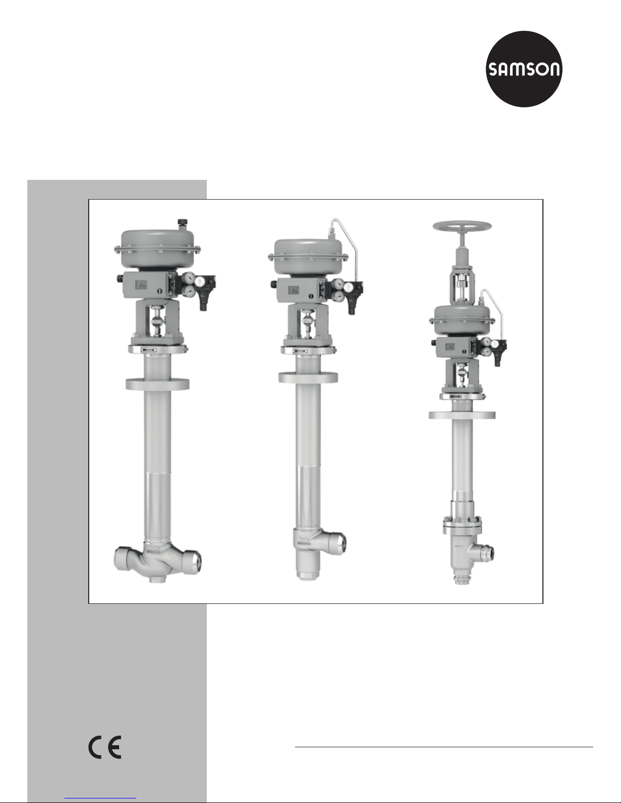
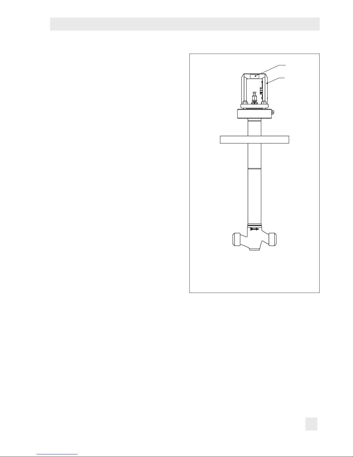
Type 3248 Valve
In combination with an actuator,
e.g. a SAMSON Type3271 or Type3277 Pneumatic Actuator
DIN version
Page 2
2 EB 8093 EN
Note on these mounting and operating instructions
These mounting and operating instructions assist you in mounting and operating the device
safely. The instructions are binding for handling SAMSON devices.
Î For the safe and proper use of these instructions, read them carefully and keep them for
later reference.
Î If you have any questions about these instructions, contact SAMSON‘s After-sales Service
Department (aftersalesservice@samson.de).
The mounting and operating instructions for the devices are included in
the scope of delivery. The latest documentation is available on our website
(www.samson.de) > Product documentation. You can enter the document
number or type number in the [Find:] eld to look for a document.
Denition of signal words
Hazardous situations which, if not avoided,
will result in death or serious injury
Hazardous situations which, if not avoided,
could result in death or serious injury
Property damage message or malfunction
Additional information
Recommended action
DANGER
!
WARNING
!
NOTICE
!
Note
Tip
Page 3

Contents
EB 8093 EN 3
1 Safety instructions and measures ...................................................................5
1.1 Notes on possible severe personal injury .........................................................8
1.2 Notes on possible personal injury ...................................................................9
1.3 Notes on possible property damage ..............................................................10
2 Markings on the control valve ......................................................................12
2.1 Valve nameplate ..........................................................................................12
2.2 Actuator nameplate ......................................................................................13
2.3 Material number ..........................................................................................13
3 Design and principle of operation ................................................................14
3.1 Fail-safe positions ........................................................................................17
3.2 Versions ......................................................................................................17
3.3 Technical data .............................................................................................18
4 Measures for preparation ............................................................................24
4.1 Unpacking ..................................................................................................24
4.2 Transporting and lifting ................................................................................24
4.2.1 Transporting ................................................................................................25
4.2.2 Lifting ..........................................................................................................26
4.3 Storage .......................................................................................................30
4.4 Preparation for installation ............................................................................31
5 Mounting and start-up ................................................................................. 32
5.1 Installing the valve into the pipeline ...............................................................32
5.1.1 Checking the installation conditions ...............................................................32
5.1.2 Additional ttings .........................................................................................34
5.1.3 Installing the control valve .............................................................................34
5.2 Removing the protective cover .......................................................................35
5.3 Mounting the actuator onto the valve .............................................................37
5.4 Quick check ................................................................................................38
6 Operation ...................................................................................................40
6.1 Working in manual mode ............................................................................. 40
Page 4

4 EB 8093 EN
Contents
7 Servicing.....................................................................................................42
7.1 Replacing the gasket ....................................................................................43
7.1.1 Globe or angle valve, PN16 to 40 ...............................................................43
7.1.2 Globe or angle valve, PN63 and 100...........................................................44
7.2 Replacing the packing ..................................................................................45
7.2.1 Globe or angle valve, PN16 to 40 ...............................................................45
7.2.2 Globe or angle valve, PN63 and 100...........................................................46
7.3 Replacing the seat and plug ..........................................................................47
7.4 Replacing the bellows seal ............................................................................47
7.5 Preparation for return shipment ..................................................................... 47
7.6 Ordering spare parts and operating supplies .................................................47
8 Malfunctions ...............................................................................................48
8.1 Troubleshooting ...........................................................................................48
8.2 Emergency action ........................................................................................49
9 Decommissioning and disassembly ..............................................................50
9.1 Decommissioning .........................................................................................50
9.2 Removing the valve from the pipeline .............................................................50
9.3 Removing the actuator from the valve ............................................................50
9.4 Disposal ......................................................................................................50
10 Appendix ....................................................................................................52
10.1 After-sales service ........................................................................................52
10.2 Certicates ..................................................................................................52
10.3 Spare parts .................................................................................................55
Page 5

EB 8093 EN 5
Safety instructions and measures
1 Safety instructions and measures
Intended use
The SAMSON Type3248 Globe and Angle Valve in combination with an actuator (e.g.
Type3271 or Type3277 Pneumatic Actuator) is designed to regulate the ow rate, pressure
or temperature of liquids or gases in cryogenic applications. For this purpose, the valves can
be welded into vacuum-insulated pipelines or cold boxes. The valve with its actuator is designed to operate under exactly dened conditions (e.g. operating pressure, process medium, temperature). Therefore, operators must ensure that the control valve is only used in ap-
plications that meet the specications used for sizing the valve at the ordering stage. In case
operators intend to use the control valve in other applications or conditions than specied,
SAMSON must be contacted.
SAMSON does not assume any liability for damage resulting from the failure to use the
valve for its intended purpose or for damage caused by external forces or any other external
factors.
Î Refer to the technical data and nameplate for limits and elds of application as well as
possible uses.
Reasonably foreseeable misuse
The control valve is not suitable for the following applications:
− Use outside the limits dened during sizing and in the technical data
− Use outside the limits dened by the valve accessories mounted on the control valve
Furthermore, the following activities do not comply with the intended use:
− Use of non-original spare parts
− Performing service and repair work not described in these instructions
Qualications of operating personnel
The control valve must be mounted, started up, serviced, and repaired by fully trained and
qualied personnel only; the accepted industry codes and practices are to be observed.
According to these mounting and operating instructions, trained personnel refers to
individuals who are able to judge the work they are assigned to and recognize possible
hazards due to their specialized training, their knowledge and experience as well as their
knowledge of the applicable standards.
Page 6

6 EB 8093 EN
Safety instructions and measures
Personal protective equipment
We recommend wearing the following protective equipment depending on the process medium:
− Protective clothing, gloves, and eyewear in applications with cold or cryogenic and/or
corrosive media
− Wear hearing protection when working near the valve.
Î Check with the plant operator for details on further protective equipment.
Revisions and other modications
Revisions, conversions or other modications to the product are not authorized by SAMSON.
They are performed at the user's own risk and may lead to safety hazards, for example. Fur-
thermore, the product may no longer meet the requirements for its intended use.
Safety feature
Upon supply air or control signal failure, the valve moves to its fail-safe position (see section3.1). The fail-safe action of the actuator is the same as its direction of action and is specied on the nameplate of SAMSON actuators (see actuator documentation).
Warning against residual hazards
To avoid personal injury or property damage, plant operators and operating personnel must
prevent hazards that could be caused in the control valve by the process medium, the operat-
ing pressure, the signal pressure or by moving parts by taking appropriate precautions. They
must observe all hazard statements, warning and caution notes in these mounting and operating instructions, especially for installation, start-up, and service work.
Responsibilities of the operator
The operator is responsible for proper operation and compliance with the safety regulations.
Operators are obliged to provide these mounting and operating instructions as well as the
referenced documents to the operating personnel and to instruct them in proper operation.
Furthermore, the operator must ensure that operating personnel or third persons are not exposed to any danger.
Responsibilities of operating personnel
Operating personnel must read and understand these mounting and operating instructions as
well as the referenced documents and observe the hazard statements, warning and caution
notes specied in them. Furthermore, the operating personnel must be familiar with the ap-
plicable health, safety and accident prevention regulations and comply with them.
Page 7

EB 8093 EN 7
Safety instructions and measures
Referenced standards and regulations
The control valves comply with the requirements of the European Pressure Equipment Directive 2014/68/EU. Valves with a CE marking have a declaration of conformity, which in-
cludes information about the applied conformity assessment procedure. This declaration of
conformity is included in the Appendix of these instructions (see section10.2).
According to the ignition risk assessment performed in accordance with EN13463-1:2009,
section 5.2, the non-electrical control valves do not have their own potential ignition source
even in the rare incident of an operating fault. As a result, they do not fall within the scope of
Directive 2014/34/EU.
Î For connection to the equipotential bonding system, observe the requirements specied in
section 6.4 of EN60079-14 (VDE0165 Part 1).
Referenced documentation
The following documents apply in addition to these mounting and operating instructions:
− Mounting and operating instructions for mounted actuator, e.g. uEB8310-X for
Type3271 and Type3277 Actuators
− Mounting and operating instructions for mounted valve accessories (positioner, solenoid
valve etc.)
− uAB0100 for tools, tightening torques, and lubricant
− For oxygen service: Manual uH01
Page 8
8 EB 8093 EN
Safety instructions and measures
1.1 Notes on possible severe personal injury
DANGER
!
Risk of bursting in pressure equipment.
Control valves and pipelines are pressure equipment. Improper opening can lead to
valve components bursting.
Î Before starting any work on the control valve, depressurize all plant sections
concerned as well as the valve.
Î Drain the process medium from all the plant sections concerned as well as the
valve.
Î Wear personal protective equipment.
Risk of injury due to incorrect handling of oxygen or cryogenic gases.
The Type3248 Valve is frequently used for oxygen service or applications with cryogenic gases. Oxygen is a hazardous substance, which reacts quickly, leading to combustion or explosions. Contact with cryogenic gases causes severe frostbite and cold
burns (cryogenic burns). Operating personnel must be trained for these applications.
Unqualied operating personnel expose themselves and others to an increased risk of
injury.
Î Operating personnel must be sufciently trained and be made aware of the dan-
gers occurring in oxygen service and in applications with cryogenic gases.
Î Instructions and information on how to safely handle devices for oxygen service
can be found in the Manual uH01.
All SAMSON staff receives appropriate training before performing any activities in
connection with oxygen service. SAMSON's After-sales Service department also offers
such training courses for service staff to allow them to learn how to handle devices for
the above listed applications correctly and safely.
Tip
Page 9

EB 8093 EN 9
Safety instructions and measures
1.2 Notes on possible personal injury
WARNING
!
Crush hazard arising from moving parts.
The control valve contains moving parts (actuator and plug stems), which can injure
hands or ngers if inserted into the valve.
Î Do not insert hands or ngers into the yoke while the valve is in operation.
Î While working on the control valve, disconnect and lock the pneumatic air supply
as well as the control signal.
Risk of personal injury when the actuator vents.
While the valve is operating, the actuator may vent during closed-loop control or when
the valve opens or closes.
Î Install the control valve in such a way that the actuator does not vent at eye level.
Î Use suitable silencers and vent plugs.
Î Wear eye protection when working in close proximity to the control valve.
Risk of personal injury due to preloaded springs.
Valves in combination with pneumatic actuators with preloaded springs are under tension. These control valves with SAMSON pneumatic actuators can be identied by the
long bolts protruding from the bottom of the actuator.
Î Before starting any work on the actuator, relieve the compression from the preload-
ed springs (see associated actuator documentation).
Risk of personal injury due to residual process medium in the valve.
While working on the valve, residual process medium can escape and, depending on
its properties, may lead to personal injury, e.g. cold burns.
Î If possible, drain the process medium from all the plant sections concerned and the
valve.
Î Wear protective clothing, safety gloves, and eyewear.
Page 10

10 EB 8093 EN
Safety instructions and measures
WARNING
!
Risk of burn injuries due to cold components and pipelines.
Depending on the process medium, valve components and pipelines may get extremely
cold and cause cryogenic burns.
Î Allow components and pipelines to heat up.
Î Wear protective clothing and safety gloves.
1.3 Notes on possible property damage
NOTICE
!
Risk of valve damage due to contamination (e.g. solid particles) in the pipeline.
The plant operator is responsible for cleaning the pipelines in the plant.
Î Flush the pipelines before start-up.
Î Observe the maximum permissible pressure for valve and plant.
Risk of valve damage due to unsuitable medium properties.
The valve is designed for a process medium with dened properties.
Î Only use the process medium specied for sizing the valve.
Risk of leakage and valve damage due to excessively high or low tightening torques.
Observe the specied torques on tightening control valve components. Excessively
tightened torques lead to parts wearing out quicker. Parts that are too loose may cause
leakage.
Î Observe the specied tightening torques (uAB0100).
Risk of valve damage due to the use of unsuitable tools.
Certain tools are required to work on the valve.
Î Only use tools approved by SAMSON (uAB0100).
Risk of valve damage due to the use of unsuitable lubricants.
The lubricants to be used depend on the valve material. Unsuitable lubricants may
corrode and damage the valve surface.
Î Only use lubricants approved by SAMSON (uAB0100).
Page 11

EB 8093 EN 11
Safety instructions and measures
Page 12
12 EB 8093 EN
Markings on the control valve
2 Markings on the control valve
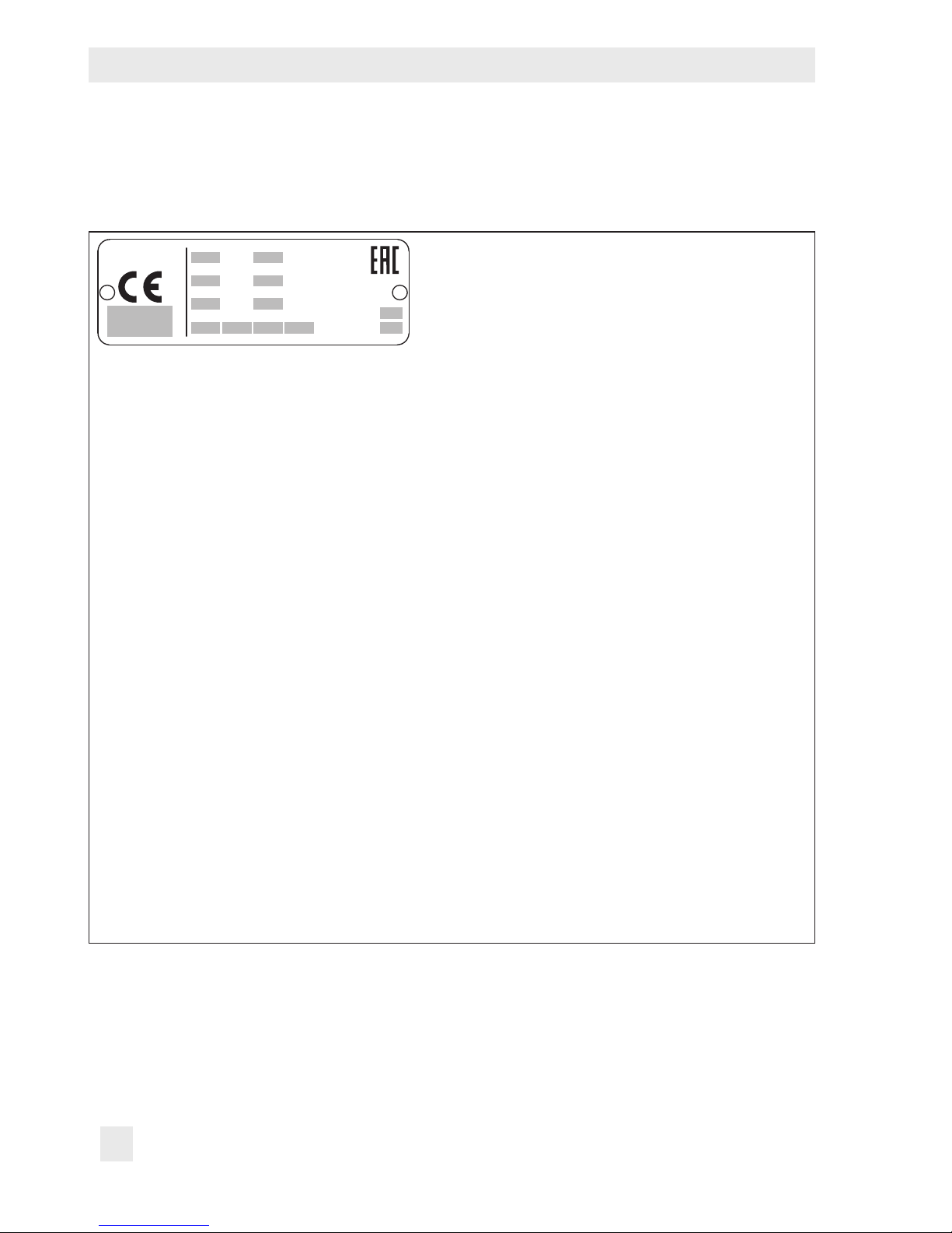
2.1 Valve nameplate
6 8
12 13
10 11
14
15
16
17
1…5
9
SAMSON
20
Fig.1: Valve nameplate
1…5 PED (Pressure Equipment Directive), "Art. 4, Abs. 3"
ID of the notied body, uid group, and category
6 Type designation
8 Material
9 Year of manufacture
10 Valve size:
DIN: DN · ANSI: NPS
11 Pressure rating:
DIN: PN · ANSI: CL
12 Order no. with modication index
For after-sales service orders: AA prex
13 Position in order
For after-sales service orders: conguration ID
14 Flow coefcient:
DIN: K
VS
· ANSI: C
V
15 Characteristic:
%: equal percentage · Lin: linear
16 Seat-plug seal:
ME: metal (see section3.3)
ST: Stellite
®
facing
PT: soft seal with PTFE
17 Seat code (trim material) · On request
20 Country of origin
Page 13
EB 8093 EN 13
Markings on the control valve
The nameplate is afxed to the valve bonnet
(see Fig.2).
2.2 Actuator nameplate
See associated actuator documentation.
2.3 Material number
The seat and plug of the valves have an article number written on them. Specifying this
article number, you can contact us to nd out
which material is used. Additionally, a seat
code is used to identify the trim material.
This seat code is specied on the nameplate
(17 on nameplate). For more details on the
nameplate, see section2.1.
2 Valve bonnet
80 Nameplate
80
2
Fig.2: Nameplate on the valve bonnet
Page 14

14 EB 8093 EN
Design and principle of operation
3 Design and principle of oper-
ation
The Type3248 is available in the following
versions:
− Globe valve with stainless steel body,
DN25 to 150, PN16 to 100 (see Fig.3)
− Angle valve with stainless steel body,
DN25 to 150, PN40 to 100 (see Fig.4)
− Angle valve with aluminum body, DN25
to 150, PN16 to 40 (see Fig.5)
A top-entry design is used for these valves.
As a result, the valve does not need to be removed from the pipeline for servicing work.
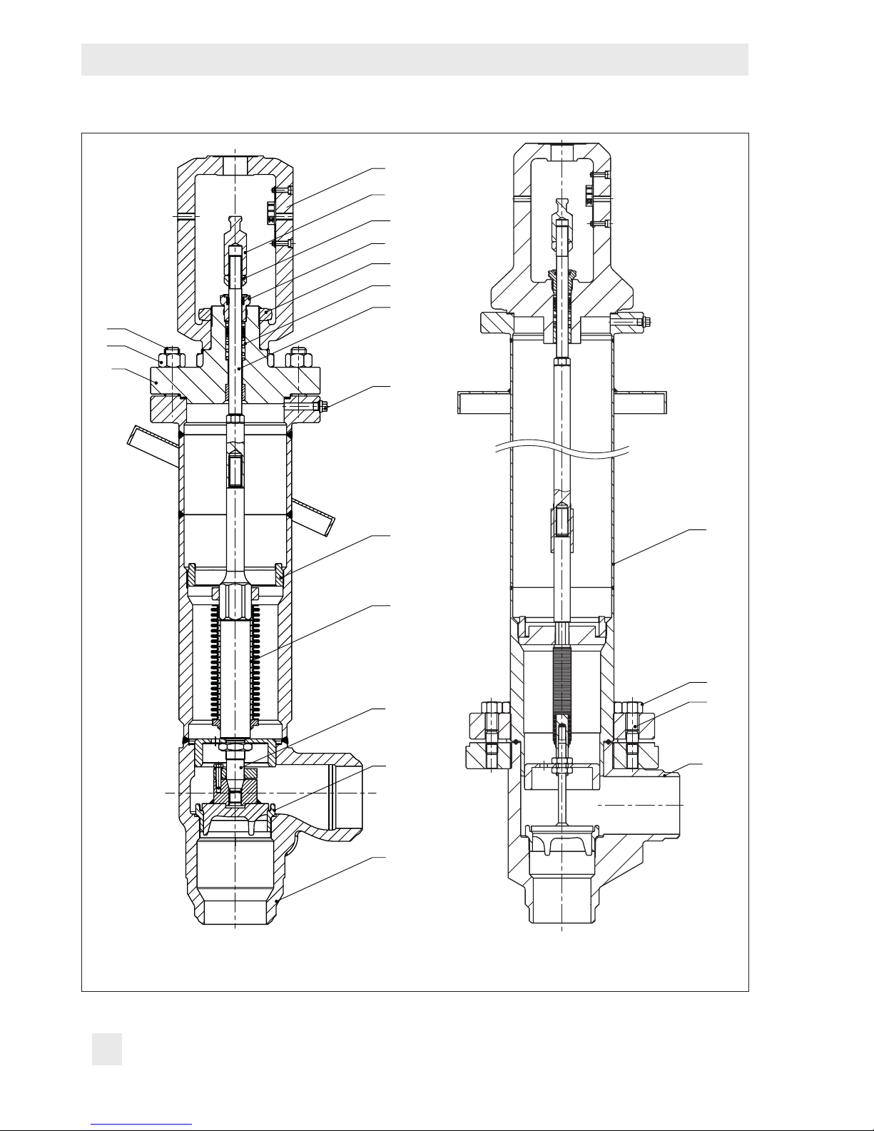
The seat (4) and plug with plug stem (5) are
installed in the body (1). The plug stem is
screwed to the plug stem with bellows seal
(37) which is, in turn, screwed to the spacer
stem (71). The stem connector clamps
(A26/27) connect the actuator stem (A7) of
the mounted actuator.
In the version with stainless steel body, the
cryogenic extension bonnet is welded onto
the body (1). Its bottom part consists of the
bellows seal and insulated pipe. In the version with aluminum body, the bellows seal
(22) is screwed to the body. A cover plate
can be welded at a specic angle onto the
pipe or bellows seal. The cover plate serves
as orientation during installation into a cold
box, for example.
The plug stem is sealed by the metal bellows
and the packing (15). The metal bellows prevents direct contact of the packing with the
process medium. As a result, the service life
is increased and icing up is prevented. The
test connection at the valve bonnet can be
used to monitor the sealing ability of the bellows. The packing consists of a spring-load-
ed PTFE-carbon V-ring packing.
In the PN16 to 40 version, the valve bonnet
(2) is designed as a yoke (see Fig.3). In the
PN63 and 100 version, the valve bonnet (2)
is designed as an intermediate piece. A yoke
(3) is fastened onto the valve bonnet with a
castellated nut (92) (see Fig.4).
A protective cover can be mounted in place
of the valve bonnet and actuator. This reduces the overall height of the valve and makes
it easier to transport it. The protective cover
also protects the inside of the bellows seal
against moisture and dirt.
The medium ows through the valve in the
direction indicated by the arrow. A rise in
signal pressure causes the force acting on
the diaphragm in the actuator to increase.
The springs are compressed. Depending on
the selected direction of action, the actuator
stem retracts or extends. As a result, the plug
position in the seat changes and determines
the ow rate through the valve.
Actuators
The Type3248 Valve is preferably combined
with a SAMSON Type3271 or Type3277
Pneumatic Actuator (see Fig.3). It can also
be combined with other actuators.
The springs in the pneumatic actuator are lo-
cated either above or below the diaphragm
depending on the selected fail-safe action
(see section3.1). A change in the signal
pressure acting on the diaphragm causes the
Page 15

EB 8093 EN 15
Design and principle of operation
Fig.3: Type3248 Globe Valve with
stainless steel body (PN16 to 40)
and with Type3271 Pneumatic
Actuator
Cover plate
1 Body (including cryogenic
extension bonnet)
2 Valve bonnet
4 Seat
5 Plug (with plug stem)
8 Threaded bushing (packing nut)
9 Stem connector nut
10 Lock nut
15 Packing
17 Bonnet gasket
37 Plug stem with metal bellows
41 Bellows nut
42 Test connection
71 Spacer stem
A7 Actuator stem
A26/27 Stem connector clamps
1
4
5
37
41
71
42
15
8
2
17
9
A7
A26/27
10
Page 16
16 EB 8093 EN
Design and principle of operation
1
4
5
37
41
42
33
15
8
10
9
71
92
32
2
3
22
14
13
1
Fig.4: Type3248 Angle Valve with stainless steel
body (PN100)
Fig.5: Type3248 Angle Valve with aluminum
body (PN16 to 40)
Page 17

EB 8093 EN 17
Design and principle of operation
plug to move. The actuator size is determined by the diaphragm area.
3.1 Fail-safe positions
The fail-safe position depends on the mounted actuator.
Depending on how the compression springs
are arranged in the pneumatic actuator, the
valve has two different fail-safe positions:
Actuator stem extends (FA)
When the signal pressure is reduced or the
air supply fails, the springs move the actuator stem downward and close the valve. The
valve opens when the signal pressure is increased enough to overcome the force exerted by the springs.
Actuator stem retracts (FE)
When the signal pressure is reduced or the
air supply fails, the springs move the actuator stem upwards and open the valve. The
valve closes when the signal pressure is increased enough to overcome the force exerted by the springs.
The actuator's direction of action can be reversed, if required. Refer to the mounting
and operating instructions of the pneumatic
actuator:
uEB8310‑X for Type3271 and Type3277
3.2 Versions
Larger nominal sizes
The Type3248 Valve is available up to nominal size DN200.
Actuators
In these instructions, the preferable combination with a Type3271 or Type3277 Pneumatic Actuator is described. The pneumatic
actuator (with or without handwheel) can be
replaced by another pneumatic actuator in a
different size, but with the same travel.
Î Observe the maximum permissible actu-
ator force.
Tip
1 Body
2 Valve bonnet
3 Yoke
4 Seat
5 Plug (with plug stem)
8 Threaded bushing (packing
nut)
9 Stem connector nut
10 Lock nut
13 Stud bolt
14 Body nut
15 Packing
17 Bonnet gasket
22 Bellows seal
32 Bolt
33 Nut
37 Plug stem with metal bellows
41 Bellows nut
42 Test connection
71 Spacer stem
92 Castellated nut
Page 18
18 EB 8093 EN
Design and principle of operation
If the travel range of the actuator is larger
than the travel range of the valve, the spring
assembly in the actuator must be preloaded
so that the travel ranges match. See associated actuator documentation.
The basic pneumatic actuator can be replaced by a pneumatic actuator with additional handwheel.
3.3 Technical data
The nameplates on the valve and actuator
provide information on the control valve
version. See section2.1 and the actuator
documentation.
More information is available in Data Sheet
uT8093.
Compliance
The Type3248 Valve bears both the CE and
EAC marks of conformity.
Temperature range
The Type3248 Valve is designed for a
temperature range from –196 to +65°C.
The use of an extended bellows seal extends
the temperature range down to –273°C.
Leakage class
Depending on the version, the following
leakage class according to IEC60534-4
applies:
Seal (16 on nameplate) Leakage class
Metal seal (ME) IV
High-performance metal
seal, e.g. Stellite® facing
(ST)
V
PTFE soft seal (PT) VI
Noise emission
SAMSON is unable to make general
statements about noise emission as it
depends on the valve version, plant facilities,
and process medium. On request, SAMSON
can perform calculations according to
IEC60534, Part8-3 and Part8-4 or
VDMA24422 (edition 89).
Risk of hearing loss or deafness due to loud
noise.
Wear hearing protection when working near
the valve.
Dimensions and weights
Table1 to Table5 provide a summary of the
dimensions of the various versions of
Type3248 Valve. Table6 lists the weights of
the various versions of Type3248 Valve. The
lengths and heights in the dimension dia-
grams are shown on page22.
Note
Note
WARNING
!
Page 19

EB 8093 EN 19
Design and principle of operation
Height H7 is the minimum clearance for service work. The actuator dimensions must also
be observed. The largest value applies.
Height H1 and the specied weights are reference values. The exact dimensions and
weights depend on various factors, e.g. actuator size and overall height.
Note
Table1: Dimensions of globe valve with stainless steel body, PN16 to 40
Valve DN 25 40 50 80 100 150
L mm 210 251 286 337 394 508
H1 mm 854 864 864 1052 1147.5 1188.5
H2 mm 44 71 71 93 111 174
H4 mm 600 600 600 700 800 800
H5 mm 708 714 714 824 933.5 974.5
H7 mm 1050 900 900 900 1100 1100
Ød mm 282 282 282 282 282 282
Welding ends/
pipe connection
1)
Ø33.7
x 2.3
Ø48.3
x2.6
Ø60.3
x 3.2
Ø88.9
x 4
Ø114.3
x 5
Ø168.3
x 5.6
1)
Deviating dimensions on request
Page 20

20 EB 8093 EN
Design and principle of operation
Table2: Dimensions of globe valve with stainless steel body, PN63 and 100
Valve DN 25 40 50 80 100 150
L mm 210 251 286 337 394 508
H1
1)
mm 822 817 817 832 984 1298
H2 mm 44 71 71 93 111 174
H4
2)
mm 600 600 600 600 650 800
H5 mm 734 734 734 734 786 923
H7 mm 1050 900 900 900 1100 1100
Ød mm 282 282 282 282 282 282
Welding ends/
pipe connection
2)
Ø33.7
x 3.2
Ø48.3
x 3.6
Ø60.3
x 4
Ø88.9
x 5.6
Ø114.3
x 6.3
Ø168.3
x 7.1
1)
Dimension H1+85mm applies when 1400-120cm² actuators are used
2)
Deviating dimensions on request
Table3: Dimensions of angle valve with stainless steel body, PN40
Valve DN 25 40 50 80 100 150
L mm 98 133 133 159 184 236
H1 mm 830 845 845 1017 1108 1101
H4 mm 600 600 600 650 750 750
H5 mm 684 695 695 788 893 887
H7 mm 1050 900 900 900 1100 1100
Ød mm 282 282 282 282 282 282
Welding ends/
pipe connection
Ø33.7
x 2.3
Ø48.3
x 2.6
Ø60.3
x 3.2
Ø88.9
x 4
Ø114.3
x 5
Ø168.3
x 5.6
Page 21

EB 8093 EN 21
Design and principle of operation
Table4: Dimensions of angle valve with stainless steel body, PN100
Valve DN 25 40 50 80 100 150
L mm 98 133 133 159 184 236
H1
1)
mm 798 798 798 795.5 943 1210
H4
2)
mm 400/600 400/600 400/600 400/600 500/600 550/600
H5
2)
mm 510/710 515/715 515/715 498/698 645/745 649/699
H7 mm 1050 900 900 900 1100 1100
Ød mm 282 282 282 282 282 282
Welding ends/
pipe connection
Ø33.7
x 3.2
Ø48.3
x3.6
Ø60.3
x 4
Ø88.9
x5.6
Ø114.3
x 6.3
Ø168.3
x 7.1
1)
Dimension H1+85mm applies when 1400-120cm² actuators are used
2)
Different overall height possible
Table5: Dimensions of angle valve in stainless steel version with aluminum body, PN16 to
40
1)
Valve DN 25 40 50 80 100 150
L mm
98 133 133 159 184 236
H1 mm 825 827 827 1035 1120 1149
H4 mm 600 600 600 700 800 800
H5 mm 679 677 677 807 906 935
H7 mm 1050 900 900 900 1100 1100
Ød mm 282 282 282 282 282 282
Welding ends/
pipe connection
Ø35
x 3.5
Ø50
x4
Ø60
x4
Ø89
x5
Ø114
x6
Ø162
x8
1)
Higher nominal pressures on request
Page 22

22 EB 8093 EN
Design and principle of operation
Dimensional drawings
H7
h=30
H2 H1
Ød
L
t=3
t=3
H4
H5
t=3
t=3
L
H4
H5
H1
h=30
Ød
L
H7
Globe valve with stainless steel body Angle valve with stainless steel body
H7
t=3
t=3
H4
H5
Ød
h=30
H1
L
L
Angle valve with aluminum body
Page 23

EB 8093 EN 23
Design and principle of operation
Table6: Weights of Type3248 Valve · Without actuator
Valve DN 25 40 50 80 100 150
Globe valve with stainless steel body, PN16 to 40
Weight kg 16 26 26 55 96 148
Globe valve with stainless steel body, PN63 and 100
Weight kg 17 30 30 59 106 186
Angle valve with stainless steel body, PN40
Weight kg 16.5 27 27 57 98 127
Angle valve with stainless steel body, PN100
Weight kg 18 31 31 61 107 186
Angle valve in stainless steel version with aluminum body, PN16 to 40
Weight kg 18 37 37 68 107 130.5
Refer to the following data sheets for dimensions and weights of the SAMSON pneumatic
actuators:
uT8310‑1 for Type3271 and Type3277 Actuators up to 750cm² actuator area
uT8310‑2 for Type3271 Actuator with 1000cm² actuator area and larger
uT8310‑3 for Type3271 Actuator with 1400‑60cm² actuator area
Note
Page 24

24 EB 8093 EN
Measures for preparation
4 Measures for preparation
After receiving the shipment, proceed as follows:
1. Check the scope of delivery. Compare
the shipment received against the delivery note.
2. Check the shipment for transportation
damage. Report any damage to
SAMSON and the forwarding agent (refer to delivery note).
4.1 Unpacking
Do not remove the packaging until immediately before installing the valve into the pipeline.
Proceed as follows to lift and install the
valve:
1. Remove the packaging from the valve.
2. Dispose of the packaging in accordance
with the valid regulations.
Risk of valve damage due to foreign particles entering the valve.
The protective caps tted on the valve's inlet
and outlet prevent foreign particles from entering the valve and damaging it.
Do not remove the protective caps until immediately before installing the valve into the
pipeline.
4.2 Transporting and lifting
Hazard due to suspended loads falling.
Stay clear of suspended or moving loads.
Risk of lifting equipment tipping and risk of
damage to lifting accessories due to exceeding the rated lifting capacity.
− Only use approved lifting equipment and
accessories whose minimum lifting capacity is higher than the weight of the valve
(including actuator, if applicable).
− Refer to section3.3 and the corresponding
data sheets for the weights.
Risk of personal injury due to control valve
tipping.
− Observe the valve's center of gravity.
− Secure the valve against tipping over or
turning.
Note
NOTICE
!
DANGER
!
WARNING
!
WARNING
!
Page 25

EB 8093 EN 25
Measures for preparation
Risk of valve damage due to incorrectly attached slings.
The welded-on lifting eyelet on SAMSON
actuators is only intended for mounting and
removing the actuator as well as lifting the
actuator without valve. Do not use this lifting
eyelet to lift the entire control valve assembly.
− When lifting the control valve, make sure
that the slings attached to the valve body
bear the entire load.
− Do not attach load-bearing slings to the
actuator, handwheel or any other parts.
− Observe lifting instructions (see sec-
tion4.2.2).
SAMSON's After-sales Service department
can provide more detailed transport and lifting instructions on request.
4.2.1 Transporting
The control valve can be transported using
lifting equipment (e.g. crane or forklift).
Î Leave the control valve in its transport
container or on the pallet to transport it.
Î Observe the transport instructions.
Transport instructions
− Protect the control valve against external
inuences (e.g. impact).
− Do not damage the corrosion protection
(paint, surface coatings). Repair any
damage immediately.
− Protect the control valve against moisture
and dirt.
− The permissible transportation tempera-
ture of standard control valves is –20 to
+65°C.
Contact SAMSON's After-sales Service department for the transportation temperatures
of other valve versions.
NOTICE
!
Tip
Note
Page 26

26 EB 8093 EN
Measures for preparation
Fig.6: Lifting using one hook
4.2.2 Lifting
To install a large valve into the pipeline, use
lifting equipment (e.g. crane or forklift) to lift
it.
Lifting instructions
− Secure slings against slipping.
− Make sure the slings can be removed
from the valve once it has been installed
into the pipeline.
− Prevent the control valve from tilting or
tipping.
− Do not leave loads suspended when in-
terrupting work for longer periods of
time.
− We recommend using a hook with safety
latch (see Fig.9). The safety latch prevents
the slings from slipping during lifting and
transporting.
− Angle valves with aluminum bodies have
threaded holes in the body in which swivel
lifting hooks can be screwed for lifting the
control valve.
Tip
Page 27

EB 8093 EN 27
Measures for preparation
Lifting with the actuator mounted
The control valve can be lifted in the hori-
zontal position either using one hook (Fig.6)
or using several hooks on a beam (Fig.7).
1. Attach one sling to the valve body, cryo-
genic extension bonnet, and valve bonnet or yoke as well as to the rigging
equipment (e.g. hook) of the crane or
forklift (see Fig.6).
2. With beam, DN100 and larger: attach
additional sling to support the valve at
the body.
3. Carefully lift the control valve. Check
whether the lifting equipment and accessories can bear the weight.
4. Move the control valve at an even pace
to the site of installation.
5. Install the valve into the pipeline (see sec-
tion5.1.3).
6. After installation in the pipeline, check
whether the weld seams hold.
7. Remove slings.
Fig.7: Lifting using a beam
Page 28

28 EB 8093 EN
Measures for preparation
Lifting with the protective cover mounted
1. Attach two slings to the cryogenic extension bonnet and to the rigging equipment (e.g. hook) of the crane or forklift
(see Fig.8).
2. DN100 and larger: attach additional
sling to support the valve at the body.
3. Proceed as described in Lifting with the
actuator mounted, steps3 to 7.
Lifting the control valve with mounted actuator in the upright position
Optionally, the valve can be lifted in the up-
right position (see Fig.9).
On lifting the control valve in the upright position, make sure the following conditions
are met:
− Make sure that the axis of the pipeline is
always horizontal during lifting and the
axis of the plug stem is always vertical.
− Make sure that the additional sling be-
tween the lifting eyelet and rigging
equipment (hook, shackle etc.) does not
bear any load when lifting actuators with
an actuator area of 700cm² or larger.
The sling only protects the control valve
from tilting while being lifted. Before lifting the control valve, tighten the sling.
Fig.8: Lifting using a beam when the protective cover is mounted
Page 29

EB 8093 EN 29
Measures for preparation
Fig.9: Lifting points on the control valve: globe valve (left) and angle valve (right)
Page 30

30 EB 8093 EN
Measures for preparation
For lifting in the upright position, proceed as
follows:
1. Attach one sling to each welding end of
the body and to the rigging equipment
(e.g. hook) of the crane or forklift (see
Fig.9).
2. Secure the slings attached to the body
against slipping using a connector.
3. 700cm² and larger: attach another
sling to the lifting eyelet on the actuator
and to the rigging equipment.
4. Carefully lift the control valve. Check
whether the lifting equipment and accessories can bear the weight.
5. Move the control valve at an even pace
to the site of installation.
6. Install the valve into the pipeline (see sec-
tion5.1.3).
7. After installation in the pipeline, check
whether the weld seams hold.
8. Remove connector and slings.
4.3 Storage
Risk of valve damage due to improper storage.
− Observe storage instructions.
− Avoid long storage times.
− Contact SAMSON in case of different stor-
age conditions or long storage periods.
We recommend regularly checking the control valve and the prevailing storage conditions during long storage periods.
Storage instructions
− Protect the control valve against external
inuences (e.g. impact).
− Do not damage the corrosion protection
(paint, surface coatings). Repair any
damage immediately.
− Protect the control valve against moisture
and dirt. Store it at a relative humidity of
less than 75%. In damp spaces, prevent
condensation. If necessary, use a drying
agent or heating.
− Make sure that the ambient air is free of
acids or other corrosive media.
− The permissible storage temperature of
standard control valves is –20 to +65°C.
NOTICE
!
Note
Page 31

EB 8093 EN 31
Measures for preparation
Contact SAMSON's After-sales Service department for the storage temperatures of other valve versions.
− Do not place any objects on the control
valve.
Special storage instructions for elastomers
Elastomer, e.g. actuator diaphragm
− To keep elastomers in shape and to pre-
vent cracking, do not bend them or hang
them up.
− We recommend a storage temperature of
15°C for elastomers.
− Store elastomers away from lubricants,
chemicals, solutions, and fuels.
SAMSON's After-sales Service department
can provide more detailed storage instructions on request.
4.4 Preparation for installation
Proceed as follows:
Î Flush the pipelines.
The plant operator is responsible for cleaning the pipelines in the plant.
Î Check the valve to make sure it is clean.
Î Check the valve for damage.
Î Check to make sure that the type desig-
nation, valve size, material, pressure rating, and temperature range of the valve
match the plant conditions (size and
pressure rating of the pipeline, medium
temperature etc.).
Î Check any mounted pressure gauges to
make sure they function.
Î When the valve and actuator are al-
ready assembled, check the tightening
torques of the bolted joints (uAB0100).
Components may loosen during trans-
port.
Note
Tip
Note
Page 32

32 EB 8093 EN
Mounting and start-up
5 Mounting and start-up
SAMSON valves are delivered ready for
use. In some cases, the valve is delivered
with a protective cover mounted. This can be
removed either before or after the valve is in-
stalled into the pipeline (see section5.2). The
procedure to mount and start up the valve
are described in following.
Risk of valve damage due to excessively high
or low tightening torques.
Observe the specied torques on tightening
control valve components. Excessively tight-
ened torques lead to parts wearing out
quicker. Parts that are too loose may cause
leakage.
Observe the specied tightening torques
(uAB0100).
Risk of valve damage due to the use of unsuitable tools.
Only use tools approved by SAMSON
(uAB0100).
5.1 Installing the valve into the
pipeline
5.1.1 Checking the installation
conditions
Pipeline routing
The inlet and outlet lengths vary depending
on the process medium. To ensure the control
valve functions properly, follow the installation instructions given below:
Î Observe the inlet and outlet lengths (see
Table7). Contact SAMSON if the valve
conditions or state of the medium process
deviate.
Î Install the valve free of stress and with the
least amount of vibrations as possible. If
necessary, attach supports to the valve.
Î Install the valve allowing sufcient space
to remove the actuator and valve or to
perform service and repair work on
them.
Mounting position
We recommend mounting the valve at an
angle between 15 and 25° to the horizontal
plane.
Î Contact SAMSON if the mounting posi-
tion is not as specied above.
Support or suspension
Depending on the valve version and mounting position, the control valve and pipeline
must be supported or suspended. The plant
engineering company is responsible in this
case.
NOTICE
!
NOTICE
!
Page 33

EB 8093 EN 33
Mounting and start-up
Table7: Inlet and outlet lengths
Q
a x DN b x DN
State of process
medium
Valve conditions Inlet length a Outlet length b
Gas
Ma≤0.3 2 4
0.3≤Ma≤0.7 2 10
Liquid
Free of cavitation/w<10m/s 2 4
Cavitation producing noise/w≤3m/s 2 4
Cavitation producing noise/3<w<5m/s 2 10
Critical cavitation/w≤3m/s 2 10
Critical cavitation/3<w<5m/s 2 20
Flashing – 2 20
Q Flow rate
a Inlet length
b Outlet length
Premature wear and leakage due to insufcient support or suspension.
In the following versions, the control valve
must be supported or suspended:
− For versions with side-mounted handwheel
which are installed at an angle of <45° to
the horizontal plane
Attach a suitable support or suspension to
the valve.
Î Avoid supporting or suspending the
valve in the area around bellows nut
(41).
Vent plugs
Vent plugs are screwed into the exhaust air
ports of pneumatic devices. They ensure that
any exhaust air that forms can be vented to
the atmosphere (to avoid excess pressure in
the device). Furthermore, the vent plugs allow air intake to prevent a vacuum from
forming in the device.
Î Locate the vent plug on the opposite side
to the workplace of operating personnel.
Î On mounting valve accessories, make
sure that they can be operated from the
workplace of the operating personnel.
NOTICE
!
Page 34

34 EB 8093 EN
Mounting and start-up
The workplace of operating personnel is the
location from which the valve, actuator, and
any mounted valve accessories can be accessed to operate them.
5.1.2 Additional ttings
Insulation
Control valves with cover plates can be insulated up to the cover plate. Control valves
without cover plates must only be insulated
up to the top of the body ange.
Safety guard
To reduce the crush hazard arising from
moving parts (actuator and plug stem), a
safety guard can be installed.
Test connection
The test connection at the valve bonnet can
be used to monitor the sealing ability of the
bellows. Particularly for liquids and vapors,
we recommend installing a suitable leakage
indicator (e.g. a contact pressure gauge, an
outlet to an open vessel or an inspection
glass).
5.1.3 Installing the control
valve
1. Close the shut-off valve in the pipeline
while the valve is being installed.
2. Remove the protective caps from the
valve ports before installing the valve.
3. Lift the valve using suitable lifting equipment to the site of installation (see sec-
tion4.2.2). Observe the ow direction
through the valve. The arrow on the
valve indicates the direction of ow.
4. Completely retract the actuator stem to
protect the plug from sparks during welding:
With mounted protective cover: turn the
adjustment bolt (95.2) clockwise.
With mounted actuator, "stem extends"
direction of action: apply a signal pressure to the actuator.
With mounted actuator, "stem retracts"
direction of action: the valve is open
without any signal pressure being applied.
5. Weld the valve free of stress into the
pipeline.
6. Depending on the eld of application,
allow the valve to cool down or heat up
to reach ambient temperature before
start up.
7. Slowly open the shut-off valve in the
pipeline after the valve has been installed.
Risk of valve damage due to a sudden pressure increase and resulting high ow velocities.
Slowly open the shut-off valve in the pipeline
during start-up.
8. Check the valve to ensure it functions
properly. See section5.4.
Note
NOTICE
!
Page 35

EB 8093 EN 35
Mounting and start-up
5.2 Removing the protective
cover
To keep the overall height of valves for coldbox applications during transportation, the
actuator and valve body can be removed
from the body (cryogenic extension bonnet).
In this case, the plug stem with bellows seal
(37) is secured by a protective cover. The
valve can be installed into the pipeline with
the protective cover still mounted. The protective cover can remain mounted on the valve
also during a pressure test (see section5.4).
Upon delivery with the protective cover, the
valve is open: the thread of the plug stem
with bellows seal (37) is completely screwed
into the adjustment bolt (95.2).
Moving the plug stem
Î To close the valve, turn the adjustment
bolt (95.2) counterclockwise.
Î To open the valve, turn the adjustment
bolt (95.2) clockwise.
A plate on the protective cover indicates the
turning direction (see Fig.10).
Removing the protective cover
1. Remove nuts (33) and washers (95.9).
2. Turn the adjustment bolt (95.2) counter-
clockwise. The plug is lowered and the
protective cover is lifted off the body.
3. As soon as the end of the thread is
reached, remove the protective cover
from the body.
The nuts (33) are required to mount the valve
bonnet. The washers (95.9) are no longer
required.
Mounting the valve bonnet
For PN63 and 100 versions, mount the
valve bonnet (2) together with the yoke (3).
1. Insert a new gasket (17) into the body
(1).
2. Carefully place the valve bonnet (2) together with the spacer stem (71) on the
valve body (1). Place the spacer stem
over the thread of the plug stem (37) and
tighten by hand. Make sure that the position of the stem connector nut (9) and
Tip
Note
Note
Fig.10: Plate indicating the
turning direction of the
adjustment bolt
Page 36

36 EB 8093 EN
Mounting and start-up
33
9
10
3
2
71
37
17
1
32
8
92
F
M
A
42
43
95.2
95.3
95.4
95.9
95.1
37
95.5
95.6
95.7
33
32
1 Body
2 Valve bonnet
3 Yo ke
9 Stem connector nut
10 Lock nut
17 Bonnet gasket
32 Bolt
33 Nut
37 Plug stem with metal
bellows
42 Screw plug (test
connection)
43 Gasket
71 Spacer stem
95.1 Cover of protective cover
95.2 Stud/adjustment bolt
95.3 Axial retaining ring
95.4 O-ring
95.5 Gasket
95.6 Screw plug (test
connection)
95.7 O-ring (glued)
95.9 Washer (spacer sleeve)
9
10
2
71
37
17
1
8
PN16 to 40
PN63 and 100
Fig.11: Protective cover and valve bonnet
Page 37

EB 8093 EN 37
Mounting and start-up
lock nut (10) on the spacer stem is not
changed.
3. Fasten the valve bonnet (2) using the nuts
(33) and bolts (32). Tighten the nuts
gradually in a criss-cross pattern. Observe tightening torques.
4. Tighten the spacer stem (71) and plug
stem (37) over the stem connector nut
(9). Observe tightening torques.
5. Mount actuator. See associated actuator
documentation.
6. In case the position of the stem connector
nut and lock nut has been changed
during mounting (step2): adjust lower or
upper signal bench range. See associated actuator documentation.
5.3 Mounting the actuator onto
the valve
Proceed as described in the actuator documentation if the valve and actuator have not
been assembled by SAMSON.
If a protective cover is mounted, rst remove
it and mount the valve bonnet (see sec-
tion5.2).
Versions with V-port plug
Each V-port plug has three V-shaped ports.
Depending on the valve size, the size of the
symmetrically arranged V-shaped ports varies. The process medium in the valve ows
through the V-shaped ports as soon as the
plug is lifted out of the seat (i.e. the valve
opens).
1. Before mounting the actuator, determine
which V-shaped port is uncovered rst
when the plug is lifted out of the seat.
Usually, this is the largest V-shaped port.
2. On mounting the actuator, make sure
that the V-shaped port uncovered rst
faces toward the valve outlet.
Risk of damage to the wall of the valve body
due to incorrectly diverted jet stream.
The process medium cannot ow unobstructed through the valve when the V-port
plug has been installed incorrectly. This will
result in the process medium hitting the body
wall, which may lead to severe valve damage.
Make sure the V-port plug is installed
correctly.
− Remove the mounted actuator before
mounting the other actuator (see associat-
ed actuator documentation).
− Preloading the actuator springs increases
the thrust of a pneumatic actuator and reduces the travel range of the actuator (see
associated actuator documentation).
Tip
NOTICE
!
Information
Page 38

38 EB 8093 EN
Mounting and start-up
5.4 Quick check
SAMSON valves are delivered ready for
use. To test the valve's ability to function, the
following quick checks can be performed:
Tight shut-off
1. Close the valve.
2. Slowly open the shut-off valve in the
pipeline.
Risk of valve damage due to a sudden pressure increase and resulting high ow velocities.
Slowly open the shut-off valve in the pipeline
during start-up.
3. Check the valve for leakage (visual inspection).
Travel motion
The movement of the actuator stem must be
linear and smooth.
Î Open and close the valve, observing the
movement of the actuator stem.
Î Apply the maximum and minimum con-
trol signals to check the end positions of
the valve.
Î Check the travel reading at the travel in-
dicator scale.
Fail-safe position
Î Shut off the signal pressure line.
Î Check whether the valve moves to the
fail-safe position.
Pressure test with mounted protective cover
With a mounted protective cover, perform
the test pressure with an open valve as well
as with a closed valve.
1. To open the valve, turn the adjustment
bolt (95.2) clockwise.
2. Perform the pressure test. Observe the
maximum permissible pressure for valve
and plant.
3. To close the valve, turn the adjustment
bolt (95.2) counterclockwise.
4. Perform the pressure test. Observe the
maximum permissible pressure for valve
and plant.
The plant operator is responsible for performing the pressure test. SAMSON's After-sales Service department can support you
to plan and perform a pressure test for your
plant.
Pressure test with mounted actuator
During the pressure test, make sure the following conditions are met:
− Retract the plug stem to open the valve.
− Observe the maximum permissible pres-
sure for valve and plant.
NOTICE
!
Note
Page 39

EB 8093 EN 39
Mounting and start-up
The plant operator is responsible for
performing the pressure test. SAMSON's
After-sales Service department can support
you to plan and perform a pressure test for
your plant.
Note
Page 40

40 EB 8093 EN
Operation
6 Operation
Immediately after completing mounting and
start-up (see section5), the valve is ready for
use.
Crush hazard arising from moving parts
(actuator and plug stem).
Do not insert hands or ngers into the yoke
while the valve is in operation.
Risk of personal injury when the actuator
vents.
Wear eye protection when working in close
proximity to the control valve.
Risk of burn injuries due to cold components
and pipelines.
Depending on the process medium, valve
components and pipelines may get extremely
cold and cause cryogenic burns.
Wear protective clothing and safety gloves.
Operation disturbed by a blocked actuator
or plug stem.
Do not impede the movement of the actuator
or plug stem by inserting objects into their
path.
6.1 Working in manual mode
Valves tted with actuators with a handwheel
can be manually closed or opened in case of
supply air failure.
Î For normal closed-loop operation, move
the handwheel to the neutral position.
WARNING
!
WARNING
!
WARNING
!
NOTICE
!
Page 41

EB 8093 EN 41
Page 42

42 EB 8093 EN
Servicing
7 Servicing
The control valve is subject to normal wear,
especially at the seat, plug, and packing.
Depending on the operating conditions,
check the valve at regular intervals to prevent possible failure before it can occur.
SAMSON's After-sales Service department
can support you to draw up an inspection
plan for your plant.
We recommend removing the valve from the
pipeline for service or repair work (see sec-
tion9.2).
Risk of bursting in pressure equipment.
Control valves and pipelines are pressure
equipment. Improper opening can lead to
bursting of the valve.
− Before starting any work on the control
valve, depressurize all plant sections concerned as well as the valve.
− Drain the process medium from all the
plant sections concerned as well as the
valve.
− Wear personal protective equipment.
Risk of personal injury due to residual process medium in the valve.
While working on the valve, residual process
medium can escape and, depending on its
properties, may lead to personal injury, e.g.
(chemical) burns.
Wear protective clothing, safety gloves, and
eyewear.
Risk of burn injuries due to cold components
and pipelines.
Depending on the process medium, valve
components and pipelines may get extremely
cold and cause cryogenic burns.
− Allow components and pipelines to cool
down or heat up.
− Wear protective clothing and safety gloves.
Risk of valve damage due to incorrect servicing or repair.
Service and repair work must only be performed by trained staff.
Risk of valve damage due to excessively high
or low tightening torques.
Observe the specied torques on tightening
control valve components. Excessively tight-
ened torques lead to parts wearing out
quicker. Parts that are too loose may cause
leakage.
Observe the specied tightening torques
(uAB0100).
Tip
DANGER
!
WARNING
!
WARNING
!
NOTICE
!
NOTICE
!
Page 43

EB 8093 EN 43
Servicing
Risk of valve damage due to the use of unsuitable tools.
Only use tools approved by SAMSON
(uAB0100).
Risk of valve damage due to the use of unsuitable lubricants.
Only use lubricants approved by SAMSON
(uAB0100).
The control valve was checked by SAMSON
before it left the factory.
− Certain test results (seat leakage and leak
test) certied by SAMSON lose their validity when the valve body or actuator housing is opened.
− The product warranty becomes void if ser-
vice or repair work not described in these
instructions is performed without prior
agreement by SAMSON's After-sales Service department.
− Only use original spare parts by
SAMSON, which comply with the original
specications.
7.1 Replacing the gasket
7.1.1 Globe or angle valve,
PN16 to 40
1. Remove the actuator from the valve. See
associated actuator documentation.
2. Undo the nuts (33) gradually in a crisscross pattern. Remove the nuts and bolts
(32).
3. Carefully lift the valve bonnet (2) off the
valve body (1) over the spacer stem (71).
4. Remove the gasket (17). Carefully clean
the sealing faces in the valve bonnet (2)
and on the body (1).
5. Insert a new gasket (17) into the body
(1).
6. Carefully place the valve bonnet (2) on
the valve body (1) over the spacer stem
(71).
7. Fasten the valve bonnet (2) using the nuts
(33) and bolts (32). Tighten the nuts
gradually in a criss-cross pattern. Observe tightening torques.
8. Mount actuator. See associated actuator
documentation.
9. Adjust lower or upper signal bench
range. See associated actuator documentation.
NOTICE
!
NOTICE
!
Note
Page 44

44 EB 8093 EN
Servicing
33
9
10
3
2
71
37
17
1
32
8
92
1 Body
2 Valve bonnet
3 Yoke
8 Threaded bushing
(packing nut)
9 Stem connector nut
10 Lock nut
17 Bonnet gasket
32 Bolt
33 Nut
37 Plug stem with metal
bellows
71 Spacer stem
92 Castellated nut
9
10
2
71
37
17
1
8
Fig.12: Valve bonnet: PN16 to 40 (left) · PN63 and 100 (right)
7.1.2 Globe or angle valve,
PN63 and 100
1. Remove the actuator from the valve. See
associated actuator documentation.
2. Unthread the stem connector nut (9) and
lock nut (10) from the spacer stem (71).
3. Loosen the threaded bushing (8) to re-
lieve the tension from the packing.
The threaded bushing does not need to be
completely unscrewed to replace the gasket.
4. Undo the nuts (33) gradually in a crisscross pattern. Remove the nuts and bolts
(32).
5. Carefully lift the valve bonnet (2) together with the yoke (3) off the valve body
(1) and the spacer stem (71).
6. Remove the gasket (17). Carefully clean
the sealing faces in the valve bonnet (2)
and on the body (1).
7. Insert a new gasket (17) into the body
(1).
Note
Page 45

EB 8093 EN 45
Servicing
8. Carefully place the valve bonnet (2) together with the yoke (3) on the valve
body (1) over the spacer stem (71).
9. Fasten the valve bonnet (2) using the nuts
(33) and bolts (32). Tighten the nuts
gradually in a criss-cross pattern. Observe tightening torques.
10. Tighten the threaded bushing (8). Observe tightening torques.
11. Loosely screw the lock nut (10) and stem
connector nut (9) onto the spacer stem
(71).
12. Mount actuator. See associated actuator
documentation.
13. Adjust lower or upper signal bench
range. See associated actuator documentation.
7.2 Replacing the packing
Risk of control valve damage due to incorrect
service or repair.
The packing can only be replaced when all
the following conditions are met:
− Nominal size of the valve is ≤DN150.
− The standard or FormD (for oxygen) pack-
ing is installed in the valve.
To replace the packing in other valve versions, contact SAMSON's After-sales Service
department.
7.2.1 Globe or angle valve,
PN16 to 40
1. Remove the actuator from the valve. See
associated actuator documentation.
2. Unthread the stem connector nut (9) and
lock nut (10) from the spacer stem (71).
3. Unscrew the threaded bushing (8).
4. Undo the nuts (33) gradually in a crisscross pattern. Remove the nuts and bolts
(32).
5. Carefully lift the valve bonnet (2) over the
spacer stem (71).
6. Pull all the packing parts out of the pack-
ing chamber using a suitable tool.
7. Renew the damaged parts and carefully
clean the packing chamber.
8. Replace gasket as described in sec-
tion7.1.1.
9. Apply a suitable lubricant to all the packing parts.
10. Carefully slide the packing parts over the
spacer stem (71) into the packing cham-
ber using a suitable tool. Observe the
proper sequence (see Fig.13).
11. Carefully place the valve bonnet (2) on
the valve body (1) over the spacer stem
(71).
12. Fasten the valve bonnet (2) using the nuts
(33) and bolts (32). Tighten the nuts
gradually in a criss-cross pattern. Observe tightening torques.
13. Screw in the threaded bushing (8) and
tighten it. Observe tightening torques.
NOTICE
!
Page 46

46 EB 8093 EN
Servicing
14. Loosely screw the lock nut (10) and stem
connector nut (9) onto the spacer stem
(71).
15. Mount actuator. See associated actuator
documentation.
16. Adjust lower or upper signal bench
range. See associated actuator documentation.
7.2.2 Globe or angle valve,
PN63 and 100
1. Remove the actuator from the valve. See
associated actuator documentation.
2. Unscrew the castellated nut (92) and lift
the yoke (3) off the valve bonnet (2).
3. Unthread the stem connector nut (9) and
lock nut (10) from the spacer stem (71).
4. Unscrew the threaded bushing (8).
5. Pull all the packing parts out of the pack-
ing chamber using a suitable tool.
6. Renew the damaged parts and carefully
clean the packing chamber.
7. Apply a suitable lubricant to all the packing parts.
8. Carefully slide the packing parts over the
spacer stem (71) into the packing chamber using a suitable tool. Observe the
proper sequence (see Fig.13).
9. Screw in the threaded bushing (8) and
tighten it. Observe tightening torques.
10. Place yoke (3) on the valve bonnet (2)
and fasten tight using the castellated nut
(92).
8
2
16
12
11
71
15
8
2
16
12
11
71
15
19
2 Valve bonnet
8 Threaded bushing
11 Spring
12 Washer
15 Packing
16 V-ring packing
19 Bushing
71 Spacer stem
Fig.13: Packing
Page 47

EB 8093 EN 47
Servicing
11. Loosely screw the lock nut (10) and stem
connector nut (9) onto the plug stem (5).
12. Mount actuator. See associated actuator
documentation.
13. Adjust lower or upper signal bench
range. See associated actuator documentation.
7.3 Replacing the seat and
plug
Risk of control valve damage due to incorrect
service or repair.
To replace seat and plug in the Type3248
Valve, contact SAMSON's After-sales Service department.
7.4 Replacing the bellows seal
Risk of control valve damage due to incorrect
service or repair.
To replace the bellows seal in the Type3248
Valve, contact SAMSON's After-sales Service department.
7.5 Preparation for return ship-
ment
Defective valves can be returned to
SAMSON for repair.
Proceed as follows to return valves to
SAMSON:
1. Put the control valve out of operation (see
section9).
2. Decontaminate the valve. Remove any
residual process medium.
3. Fill in the Declaration on Contamination,
which can be downloaded from our
website at uwww.samson.de > Services
> Check lists for after sales service >
Declaration on Contamination.
4. Send the valve together with the lled-in
form to your nearest SAMSON subsidiary. SAMSON subsidiaries are listed on
our website at uwww.samson.de >
Contact.
7.6 Ordering spare parts and
operating supplies
Contact your nearest SAMSON subsidiary
or the SAMSON After-sales Service department for information on spare parts, lubricants, and tools.
Spare parts
Details on spare parts are available on request.
Lubricant
Details on suitable lubricants can be found in
the document uAB0100.
Tools
Details on suitable tools can be found in the
document uAB0100.
NOTICE
!
NOTICE
!
Page 48

48 EB 8093 EN
Malfunctions
8 Malfunctions
Depending on the operating conditions, check the valve at certain intervals to prevent possible failure before it can occur. Operators are responsible for drawing up an inspection plan.
SAMSON's After-sales Service department can support you to draw up an inspection plan
for your plant.
8.1 Troubleshooting
Malfunction Possible reasons Recommended action
Actuator or plug stem does not
move on demand.
Actuator is blocked. Check attachment.
Unblock the actuator.
Signal pressure too low Check the signal pressure.
Check the signal pressure line for
leakage.
Actuator or plug stem does not
move through the whole range.
Signal pressure too low Check the signal pressure.
Check the signal pressure line for
leakage.
Increased ow through closed
valve (seat leakage)
Dirt or other foreign particles
deposited between the seat and
plug.
Shut off the section of the pipe-
line and ush the valve.
Valve trim, particularly with soft
seat, is worn.
Contact SAMSON's After-sales
Service department.
The valve leaks to the atmosphere (fugitive emissions).
The packing and metal bellows
are defective.
Contact SAMSON's After-sales
Service department.
Flange joint not tight. Check the ange joint.
Gasket worn out. Replace bonnet gasket. See
section7.1) or contact
SAMSON's After-sales Service
department.
Icing up of the packing chamber. Metal bellows is defective. Contact SAMSON's After-sales
Service department.
Tip
Page 49

EB 8093 EN 49
Malfunctions
Contact SAMSON's After-sales Service department for malfunctions not listed in the table.
Note
8.2 Emergency action
Upon supply air or control signal failure, the
valve moves to its fail-safe position (see sec-
tion3.1).
The plant operator is responsible for emergency action to be taken in the plant.
In the event of a valve malfunction:
1. Close the shut-off valves upstream and
downstream of the control valve to stop
the process medium from owing
through the valve.
2. Check the valve for damage. If necessary, contact SAMSON's After-sales Service department.
Putting the valve back into operation after
a malfunction
Î Slowly open the shut-off valves. Allow
the process medium to slowly ow into
the valve.
Page 50

50 EB 8093 EN
Decommissioning and disassembly
9 Decommissioning and disas-
sembly
Risk of bursting in pressure equipment.
Control valves and pipelines are pressure
equipment. Improper opening can lead to
bursting of the valve.
− Before starting any work on the control
valve, depressurize all plant sections concerned as well as the valve.
− Drain the process medium from all the
plant sections concerned as well as the
valve.
− Wear personal protective equipment.
Risk of personal injury due to residual process medium in the valve.
While working on the valve, residual process
medium can escape and, depending on its
properties, may lead to personal injury, e.g.
(chemical) burns.
Wear protective clothing, safety gloves, and
eyewear.
Risk of burn injuries due to cold components
and pipelines.
Depending on the process medium, valve
components and pipelines may get extremely
cold and cause cryogenic burns.
− Allow components and pipelines to cool
down or heat up.
− Wear protective clothing and safety gloves.
9.1 Decommissioning
To decommission the control valve for service
and repair work or disassembly, proceed as
follows:
1. Close the shut-off valves upstream and
downstream of the control valve to stop
the process medium from owing
through the valve.
2. Completely drain the pipelines and
valve.
3. Disconnect and lock the pneumatic air
supply to depressurize the actuator.
4. If necessary, allow the pipeline and valve
components to cool down or heat up.
9.2 Removing the valve from
the pipeline
1. Put the control valve out of operation (see
section9.1).
2. Cut the pipeline in front of the weld
seam.
3. Remove the valve from the pipeline (see
section4.2).
9.3 Removing the actuator
from the valve
See associated actuator documentation.
9.4 Disposal
Î Observe local, national, and internation-
al refuse regulations.
DANGER
!
WARNING
!
WARNING
!
Page 51

EB 8093 EN 51
Decommissioning and disassembly
Î Do not dispose of components, lubri-
cants, and hazardous substances together with your other household waste.
Page 52

52 EB 8093 EN
Appendix
10 Appendix
10.1 After-sales service
Contact SAMSON's After-sales Service department for support concerning service or
repair work or when malfunctions or defects
arise.
E-mail
You can reach the After-sales Service Department at aftersalesservice@samson.de.
Addresses of SAMSONAG and its subsidiaries
The addresses of SAMSON AG, its subsidiaries, representatives, and service facilities
worldwide can be found on the SAMSON
website, in all SAMSON product catalogs or
on the back of these Mounting and Operating Instructions.
Required specications
Please submit the following details:
− Order number and position number in
the order
− Type, model number, nominal size, and
valve version
− Pressure and temperature of the process
medium
− Flow rate in m³/h
− Bench range of the actuator (e.g. 0.2 to
1bar)
− Is a strainer installed?
− Installation drawing
10.2 Certicates
The declaration of conformity is provided on
the next page.
Page 53

EB 8093 EN 53
SAMSON AKTIENGESELLSCHAFT
Weismüllerstraße 3 60314 Frankfurt a m Main
Telefon: 069 4009-0 · Telefax: 069 400 9-1507
E-Mail: samson@sam son.de
Revison 01
ce_modul_h_de_en_rev01.d ocx
Modul/Module H / N° CE-PED-H-SAM 001-13-DEU
SAMSON erklärt in alleiniger Verantwortung für folgende Produkte/explaines in sole resposibility for the following products:
Geräte/Devices
Bauart/Series
Typ/ Type
Ausführung/Version
Durchgangsventil/Gl obe Valve 240 3241
DIN, Gehäuse GG/Ca st iron-Body ab/fr om DN150, Gehäuse GGG /Sph. gr.
iron-Body ab/from DN 100, Fluide/Fluids G 2, L1, L2
1)
DIN/ANSI, Geh. Stahl u.a./B ody Steel etc., alle Fluide/ all Fluids
Dreiwegeventil/Three -way Valve 240 3244
DIN, Gehäuse GG ab DN 150/Cast iron-Bod y from DN150; Gehäuse GG G ab
DN100/Sph. gr. iron-B ody from DN100, Fl uide/Fluids G2, L1, L2
1)
DIN/ANSI, Geh. Stahl u.a./B ody Steel etc., alle Fluide/ all Fluids
Tieftemperaturventi l/Cryogenic Valve 240 3248 DIN/ANSI, alle Fluide/all Fluids
Durchgangsventil/Gl obe Valve 250 3251 DIN/ANSI, alle Fluide/all Fluids
Dreiwegeventil/Three -way Valve 250 3253 DIN/ANS I, Geh. Stahl u.a./Bod y Steel etc., alle Fluide/ all Fluids
Durchgangsventil/Gl obe Valve 250 3254 DIN/ANSI, alle Fluide/all Fluids
Eckventil/Angle Valve 250 3256 DIN/ANSI, alle Fluide/all Fluids
Split-Body-Ventil/S plit-Body-Valve 250 3258 DIN, alle Fluide/all Fluids
IG-Eckventil/IG-Angl e Valve 250 3259 DIN, alle Fluide/all Fluids
Dampfumformventil/
Steam-converting Val ve
280
3281 DIN/ANSI, alle Fluide/all Fluids
3284 DIN/ANSI, alle Fluide/all Fluids
3286 DIN/ANSI, alle Fluide/all Fluids
3288 D IN, alle Fluide/all Fl uids
Durchgangsventile/G lobe Valve V200 1 3321
DIN, Geh. Stahl u.a./B ody Steel etc., all e Fluide/all Fluids
ANSI, alle Fluide/all Fluids
Dreiwegeventil/Three -way Valve V2001 3323
DIN, Geh. Stahl u.a./B ody Steel etc., all e Fluide/all Fluids
ANSI, alle Fluide/all Fluids
Schrägsitzventil/Bev el-Valve --- 3353 DIN, Geh. S tahl/Body Steel, all e Fluide/all Fluids
Drosselschalldämpfe r/Silencer 3381
3381-1
DIN/ANSI, alle Fluide/all Fluids; Einzeldrosselscheibe mit Anschweißende/
Single attenuation plate wit h welding end
3381-3 DIN/ANSI, alle Fluide/all Flui ds
3381-4
DIN/ANSI, alle Fluide/all Fluids; Einzeldrosselscheibe mehrstufig mit
Anschweißende/Single attenuation plat e multi-stage with weldi ng end
Durchgangsventil/Gl obe Valve 240 3241
ANSI, Gehäuse GG Cl 125 ab 5"/Cast iron-B ody Cl125 from 5", Fluide/Fluids
G2, L1, L2
1)
Tieftemperaturventi l/
Cryogenic Valve
240 3246 DIN /ANSI, alle Fluide/all Fluid s
Dreiwegeventil/Three -way Valve 250 3253
DIN, Gehäuse GG ab DN 200 PN16/Cast iron-B ody from DN200 PN 16,
Fluide/Fluids G2, L1, L2
1)
Durchgangsventil/Gl obe Valve 290 3291 ANSI, alle Fluide/all Flui ds
Eckventil/Angle Val ve 290 3296 ANSI, alle Fl uide/all Fluids
Durchgangsventil/Gl obe Valve 590 3591 ANSI, alle Fluide/all Flui ds
Eckventil/Angle Val ve 590 3596 ANSI, alle Fl uide/all Fluids
1)
Gase nach Art. 4 Abs.1 Pkt. c.i zweiter Gedankenstrich//Gases acc. to Article 4, Section 1 Subsection c.i second indent
Flüssigkeiten nach Art. 4 Abs.1 Pkt. c.ii//Liquids acc. to Article 4, Section 1 Subsection c.ii
die Konformität mit nachfolgender Anforderung/we declare conformity with the demands of the:
Richtlinie des Europäischen Parla
ments und des Rates zur Harmonisierung der
Rechtsvorschriften der Mitgliedstaaten über die Bereitstellung von Druckgeräten auf dem
Markt/Directive of the European Parliament and oft the Council on the harmonisation of the
laws of the Member States relating to the making available on the market of pressure
equipmentSiehe auch Artikel 41 und 48/See also Article 41 and 48
2014/68/EU
vom/of
15.05.2014
Angewandtes Konformitätsbewertungsverfahren/
Applied Conformity Assessment Procedure
für Fluide nach Art. 4 Abs. 1/for fluids acc. to Article 4, Section 1
Modul H/
Module H
durch/by
Bureau Veritas
0062
Das Qualitätssicherungssystem des Herstellers wird von folgender benannten Stelle überwacht/The Manufacturer’s
Quality Assurance System is monitored by following Notified Body:
Bureau Veritas S. A. nr 0062 67/71, boulevard du Château, 92200 Neuilly-sur-Seine, France
Angewandte technische Spezifikation/Technical Standards used: DIN EN12516-2; DIN EN12516-3; ASME B16.34
Hersteller/Manufacturer: SAMSON AG, Weismüllerstraße 3, 60314 Frankfurt
Frankfurt, 19.07.2016
Klaus Hörschken
Zentralabteilungsleiter / Head of Central Department
Entwicklung Ventile und Antriebe / R&D Valves and Actuators
Günther Scherer
Zentralabteilungsleiter / Head of Central Department
Qualitätsmanagement / Total Quality Management
Page 54

54 EB 8093 EN
Page 55

EB 8093 EN 55
Appendix
10.3 Spare parts
1 Body
2 Valve bonnet
3 Yoke
4 Seat
5 Plug (with plug stem)
7 Guide bushing
8 Threaded bushing (packing nut)
9 Stem connector nut
10 Lock nut
11 Spring
12 Washer
13 Stud bolt
14 Body nuts
15 Packing
16 V-ring packing
17 Bonnet gasket
22 Bellows seal
24 Guide bushing
27 Flange
28 Clamping ring
30 Retaining washer
31 Washer
32 Hexagon bolt
33 Nut
35 Lock nut
37 Plug stem with metal bellows
42 Screw plug (test connection)
43 Seal
57 Flange
58 Flange
71 Spacer stem
77 Plate (direction of ow)
80 Nameplate
81 Grooved pin
82 Fillister head screw
83 Hanger
84 Travel indicator scale
92 Castellated nut
119 Support nut
Page 56

56 EB 8093 EN
PN63…100
PN16…40
32
17
9
10
8
12
33
2
11
3
80
92
83
82
17
33
2
32
15
81
84
84
16
7
80
81
83
82
PN16…40
Page 57

EB 8093 EN 57
24
5
28
27
31
35
34
1
42
37
35
24
35
5
71
41
4
77
81
5
35
119
24
35
30
43
37
PN63…100
PN16…40
Globe valve with stainless steel body
Page 58

58 EB 8093 EN
DN 15…150/PN 16…40
DN 25…100/PN 16…40
9
10
8
9
10
8
12
11
84
83
82
3
33
2
17
32
92
81
80
7
84
83
82
2
80
81
11
32
16
16
15
12
15
33
Page 59

EB 8093 EN 59
1
39
13
14
22
71
41
37
4
80
77
35
24
5
30
35
57
58
Angle valve with aluminum body
Page 60

SAMSON AG · MESS- UND REGELTECHNIK
Weismüllerstraße 3 · 60314 Frankfurt am Main, Germany
Phone: +49 69 4009-0 · Fax: +49 69 4009-1507
samson@samson.de · www.samson.de
EB 8093 EN
2017-06-28 · English
 Loading...