

Page 1
Electric Control Valve
Type 3222 N/5857
Type 3222 N/5857 Electric Control Valve consisting of
Type 3222 N Globe Valve with soldering ends and Type 5857 Actuator
Mounting and
Operating Instructions
EB 5867 EN
Edition October 2009
Page 2

Definitions of the signal words used in these instructions
DANGER!
DANGER indicates a hazardous situation
which, if not avoided, will result in death or
serious injury.
WARNING!
WARNING indicates a hazardous situation
which, if not avoided, could result in death
or serious injury.
2 EB 5867 EN
NOTICE
NOTICE indicates a property damage
message.
Note: Supplementary explanations, infor
mation and tips
-
Page 3

Contents
Contents Page
1 General safety instructions . . . . . . . . . . . . . . . . . . . . . . . 4
2 Design and principle of operation . . . . . . . . . . . . . . . . . . . 5
2.1 Technical data for Type 3222 N Globe Valve . . . . . . . . . . . . . . 6
2.1.1 Nameplate . . . . . . . . . . . . . . . . . . . . . . . . . . . . . . . 7
2.1.2 Customer inquiries . . . . . . . . . . . . . . . . . . . . . . . . . . . 7
3 Installation . . . . . . . . . . . . . . . . . . . . . . . . . . . . . . . 8
3.1 Mounting position . . . . . . . . . . . . . . . . . . . . . . . . . . . 8
3.2 Strainer . . . . . . . . . . . . . . . . . . . . . . . . . . . . . . . . 8
3.3 Additional installation instructions . . . . . . . . . . . . . . . . . . . . 8
4 Combination with Type 5857 Electric Actuator . . . . . . . . . . . . . 9
4.1 Technical data for actuator . . . . . . . . . . . . . . . . . . . . . . . 9
4.2 Mounting the actuator on the valve. . . . . . . . . . . . . . . . . . . 10
4.3 Electrical connection. . . . . . . . . . . . . . . . . . . . . . . . . . 10
5 Maintenance . . . . . . . . . . . . . . . . . . . . . . . . . . . . . 13
6 Dimensions in mm and weights . . . . . . . . . . . . . . . . . . . . 14
Note: More detailed information on Type 5857 Electric Actuator can be found in the
Mounting and Operating Instructions EB 5857 EN available on the Internet at
www.samson.de.
EB 5867 EN 3
Page 4

General safety instructions
1 General safety instructions
For your own safety, follow these instructions concerning the mounting, start up and opera
tion of the control valve:
The control valves must be installed, started up and serviced by fully trained and qualified
4
personnel only, observing the accepted industry codes and practices.
Make sure employees or third persons are not exposed to any danger.
All safety instructions and warnings in these mounting and operating instructions,
particularly those concerning installation, start-up and maintenance, must be observed.
For appropriate operation, make sure that the control valve is only used in applications
4
where the operating pressure and temperatures do not exceed the operating values
based on the sizing data submitted in the order.
Note that the manufacturer does not assume any responsibility for damage caused by
external forces or any other external factors.
Any hazards which could be caused in the control valve by the process medium or
operating pressure are to be prevented by means of appropriate measures.
For installation and maintenance, make sure the relevant section of the pipeline is
4
depressurized and, depending on the process medium, drained as well. If necessary, allow the control valve to cool down or warm up to reach ambient temperature prior to
starting any work on it.
The actuators are designed for use in low voltage installations.
4
For wiring and maintenance, you are required to observe the relevant safety regulations.
Take necessary measures to ensure that the power supply cannot be reconnected inadver-
4
tently.
Take care while performing adjustment work on live parts. Never remove any covers!
4
-
To avoid damage to any equipment, the following also applies:
Proper shipping and appropriate storage are assumed.
4
Note: The control valves fulfill the requirements of the European Pressure Equipment Directive
97/23/EC. Valves with a CE marking have a declaration of conformity which includes infor
mation about the applied conformity assessment procedure. The declaration is available on
request.
4 EB 5867 EN
-
Page 5
2 Design and principle of
operation
The actuator in the three-point stepping ver
sion consists of a reversible synchronous
motor and a maintenance-free gear.
The version with digital positioner contains a
stepper motor which can be supplied with
any voltage regardless of the frequency.
Actuator and valve are connected (forcelocking) over a coupling nut (6). An interme
diate insulating piece can be used for insu
lated pipelines.
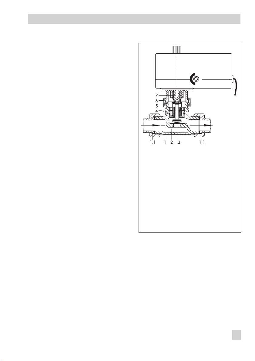
The medium flows through the single-seated
globe valve in the direction indicated by the
arrow. The position of the plug (3) determines the flow rate across the area released
between plug and valve seat (2).
The linear actuating force is transmitted directly over the actuator stem (7) to the plug
stem (5). When the actuator stem extends,
the valve plug (3) moves in the closing direction. The plug stem follows the actuator stem
owing to the force of the valve spring (4) as
the actuator stem retracts, causing the valve
to open.
-
Design and principle of operation
-
-
1 Valve body
1.1 Connection nut with gasket and
welding ends (accessories)
2 Seat
3 Plug
4 Valve spring
5 Plug stem
6 Coupling nut
7 Actuator stem
Fig. 1 · Type 3222 N/5857 Control Valve
Type 5857
Actuator
EB 5867 EN 5
Page 6

Design and principle of operation
2.1 Technical data for Type 3222 N Globe Valve
Nominal size DN 15
Connection ISO 228/1-G ¾ B
Threaded ends G ½
Type of end connections (optional)
Nominal pressure PN 16
K
VS
coefficient
Standard 2.5
Special version 0.25 · 0.4 · 0.63 · 1 · 1.6
Valve travel 6 mm
Characteristic Equal percentage
Pressure balancing None
Max. perm. differential pressure Δp 6 bar
1 Metal sealing
K
≤
Type of sealing
VS
K
= 1.6 and 2.5 Soft sealing
VS
Leakage rate (Class I acc. to IEC 60534) < 0.05 % of K
Max. permissible temperature 120 °C
Max. permissible
medium temperature
Treated water 120 °C
Non-flammable gases 80 °C
z value 0.43
Materials
Valve body CW602N (brass)
Plug
Up to K
K
= 1 1.4305
VS
= 1.6 and 2.5 1.4305 with EPDM seal
VS
Plug stem 1.4305
Seat
Up to K
K
= 1 1.4305
VS
= 1.6 and 2.5 CW602N (brass)
VS
Valve spring 1.4310 K
Welding ends 1.0254 (St 37)
Threaded ends Brass
Soldering ends CC491K (red brass, Rg 5)
Intermediate insulating piece 1.4305, CW617N (brass), PTFE, EPDM, FPM
Welding ends
Soldering ends
coefficient
VS
6 EB 5867 EN
Page 7

Design and principle of operation
2.1.1 Nameplate 2.1.2 Customer inquiries
SAMSON
2
4
Kvs
1 Type designation
2 Configuration ID (Var.-ID)
3 Date of manufacture
4 Model number
5 Max. permissible temperature
coefficient
6K
VS
7 Max. permissible differential pressure
p
Δ
1
3
5
76
Please submit the following details:
Type designation
4
Configuration ID (Var.-ID)
4
Date of manufacture
4
EB 5867 EN 7
Page 8

Installation
3 Installation
If the valve and actuator are delivered sepa
rately, first install the valve in the pipeline
and then mount the actuator.
3.1 Mounting position
Choose the place of installation where
4
the ambient temperature does not ex
ceed or fall below the permissible limits
specified for the actuator and that allows
you to freely access the control valve
even after the entire plant has been com
pleted.
Flush the pipeline thoroughly before in-
4
stallation.
Never install the valve with the actuator
4
suspended downwards.
Install a strainer (SAMSON Type 2 NI)
4
upstream of the control valve to prevent
any sealing parts, weld spatter or other
foreign matter carried along by the process medium from impairing the proper
functioning of the valve, in particular, the
tight shut-off.
The valve must be installed free of stress.
4
If necessary, support the piping near the
connections.
3.3 Additional installation
-
-
-
instructions
We recommend to install a hand-operated
shut-off valve both upstream of the strainer
and downstream of the control valve to be
able to shut down the plant for cleaning and
maintenance, and when the plant is not
used for longer periods of time.
3.2 Strainer
Install the strainer with the filter element
4
facing downwards upstream of the valve
inlet.
Choose the place of installation to allow
4
enough space to remove the filter.
Install the strainer with the flow direction
4
as indicated by the arrow on the body.
8 EB 5867 EN
Page 9

Combination with Type 5857 Electric Actuator
4 Combination with Type 5857 Electric Actuator
4.1 Technical data for actuator
Type 5857 Actuator Version Three-point stepping version With digital positioner
Connection to valve Force-locking Force-locking
Rated travel 6 mm 6 mm
2)
Transit time for rated travel 20 s
30/20
Nominal thrust 300 N 300 N
Power supply
230 V (±10 %), 50 Hz
24 V (±10 %), 50 Hz
24VAC(±10 %), (50 and 60 Hz)
24 V DC (±10 %)
Power consumption Approx. 3 VA 5 VA
Manual override Yes Yes
Permissible ambient temperature 0 to 50 °C 0 to 50 °C
Permissible storage temperature –20 to 70 °C –20 to 70 °C
Degree of protection IP 42 IP 42
Protection class II II
Noise immunity EN 61000-6-2 EN 61000-6-2
Noise emission EN 61000-6-3 EN 61000-6-3
Weight Approx. 0.7 kg Approx. 0.7 kg
Digital positioner –
Input signal
Position feedback 0 to 10 V
–
0 to 10 V
Characteristic Linear
1)
Value adjustable in TROVIS-VIEW Configuration and Operator Interface.
Refer to EB 5857 EN for more details (also included in TROVIS-VIEW).
2)
Default setting
3)
10 s applies to 24 V DC (–0 %, +10 %) for
Transit time for rated travel
setting
/10 s
1)
1)
1)
1)
3)
EB 5867 EN 9
Page 10

Combination with Type 5857 Electric Actuator
Handwheel
Travel
indicator
NOTICE
The handwheel is used to move the actuator
stem. Only operate the handwheel when the
actuator is in the de-energized state.
In the version with digital positioner, do not op
erate the handwheel while the actuator is in service (absolute travel adjustment, see
EB 5857 EN), otherwise the feedback signal will
be shifted.
Fig. 2 · Manual override of Type 5857
4.2 Mounting the actuator on the
valve
4.3 Electrical connection
DANGER!
Risk of electric shock!
When installing electric cables, you are
required to observe the regulations
governing electrical power plant
installation according to
DIN VDE 0100 as well as the
regulations of your local power supply
company.
Use a suitable power supply which
guarantees that no dangerous voltages
-
reach the device in normal operation
or in case of a fault in the system or
any other system parts.
Connect the actuator to the electrical
network only after the power supply is
first switched off. Make sure the power
cannot be switched on unintentionally!
Especially when a 24 V voltage supply
is used, wires with sufficiently large
wire cross-sections must be used to
guarantee that the permissible voltage
tolerances of
10 % are not exceeded!
±
1. Turn the handwheel (Fig. 2) counter
-
clockwise only after disconnecting the
actuator from the power supply to re
tract the actuator stem as far as it will
go.
2. Place the actuator on the valve connec
tion or the intermediate insulating piece
and secure with the coupling nut (tight
ening torque 20 Nm).
10 EB 5867 EN
-
-
-
Page 11

Three-point stepping version
Connect the cable as shown in Fig. 3,
4
observing the following instructions.
The control signals of the connected con
troller are connected to the terminals eL
and aL:
If a voltage is applied to eL, the ac
4
tuator stem retracts into the actuator
(direction of action ”Stem retracts“).
If a voltage is applied to aL, the ac
4
tuator stem extends out of the actua
tor (direction of action “Stem ex
tends“).
Important note:
Decoupling capacitors Ce in the output
4
circuit of the connected controller may
not exceed a value of 2.5 nF in order to
guarantee the proper functioning of the
actuator.
Combination with Type 5857 Electric Actuator
Controller
L
Actuator
-
Ce Ce
eL
aL
-
-
-
-
N
aL eL
BNWH GN
eL Actuator stem retracts
aL Actuator stem extends
WH white
BN brown
GN green
Fig. 3 · Electrical connection
(version with three-point stepping signal)
EB 5867 EN 11
Page 12

Combination with Type 5857 Electric Actuator
Version with digital positioner
WARNING!
Directly after connecting the voltage to the
actuator, a zero calibration is automatically
performed when the absolute travel adjust
ment is set (state of delivery), causing the
actuator stem to move.
Do not touch the actuator stem or obstruct it
to avoid risk of injury to hands or fingers.
For 24 V DC connection
_+_
Feedback,
output
++
Control
signal
24 V DC 0...10 V 0...10 V
_
OG YE RD BK BN GN
NOTICE
During zero calibration, the control valve
moves through a part of the travel range.
As a result, do not connect the wires of the
actuator while a process is running. Instead,
close the shut-off valves in the plant first.
Connect the 6-wire cable according to
Fig. 4.
For 24 V AC connection
_+_
Feedback,
output
+
Control
signal
24 V AC 0...10 V 0...10 V
NL
OG YE RD BK BN GN
M
Fig. 4 · Electrical connection – Version with digital positioner
12 EB 5867 EN
M
OG orange
YE yellow
RD red
BK black
BN brown
GN green
Page 13

5 Maintenance
WARNING!
For maintenance work on the valve, make
sure the relevant section of the pipeline is
depressurized and, depending on the pro
cess medium, drained as well.
For high medium temperatures, allow the
section of the pipeline to cool down before
you start.
Make sure the control signal for the actuator
is switched off.
The control valve is subject to natural wear.
Depending on the conditions the valve is operated in, it needs to be checked at regular
intervals.
If leakage to the atmosphere occurs, disassemble the valve and replace the damaged
parts.
-
Maintenance
EB 5867 EN 13
Page 14
Dimensions in mm and weights
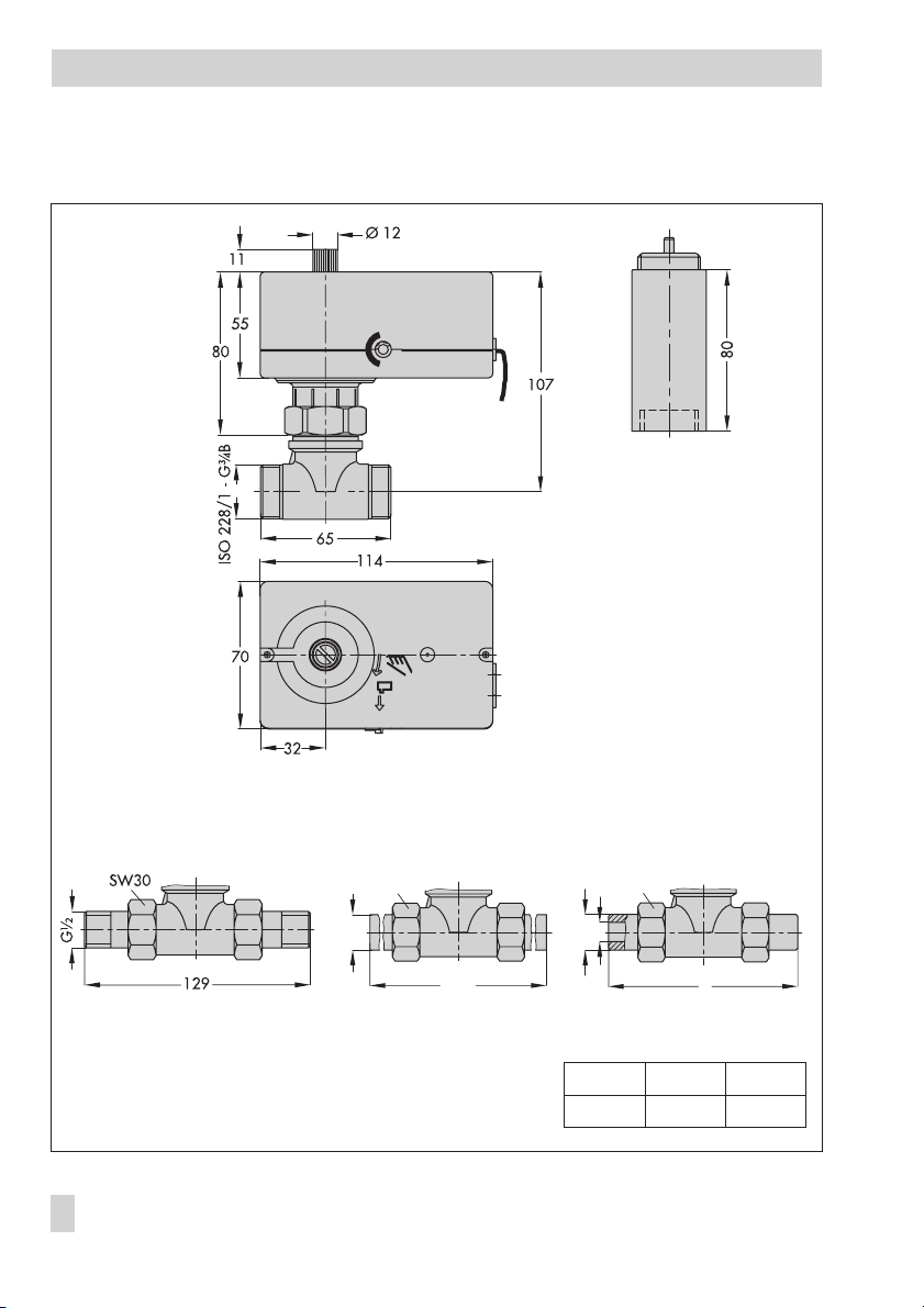
6 Dimensions in mm and weights
Intermediate
insulating piece
Type 3222 N/5857 (basic version)
Type 3222 N Valve with Type 5857 Actuator
Version with threaded ends
Weights:
Valve without actuator: Approx. 0.3 kg
Valve with actuator: Approx. 1.0 kg
14 EB 5867 EN
SW30
Ø21.3
210
Version with welding ends
SW30
di
Ø21.3
L
Version with soldering ends
Inside∅di 15 18
Length L 107 103
Page 15

EB 5867 EN 15
Page 16

SAMSON AG · MESS- UND REGELTECHNIK
Weismüllerstraße 3 · 60314 Frankfurt am Main · Germany
Phone: +49 69 4009-0 · Fax: +49 69 4009-1507
Internet: http://www.samson.de
EB 5867 EN
2009-11
 Loading...