

Samson 3222/5857, 3222/5824, 3222/5825, 3222/5757-3, 3222/5757-7 Mounting And Operating Instructions
...Page 1
Mounting and
Operating Instructions
EB 5866 EN
Translation of original instructions
Edition July 2016
Type3222/5857
Type3222/5757-3
Type3222/5757-7
Type3222/5825
Type3222/5725-7
Type3222/2780-1
Type3222/2780-2 with Type3760
Positioner
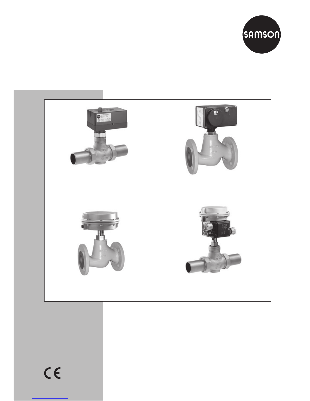
Electric Control Valves
Types 3222/5857, 3222/5824, 3222/5825, 3222/5757-3,
3222/5757-7, 3222/5724-3, 3222/5724-8, 3222/5725-3,
3222/5725-7, 3222/5725-8
Pneumatic Control Valves
Type3222/2780
Page 2

2 EB 5866 EN
Note on these mounting and operating instructions
These mounting and operating instructions assist you in mounting and operating the device
safely. The instructions are binding for handling SAMSON devices.
Î For the safe and proper use of these instructions, read them carefully and keep them for
later reference.
Î If you have any questions about these instructions, contact SAMSON‘s After-sales Service
Department (aftersalesservice@samson.de).
The mounting and operating instructions for the devices are included in
the scope of delivery. The latest documentation is available on our website
(www.samson.de) > Product documentation. You can enter the document
number or type number in the [Find:] eld to look for a document.
Denition of signal words
Hazardous situations which, if not avoided,
will result in death or serious injury
Hazardous situations which, if not avoided,
could result in death or serious injury
Property damage message or malfunction
Additional information
Recommended action
DANGER
!
WARNING
!
NOTICE
!
Note
Tip
Page 3

Contents
EB 5866 EN 3
1 Safety instructions and measures ...................................................................5
1.1 Notes on possible severe personal injury .........................................................8
1.2 Notes on possible personal injury ...................................................................9
1.3 Notes on possible property damage ..............................................................10
2 Markings on the device ...............................................................................11
2.1 Valve nameplate ..........................................................................................11
2.2 Actuator nameplate ......................................................................................11
3 Design and principle of operation ................................................................12
3.1 Fail-safe action ............................................................................................12
3.2 Versions ......................................................................................................14
3.3 Technical data .............................................................................................16
4 Preparation .................................................................................................22
4.1 Unpacking ..................................................................................................22
4.2 Transporting and lifting ................................................................................22
4.2.1 Transporting ................................................................................................22
4.2.2 Lifting ..........................................................................................................22
4.3 Storage .......................................................................................................22
4.4 Preparation for installation ............................................................................23
5 Mounting and start-up ................................................................................. 24
5.1 Installing the valve into the pipeline ...............................................................24
5.1.1 Checking the installation conditions ...............................................................24
5.1.2 Additional ttings .........................................................................................26
5.1.3 Installing the control valve .............................................................................26
5.2 Mounting the actuator onto the valve .............................................................27
5.2.1 Connecting the actuator ................................................................................27
5.2.2 Conguring the actuator ...............................................................................28
5.3 Quick check ................................................................................................28
6 Operation ...................................................................................................29
7 Servicing.....................................................................................................30
7.1 Preparation for return shipment .....................................................................30
7.2 Ordering spare parts and operating supplies .................................................30
Page 4

4 EB 5866 EN
Contents
8 Malfunctions ...............................................................................................31
8.1 Troubleshooting ...........................................................................................31
8.2 Emergency action ........................................................................................32
9 Decommissioning and disassembly ..............................................................33
9.1 Decommissioning .........................................................................................33
9.2 Removing the valve from the pipeline .............................................................33
9.3 Removing the actuator from the valve ............................................................34
9.4 Disposal ......................................................................................................34
10 Appendix ....................................................................................................35
10.1 After-sales service ........................................................................................35
10.2 Certicates ..................................................................................................35
Page 5

EB 5866 EN 5
Safety instructions and measures
1 Safety instructions and measures
Intended use
The SAMSON Type3222 Valve is designed for use in temperature control circuits in HVAC
plants (e.g. for DHW heating). The valve is primarily combined with the following SAMSON
actuators:
− As electric control valve: Type3222/5857, Type3222/5824, Type3222/5825,
Type3222/5757-3, Type3222/5757-7, Type3222/5724-3, Type3222/5724-8,
Type3222/5725-3, Type3222/5725-7 and Type3222/5725-8
− As pneumatic control valve: Type3222/2780
The valve with its actuator is designed to operate under exactly dened conditions (e.g. operating pressure, process medium, temperature). Therefore, operators must ensure that the control valve is only used in applications that meet the specications used for sizing the valve at
the ordering stage. In case operators intend to use the control valve in other applications or
conditions than specied, SAMSON must be contacted.
SAMSON does not assume any liability for damage resulting from the failure to use the
valve for its intended purpose or for damage caused by external forces or any other external
factors.
Î Refer to the technical data and nameplate for limits and elds of application as well as
possible uses.
Reasonably foreseeable misuse
The control valve is not suitable for the following applications:
− Use outside the limits dened during sizing and in the technical data
− For Type3222/2780 Control Valve: use outside the limits dened by the valve accesso-
ries mounted on the control valve
Furthermore, the following activities do not comply with the intended use:
− Use of non-original spare parts
− Performing servicing and repair work not described in these instructions
Page 6

6 EB 5866 EN
Safety instructions and measures
Qualications of operating personnel
The control valve must be mounted, started up, serviced, and repaired by fully trained and
qualied personnel only; the accepted industry codes and practices are to be observed. According to these mounting and operating instructions, trained personnel refers to individuals
who are able to judge the work they are assigned to and recognize possible hazards due to
their specialized training, their knowledge and experience as well as their knowledge of the
applicable standards.
Personal protective equipment
We recommend wearing the following protective equipment:
− Protective clothing and gloves in applications with hot or cold media
Î Check with the plant operator for details on further protective equipment.
Revisions and other modications
Revisions, conversions or other modications to the product are not authorized by SAMSON.
They are performed at the user's own risk and may lead to safety hazards, for example. Furthermore, the product may no longer meet the requirements for its intended use.
Safety features
In combination with the Type5825 Electric Actuator and with the TROVIS5725-3, TROVIS5725-7, and TROVIS5725-8 Electric Actuators with Process Controllers, the following
safety feature exists: upon failure of the power supply, the valve moves to a dened fail-safe
position (see section3.1). The direction of action of the fail-safe action is dened by the actuator version (see associated actuator documentation).
In combination with the Type2780 Pneumatic Actuator, the following safety feature exists:
upon failure of the air supply, the valve moves to a certain fail-safe position (see section3.1).
The fail-safe action corresponds with the direction of action. The fail-safe action of SAMSON
actuators is specied on the actuator nameplate (see actuator documentation).
Warning against residual hazards
To avoid personal injury or property damage, plant operators and operating personnel must
prevent hazards that could be caused in the control valve by the process medium, the operating pressure, the signal pressure or by moving parts by taking appropriate precautions. They
must observe all hazard statements, warning and caution notes in these mounting and operating instructions, especially for installation, start-up, and servicing.
Page 7

EB 5866 EN 7
Safety instructions and measures
Responsibilities of the operator
The operator is responsible for proper operation and compliance with the safety regulations.
Operators are obliged to provide these mounting and operating instructions as well as the
referenced documents to the operating personnel and to instruct them in proper operation.
Furthermore, operators must ensure that operating personnel or third persons are not exposed to any danger.
Responsibilities of operating personnel
Operating personnel must read and understand these mounting and operating instructions as
well as the referenced documents and observe the hazard statements, warning, and caution
notes specied in them. Furthermore, the operating personnel must be familiar with the applicable health, safety and accident prevention regulations and comply with them.
Referenced standards and regulations
The control valves comply with the requirements of the European Pressure Equipment Directive 2014/68/EU. Valves with a CE marking have a declaration of conformity which includes information about the applied conformity assessment procedure. This declaration of
conformity is included in the Appendix of these instructions (see section10.2).
The electric actuators are designed for use in low voltage installations. For wiring, maintenance, and repair, observe the relevant safety regulations.
Referenced documentation
The following documents apply in addition to these mounting and operating instructions:
− Mounting and operating instructions for mounted actuator, e.g. SAMSON actuators:
u EB5857 for Type5857
uEB5824-1/-2 for Type5824 and Type5825
uEB5757-X for TROVIS5757-X
uEB5724 for TROVIS5724-3 and TROVIS5725-3
uEB5724-8 for TROVIS5724-8 and TROVIS5725-8
uEB5725-7 for TROVIS5725-7
u EB5840 for Type2780
− For Type3222/2780 Control Valve: mounting and operating instructions for mounted
valve accessories (positioner, solenoid valve etc.)
Page 8

8 EB 5866 EN
Safety instructions and measures
1.1 Notes on possible severe personal injury
DANGER
!
Risk of bursting in pressure equipment.
Control valves and pipelines are pressure equipment. Improper opening can lead to
valve components bursting.
Î Before starting any work on the control valve, depressurize all plant sections
concerned and the valve.
Î Drain the process medium from all the plant sections concerned as well as the
valve.
Î Wear personal protective equipment.
Risk of electric shock.
Î Do not remove any covers to perform adjustment work on live parts.
Î Before performing any work on the device and before opening the device, discon-
nect the power supply and protect it against unintentional reconnection.
Î Only use power interruption devices that are protected against unintentional recon-
nection of the power supply.
Î The electric actuators are protected against spray water (IP54). Avoid jets of water.
Page 9

EB 5866 EN 9
Safety instructions and measures
1.2 Notes on possible personal injury
WARNING
!
Crush hazard arising from moving parts.
The pneumatic control valve (Type3222/2780) contains moving parts (actuator and
plug stems), which can injure hands or ngers if inserted into the valve.
Î While working on the control valve, disconnect and lock the pneumatic air supply
as well as the control signal.
Risk of personal injury when the pneumatic actuator vents.
While the valve is operating, the pneumatic actuator (Type2780) may vent during
closed-loop control or when the valve opens or closes.
Î Install the control valve in such a way that the actuator does not vent at eye level.
Î Use suitable silencers and vent plugs.
Î Wear eye protection when working in close proximity to the control valve.
Risk of personal injury due to residual process medium in the valve.
While working on the valve, residual process medium can escape and, depending on
its properties, may lead to personal injury, e.g. burns.
Î If possible, drain the process medium from all the plant sections concerned and the
valve.
Î Wear protective clothing and gloves.
Risk of burn injuries due to hot components and pipelines.
Depending on the process medium, valve components, and pipelines may get very hot
and cause burn injuries.
Î Allow components and pipelines to cool down.
Î Wear protective clothing and gloves.
Page 10

10 EB 5866 EN
Safety instructions and measures
1.3 Notes on possible property damage
NOTICE
!
Risk of damage to the electric control valve due to the power supply exceeding the
permissible tolerances.
The electric control valves are designed for use according to regulations for low-voltage installations.
Î Observe the permissible tolerances of the power supply. See associated actuator
documentation.
Risk of valve damage due to contamination (e.g. solid particles) in the pipeline.
The plant engineering company is responsible for cleaning the pipelines in the plant.
Î Flush the pipelines before start-up.
Î Observe the maximum permissible pressure for valve and plant.
Risk of valve damage due to unsuitable medium properties.
The valve is designed for a process medium with certain properties (e.g. water, oil,
steam).
Î Only use the process medium that meets the specications used for sizing the valve.
Page 11
EB 5866 EN 11
Markings on the device
2 Markings on the device
2.1 Valve nameplate
SAMSON
1
2 3
4 5
kvs 6 Δp 7
1 Type designation
2 Conguration ID
3 Date of manufacture
4 Model number
5 Max. permissible temperature
6 K
VS
coefcient
7 Max. perm. differential pressure
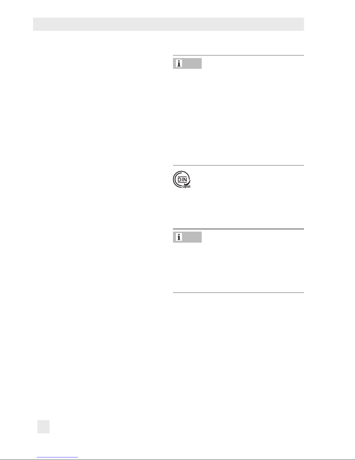
The nameplate (48) is afxed to the valve
body (see Fig.1).
48
Fig.1: Location of the nameplate
2.2 Actuator nameplate
See associated actuator documentation.
Page 12
12 EB 5866 EN
Design and principle of operation
3 Design and principle of oper-
ation
The medium ows through the single-seated
globe valve in the direction indicated by the
arrow. The position of the plug determines
the ow rate across the area released between plug (1) and seat (5). The valve is
opened by the valve spring when the actuator stem retracts. The plug is moved by
changing the control signal applied to the
actuator. The valve and actuator have a
force-locking connection.
A special version (see Fig.4) is available for
water above 150°C and steam.
3.1 Fail-safe action
When the Type3222 Valve is combined with
one of the following actuators, the valve
moves to the fail-safe position up upon failure of the air supply or power supply:
− Type5825 Electric Actuator
− TROVIS5725-3 and TROVIS5725-7
Electric Actuators with Process Controllers
− Type 2780 Pneumatic Actuator
The control valve has two different fail-safe
positions:
− Actuator stem extends: upon power sup-
ply or air supply failure, the actuator
stem extends.
The TROVIS5725-3, TROVIS5725-7, and
TROVIS8725-8 Electric Actuators with Process Controllers in the version with
force-locking attachment and the Type5825
Electric Actuator with "actuator stem extends" fail-safe action are tested by the German technical surveillance association TÜV
according to DINEN14597 in combination
with the SAMSON Type3222 Valve. The
registration number is available on request.
− Actuator stem retracts: upon power sup-
ply or air supply failure, the actuator
stem retracts.
The fail-safe action of pneumatic actuators
can be reversed (see associated actuator
documentation). The fail-safe action of electric actuators (with process controllers) is already determined at the ordering stage.
Note
Note
Page 13

EB 5866 EN 13
Design and principle of operation
1
5
3
7
1 Plug
3 Body
5 Seat
7 O-ring
8 Connecting piece
11 Guide nipple
14 Insulating section
15 Insulating pipe
1
5
3
7
11
8
5
1
14
15
11
Fig.2: Type3222/2780-1
Fig.3: Type3222/5875, Type3222/5757-3,
Type3222/5757-7 · Version for water,
oil, and liquids
Fig.4: Type3222/5824, Type3222/5724-3 · Version
for water above 150°C and steam
Page 14

14 EB 5866 EN
Design and principle of operation
3.2 Versions
Intermediate insulating piece
An intermediate insulating piece is available
for insulated pipes.
Electric actuators
The electric actuators can be controlled either using a three-step signal or, in the version with positioner, with continuous signals
adjustable in the range from 0 to 20mA or
from 0 to 10V. Various electrical accessories
can be optionally installed.
Type5825 Actuator is able to perform a failsafe action. Refer to Table1.
Electric actuators with process controllers
Electric actuators with process controllers are
a combination of an electric actuator and a
digital process controller. The TROVIS57573, TROVIS5724-3, and TROVIS5725-3
Electric Actuators with Process Controller are
suitable for domestic hot water heating.
TROVIS5757-7 and TROVIS5725-7 are
suitable for heating and cooling applications.
TROVIS5724-8 and TROVIS5725-8 have
two PID control modules and are readywired for heating and cooling applications.
TROVIS5725-3, TROVIS5725-7, and
TROVIS5725-8 Actuators are able to perform a fail-safe action (see Table1).
Pneumatic actuators
The Type2780-1 Pneumatic Actuator uses a
control signal from 0.4 to 1bar and
Type2780-2 uses a control signal from 0.4
to 2bar which is applied to the signal pressure connection.
The pneumatic actuators require a supply
pressure of at least 0.2bar above the maximum bench range. All actuators are available for fail-safe action "Actuator stem extends (FA)" or "Actuator stem retracts (FE)".
Page 15
EB 5866 EN 15
Design and principle of operation
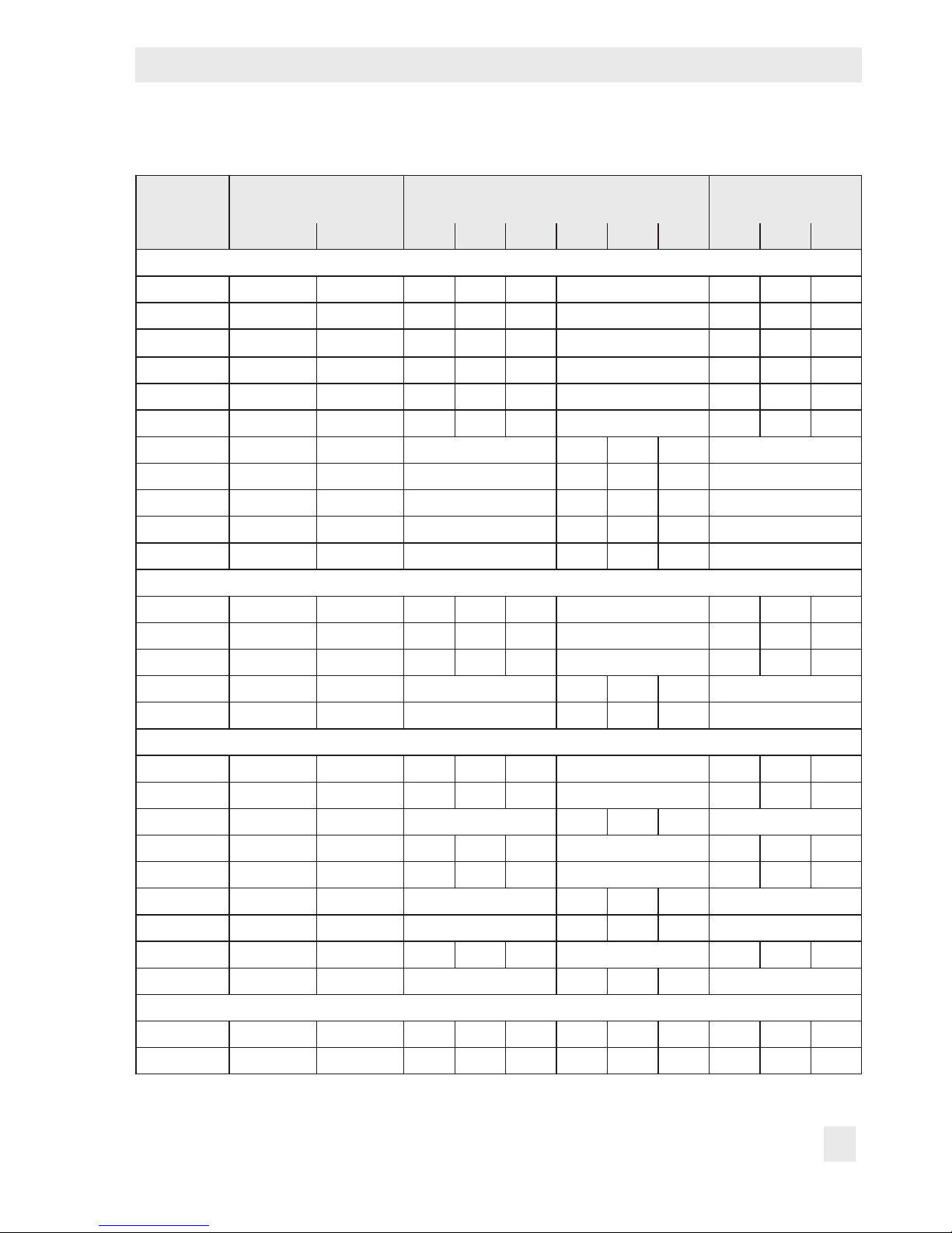
Table1: Available versions and possible combinations (valve/actuator)
Type/TROVIS
Fail-safe action:
Actuator stem Nominal size DN Thread size G
Extends Retracts 15 20 25 32 40 50 ½ ¾ 1
Electric actuators
5857 – – • • • – • • •
5824-10 – – • • • – • • •
5824-13
1)
– – • • • – • •
•
5825-10 • – • • • – • • •
5825-13
1)
• – • • • – • • •
5825-15 – • • • • – • • •
5824-20 – – – • • • –
5824-23 – – – • • • –
5825-20 • – – • • • –
5825-23 • – – • • • –
5825-25 – • – • • • –
Electric actuators with process controllers for domestic hot water heating
5757-3 – – • • • – • • •
5724-310 – – • • • – • • •
5725-310 • – • • • – • • •
5724-320 – – – • • • –
5725-320 • – – • • • –
Electric actuators with process controller for heating and cooling applications
5757-7 – – • • • – • • •
5724-810 – – • • • – • • •
5724-820 – – – • • • –
5725-710 • – • • • – • • •
5725-715 – • • • • – • • •
5725-720 • – – • • • –
5725-725 – • – • • • –
5725-810 • – • • • – • • •
5725-820 • – – • • • –
Pneumatic actuators
2780-1 • • • • • • • • • • •
2780-2 • • • • • • • • • • •
1)
Version with half transit time
Page 16

16 EB 5866 EN
Design and principle of operation
3.3 Technical data
The nameplates on the valve and actuator provide information on the control valve version.
See section2.1 and the associated actuator documentation.
Table2: Technical data for Type3222
Nominal size
Globe valve with male thread connec-
tion or with anged body
DN
15 20 25 32 40 50
Connection size
Globe valve with female thread
G ½ ¾ 1 – – –
Nominal pressure PN 25
Seat-plug seal
Metal seal for K
VS
≤2.5
Soft seal for KVS ≥3.6
Rated travel mm 6 12
Rangeability 50 : 1
Leakage class according to IEC60534-4 Class I (≤0.05% of K
VS
coefcient)
Compliance
·
Version for water, oil and other liquids
Max. permissible temperature 150°C
1)
Max. permissible differential pressure ∆p
Type5824/5825, TROVIS5724-3/
5724-8/5725-3/ 5725-7/5725-8,
Type2780
bar 20 20 20 12/16
4)
12 12
Type5857, TROVIS5757-3,
TROVIS5757-7
bar 20 20 20 – – –
Version for water above 150°C and steam
Max. permissible temperature 200°C
Max. permissible differential pressure ∆p
Type5824/5825, TROVIS5724-3/
5724-8/5725-3/5725-7/5725-8,
Type2780
bar 20 · 10 with 3.6≤K
VS
≤8 8 8 8
Type5857, TROVIS5757-3,
TROVIS5757-7
bar
20
2)
·
5
3)
5 5 – – –
1)
Use an intermediate insulating piece (see section5.1.2, Intermediate insulating piece)
2)
Differential pressure with KVS = 1 and 1.6
3)
Differential pressure with KVS = 2.5 and 4
4)
Applies to KVS = 10
Page 17

EB 5866 EN 17
Design and principle of operation
Table3: Nominal sizes and K
VS
coefcients
Nominal size
Globe valve with male
thread connection or
with anged body
DN 15 20 25 32 40 50
Connection size
Globe valve with female
thread
G ½ ¾ 1 – – –
K
VS
coefcients 4
1)
· 3.6
2)
6.3
1)
·
5.7
2)
8
1)
·
7.2
2)
16
1)
20
1)
25
1)
Reduced K
VS
coefcients
0.1· 0.16 · 0.25
· 0.4 · 0.63 ·
1.0 · 1.6 · 2.5
1.0 · 1.6 · 2.5 ·
4
1)
· 3.6
2)
10
3)
– –
Rated travel
mm
6 6 6 12 12 12
1)
Version with male thread connection or with anged body
2)
Version with female thread
3)
6mm rated travel
Table4: Materials
Valve body CC499K (CuSn5Zn5Pb2-C)
Version with anged body EN-GJS-400-18-LT (GGG-40.3)
Seat Stainless steel 1.4305
Plug
1.4305/CW602N with soft seal
1.4305 with 0.1≤K
VS
≤2.5
Valve spring Stainless steel 1.4310K
Packing EPDM/FPM (FKM) · Oil-resistant version: FPM
Welding ends St 37
Threaded ends CC491K (red brass)
Screwed-on anges St 37.2
Noise emission
SAMSON is unable to make general statements about noise emission as it depends on the
valve version, plant facilities, and process medium. On request, SAMSON can perform calculations according to IEC60534, Part8-3 and Part8-4 or VDMA24422 (edition89).
Page 18

18 EB 5866 EN
Design and principle of operation
Dimensions and weights
Table5 provides a summary of the dimensions and weights of the valve. The lengths and
heights in the dimension diagrams are shown on page19 onwards.
Table5: Dimensions and weights for Type3222 Valve
Valves with male thread connection
Nominal size DN 15 20 25 32 40 50
Length L mm 65 70 75 100 110 130
Height H2 mm 45.5 45.5 45.5 94 94 94
Version for water above 150°C
and steam or version with
intermediate insulating piece
140 140 140 185 185 185
Height H3 mm 30 30 30 55 55 55
Valves with welding ends
Thread size R G ¾ 1 1¼ 1¾ 2 2½
Pipe Ød mm 21.3 26.8 33.7 42 48 60
Width across ats SW 30 36 46 59 65 82
Length L1 mm 210 234 244 268 294 330
Weight without actuator kg (approx.) 1.4 1.8 2.3 4.0 4.4 6.8
Version for water above 150°C
and steam or version with
intermediate insulating piece
1.9 2.3 2.8 4.5 4.9 7.3
Valves with threaded ends
Length L2 mm 129 144 159 180 196 228
Male thread A G ½ ¾ 1 1¼ 1½ 2
Width across ats SW 30 36 46 59 65 82
Weight without actuator kg (approx.) 1.4 1.8 2.3 4.0 4.4 6.8
Version for water above 150°C
and steam or version with
intermediate insulating piece
1.9 2.3 2.8 4.5 4.9 7.3
Valves with anges
Width across ats SW 30 36 46 59 65 82
Length L3 mm 130 150 160 180 200 230
Weight without actuator kg (approx.) 2.5 3.4 4.1 6.9 7.7 10.7
Version for water above 150°C
and steam or version with
intermediate insulating piece
3.0 3.9 4.6 7.4 8.2 11.2
Page 19

EB 5866 EN 19
Design and principle of operation
Valves with female thread
Connection size G ½ ¾ 1 –
Width across ats SW 30 36 46 –
Length L4 mm 65 75 90 –
Female thread G ½ ¾ 1 –
Weight without actuator kg (approx.) 1.2 1.4 1.5 –
Version for water above 150°C
and steam or version with
intermediate insulating piece
1.7 1.9 2.0 –
Valves with anged body
Nominal size DN 15 20 25 32 40 50
Height H2 mm 45.5 45.5 45.5 94 94 92
Length L3 mm 130 150 160 180 200 230
Weight without actuator kg (approx.) 2.5 3.4 4.1 6.9 8.4 11.6
Version for water above 150°C
and steam or version with
intermediate insulating piece
3.0 3.9 4.6 7.4 8.9 12.1
Dimensional drawings
SW
L2
A
SW
L4
G
80
Version with threaded ends Version with female thread Intermediate
insulating
piece
SW
L3
L3
H2
Version with anges Version with anges
Page 20

20 EB 5866 EN
Design and principle of operation
Dimension diagrams for electric control valves
Ø12
55
80
11
L
L1
H2
114 x 70
H3
R
d
SW
L
L1
146 x 103*
113
H2
H3
R
d
SW
Type3222/5857: DN15 to 25
Type3222/5757-3: DN15 to 25
Type3222/5757-7: DN15 to 25
Type3222/5824: DN15 to 50
Type3222/5825: DN15 to 50
Type3222/5724-3: DN15 to 50
Type3222/5724-8: DN15 to 50
Type3222/5725-3: DN15 to 50
Type3222/5725-7: DN15 to 50
Type3222/5725-8: DN15 to 50
* Dimensions for Types 5824-x3, 5825-x3
Actuators:
146 x 136
146 x 103*
113
L
L1
H2 + 80
H3
R
d
SW
Version for water above 150°C and steam
Type3222/5824: DN15 to 50
Type3222/5825: DN15 to 50
Type3222/5724-3: DN15 to 50
Type3222/5724-8: DN15 to 50
Type3222/5725-3: DN15 to 50
Type3222/5725-7: DN15 to 50
Type3222/5725-8: DN15 to 50
* Dimensions for Types 5824-x3, 5825-x3
Actuators:
146 x 136
Page 21

EB 5866 EN 21
Design and principle of operation
Dimension diagrams for pneumatic control valves
SW
R
d
L
L1
H3 H2 130
Ø168
SW
R
d
L
L1
230
Ø168
H2H3
Type3222/2780-1: DN15 to 50 Type3222/2780-2: DN15 to 50
Table6: Weights of electric actuators
Type 5857 5824 5825
Weight kg (approx.) 0.7 0.75 1.0
Table7: Weights of electric actuators with process controllers
TROVIS 5757-3/-7 5724-3/-8 5725-3/-7/-8
Weight kg (approx.) 0.7 1.1 1.3
Table8: Dimensions and weights for pneumatic actuators
Type 2780-1 2780-2
Actuator area cm² 120 120
Diaphragm ØD mm 170 170
Signal pressure connection a G
1
/
8
G
1
/
8
Weight kg (approx.) 2 3.2
Page 22

22 EB 5866 EN
Preparation
4 Preparation
After receiving the shipment, proceed as follows:
1. Check the scope of delivery. Compare
the shipment received against the delivery note.
2. Check the shipment for transportation
damage. Report any damage to SAMSON and the forwarding agent (refer to
delivery note).
4.1 Unpacking
Do not remove the packaging until immediately before installing the valve into the pipeline.
Proceed as follows to lift and install the
valve:
1. Remove the packaging from the valve.
2. Dispose of the packaging in accordance
with the valid regulations.
4.2 Transporting and lifting
SAMSON's After-sales Service department
can provide more detailed transport and lifting instructions on request.
4.2.1 Transporting
− Protect the control valve against external
inuences (e.g. impact).
− Protect the control valve against moisture
and dirt.
− Observe the permissible transportation
temperature of –20 to +65°C.
4.2.2 Lifting
Due to the low service weight, lifting equipment is not required to lift the valve (e.g. to
install it into the pipeline).
4.3 Storage
Risk of valve damage due to improper storage.
− Observe storage instructions.
− Avoid long storage times.
− Contact SAMSON in case of different stor-
age conditions or long storage periods.
We recommend regularly checking the control valve and the prevailing storage conditions during long storage times.
Storage instructions
− The control valves can be stored horizon-
tally.
− Protect the control valve against external
inuences (e.g. impact).
Note
Tip
NOTICE
!
Note
Page 23

EB 5866 EN 23
Preparation
− Protect the control valve against moisture
and dirt. Store it at a relative humidity of
less than 75%. In damp spaces, prevent
condensation. If necessary, use a drying
agent or heating.
− Make sure that the ambient air is free of
acids or other corrosive media.
− Observe the permissible storage tem-
perature from –20 to +65°C.
− Do not place any objects on the control
valve.
SAMSON's After-sales Service department
can provide more detailed storage instructions on request.
Special storage instructions for elastomers
Elastomer, e.g. actuator diaphragm
(Type2780 Pneumatic Actuator)
− To keep elastomers in shape and to pre-
vent cracking, do not bend them or hang
them up.
− We recommend a storage temperature of
15°C (59°F) for elastomers.
− Store elastomers away from lubricants,
chemicals, solutions, and fuels.
SAMSON's After-sales Service department
can provide more detailed storage instructions on request.
4.4 Preparation for installation
Proceed as follows:
Î Flush the pipelines.
The plant engineering company is responsible for cleaning the pipelines in the plant.
Î Check the valve to make sure it is clean.
Î Check the valve for damage.
Î Check to make sure that the type desig-
nation, valve size, material, pressure rating and temperature range of the valve
match the plant conditions (size and
pressure rating of the pipeline, medium
temperature etc.).
Î Check any mounted pressure gauges to
make sure they function.
Î When the valve and actuator are al-
ready assembled, check the bolted joints.
Components may loosen during transport.
Tip
Tip
Note
Page 24
24 EB 5866 EN
Mounting and start-up
5 Mounting and start-up
SAMSON valves are delivered ready for
use. The valve and actuator are delivered
separately and must be assembled on site.
The procedure to mount and start up the
valve are described in the following.
We recommend rst installing the valve into
the pipeline and mounting the actuator afterwards.
Risk of valve damage due to excessively high
or low tightening torques.
Observe the specied torques on tightening
control valve components. Excessively tightened torques lead to parts wearing out
quicker. Parts that are too loose may cause
leakage.
5.1 Installing the valve into the
pipeline
For medium temperatures above 150°C
only
the dark gray graphite seals supplied with
the valve are to be used. Do not use the UDP
seals available as accessories as they are
only suitable for temperatures up to 150°C.
5.1.1 Checking the installation
conditions
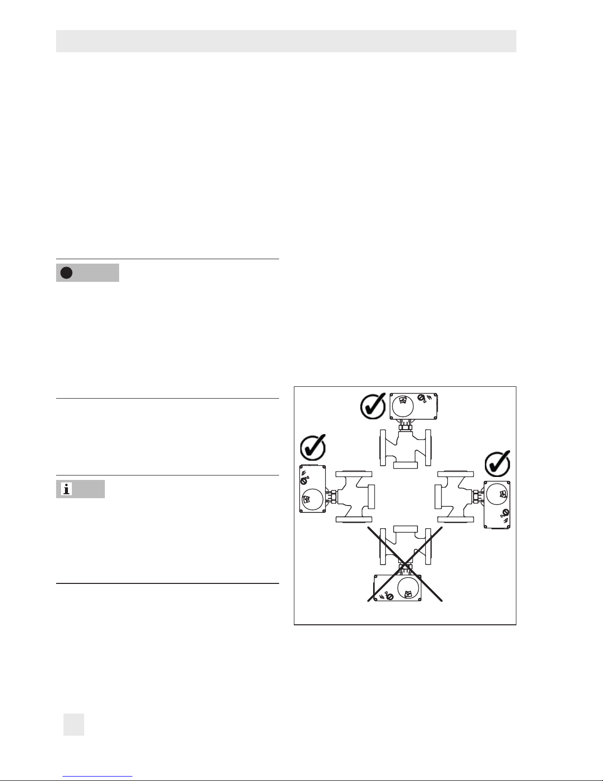
Mounting position
Generally, we recommend installing the
valve with the actuator upright and on top of
the valve.
For versions for water, oil, and other liquids,
the actuator must not be suspended downwards (see Fig.5).
In the following versions, the valve must be
installed with the actuator on top in a horizontal pipeline:
− Version for water above 150°C and
steam
Î Contact SAMSON if the mounting posi-
tion is not as specied here.
Fig.5: Mounting position
NOTICE
!
Note
Page 25

EB 5866 EN 25
Mounting and start-up
Support or suspension
Depending on the valve version and mounting position, the control valve and pipeline
must be supported or suspended. The plant
engineering company is responsible in this
case.
Premature wear and leakage due to insufcient support or suspension. In the following
versions, the control valve must be supported
or suspended:
− Valves that are not installed with the actua-
tor upright on top of the valve.
Attach a suitable support or suspension to
the valve.
Insulation of cold systems
To insulate cold systems, we recommend to
proceed as follows:
1. Fill the plant and carefully rinse it.
2. Shut down the plant and let it heat up
until all the condensation water has dried
off.
3. Mount and insulate the intermediate insulating piece (1990-1712).
Observe the following on installing the control valve:
Î Make sure that the electric actuator re-
mains accessible after installation.
Î Make sure that the plug stem can move
freely and does not touch the insulation.
Î Make sure that the actuator stem does
not touch the insulation.
The insulation thickness depends on the medium temperature and the ambient conditions. 50mm is a typical thickness.
Pipeline routing
To ensure the control valve functions properly, follow the installation instructions given
below:
Î Do not exceed the maximum permissible
ow velocity.
The plant engineering company is responsible for determining the maximum permissible ow velocity. SAMSON's After-sales Service department can support you to determine the ow velocity for your plant.
Î Install the valve free of stress and with the
least amount of vibrations as possible. If
necessary, attach supports to the valve.
Î Install the valve allowing sufcient space
to remove the actuator and valve or to
perform service and repair work on
them.
Vent plug (Type3222/2780 only)
Vent plugs are screwed into the exhaust air
ports of pneumatic devices. They ensure that
any exhaust air that forms can be vented to
the atmosphere (to avoid excess pressure in
the device). Furthermore, the vent plugs allow air intake to prevent a vacuum from
forming in the device.
NOTICE
!
Note
Note
Page 26

26 EB 5866 EN
Mounting and start-up
Î Locate the vent plug on the opposite side
to the workplace of operating personnel.
Risk of personal injury when the actuator
vents.
− Install the control valve in such a way that
the actuator does not vent at eye level.
− Use suitable silencers and vent plugs.
− Wear eye protection when working in
close proximity to the control valve.
Î On mounting valve accessories, make
sure that they can be operated from the
workplace of the operating personnel.
The workplace of operating personnel is the
location from which the valve, actuator and
any mounted valve accessories can be accessed to operate them.
5.1.2 Additional ttings
Strainer
We recommend installing a SAMSON
Type2NI Strainer upstream of the valve. It
prevents solid particles in the process medium from damaging the valve.
Î Make sure the direction of ow of the
strainer and valve are the same.
Î Install the strainer with the lter element
facing downwards.
Î Allow sufcient space to remove the lter.
Bypass and shut-off valves
We recommend installing a shut-off valve
both upstream of the strainer and downstream of the valve and setting up a bypass
line. The bypass line ensures that the plant
does not need to be shut down for service
and repair work on the valve.
Intermediate insulating piece
An intermediate insulating piece (1990-
1712) must be used under the following conditions:
− For medium temperatures from –15°C
(red brass) or –10°C (EN-GJS-400-18LT) to +5°C (actuators according to Table1)
− In networks with a constant medium tem-
perature >135°C (TROVIS5724-3,
TROVIS5724-8, TROVIS5725-3,
TROVIS5725-7, TROVIS5725-8,
Type5824, Type5825 Actuators)
− For liquids >120°C (TROVIS5757-3,
TROVIS5757-7, and Type5857 Actuators)
Î Do not insulate the actuator and the cou-
pling nut as well.
Î Only insulate the intermediate insulating
piece up to 25mm at the maximum.
5.1.3 Installing the control
valve
1. Close the shut-off valve in the pipeline
while the valve is being installed.
2. Remove any protective caps from the
valve ports before installing the valve.
WARNING
!
Note
Page 27

EB 5866 EN 27
Mounting and start-up
3. Lift the valve to the site of installation (see
section4.2). Observe the ow direction
through the valve. The arrow on the
valve indicates the direction of ow.
4. Version with anges: make sure that the
correct ange gaskets are used.
5. Version with threaded ends (female/
male thread) and anges: bolt the valve
to the pipeline free of stress.
Version with welding ends: weld the
valve free of stress into the pipeline.
6. Depending on the eld of application,
allow the valve to cool down to reach
ambient temperature before start up.
7. Slowly open the shut-off valve in the
pipeline after the valve has been installed.
Risk of valve damage due to a sudden pressure increase and resulting high ow velocities.
Slowly open the shut-off valve in the pipeline
during start-up.
8. Check the valve to ensure it functions
properly and that there is no leakage.
5.2 Mounting the actuator onto
the valve
Proceed as described in the actuator documentation if the valve and actuator have not
been assembled by SAMSON:
− Type5857 Electric Actuator uEB5857
− Type5824 Electric Actuator
uEB5824-1/-2
− Type5825 Electric Actuator
uEB5824-1/-2
− TROVIS5757-3 Electric Actuator with
Process Controller uEB5757
− TROVIS5724-3 Electric Actuator with
Process Controller uEB5724
− TROVIS5724-8 Electric Actuator with
Process Controller uEB5724-8
− TROVIS5725-8 Electric Actuator with
Process Controller uEB5724-8
− TROVIS5725-3 Electric Actuator with
Process Controller uEB5724
− TROVIS5757-7 Electric Actuator with
Process Controller uEB5757-7
− TROVIS5725-7 Electric Actuator with
Process Controller uEB5725-7
− Type2780 Pneumatic Actuator
uEB5840
Remove the mounted actuator before mounting the other actuator (see associated actuator documentation).
5.2.1 Connecting the actuator
Perform the electrical or pneumatic connection of the actuator as described in the associated actuator documentation.
NOTICE
!
Note
Page 28

28 EB 5866 EN
Mounting and start-up
5.2.2 Conguring the actuator
The electric actuator versions with positioner
as well as electric actuators with process
controllers can be adapted to the control
task.
Congure the actuator as described in the
associated actuator documentation.
For electric control valves with positioner, an
initialization needs to be performed after the
initial start-up (see associated documentation).
5.3 Quick check
SAMSON valves are delivered ready for
use. To test the valve's ability to function, the
following quick checks can be performed:
Travel motion
The movement of the actuator stem must be
linear and smooth.
Î Open and close the valve, observing the
movement of the actuator stem.
Î Apply the maximum and minimum con-
trol signals to check the end positions of
the valve.
Î Check the travel reading at the travel in-
dicator scale.
Fail-safe position with pneumatic actuators
Î Shut off the signal pressure line.
Î Check whether the valve moves to the
fail-safe position.
Fail-safe action for electric actuators and
electric actuators with process controllers
with fail-safe action
Î Switch off the power supply.
Î Check whether the valve moves to the
fail-safe position.
Pressure test
During the pressure test, make sure the following conditions are met:
− Retract the plug stem to open the valve.
− Observe the maximum permissible pres-
sure for valve and plant.
The plant engineering company is responsible for performing the pressure test.
SAMSON's After-sales Service department
can support you to plan and perform a pressure test for your plant.
Note
Note
Page 29

EB 5866 EN 29
Operation
6 Operation
Immediately after completing mounting and
start-up (see section5), the valve is ready for
use.
Type3222/2780: crush hazard arising from
moving parts (actuator and plug stem).
Do not insert hands or nger into the yoke
while the valve is in operation.
Type3222/2780: risk of personal injury
when the actuator vents.
Wear eye protection when working in close
proximity to the control valve.
Risk of burn injuries due to hot components
and pipeline.
Valve components and the pipeline may become very hot. Risk of burn injuries.
Wear protective clothing and gloves.
Type3222/2780: operation disturbed by a
blocked actuator or plug stem.
Do not impede the movement of the actuator
or plug stem by inserting objects into their
path.
WARNING
!
WARNING
!
WARNING
!
NOTICE
!
Page 30

30 EB 5866 EN
Servicing
7 Servicing
The control valve was checked by SAMSON
before it left the factory.
− The product warranty becomes void if ser-
vicing or repair work not described in
these instructions is performed without prior agreement by SAMSON's After-sales
Service department.
− Only use original spare parts by
SAMSON, which comply with the original
specications.
7.1 Preparation for return shipment
Defective valves can be returned to SAMSON for repair.
Proceed as follows to return valves to SAMSON:
1. Put the control valve out of operation (see
section9).
2. Remove any residual process medium.
3. Fill in the Declaration on Contamination,
which can be downloaded from our
website at uwww.samson.de > Services
> Check lists for after sales service >
Declaration on Contamination.
4. Send the control valve to your nearest
SAMSON subsidiary. SAMSON subsidiaries are listed on our website at
uwww.samson.de > Contact.
7.2 Ordering spare parts and
operating supplies
Contact your nearest SAMSON subsidiary
or the SAMSON After-sales Service department for information on spare parts, lubricants, and tools.
Note
Page 31

EB 5866 EN 31
Malfunctions
8 Malfunctions
Depending on the operating conditions, check the valve at certain intervals to prevent possible failure before it can occur. Operators are responsible for drawing up a test plan.
SAMSON's After-sales Service department can support you to draw up an inspection plan
for your plant.
8.1 Troubleshooting
Malfunction Possible reasons Recommended action
Actuator or plug stem does not
move on demand.
Actuator is blocked. Check attachment.
Unblock the actuator.
No or incorrect power supply
connected.
Check the power supply and
connections.
Signal pressure too low Check the signal pressure.
Check the signal pressure line for
leakage.
Actuator or plug stem does not
move through the whole range.
No or incorrect power supply
connected.
Check the power supply and
connections.
Signal pressure too low Check the signal pressure.
Check the signal pressure line for
leakage.
The valve leaks to the atmosphere (fugitive emissions).
Plug stem seal defective Contact SAMSON's After-sales
Service department.
Increased ow through closed
valve (seat leakage)
Dirt or other foreign particles
deposited between the seat and
plug.
Shut off the section of the pipeline and ush the valve.
Valve trim is worn. Contact SAMSON's After-sales
Service department.
Contact SAMSON's After-sales Service department for malfunctions not listed in the table.
Tip
Note
Page 32

32 EB 5866 EN
Malfunctions
8.2 Emergency action
The valve, on which the electric actuator with
fail-safe action is mounted, is moved to its
fail-safe position upon power supply failure
(voltage supply, signal pressure). See section3.1.
Operators are responsible for emergency action to be taken in the plant.
In the event of a valve malfunction:
1. Close the shut-off valves upstream and
downstream of the control valve to stop
the process medium from owing
through the valve.
2. Check the valve for damage. If necessary, contact SAMSON's After-sales Service department.
Putting the valve back into operation after
a malfunction
Î Slowly open the shut-off valves. Allow
the process medium to ow into the valve
slowly.
Page 33

EB 5866 EN 33
Decommissioning and disassembly
9 Decommissioning and disas-
sembly
Risk of bursting in pressure equipment.
Control valves and pipelines are pressure
equipment. Improper opening can lead to
bursting of the valve.
− Before starting any work on the control
valve, depressurize all plant sections concerned and the valve.
− Drain the process medium from all the
plant sections concerned as well as the
valve.
− Wear personal protective equipment.
Risk of electric shock.
− Before performing any work on the device
and before opening the device, disconnect
the power supply and protect it against unintentional reconnection.
− Only use power interruption devices that
are protected against unintentional reconnection of the power supply.
Risk of personal injury due to residual process medium in the valve.
While working on the valve, residual process
medium can escape and, depending on its
properties, may lead to personal injury, e.g.
burns.
Wear protective clothing and gloves.
Risk of burn injuries due to hot components
and pipeline.
Valve components and the pipeline may become very hot. Risk of burn injuries.
− Allow components and pipelines to cool
down.
− Wear protective clothing and gloves.
9.1 Decommissioning
To decommission the control valve for disassembly, proceed as follows:
1. Close the shut-off valves upstream and
downstream of the control valve to stop
the process medium from owing
through the valve.
2. Completely drain the pipelines and
valve.
3. Disconnect and lock the pneumatic air
supply or power supply to depressurize
or de-energize the actuator.
4. If necessary, allow the pipeline and valve
components to cool down.
9.2 Removing the valve from
the pipeline
1. Put the control valve out of operation (see
section9.1).
2. Version with threaded ends (female/
male thread) or anges: undo the ange
joint or screw connection.
Version with welding ends: cut the pipeline in front of the weld seam.
DANGER
!
DANGER
!
WARNING
!
WARNING
!
Page 34

34 EB 5866 EN
Decommissioning and disassembly
3. Remove the valve from the pipeline (see
section4.2).
9.3 Removing the actuator
from the valve
See associated actuator documentation.
9.4 Disposal
Î Observe local, national, and internation-
al refuse regulations.
Î Do not dispose of components, lubri-
cants, and hazardous substances together with your other household waste.
Page 35

EB 5866 EN 35
Appendix
10 Appendix
10.1 After-sales service
Contact SAMSON's After-sales Service department for support concerning servicing or
repair work or when malfunctions or defects
arise.
E-mail
You can reach the After-sales Service Department at aftersalesservice@samson.de.
Addresses of SAMSONAG and its subsidiaries
The addresses of SAMSON AG, its subsidiaries, representatives, and service facilities
worldwide can be found on the SAMSON
website, in all SAMSON product catalogs or
on the back of these Mounting and Operating Instructions.
Required specications
Please submit the following details:
− Order number and position number in
the order
− Type, model number, nominal size, and
valve version
− Pressure and temperature of the process
medium
− Flow rate in m³/h
− Bench range (e.g. 0.2 to 1bar) or input
signal of the actuator (e.g. 0 to 20mA
or 0 to 10V)
− Is a strainer installed?
− Installation drawing
10.2 Certicates
The declarations of conformity are included
on the next pages.
Page 36

36 EB 5866 EN
SAMSON AKTIENGESELLSCHAFT
Weismüllerstraße 3 60314 Frankfurt a m Main
Telefon: 069 4009-0 · Telefax: 069 400 9-1507
E-Mail: samson@sam son.de
Revison 01
ce_modul_d_de_en_rev01.d ocx
Modul/Module D / N° CE-PED-D-SAM 001-13-DEU
SAMSON erklärt in alleiniger Verantwortung für folgende Produkte/explaines in sole resposibility for the following products:
Geräte/Devices
Bauart/Series
Typ/ Type
Ausführung/Version
Stellgerät für Heiß wasser und Dampf
mit Sicherheitsfunk tion/Safety
Accessories for Hot W ater and Steam
3374 (2000 N)
mit Typ/with Type No. 2811, 2814, 2823, 3 321, 3241, 3267
Zertifikat-Nr./Certifi cate No.: 01 202 9 31-B-11-0017
Sicherheitsabsperrei nrichtung für
Feuerungsanlagen/
Safety Accessories f or Firing Plants
240 3241
3241-4362,
Zertifikat-Nr./Certifi cate No.: 01 202 9 31-B-11-0018
240 3241
3241-4364,
Zertifikat-Nr./Certifi cate No.: 01 202 9 31-B-11-0019
Stellgerät für Heiß wasser und Dampf
mit Sicherheitsfunk tion/
Safety Accessories f or Hot Water and
Steam
240 3241
mit/with 3271,
Zertifikat-Nr./Certifi cate No.: 01 202 9 31-B-10-0006
240, 3267 3241, 3267
mit/with 3271 und/an d 3277, 240cm²
Zertifikat-Nr./Certifi cate No.: 01 202 9 31-B-10-0007
240, 3267 3241, 3267
mit/with 3271 und/an d 3277, 350cm²
Zertifikat-Nr./Certifi cate No.: 01 202 9 31-B-10-0008
240 3241
auch druckentlastet/ also pressure relie ved
mit/with 3271 und/an d 3277
Zertifikat-Nr./Certifi cate No.: 01 202 9 31-B-10-0009
3274 (1800 N)
mit/with 3241, 2423, 2823, 3267
Zertifikat-Nr./Certifi cate No.: 01 202 9 31-B-10-0027
3274 (3000 N)
mit/with 3241, 3214, 2814
Zertifikat-Nr./Certifi cate No.: 01 202 9 31-B-10-0028
Stellgerät für Was ser und Dampf mit
Sicherheitsfunktion/
Safety Accessories f or Water and
Steam
3222, 3213,
2488, 2489,
2487, 2491,
2494, 2495,
2423, 3214
2770
mit/with 3267, 2814, 2823, 2710, 2730
Zertifikat-Nr./Certifi cate No.: 01 202 9 31-B-09-0008
Sicherheitsabsperrei nrichtung für
Gasbrenner und Gasg eräte/Safety
Accessories for Gas- burners and Gas-
Equipment
240 3241
3241-0261 bis/to 324 1-0275
Zertifikat-Nr./Certifi cate No.: 01 202 9 31-B-02-0017
Stellgerät zur Leck gasableitung für
Gasbrenner und Gasg eräte/Control
Valve for draining for Gas-burners and
Gas-equipm.
240 3241
3241-4321
Zertifikat-Nr./Certifi cate No.: 01 202 9 31-B-02-0018
die Konformität mit nachfolgender Anforderung/we declare conformity with the demands of the:
Richtlinie
des Europäischen Parla
ments und des Rates zur Harmonisierung der
Rechtsvorschriften der Mitgliedstaaten über die Bereitstellung von Druckgeräten auf dem
Markt/Directive of the European Parliament and oft the Council on the harmonisation of the
laws of the Member States relating to the making available on the market of pressure
equipmentSiehe auch Artikel 41 und 48/See also Article 41 and 48
2014/68/EU
vom/of
15.05.2014
Angewandtes Konformitätsbewertungsverfahren/
Applied Conformity Assessment Procedure
für Fluide nach Art. 4 Abs. 1/for fluids acc. to Article 4, Section 1
Modul D/
Module D
durch/by
Bureau Veritas
0062
Das Qualitätssicherungssystem des Herstellers wird von folgender benannten Stelle überwacht/The Manufacturer’s
Quality Assurance System is monitored by following Notified Body:
Bureau Veritas S. A. nr 0062 67/71, boulevard du Château, 92200 Neuilly-sur-Seine, France
Angewandte technische Spezifikation/Technical Standards used: DIN EN12516-2; DIN EN12516-3; ASME B16.34
Hersteller/Manufacturer: SAMSON AG, Weismüllerstraße 3, 60314 Frankfurt
Frankfurt, 19.07.2016
Klaus Hörschken
Zentralabteilungsleiter / Head of Central Department
Entwicklung Ventile und Antriebe / R&D Valves and Actuators
Günther Scherer
Zentralabteilungsleiter / Head of Central Department
Qualitätsmanagement / Total Quality Management
Page 37

EB 5866 EN 37
SAMSON AKTIENGESELLSCHAFT
Weismüllerstraße 3 60314 Frankfurt a m Main
Telefon: 069 4009-0 · Telefax: 069 400 9-1507
E-Mail: samson@sam son.de
Revison 01
Modul/Module H / N° CE-PED-H-SAM 001-13-DEU
SAMSON erklärt in alleiniger Verantwortung für folgende Typen / explaines in sole resposibility for the following products:
Ventile für elektrische Stellgeräte / Globe and three-way valves equipped with electric actuators
Typ / Type 3213, 3222 (Erz.-Nr. / Model No.. 2710); 3323, 3535 (2803); 3213, 3531 (2811); 3214 (2814); 2423E (2823); 241 (3241); 244
(3244); 267 (3267);
die Konformität mit nachfolgender Anforderung / the conformity with the following requirement.
Richtlinie des Europäischen Parlaments und des Rates zur Harmonisierung der Rechtsvorschriften
der Mitgliedstaaten über die Bereitstellung von Druckgeräten auf dem Markt (siehe auch Artikel 41
und 48).
2014/68/EU vom 15.05.2014
Directive of the European Parliament and oft the Council on the harmonisation of the laws of the
Member States relating of the making available on the market of pressure equipment (see also Article
41 and 48).
2014/68/EU of
15.05.2014
Angewandtes Konformitätsbewertungsverfahren für Fluide nach Art. 4 Abs.1 Pkt. c.i erster
Gedankenstrich.
Modul siehe
Tabelle
durch
certified by
Bureau Veritas
S. A. (0062)
Conformity assessment procedure applied for fluids according to Article 4, Section 1, Subsection c.i,
first indent.
For type of mo-
dule, see table
Nenndruck Nominal
pressure
DN
NPS
15½ 20¾ 251 32
1¼ 401½ 502 65- 803
1004 125- 1506 2008 250
10
300
12
400
16
PN 25
ohne
(1)
A
(2)
H
-
PN 40
ohne
(1)
H
-
Class 150
ohne
(1)
A
(2)
H
-
Class 300
ohne
(1)
H
-
(1) Das auf dem Stellgerät aufgebrachte CE-Zeichen hat keine Gültigkeit im Sinne der Druckgeräterichtlinie
The CE marking affixed to the control device does not refer to the Pressure Equipment Directive.
(2) Das auf dem Stellgerät aufgebrachte CE-Zeichen gilt ohne Bezeichnung der Notifizierten Stelle (Kennr. 0062)
The CE marking affixed to the control device is valid, but does not refer to the notified body (ID No. is invalid).
Geräte, denen laut Tabelle das Konformitätsbewertungsverfahren Modul H zugrunde liegt, beziehen sich auf die
„Zulassungsbescheinigung eines Qualitätssicherungssystems“ ausgestellt durch die Notifizierte Stelle.
The module H conformity assessment procedure applied to the valves according to the table is based on the “Certificate of
Quality System Approval” issued by the notified body.
Dem Entwurf zu Grunde gelegt sind Verfahren aus: / The design is based on the methods of:
DIN EN 12516-2, DIN EN 12516-3 bzw. / respectively ASME B16.24, ASME B16.34, ASME B16.42
Das Qualitätssicherungssystem des Herstellers wird von folgender benannter Stelle überwacht
The Manufactur`s Quality Assurance System is monitored by following Notifed Body
Bureau Veritas S.A. nr 0062 67/71, boulevard du Chateau, 92200 Neuilly-sur-Seine, France
Hersteller / Manufacturer: SAMSON AG / Weismüllerstraße 3 / 60314 Frankfurt
Frankfurt am Main, den 19.07.2016
Klaus Hörschken Günther Scherer
Zentralabteilungsleiter / Head of Central Department Zentralabteilungsleiter / Head of Central Department
Entwicklung Ventile und Antriebe / Development Valves and Actuators Total Quality Management / Total Quality Management
Page 38
38 EB 5866 EN
SAMSON AKTIENGESELLSCHAFT
Weismüllerstraße 3 60314 Frankfurt a m Main
Telefon: 069 4009-0 · Telefax: 069 400 9-1507
E-Mail: samson@sam son.de
Revison 01
Modul/Module H / N° CE-PED-H-SAM 001-13-DEU
SAMSON erklärt in alleiniger Verantwortung für folgende Typen / explaines in sole resposibility for the following products:
Ventile für elektrische Antriebe / Globe and three-way valves equipped with electric actuators
Typ / Type 3213, 3222 (Erz.-Nr. / Model No. 2710); 3226, 3260* (2713*); 3323, 3535 (2803); 3213, 3531 (2811); 3214 (2814); 2423E (2823);
241 (3241); 244 (3244); 267 (3267)
die Konformität mit nachfolgender Anforderung / the conformity with the following requirement.
Richtlinie des Europäischen Parlaments und des Rates zur Harmonisierung der Rechtsvorschriften
der Mitgliedstaaten über die Bereitstellung von Druckgeräten auf dem Markt (siehe auch Artikel 41
und 48).
2014/68/EU vom 15.05.2014
Directive of the European Parliament and oft the Council on the harmonisation of the laws of the
Member States relating of the making available on the market of pressure equipment (see also Article
41 and 48).
2014/68/EU of
15.05.2014
Angewandtes Konformitätsbewertungsverfahren für Fluide nach Art. 4 Abs.1 Pkt. c.ii und Pkt. c.i
zweiter Gedankenstrich.
Modul siehe
Tabelle
durch
certified by
Bureau Veritas
S. A. (0062)
Conformity assessment procedure applied for fluids according to Article 4, Section 1 Subsection c.ii
and Subsection c.i second indent.
For type of mo-
dule, see table
Nenndruck Nominal
pressure
DN
NPS
15½ 20¾ 251 32
1¼ 401½ 502
65
803 1004 125
1506 2008 250
10
300
12
400
16
PN 16
ohne/without
(1)
A
(2)
H
PN 25
ohne/without
(1)
A
(2)
H
-
PN 40
ohne/without
(1)
A
(2)
H
-
Class 150
ohne/without
(1)
A
(2)
H
-
Class 300
ohne/without
(1)
A (2) H
-
(1) Das auf dem Stellgerät aufgebrachte CE-Zeichen hat keine Gültigkeit im Sinne der Druckgeräterichtlinie
The CE marking affixed to the control device does not refer to the Pressure Equipment Directive.
(2) Das auf dem Stellgerät aufgebrachte CE-Zeichen gilt ohne Bezeichnung der Notifizierten Stelle (Kennr. 0062)
The CE marking affixed to the control device is valid, but does not refer to the notified body (ID No. is invalid).
* Für Ventile vom Typ 3260 sind ab DN 150 Fluide nach Art. 4 Abs.1 Pkt. c.ii erster Gedankenstrich nicht zugelassen.
Fluids according to Art. 4, Section 1, Subsection c.ii, first indent are not permissible for Type 3260 Valves with DN equal or bigger than 150.
Geräte, denen laut Tabelle das Konformitätsbewertungsverfahren Modul H zugrunde liegt, beziehen sich auf die
„Zulassungsbescheinigung eines Qualitätssicherungssystems“ ausgestellt durch die Notifizierte Stelle.
The module H conformity assessment procedure applied to the valves according to the table is based on the “Certificate of
Quality System Approval” issued by the notified body.
Dem Entwurf zu Grunde gelegt sind Verfahren aus: / The design is based on the methods of:
DIN EN 12516-2, DIN EN 12516-3 bzw. / respectively ASME B16.1, ASME B16.24, ASME B16.34, ASME B16.42
Das Qualitätssicherungssystem des Herstellers wird von folgender benannter Stelle überwacht
The Manufactur`s Quality Assurance System is monitored by following Notifed Body
Bureau Veritas S.A. nr 0062 67/71, boulevard du Chateau, 92200 Neuilly-sur-Seine, France
Hersteller / Manufacturer: SAMSON AG / Weismüllerstraße 3 / 60314 Frankfurt
Frankfurt am Main, den 19.07.2016
Klaus Hörschken Günther Scherer
Zentralabteilungsleiter / Head of Central Department Zentralabteilungsleiter / Head of Central Department
Entwicklung Ventile und Antriebe / Development Valves and Actuators Total Quality Management / Total Quality Management
Page 39

EB 5866 EN 39
Page 40

SAMSON AG · MESS- UND REGELTECHNIK
Weismüllerstraße 3 · 60314 Frankfurt am Main, Germany
Phone: +49 69 4009-0 · Fax: +49 69 4009-1507
samson@samson.de · www.samson.de
EB 5866 EN
2017-05-16 · English
 Loading...