

Page 1
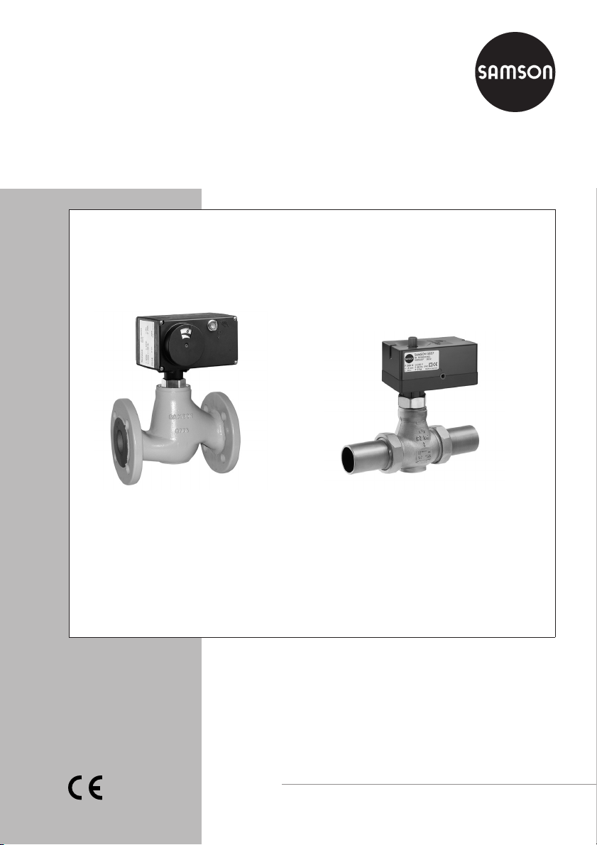
Electric Control Valves/
Controller with Electric Actuator
Type 3222/5724, Type 3222/5725 and Type 3222/5757
Type 3222/5725 Globe Valve mounted on
Controller with Electric Actuator
Type 3222/5757 Globe Valve mounted on
Controller with Electric Actuator
Mounting and
Operating Instructions
EB 5766 EN
Edition July 2008
Page 2

Contents
Contents Page
1 Design and principle of operation . . . . . . . . . . . . . . . . . . . 4
1.1 Versions . . . . . . . . . . . . . . . . . . . . . . . . . . . . . . . . 4
1.2 Technical data . . . . . . . . . . . . . . . . . . . . . . . . . . . . . 6
2 Installation . . . . . . . . . . . . . . . . . . . . . . . . . . . . . . . 9
2.1 Mounting position . . . . . . . . . . . . . . . . . . . . . . . . . . . 9
2.2 Strainer . . . . . . . . . . . . . . . . . . . . . . . . . . . . . . . . 9
2.3 Additional installation instructions . . . . . . . . . . . . . . . . . . . . 9
3 Attaching the actuator to the valve . . . . . . . . . . . . . . . . . . 10
3.1 Type 5757/-7 Controller with Electric Actuator . . . . . . . . . . . . . 10
3.2 Type 5724/5725 Controller with Electric Actuator . . . . . . . . . . . 10
4 Electrical connections . . . . . . . . . . . . . . . . . . . . . . . . . 11
4.1 Type 5757-7 Controller with Electric Actuator. . . . . . . . . . . . . . 11
4.2 Type 5757 Controller with Electric Actuator. . . . . . . . . . . . . . . 11
4.3 Type 5724/5725 Controller with Electric Actuator . . . . . . . . . . . 12
5 Manual override . . . . . . . . . . . . . . . . . . . . . . . . . . . 13
5.1 Type 5757/-7 Controller with Electric Actuator . . . . . . . . . . . . . 13
5.2 Type 5724/5725 Controller with Electric Actuator . . . . . . . . . . . 13
6 Operation . . . . . . . . . . . . . . . . . . . . . . . . . . . . . . 14
7 Maintenance . . . . . . . . . . . . . . . . . . . . . . . . . . . . . 15
8 Dimensions in mm and weights . . . . . . . . . . . . . . . . . . . . 16
9 Appendix. . . . . . . . . . . . . . . . . . . . . . . . . . . . . . . 18
9.1 Wiring for Type 5757-7 . . . . . . . . . . . . . . . . . . . . . . . . 18
9.2 Wiring for Type 5757 . . . . . . . . . . . . . . . . . . . . . . . . . 20
9.3 Wiring for Type 5724/5725 . . . . . . . . . . . . . . . . . . . . . 22
2 EB 5766 EN
Typetest
The Type 5725 Controller with Electric Actuators with safety function used in
conjunction with Type 3222 Valves are typetested according to DIN 32730
by the German technical inspectorate TÜV.
Register number available on request.
Page 3

General safety instructions
General safety instructions
The control valves may only be mounted, started up or serviced by fully
4
trained and qualified personnel, observing the accepted industry codes and
practices. Make sure employees or third persons are not exposed to any
danger.
All safety instructions and warnings in these mounting and operating
instructions, particularly those concerning assembly, start-up and
maintenance, must be observed.
The control valves fulfill the requirements of the European Pressure Equip
4
ment Directive 97/23/EC. Valves with a CE marking have a declaration of
conformity which includes information about the applied conformity assess
ment procedure. The declaration of conformity is available on request.
For appropriate operation, make sure that the control valve is only used in
4
applications where the operating pressure and temperature do not exceed
the operating values which are based on the valve sizing data submitted in
the order.
The manufacturer does not assume any responsibility for damage caused by
external forces or any other external influence!
Any hazards which could be caused in the control valve by the process
medium, the operating pressure, the signal pressure or by moving parts are
to be prevented by means of the appropriate measures.
Proper shipping and appropriate storage of the control valve are assumed.
4
-
-
Caution!
For installation and maintenance, make sure the relevant section of the
4
pipeline is depressurized and, depending on the process medium, drained
as well. If necessary, allow the control valve to cool down or warm up to
reach ambient temperature prior to starting any work on the valve.
The electric actuators have been designed for use in electrical power
4
installations. For wiring and maintenance, you are required to observe the
relevant safety regulations.
Only use power interruption devices which are protected against
4
unintentional reconnection of the power supply.
Take special care when making adjustments on live parts. Do not remove
4
any covers!
EB 5766 EN 3
Page 4

Design and principle of operation
1 Design and principle of
operation
The control valves consist of a single-seated
Type 3222 Globe Valve and either a
Type 5757, Type 5757-7 or Type 5724
Controller with Electric Actuator or a Type
5725 Controller with Electric Actuator with
safety function.
The process medium flows through the globe
valve in the direction indicated by the arrow
on the body. The position of the valve plug
determines the flow rate over the cross-sec
tional area of flow released between the
plug (3) and valve seat (2). The plug stem
(4) with plug is connected with the stem of
the actuator (10) by a force-locking connection. The valve is opened by the valve spring
(5) following the retracting movement of the
actuator stem. A special version is required
for water above 150 °C and for steam
(Fig. 1). The plug is moved by a change in
the control signal acting on the actuator.
The electric actuator with safety function
(Type 5725) has a spring mechanism and
an electromagnet that can be connected to a
safety control circuit. When the control cir
cuit is interrupted or the power supply fails,
the magnet disengages the gear from the
self-locking motor and releases the spring
mechanism. The valve is closed in the event
of a safety situation (fail-safe action
“actuator stem extends”).
The electric actuators contain a digital con
troller integrated into the actuator. The con
trolled variable is recorded over the directly
connected Pt 1000 sensor (see Table 2).
The output signal of the digital controller
acts as a three-point stepping signal on the
-
-
-
synchronous motor of the actuator and is
transferred over the connected gear as a
positioning force onto the actuator stem.
The Type 5757, Type 5724 and Type 5725
are particularly suitable for DHW heating in
instantaneous heating systems and for fixed
set point control circuits in mechanical engi
neering applications.
Type 5757-7 is suitable for heating applica
tions.
1.1 Versions
PN DN EB
Electric control valve/Controller with electric
actuator
Type 3222/5757
Type 3222/5757-7
Type 3222/5724
… with safety function
Type 3222/5725
1)
Refer to the listed Mounting and Operating
Instructions (EB) for details on the controllers
with electric actuators
2)
Controller with electric actuator for domestic
hot water heating in instantaneous heating
systems and for fixed set point control circuits
in mechanical engineering applications
3)
Controller with electric actuator for heating
applications
-
2)
25 15 to 25 5757
3)
25 15 to 25 5757-7
2)
25 15 to 50 5724
2)
25 15 to 50 5724
-
-
1)
4 EB 5766 EN
Page 5
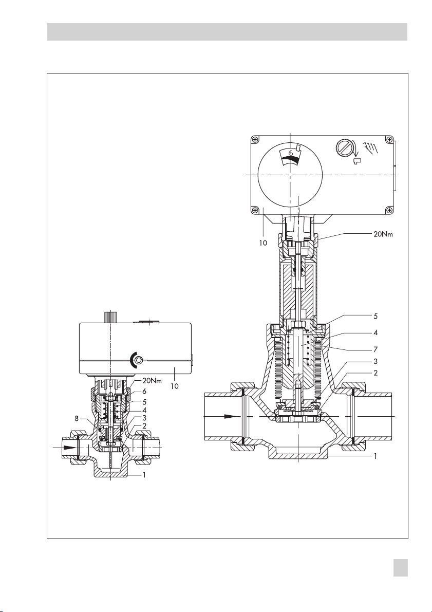
1 Valve body
2 Seat
3 Plug
4 Plug stem
5 Valve spring
6 Guide nipple
7 Balancing bellows
8 Balancing piston
10 Controller with electric
actuator
Design and principle of operation
Type 3222/5757
Fig. 1 · Type 3222/5757 and Type 3222/5724 Electric Control Valves/Controller with Electric Actuator
Special version for temperatures up to 200 °C and
Type 3222/5724
with plug balanced by a bellows
EB 5766 EN 5
Page 6

Design and principle of operation
1.2 Technical data
1. Single-seated Type 3222 Globe Valve
Nominal size DN 15 20 25 32 40 50
Version with threaded ends
Thread size G ½¾1 –––
Version with female thread • • • – – –
Nominal pressure PN 25
Seat/plug sealing Metal sealing for K
Rated travel mm 6 12
Rangeability 50 : 1
Leakage class acc. to DIN EN 1349 Class I (< 0.05 % of K
Version for water, oil and other liquids
Max. permissible temperature 150 °C
Max. permissible differential pressureΔp in bar
Types 5724 and 5725 20 12
Type 5757 20 –
Version for water and steam
Max. permissible temperature 200 °C
Max. permissible differential pressureΔp in bar
Types 5724 and 5725 20 · 10 for 3.6≤K
Type 5757 20
Materials
Valve body Red brass CC491K · EN-JS1049 (flanged body)
Seat Stainless steel 1.4104
Plug 1.4104/CW509L with soft sealing · 1.4104 for 0.1≤K
Valve spring Stainless steel 1.4310 K
Packing EPDM/FPM (FKM) · Oil-resistant version: FPM
Welding ends St 37
Threaded ends Red brass CC491K
Screwed-on flanges St 37.2
with flanges
as flanged body
••••••
2.5 · Soft sealing for K
≤
VS
coefficient)
VS
1, 2)
88
≤
3)
4)
· 5
VS
5–
3.6
≥
VS
2.5
≤
VS
6 EB 5766 EN
Page 7

Design and principle of operation
Nominal size DN 15 20 25 32 40 50
Thread size G ½¾1–––
coefficients
K
VS
Version with female thread 3.6 5.7 7.2 – – –
Version with male thread 4 6.3 8 16 20 25
Reduced K
coefficients
VS
0.1· 0.16 · 0.25 · 0.4
0.63 · 1.0 · 1.6 · 2.5
Rated travel mm 6 12
1)
Use an intermediate insulating piece for temperatures above 130 °C to protect the actuator
2)
DN 15 to 25 with Type 5757 Actuator:
Use an intermediate insulating piece for temperatures above 110 °C to protect the actuator
3)
Differential pressure for KVS= 1 and 1.6
4)
Differential pressure for KVS= 2.5 and 4
5)
Version with male thread
6)
Version with female thread
1.0 · 1.6 · 2.5
5)
6)
· 3.6
4
–––
EB 5766 EN 7
Page 8

Design and principle of operation
2. Controllers with electric actuators
Type
Nominal size DN 15 to 25 15 to 25 15 to 25 32 to 50 15 to 25 32 to 50
Scope of application Heating
Safety function Without Without With
Rated travel mm 6 6 6 12 12 6 6 12 12
Transit time for rated travel s 20 35 18 70 35 35 18 70 35
Transit time upon fail-safe
action
s – – 4466
Fail-safe action – – Stem extends
Nominal thrust kN 0.3 0.7 0.5
Manual override Yes Yes Possible
Power supply 230 V (±10 %), 50 Hz
Power consumption approx. VA 3 3 37375959
Permissible temperatures
Ambient °C 0 to 50 0 to 50 0 to 50
Storage °C –20 to 70 –20 to 70 –20 to 70
At connecting rod °C 0 to 110 0 to130 0 to 130
Degree of protection IP 42 IP 54 (upright position, acc. to DIN IEC 529)
Inputs and outputs of the digital controller
Temperature sensor Pt 1000 3 x 1 x 1 x 1 x
Setting range °C 1 to 150 0 to 150 1 to 150 1 to 150
Potentiometer input
1100/2000
Water flowmeter input – 530 pulses/l 530 pulses/l 530 pulses/l
Current input – 4 (0) to20 mA 4 (0) to 20 mA 4 (0) to 20 mA
Binary input BE1
Binary input BE2
2)
2)
Op. mode
switchover
230 V/50 Hz
Binary output BA
Cir. pump/Ex
ternal demand
1)
Manual override using a 4 mm hex screwdriver (after removing the housing cover);
always returns to fail-safe position after safety release.
2)
Recommendation for Type 5724, Type 5725 and Type 5757: With gold contacts
5757 5724 5725
5757-7 5757 -10 -13 -20 -23 -10 -13 -20 -23
DHW heating in instantaneous heating systems,
fixed set point control circuits in mechanical engineering
1)
1000 to
Ω
–– –
Switching between internal set points/
Deactivation of function to maintain temperature constant
– Flow switch
-
–– –
8 EB 5766 EN
Page 9

2 Installation
Caution!
Versions designed to handle temperatures
up to 200 °C must be fitted with the dark
gray graphite supplied with the valve. Do
not use the UDP seals available as accesso
ries as they are only suitable for tempera
tures up to 150 °C.
-
Installation
Install a strainer (SAMSON Type 2 NI)
4
upstream of the control valve to prevent
any sealing parts, weld spatter or other
foreign matter carried along by the pro
cess medium from impairing the proper
functioning of the valve, in particular, the
-
tight shut-off.
The valve must be installed free of stress.
4
If necessary, support the piping near the
connections.
-
2.1 Mounting position
Choose the place of installation where
4
the ambient temperature does not ex
ceed or fall below the permissible limits
specified for the actuator and that allows
you to freely access the control valve
even after the entire plant has been completed.
Flush the pipeline thoroughly before in-
4
stallation.
Do not install the valve with the actuator
4
suspended downwards.
Install versions for water and steam up to
200 °C with the actuator installed up
right in a horizontal pipeline.
If you wish to insulate the control valve,
4
install an intermediate insulating piece
between valve and actuator. Make sure
the insulation ends 25 mm above the
valve body. Do not insulate the actuator
and coupling nut as well.
2.2 Strainer
Install the strainer with the filter element
4
-
facing downwards upstream of the valve
inlet.
Choose the place of installation to allow
4
enough space to remove the filter.
Install the strainer with the direction of
4
flow as indicated by the arrow on the
body.
2.3 Additional installation
instructions
-
We recommend to install a hand-operated
shut-off valve both upstream of the strainer
and downstream of the control valve to be
able to shut down the plant for cleaning and
maintenance, and when the plant is not
used for longer periods of time.
EB 5766 EN 9
Page 10

Attaching the actuator to the valve
3 Attaching the actuator to the
valve
If the actuator has not already been
mounted on the valve by the manufacturer
or when the original actuator on a valve is
to be replaced with a controller with electric
actuator, proceed as follows.
Note!
Fasten the actuator and valve together either
at the valve connection or at the intermedi
ate insulating piece, depending on the valve
version, with a tightening torque of 20 Nm.
-
3.1 Type 5757/-7 Controller
with Electric Actuator
1. Turn the handwheel (see section 5.1)
counterclockwise when the actuator is
disconnected from the power supply to
retract the actuator stem as far as it will
go.
2. Place the actuator on the connection
piece and secure with the coupling nut.
3.2 Type 5724/5725 Controller
with Electric Actuator
Type 5724
1. Turn the handwheel (see section 5.2)
counterclockwise to retract the actuator
stem as far as it will go.
2. Place the actuator on the connection
piece and secure with the coupling nut.
Type 5725 with fail-safe action “Actuator
stem extends”
1. Unfasten the front cover and place a
4 mm hex screwdriver on the actuator
stem (see section 5.2).
2. Turn the screwdriver counterclockwise
only and only until the travel final value
is reached at the maximum, which activates the bottom torque switch.
Caution!
Turning the actuator too far will destroy
it.
10 EB 5766 EN
3. Hold the screwdriver in place. Secure the
actuator and connection piece with the
coupling nut.
4. Remove screwdriver and carefully
refasten the front cover.
Page 11

Electrical connections
4 Electrical connections
Upon installing the electrical cables,
you are required to observe the regula
tions concerning electrical power in
stallations according to DIN VDE 0100
as well as the regulations of your local
power supplier.
Use a suitable power supply to ensure
that no dangerous voltages from the
system or parts of the system reach the
device in standard operation or in case
of a fault.
Warning!
Only connect the device to the main
power network when the power is
switched off. Make sure the power
cannot be switched on unintentionally!
Perform the electrical wiring as required
4
depending on the application (refer to
section 4.1 to 4.3).
As soon as the actuator is connected to the
power supply, the initialization procedure
starts:
The actuator stem extends and the red and
yellow LEDs located under the cover on top
of the actuator light up. As soon as the actu
ator stem has reached the final position, the
red LED is turned off. The yellow LED re
mains illuminated and indicates that the
controller with electric actuator is ready for
operation.
4.1 Type 5757-7 Controller with
Electric Actuator
Heating application: The controller with
-
electric actuator requires a Pt 1000 temper
-
ature sensor to be connected to measure the
flow temperature. Depending on the control
task, an outdoor sensor or a room sensor or
a room panel can be connected. Combining
one of these sensors with a return flow sen
sor is usually possible. Additionally, the con
troller with electric actuator has a potenti
ometer input 1000 to 1100/2000Ω. The
non-floating pump output can alternatively
be used as an binary output for an external
request for heat demand.
The default setting (WE) is configured for an
application with a flow sensor, outdoor sensor and return flow sensor as well as with
an active binary input to switchover the operating modes (see Fig. 2).
-
-
-
-
4.2 Type 5757 Controller with
Electric Actuator
Domestic hot water heating in instanta
neous heating system: The controller with
electric actuator requires a Pt 1000 temper
ature sensor to be connected for it to func
-
tion. Two set points W1 and W2 can be
used for control. A binary input BE1 is used
-
to switch between them.
In addition, a water flowmeter or a flow
switch can be connected to quickly recog
nize when hot water is being tapped.
The 0(4) to 20 mA current input can be used
in place of the Pt 1000 sensor for control
purposes.
-
-
-
-
EB 5766 EN 11
Page 12

Electrical connections
The default setting (WE) is configured for an
application with a Pt 1000 flow temperature
sensor and water flowmeter (see Fig. 3).
4.3 Type 5724/5725 Controller
with Electric Actuator
Domestic hot water heating in instanta
neous heating system: The electric wiring
options are the same as for the Type 5757
Controller with Electric Actuator, (see
section 4.2). In addition, the pump control
output can be configured as a fault alarm
output.
The default setting (WE) is configured for an
application of the electric actuator with a
Pt 1000 flow temperature sensor, water
flowmeter and pump control output (see
Fig. 4).
-
VS
Pt 1000
or ye rd br blk gr br bl blk
Fig. 2 · Wiring of Type 5757-7 (default)
blk black
bl blue
br brown
Pt 1000
ASRüS
Pt 1000
Pt 1000
34 6521LL´N
* Caution! Live wires!
gr green
or orange
1)
230 V, 50 Hz
rd red
ye yellow
230V, 50Hz
*
Note!
Refer to the appendix of these instructions
for other possible circuits with the necessary
configuration settings or refer to the Mount
ing and Operating Instructions
EB 5757-7 EN, EB 5757 EN and
EB 5724 EN of the corresponding controller
with electric actuator.
12 EB 5766 EN
5V GND L N
or ye rd br gr blk
-
Fig. 3 · Wiring of Type 5757 (default)
1)
Water flowmeter
3)
Pump control output or fault alarm output
4)
Electromagnet, Type 5725 only
3)
230V, 50Hz
LL1 N 5V INS1 S2
4)
Fig. 4 · Wiring of Type 5724/5725 (default)
Pt 1000
1)
S1
Page 13

Manual override
5 Manual override
The direction of action and travel can be
read off the travel indication scale.
5.1 Type 5757/-7 Controller
with Electric Actuator
Caution!
Only activate the handwheel when the actu
ator is disconnected from the power supply.
Turn handwheel clockwise to extend the
4
actuator stem
Turn handwheel counterclockwise to
4
retract the actuator stem
5.2 Type 5724/5725 Controller
with Electric Actuator
Type 5724
Adjust the travel by turning the handwheel
(approx. 4 turns for 1 mm travel):
Turn clockwise to extend the actuator
4
stem
Turn counterclockwise to retract the
4
actuator stem
Type 5725
Caution!
The actuator is live!
1. Undo the front cover and place a 4 mm
hex screwdriver onto the red actuating
shaft.
2. Turn the screwdriver counterclockwise
-
only, and only until the travel final value
is reached at the maximum, which acti
vates the bottom torque switch (switching
off the motor).
Caution!
Turning the actuator too far will destroy
it.
After the fail-safe action has been triggered by the magnet, the spring mechanism pushes the actuator stem out and the
valve always move to its fail-safe position.
3. Remove screwdriver and carefully
refasten the front cover.
-
Handwheel
Travel indication
Fig. 5 · Manual override of Type 5757/-7, Type 5724 and Type 5725 (from left to right)
Travel indication Travel indication
Handwheel
Handwheel
EB 5766 EN 13
Page 14

Operation
6 Operation
The controllers with electric actuators are
adapted to the required control task by
configuration and parameterization per
formed in TROVIS-VIEW Operator Interface:
Type 5757-7: TROVIS-VIEW
4
6661-1066
Type 5757: TROVIS-VIEW 6661-1062
4
Type 5724 and Type 5725: TROVIS-
4
VIEW 6661-1060
Note!
Instructions on how to operate the
TROVIS-VIEW Operator Interface as well as
on the function and parameter settings are
contained in the Mounting and Operating
Instructions EB 5757-7 EN, EB 5757 EN
and EB 5724 EN for the corresponding controller with electric actuator.
-
14 EB 5766 EN
Page 15

7 Maintenance
The control valve is subject to natural wear.
Depending on the conditions the valve is op
erated in, it needs to be checked at regular
intervals.
If leakage to the atmosphere occurs, remove
the valve from the pipeline and replace the
damaged parts.
Warning!
For maintenance work on the valve,
make sure the relevant section of the
pipeline is depressurized and,
depending on the process medium,
drained as well.
For high medium temperatures, allow
the section of the pipeline to cool down
before you start.
Make sure the control signal for the
actuator is switched off.
Maintenance
-
EB 5766 EN 15
Page 16

Dimensions in mm and weights
8 Dimensions in mm and weights
Nominal size DN 15 20 25 32 40 50
Thread size G ½¾1 –––
Pipe Ød 21.3 26.8 33.7 42 48 60
Threadsize RG ¾ G 1G1¼G1¾G 2G2½
Width across flats SW 30 36 46 59 65 82
Length L 65 70 75 100 110 130
Length with welding ends L1 210 234 244 268 294 330
Height H2 45.5 94
Versions for temperatures up to 200 °C
and with intermediate insulating piece
Height H3 30 55
Weight without actuator approx. kg 1.4 1.8 2.3 4.0 4.4 6.8
Versions for temperatures up to 200 °C
and with intermediate insulating piece
Version with threaded ends (male thread)
Length L2 129 144 159 180 196 228
Male thread A G ½ G ¾ G 1 G1¼ G 1½ G 2
Weight without actuator approx. kg 1.4 1.8 2.3 4.0 4.4 6.8
Versions for temperatures up to 200 °C
and with intermediate insulating piece
Version with flanges
Length L3 130 150 160 180 200 230
Weight without actuator approx. kg 2.5 3.4 4.1 6.9 7.7 10.7
Versions for temperatures up to 200 °C
and with intermediate insulating piece
Version with female thread
Length L4 65 75 90 –
Female thread G G ½ G ¾ G 1 –
Weight without actuator approx. kg 1.2 1.4 1.5 –
Versions for temperatures up to 200 °C
and with intermediate insulating piece
Version with flanged valve body
Height H2 45.5 94
Length L3 130 150 160 180 200 230
Weight without actuator approx. kg 2.5 3.4 4.1 6.9 8.4 11.6
Versions for temperatures up to 200 °C
and with intermediate insulating piece
1.9 2.3 2.8 4.5 4.9 7.3
1.9 2.3 2.8 4.5 4.9 7.3
3.0 3.9 4.6 7.4 8.2 11.2
1.7 1.9 2.0 –
3.0 3.9 4.6 7.4 8.9 12.1
140 185
16 EB 5766 EN
Page 17

Dimensions in mm and weights
Weights of controllers with electric actuators
Type 5757/-7 5724 5725
Weight without valve, approx. kg 0.7 1.1 1.3
Intermediate
insulating piece
Type 3222/5757(-7),
only up to DN 25
Types 3222/5724
Types 3222/5725
Version with
flanges
Version with
threaded ends
Fig. 6 · Top: Valve dimensions (version with welding ends) · Bottom: Other valve versions
Flanged valve
body version
Version with
female thread
EB 5766 EN 17
Page 18

Appendix
9 Appendix
9.1 Wiring for Type 5757-7 (refer to EB 5757-7 EN)
Note! The pump output L´ is non-floating (230 V~).
Note: Terminals at point of installation, not included in scope of delivery
blk black · bl blue · br brown · gr green · or orange · rd red · ye yellow
Application with flow, return flow, and outdoor
sensors as well as binary input to switch between
operating modes = Default setting (WE)
Functions WE Configuration
Control w. reference variable 1 F01 - 1
Outdoor sensor 0 F02 - 0
Potentiometer/binary input 0 F05 - 0
BA as pump control output 0 F09 - 0
Return flow sensor 1 F11 - 1
VS
Pt 1000
or ye rd br blk gr br bl blk
ASRüS
Pt 1000
Pt 1000
34 6521LL´N
230 V, 50 Hz
Application with flow sensor and outdoor sensor
Functions WE Configuration
Control w. reference variable 1 F01 - 1
Outdoor sensor 0 F02 - 0
BA as pump control output 0 F09 - 0
Diagram abbreviations:
VS Flow sensor · RüS Return flow sensor · AS Outdoor sensor
18 EB 5766 EN
VS
Pt 1000
or ye rd br blk gr br bl blk
AS
Pt 1000
34 6521LL´N
230 V, 50 Hz
Page 19

Application with flow, return flow, and outdoor
sensors as well as a potentiometer for adjusting the set
points
Functions WE Configuration
Control w. reference variable 1 F01 - 1
Outdoor sensor 0 F02 - 0
Potentiometer/binary input 0 F05 - 1
Remote adjuster 0 F06 - 1
BA as pump control output 0 F09 - 0
Return flow sensor 1 F11 - 1
Application with flow, return flow, and room sensors
with operating mode switchover and set point adjuster
Functions WE Configuration
Control w. reference variable 1 F01 - 1
Room sensor 0 F02 - 1
Potentiometer/binary input 0 F05 - 1
Type 5257-7 Room Panel 0 F06 - 0
BA as pump control output 0 F09 - 0
Return flow sensor 1 F11 - 1
Appendix
VS
Pt 1000
or ye rd br blk gr br bl blk
VS
Pt 1000
or ye rd br blk gn br bl blk
ASRüS
Pt 1000
RüS
Pt 1000
21LL´N
Pt 1000
34 6521LL´N
Type 5257-7
Room Panel
1432
34 65
100/
1000 Ω
1000 Ω
230 V, 50 Hz
230 V, 50 Hz
EB 5766 EN 19
Page 20

Appendix
9.2 Wiring for Type 5757 (refer to EB 5757 EN)
Note: Terminals at point of installation, not included in scope of delivery
1)
Water flowmeter
2)
Flow switch
blk black · bl blue · br brown · gr green · or orange · rd red · ye yellow
Operation with Pt 1000 sensor and water flowmeter
= Default setting (WE)
Functions WE Configuration
Hot water tapping recognition 1 F01 - 1
Water flowmeter 1 F02 - 1
Current input 0 F05 - 0
Pt 1000
or ye rd br gr blk
1)
5V GND L N
230V, 50Hz
Operation with Pt 1000 sensor
Functions WE Configuration
Hot water tapping recognition 1 F01 - 0
Current input 0 F05 - 0
Operation with Pt 1000 sensor and binary contact for
switching between set points
Functions WE Configuration
Hot water tapping recognition 1 F01 - 0
Current input 0 F05 - 0
Binary input function 0 F08 - 1
20 EB 5766 EN
Pt 1000
5V GND L N
or ye rd br gr blk
Pt 1000
BE1
5V GND L N
or ye rd br gr blk
230V, 50Hz
230V, 50Hz
Page 21

Operation with Pt 1000 sensor and flow switch
Functions WE Configuration
Hot water tapping recognition 1 F01 - 1
Flow switch 1 F02 - 0
Current input 0 F05 - 0
Operation with Pt 1000 sensor and external set point
over an mA signal
Functions WE Configuration
Hot water tapping recognition 1 F01 - 0
Current input 0 F05 - 0
Current input function 0 F06 - 1
Pt 1000
or ye rd br gr blk
+ 4(0)...20mA –
Pt 1000
or ye rd br gr blk
2)
BE2
5V GND L N
5V GND L N
Appendix
230V, 50Hz
230V, 50Hz
Operation with mA signal input
Functions WE Configuration
Hot water tapping recognition 1 F01 - 0
Current input 0 F05 - 0
Current input function 0 F06 - 0
+ 4(0)...20mA –
230V, 50Hz
5V GND L N
or ye rd br gr blk
EB 5766 EN 21
Page 22

Appendix
9.3 Wiring for Type 5724/5725 (refer to EB 5724 EN)
1)
Water flowmeter
2)
Flow switch
3)
Pump control output or fault alarm output
4)
Electromagnet, Type 5725
Domestic hot water heating in instantaneous heating system
Operation with Pt 1000 sensor und water flowmeter
= Default setting (WE)
Functions WE Configuration
Hot water tapping recognition 1 F01 - 1
Water flowmeter 1 F02 - 1
Current input 0 F05 - 0
Operation with Pt 1000 sensor
Functions WE Configuration
Hot water tapping recognition 1 F01 - 0
Current input 0 F05 - 0
3)
230V, 50Hz
LL1 N 5V INS1 S2
4)
3)
230V, 50Hz
LL1 N 5V INS1 S2
Pt 1000
Pt 1000
1)
S1
S1
Operation with Pt 1000 sensor and binary contact for
switching between set points
Functions WE Configuration
Hot water tapping recognition 1 F01 - 0
Current input 0 F05 - 0
Binary input function 0 F08 - 1
22 EB 5766 EN
4)
3)
230V, 50Hz
LL1 N 5V INS1 S2
4)
Pt 1000
BE1
S1
Page 23

Operation with Pt 1000 sensor and
flow switch
Functions WE Configuration
Hot water tapping recognition 1 F01 - 1
Flow switch 1 F02 - 0
Current input 0 F05 - 0
Mechanical engineering applications
Operation with Pt 1000 sensor and external set point
over an mA signal input
Functions WE Configuration
Hot water tapping recognition 1 F01 - 0
Current input 0 F05 - 0
Current input function 0 F06 - 1
3)
230V, 50Hz
LL1 N 5V INS1 S2
4)
3)
230V, 50Hz
LL1 N 5V INS1 S2
4)
Pt 1000
S1
+–4(0) ... 20mA
Pt 1000
S1
BE2
Appendix
2)
Operation with mA sensor input
Functions WE Configuration
Hot water tapping recognition 1 F01 - 0
Current input 0 F05 - 0
Current input function 0 F06 - 0
3)
230V, 50Hz
LL1 N 5V INS1 S1S2
4)
+–4(0) ... 20mA
EB 5766 EN 23
Page 24

SAMSON AG · MESS- UND REGELTECHNIK
Weismüllerstraße 3 · 60314 Frankfurt am Main · Germany
Phone: +49 69 4009-0 · Fax: +49 69 4009-1507
Internet: http://www.samson.de
EB 5766 EN
2008-11
 Loading...