

Page 1
Mounting and
Operating Instructions
EB 8053 EN
Edition June 2014
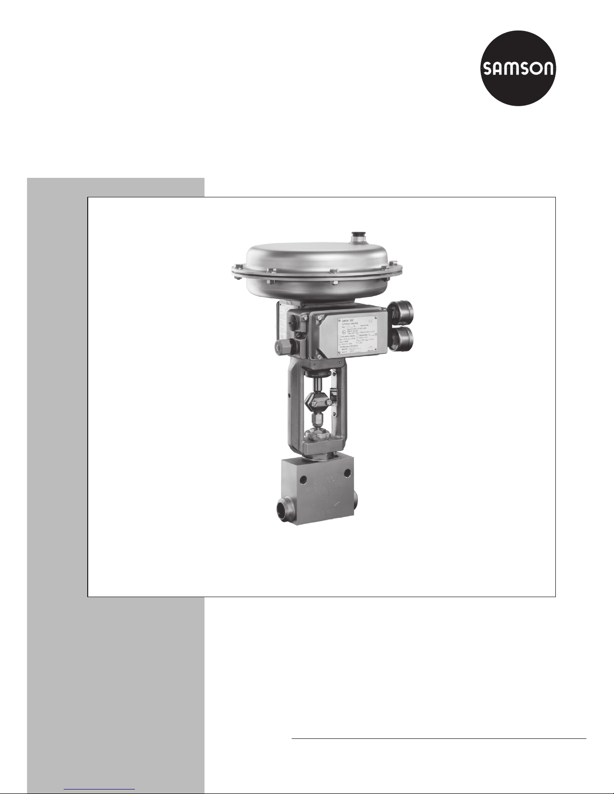
Type 3252 High-pressure valve with Type3277 Pneumatic Actuator and Type3767 Electropneumatic
Positioner
Series 250
Type3252‑1 and Type3252‑7
Pneumatic Control Valves
Page 2
Denition of signal words
DANGER!
Hazardous situations which, if not
avoided, will result in death or serious injury
WARNING!
Hazardous situations which, if not
avoided, could result in death or serious injury
NOTICE
Property damage message or malfunction
Note:
Additional information
Tip:
Recommended action
2 EB 8053 EN
Page 3

Contents
EB 8053 EN 3
1 General safety instructions .............................................................................5
2 Design and principle of operation ..................................................................6
1.1 Fail-safe position ............................................................................................6
1.2 Replacing the actuator ....................................................................................6
3 Assembling and adjusting the valve and actuator ...........................................8
1.1 Reversal of the operating direction ..................................................................9
4 Installation ....................................................................................................9
1.2 Signal pressure line ........................................................................................9
5 Troubleshooting...........................................................................................10
1.1 Removing the actuator from the valve ............................................................10
1.2 Replacing the packing in standard valves .......................................................10
1.2.1 Plug ............................................................................................................11
1.2.2 Seat ............................................................................................................11
1.1 Replacement in valve with insulating section or bellows seal ............................12
1.1.1 Packing .......................................................................................................12
1.1.2 Plug ............................................................................................................12
1.1.3 Metal bellows ..............................................................................................12
1.1.1 Reassembly .................................................................................................14
6 Appendix ....................................................................................................15
1.1 Nameplate ..................................................................................................15
1.2 Customer inquiries .......................................................................................15
Page 4

4 EB 8053 EN
Page 5

EB 8053 EN 5
General safety instructions
1 General safety instructions
For your own safety, follow these instructions concerning the mounting, start-up and operation of the valve:
− The valve is to be mounted, started up or operated only by trained and experienced per-
sonnel familiar with the product.
− According to these mounting and operating instructions, trained personnel refers to indi-
viduals who are able to judge the work they are assigned to and recognize possible dangers due to their specialized training, their knowledge and experience as well as their
knowledge of the applicable standards.
− Any hazards that could be caused in the valve by the process medium, the signal pres-
sure or by moving parts are to be prevented by taking appropriate precautions.
− To ensure appropriate use, only use the valve in applications where the operating pres-
sure and temperatures do not exceed the specications used for sizing the valve at the ordering stage.
To avoid damage to any equipment, the following also applies:
− Proper shipping and storage are assumed.
Page 6

6 EB 8053 EN
Design and principle of operation
2 Design and principle of oper-
ation
The Type 3252 Valve with a globe-style or
angle-style body can be combined with
either a Type3271 Pneumatic Actuator or a
Type3277 Pneumatic Actuator with integral
positioner attachment.
The standard valve bodies have threaded
ends with either G or NPT thread.
Special valve versions are designed with
either weld-on anges or welding ends for
welding into the pipeline.
The modular design allows the actuators to
be exchanged and an insulating section or
metal bellows to be tted to the standard
valve version
The medium ows through the valve in the
direction indicated by the arrow. The plug is
moved by changing the signal pressure acting on the diaphragm of the actuator. The
plug stem (6) is connected to the actuator
stem (8.1) by the stem connector (7).
The plug stem is sealed by a spring-loaded
V-ring packing (4.2).
2.1 Fail-safe position
Depending on how the springs are arranged
in the actuator, the control valve assumes
one of two different fail-safe positions:
Actuator stem extends (fail-close): When the
pressure is relieved from the diaphragm or
the supply air fails, the actuator springs close
the valve.
Actuator stem retracts (fail-open): When the
pressure is relieved from the diaphragm or
the supply air fails, the actuator springs
open the valve.
2.2 Replacing the actuator
A pneumatic actuator can be replaced by
another pneumatic actuator in a different
size.
If the travel range of the actuator is larger
than the travel of the valve, the springs in the
actuator are preloaded by SAMSON so that
the travel ranges match.
Page 7

EB 8053 EN 7
Design and principle of operation
1 Valve body
1.1 Gasket
2 Seat
4.1 Spring
4.2 Packing
4.3 Washer
5 Valve bonnet
5.1 Guide bushing
5.2 Threaded bushing
5.3 Yoke
5.4 Ring nut
5.5 Screw
5.6 Anti-rotation xture
5.7 Travel indicator
scale
6 Plug stem
6.1 Stem connector nut
6.2 Lock nut
7 Stem connector
8.1 Actuator stem
8.2 Ring nut
8.3 Springs
8.4 Rolling diaphragm
9 Signal pressure con-
nection
10 Vent plug
10
9
8.4
8.3
8.2
8.1
5.3
5.7
7
6.1
6.2
5.2
5.1
2
1
5.4
4.1
1.1
5.5
5.6
5
4.2
4.3
6
9
Fig.1: Sectional drawing of Type3252 Valve with Type3271 Actuator (120cm²)
Page 8

8 EB 8053 EN
Assembling and adjusting the valve and actuator
3 Assembling and adjusting the
valve and actuator
Proceed as follows if the original actuator is
to be replaced by an actuator of another
type or size:
1. Loosen the lock nut(6.2) and stem connector nut(6.1) on the valve.
2. Press the plug together with the plug stem
rmly into the seat. Thread down the lock
nut and stem connector nut.
3. Remove the clamps of the stem connector
(7) and the ring nut (8.2) from the actuator. Slide the ring nut over the plug stem.
4. Place the actuator onto the yoke(5.3)
and secure it with the ring nut(8.2).
5. Read the bench range or (signal pressure
range with preloaded springs) and operating direction of the actuator specied
on the actuator nameplate.
Note:
The fail-safe action "actuator stem
extends" or "actuator stem retracts"
is marked by FA or FE on the
Type3271 Actuator, and by a corresponding symbol on the nameplate
of the Type3277 Actuator.
The lower value corresponds to the
lower bench range value to be adjusted, whereas the upper value corresponds the upper bench range val-
ue.
6. For fail-close actuators, apply a signal
pressure that corresponds to the lower
bench range value (e.g. 0.6bar for a
range between 0.6 and 1bar) to the signal pressure connection on the bottom
diaphragm chamber.
For fail-open actuators, apply a signal
pressure that corresponds to the upper
bench range value (e.g. 0.6bar for a
range between 0.2 and 0.6bar) to the
signal pressure connection on the top diaphragm chamber.
7. Screw on the stem connector nut(6.1) by
hand until it touches the actuator stem
(8.1). Then turn it a further ¼turn and
secure this position with the lock nut(6.2)
8. Position clamps of the stem connector (7)
and screw them tight. Align the travel indicator(5.7) with the tip of the stem connector.
The following applies to removing the actuator:
Î Apply a signal pressure that is slightly
higher than the lower bench range value
(see actuator nameplate) to the signal
pressure connection.
Note:
Actuators with preloaded springs are
labeled correspondingly and can al-
so be identied by three long bolts
protruding from the bottom of the ac-
tuator.
Page 9

EB 8053 EN 9
Installation
3.1 Reversal of the operating
direction
The operating direction and fail-safe action
of pneumatic actuators can be changed. Refer to the mounting and operating instructions of the actuator for details on how to
proceed:
− Types 3271 and 3277 Actuator
(120cm²):
u EB 8310-1EN
− Types 3271 and 3277 Actuator (350
and 700cm²):
u EB 8310-6EN
4 Installation
The following applies concerning the installation of the valve:
Î The valve can be mounted in any desired
position. The ow of direction must correspond with the direction indicated by
the arrow on the valve body.
Î Make sure the valve is installed free of
stress. If necessary, support the pipelines
near the connections.
Î Flush the pipeline thoroughly before in-
stalling the valve (valve open).
The following points additionally apply to
the version with welding ends:
Î The valve must be welded into the pipe-
line by trained personnel observing the
applicable standards.
Î Before welding the valve into the pipe-
line, move the plug out of the seat. The
entire valve does not need to be dismantled.
Î Before start-up, make sure that the valve
is free from weld spatter and other impu-
rities.
4.1 Signal pressure line
Connect the signal pressure line for a valve
with fail-close actuator to the connection on
the bottom diaphragm case, and for a valve
with fail-open actuator to the connection on
the top diaphragm case.
In the Type3277 Actuator, the bottom signal
pressure connection is located at the side of
the yoke under the bottom diaphragm case.
Page 10

10 EB 8053 EN
Troubleshooting
5 Troubleshooting
External leakage can indicate that the packing is defective or the metal bellows is defective (in a version with a bellows seal).
If the valve does not close tightly, tight shutoff may be impaired by dirt stuck between
the seat and plug or by damaged facings.
Î In this case, remove parts, carefully clean
them and renew them, if necessary.
Î Before starting any work on the valve
body, rst remove the actuator (see section5.1).
WARNING!
Risk of injury due to process medium
escaping under pressure.
Depressurize the relevant section of
the pipeline and, if necessary, drain
it as well. When used at high temperatures, allow the plant section to
cool down to ambient temperature.
Tip:
Before performing maintenance
work, we recommend removing the
valve from the pipeline or the entire
valve construction when the valve is
welded into the pipeline.
5.1 Removing the actuator
from the valve
1. Mount the stem connector clamps (7) be-
tween the actuator stem and the plug
stem.
2. For fail-close actuators, apply a signal
pressure that is higher than the lower
bench range value (see nameplate) to the
actuator so that the ring nut (8.2) can be
unscrewed.
3. Unscrew the ring nut.
4. Disconnect the signal pressure again.
5. Remove the actuator from the valve yoke.
5.2 Replacing the packing in
standard valves
Note:
Contact your nearest SAMSON subsidiary or the SAMSON After-sales
Service department for information
on suitable lubricants.
Î See Fig.1 on page 7
If the packing leaks, replace it as follows:
1. Unscrew the ring nut (5.4) and remove
the yoke (5.3) from the valve bonnet.
2. Unscrew the lock nut(6.2) and stem con-
nector nut(6.1). Unscrew the screw (5.5)
for the anti-rotation xture. Remove the
anti-rotation xture (5.6).
3. Undo screws (5) on the valve bonnet. Re-
move the valve bonnet along with the
plug stem (6).
Page 11

EB 8053 EN 11
Troubleshooting
4. Undo the threaded bushing (5.2). Pull the
plug stem along with the plug out of the
valve bonnet.
5. Unscrew thread bushing (5.2) and push
out the packing rings (4.2), washer (4.3)
and spring (4.1) using a suitable tool.
6. Clean the packing chamber thoroughly.
7. Apply a suitable lubricant to the plug
stem and packing rings (4.2).
8. Slide the plug stem with the plug into the
valve bonnet.
Slide the spring (4.1), washer (4.3) and
new packing rings over the plug stem into the packing chamber.
9. Insert the threaded bushing (5.2) and
tighten it as far as it will go.
10. Loosely screw the lock nut(6.2) and stem
connector nut(6.1) onto the plug stem
(6).
11. Insert the new gasket (1.1) into the body.
12. Fasten the valve bonnet to the body
(tightening torque of 500Nm).
13. Place the anti-rotation xture (5.6) on the
valve bonnet ensuring that the screw
(5.5) is inserted into the long hole. Fasten tight.
14. Place the yoke(5.3) on the valve body
and secure it with the ring nut (5.4).
15. Mount the actuator and adjust the upper
and lower bench range values (see section3).
Tip:
When replacing the seat and plug,
we also recommend replacing the
packing (4.2).
5.2.1 Plug
Î Proceed as described in section5.2.
Replace the old plug with a new plug
with plug stem.
Î Apply a suitable lubricant to the plug
stem before insertion.
5.2.2 Seat
Î Proceed as described in section5.2 and
additionally unscrew the seat (2).
Î Apply a suitable lubricant to the thread
and the sealing cone of the new seat.
Screw in the seat (tightening torque of
180Nm).
Alternatively, an old seat can be used after it has be machined or thoroughly
cleaned.
Page 12

12 EB 8053 EN
Troubleshooting
5.3 Replacement in valve with
insulating section or bellows seal
5.3.1 Packing
1. Unscrew the ring nut (5.4) and lift off the
yoke (5.3).
2. Unscrew the lock nut(6.2) and stem con-
nector nut(6.1). Undo the threaded
bushing (5.2).
3. Unscrew the screw (16). Remove the
anti-rotation xture (5.6).
4. Undo screws (5) on the valve bonnet. Lift
the valve bonnet over the plug stem extension (12).
5. Replace packing as described in sec-
tion5.2.
5.3.2 Plug
1. Unscrew the ring nut (5.4) and lift off the
yoke (5.3).
2. Unscrew the screw (5.5). Remove the
anti-rotation xture (5.6).
3. Undo screws (5) on the valve bonnet. Lift
the valve bonnet along with the intermediate piece (11) of the bellows seal or insulating section off the valve body.
Î To unscrew the plug stem (6) from the
plug stem extension (12), screw the stem
connector nut (6.1) and lock nut (6.2)
until they lock each other. Place a wrench
on the nuts to allow the plug stem extension to be held stationary.
Î Make sure that absolutely no torque is
transferred to the bellows which is attached to the intermediate piece.
4. Apply a suitable lubricant to the the plug
stem (6) of the old machined or new
plug.
5. Check whether the two washers (12.1)
are still in the plug stem extension (12).
Screw the plug stem tightly into the plug
stem extension (tightening torque of
50Nm).
5.3.3 Metal bellows
1. Unscrew the plug stem (6) along with
plug out of the plug stem extension (12)
as described in section5.3.2.
2. Unscrew the nut (14) using a SAMSON
socket wrench (order no. 93252-0000-
085).
3. Pull the bellows seal (13) with the plug
stem extension welded to it out of the intermediate piece (11).
4. Clean the sealing faces on the intermediate piece.
5. Slide the new bellows seal into the intermediate piece and fasten with nut (14)
(tightening torques: up to PN 160 =
85Nm, up to PN 400 on request).
6. Check whether the two washers (12.1)
are still in the plug stem extension.
7. Apply a suitable lubricant to the thread
of the plug stem and screw the plug stem
tightly into the plug stem extension (12)
(tightening torque of 50Nm).
Page 13

EB 8053 EN 13
Troubleshooting
5.3
5.2
6.1
6.2
5.4
5
16
15
11.1
14
13
12
12.1
6
5.5
5.6
1.1
11
Version
with
insulating
section
Version with
bellows seal
1.1 Gasket
5 Valve bonnet
5.2 Threaded bushing
5.3 Yoke
5.4 Ring nut
5.5 Screw
5.6 Anti-rotation xture
6 Plug stem
6.1 Stem connector nut
6.2 Lock nut
11 Intermediate piece
11.1 Gasket
12 Plug stem extension
12.1 Washers
13 Bellows seal
14 Nut
15 Anti-rotation xture
16 Screw
Fig.2: Version with insulating section or bellows seal
Page 14

14 EB 8053 EN
Troubleshooting
5.3.4 Reassembly
1. After exchanging the plug, seat and metal bellows, renew the gaskets (1.1 and
11.1) on the intermediate piece (11).
2. Fasten the intermediate piece (11) to the
valve body (tightening torque of
500Nm).
3. Place the anti-rotation xture (5.6) on the
valve body ensuring that the screw (5.5)
is inserted into the long hole. Fasten
tight.
4. Place the valve bonnet (5) over the plug
stem extension onto the intermediate
piece (12) and fasten it in the intermediate piece (tightening torque of 120Nm).
5. Place the anti-rotation xture (15) on the
valve bonnet ensuring that the screw (16)
is inserted into the long hole. Fasten
tight.
6. Reapply a suitable lubricant to the plug
stem and packing rings.
Slide the spring (4.1), washer (4.3) and
packing rings (4.2) over the plug stem
into the packing chamber.
7. Insert the threaded bushing (5.2) and
tighten it as far as it will go.
8. Loosely screw the lock nut(6.2) and stem
connector nut(6.1) onto the plug stem
extension (12).
9. Place the yoke onto the valve bonnet and
secure it with the ring nut (5.4).
10. Mount the actuator and adjust the upper
and lower bench range values as described in section3.
Page 15

EB 8053 EN 15
Appendix
6 Appendix
6.1 Nameplate
SAMSON
12
DN
PN
CI
K
vs
C
v
33–
78
6
1 Type designation
2 Nominal size
3 Order no. with modication index
6 Material
7 Nominal pressure
8 K
VS/CV
coefcient
Fig.3: Nameplate for valve
SAMSON
1
6
57
VFH
234
1 Type designation
2 Modication index
3 Actuator area
4 Fail-safe action:
FA Actuator stem extends
FE Actuator stem retracts
5 Actuator travel
6 Bench range
7 Bench range with preloaded springs
Fig.4: Nameplate for Type 3271 Actuator
6.2 Customer inquiries
Please submit the following details:
− Type designation and order number
(stamped on the nameplate)
− Version and nominal size of the valve
− Pressure and temperature of the process
medium
− Flow rate in m³/h
− Bench range of the actuator
− Installation drawing
Page 16

SAMSON AG · MESS- UND REGELTECHNIK
Weismüllerstraße 3 · 60314 Frankfurt am Main, Germany
Phone: +49 69 4009-0 · Fax: +49 69 4009-1507
samson@samson.de · www.samson.de
EB 8053 EN
2014-10-20 · English
 Loading...