

Page 1
Mounting and
Operating Instructions
EB 3136 EN
Translation of original instructions
Edition December 2017
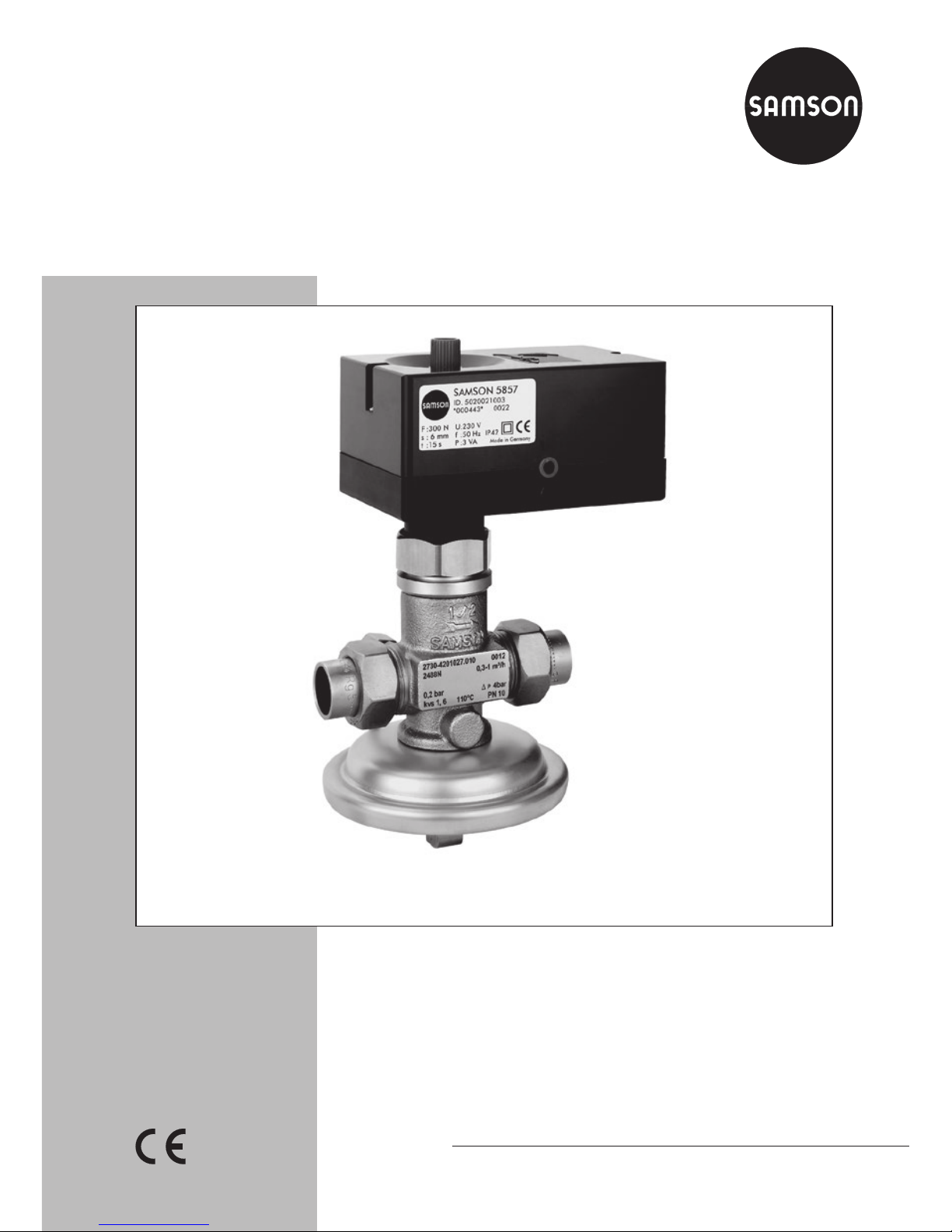
Type2488N/5857
Pressure-independent Control Valve (PICV)
Type2488N/5857
Page 2
2 EB 3136 EN
Note on these mounting and operating instructions
These mounting and operating instructions assist you in mounting and operating the device
safely. The instructions are binding for handling SAMSON devices.
Î For the safe and proper use of these instructions, read them carefully and keep them for
later reference.
Î If you have any questions about these instructions, contact SAMSON‘s After-sales Service
Department (aftersalesservice@samson.de).
The mounting and operating instructions for the devices are included in
the scope of delivery. The latest documentation is available on our website
(www.samson.de) > Product documentation. You can enter the document
number or type number in the [Find:] eld to look for a document.
Denition of signal words
Hazardous situations which, if not avoided,
will result in death or serious injury
Hazardous situations which, if not avoided,
could result in death or serious injury
Property damage message or malfunction
Additional information
Recommended action
DANGER
!
WARNING
!
NOTICE
!
Note
Tip
Page 3

Contents
EB 3136 EN 3
1 Safety instructions and measures ...................................................................4
1.1 Notes on possible severe personal injury .........................................................6
1.2 Notes on possible personal injury ...................................................................7
1.3 Notes on possible property damage ................................................................7
2 Markings on the device .................................................................................8
2.1 Nameplate for Type2488N Valve .................................................................. 8
3 Design and principle of operation ..................................................................9
3.1 Technical data .............................................................................................10
4 Measures for preparation ............................................................................14
4.1 Unpacking ..................................................................................................14
4.2 Transporting and lifting ................................................................................14
4.3 Storage .......................................................................................................15
4.4 Preparation for installation ............................................................................16
5 Mounting and start-up .................................................................................16
5.1 Mounting position ........................................................................................16
5.2 Additional ttings .........................................................................................17
5.3 Mounting the actuator ..................................................................................17
5.4 Electrical connection .....................................................................................18
5.5 Start-up ....................................................................................................... 19
6 Operation ...................................................................................................20
6.1 Adjusting the set points .................................................................................20
6.1.1 Flow rate .....................................................................................................20
7 Servicing.....................................................................................................21
7.1 Preparation for return shipment .....................................................................22
7.2 Ordering spare parts and operating supplies .................................................23
8 Malfunctions ...............................................................................................23
8.1 Decommissioning .........................................................................................24
8.2 Disposal ......................................................................................................24
9 Appendix ....................................................................................................24
9.1 After-sales service ........................................................................................24
9.2 Certicates ..................................................................................................25
Page 4

4 EB 3136 EN
Safety instructions and measures
1 Safety instructions and measures
Intended use
The Type2488N/5857 Pressure-independent Control Valve (PICV) is intended for ow control of liquids up to 110°C. The Type2488N/5857 is mainly used in district heating supply
networks. The regulator and actuator are designed to operate under exactly dened condi-
tions (e.g. operating pressure, process medium, temperature). Therefore, operators must ensure that the regulator and actuator are only used in operating conditions that meet the spec-
ications used for sizing the devices at the ordering stage. In case operators intend to use the
devices in other applications or conditions than specied, contact SAMSON.
SAMSON does not assume any liability for damage resulting from the failure to use the device for its intended purpose or for damage caused by external forces or any other external
factors.
Î Refer to the technical data and nameplate for limits and elds of application as well as
possible uses.
Reasonably foreseeable misuse
The regulator is not suitable for the following applications:
− Use outside the limits dened during sizing and by the technical data
Furthermore, the following activities do not comply with the intended use:
− Use of non-original spare parts
− Performing service and repair work not described in these instructions
Qualications of operating personnel
The regulator must be mounted, started up, serviced and repaired by fully trained and qualied personnel only; the accepted industry codes and practices are to be observed. According to these mounting and operating instructions, trained personnel refers to individuals who
are able to judge the work they are assigned to and recognize possible hazards due to their
specialized training, their knowledge and experience as well as their knowledge of the appli-
cable standards.
Page 5

EB 3136 EN 5
Safety instructions and measures
Personal protective equipment
We recommend wearing the following protective equipment depending on the process medium:
− Protective clothing, gloves and eyewear in applications with hot, cold and/or corrosive
media
− Wear hearing protection when working near the valve.
Î Check with the plant operator for details on further protective equipment.
Revisions and other modications
Revisions, conversions or other modications of the product are not authorized by
SAMSON. They are performed at the user's own risk and may lead to safety hazards, for
example. Furthermore, the product may no longer meet the requirements for its intended use.
Warning against residual hazards
To avoid personal injury or property damage, plant operators and operating personnel must
prevent hazards that could be caused in the regulator by the process medium, the operating
pressure or by moving parts by taking appropriate precautions. They must observe all haz-
ard statements, warning and caution notes in these mounting and operating instructions, especially for installation, start-up and service work.
Responsibilities of the operator
The operator is responsible for proper operation and compliance with the safety regulations.
Operators are obliged to provide these mounting and operating instructions as well as the
referenced documents to the operating personnel and to instruct them in proper operation.
Furthermore, the operator must ensure that operating personnel or third persons are not exposed to any danger.
Responsibilities of operating personnel
Operating personnel must read and understand these mounting and operating instructions
as well as the referenced documents and observe the specied hazard statements, warnings
and caution notes. Furthermore, the operating personnel must be familiar with the applicable
health, safety and accident prevention regulations and comply with them.
Page 6

6 EB 3136 EN
Safety instructions and measures
Referenced standards and regulations
The regulators comply with the requirements of the European Pressure Equipment Directive
2014/68/EU. Devices with a CE marking have an EU declaration of conformity, which includes information about the applied conformity assessment procedure. This EU declaration
of conformity is included in the Appendix of these instructions (see section9.2).
Non-electric valve versions whose bodies are not lined with an insulating material coating do
not have their own potential ignition source according to the risk assessment stipulated in
EN13463-1:2009, section5.2, even in the rare incident of an operating fault. Therefore,
such valve versions do not fall within the scope of Directive 2014/34/EU.
Î For connection to the equipotential bonding system, observe the requirements specied in
section 6.4 of EN60079-14 (VDE0165 Part 1).
Referenced documentation
The following documents apply in addition to these mounting and operating instructions:
− Mounting and operating instructions for the mounted actuator, e.g. uEB5857 for
Type5857 Actuator
1.1 Notes on possible severe personal injury
DANGER
!
Risk of bursting in pressure equipment.
Valves and pipelines are pressure equipment. Improper opening can lead to device
components bursting.
Î Before starting any work on the device, depressurize all plant sections concerned
as well as the valve.
Î Drain the process medium from all the plant sections concerned as well as the
valve.
Î If necessary, install a suitable overpressure protection in the plant section.
Î Wear personal protective equipment.
Page 7

EB 3136 EN 7
Safety instructions and measures
1.2 Notes on possible personal injury
WARNING
!
Risk of personal injury due to residual process medium in the valve.
While working on the valve, residual process medium can escape and, depending on
its properties, may lead to personal injury, e.g. (chemical) burns.
Î If possible, drain the process medium from all the plant sections concerned and the
valve.
Î Wear protective clothing, safety gloves and eyewear.
Risk of burn injuries due to hot or cold components and pipelines.
Depending on the process medium, valve components and pipelines may get very hot
or cold and cause burn injuries.
Î Allow components and pipelines to cool down or heat up.
Î Wear protective clothing and safety gloves.
1.3 Notes on possible property damage
NOTICE
!
Risk of valve damage due to contamination (e.g. solid particles) in the pipeline.
The plant operator is responsible for cleaning the pipelines in the plant.
Î Flush the pipelines before start-up.
Î Observe the maximum permissible pressure for valve and plant.
Risk of valve damage due to unsuitable medium properties.
The valve is designed for process media with dened properties.
Î Only use process media specied for sizing the valve.
Page 8
8 EB 3136 EN
Markings on the device
2 Markings on the device
2.1 Nameplate for Type2488N Valve
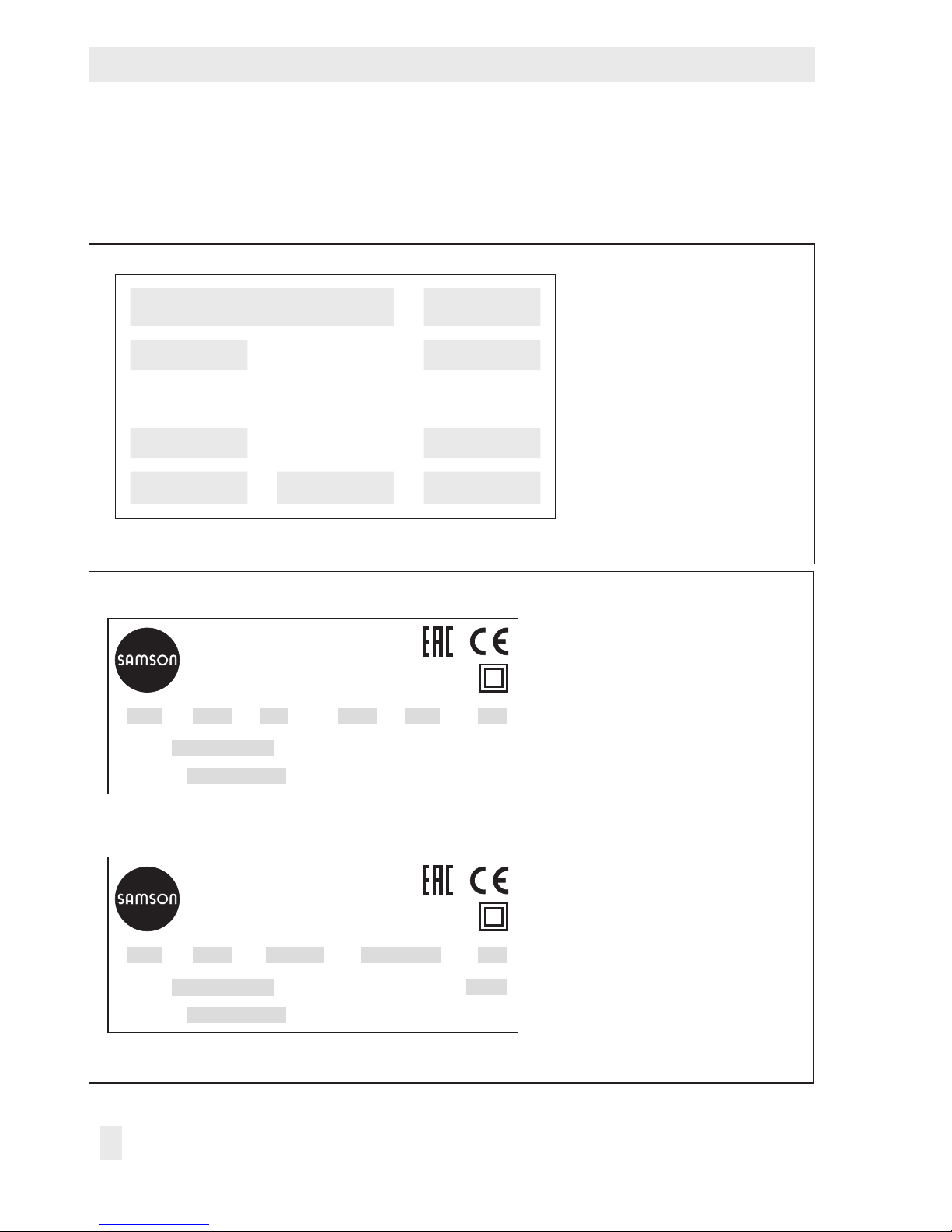
Nameplate for Type2488N Valve
1 Model number and conguration
ID
2 Order number or year of
manufacture
3 Type designation
4 Flow rate set point range in m³/h
5 Differential pressure at the
restriction in bar
6 Max. perm. differential pressure
Δp in bar
7 Flow coefcient K
VS
8 Max. permissible temperature in °C
9 Nominal pressure PN
1 2
3 4
5 6
7 8 9
Nameplate of Type5857 Actuator
1 Conguration ID
2 Serial number
3 Thrust
4 Rated travel
5 Transit time for rated travel
6 Power supply
7 Rated frequency
8 Power consumption
9 Input signal
10 Firmware version
Made in Germany
754
6
8
SAMSON 5857
Electric Actuator
s: t: f:U: P
:
Var.-ID
Serial-No.
1
2
F: 3
Made in Germany
94
6
8
SAMSON 5857
Electric Actuator
with digital positioner
s: In: U: P
:
Var.-ID
Serial-No.
1
Firmware-Version: 10
2
F: 3
Three-step version
Version with digital positioner
Fig.1: Nameplates for Type2488N Valve and Type5857 Actuator
Page 9
EB 3136 EN 9
Design and principle of operation
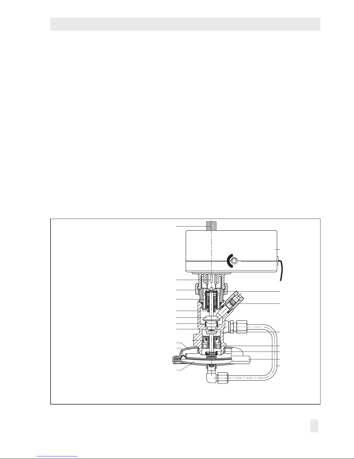
3 Design and principle of oper-
ation
Î Refer to Fig.2
The pressure-independent control valve
(PICV) consists of the Type2488N Flow
Regulator and the Type5857 Electric Actuator. The valve is tted with a connecting
piece for connection of an electric actuator.
As a result, it is possible to transmit the control signal of an electric control device to
achieve additional temperature control by
changing the restriction position. The medi-
um ows through the valve in the direction
indicated by the arrow on the valve body.
The ow rate is determined by the area re-
leased by the valve plug (3) and the adjustable restriction (11).
The installed positioning spring (5) determines the differential pressure across the re-
striction of 0.2bar. The pressure upstream of
the restriction (11) is transmitted over the
control line (7) to the upstream pressure side
of the actuator. The pressure downstream of
the restriction acts on the low-pressure side
of the operating diaphragm (9) through a
hole in the valve plug. The differential pressure generated at the restriction is converted
into a positioning force by the operating diaphragm. This force is used to move the valve
plug depending on the force of the position-
ing spring (5). The ow rate is adjusted at
the set point screw (13).
1 Valve body
2 Seat
3 Plug
4 Plug stem
5 Positioning spring
6 Diaphragm actuator
7 Control line for upstream pressure
8 Upstream side
9 Operating diaphragm
10 Downstream side
11 Restriction
12 Restriction stem
13 Set point screw for ow control
14 Connecting piece
15 Spring
16 Type5857 Electric Actuator
17 Coupling nut
(max. 20Nm tightening torque)
18 Actuator stem
19 Manual adjuster
1
11
12
17
18
2
6
7
4
5
3
14
16
13
8
9
10
15
19
Fig.2: Functional diagram
Page 10

10 EB 3136 EN
Design and principle of operation
3.1 Technical data
The regulator's nameplate contains information on the regulator version (see sec-
tion2.1).
Process medium and scope of application
The Type2488N/5857 Pressure-indepen-
dent Control Valve (PICV) is suitable for the
control of water and non-ammable gases.
− Non-ammable gases up to 80°C
− Liquids up to 110°C
The regulator is open when relieved of pressure. It closes when the downstream pressure
rises above the adjusted set point.
Compliance
The Type2488N/5857 Regulator bears
both the CE and EAC marks of conformity.
Temperature range
The Type2488N/5857 Regulator is designed for a temperature range from –10 to
+110°C (14 to 300°F).
Leakage class
All regulators have the leakage class I ac-
cording to IEC60534-4.
Noise emission
SAMSON is unable to make general statements about noise emission as it depends on
the valve version, plant facilities and process
medium. On request, SAMSON can perform
calculations according to IEC60534,
Part8-3 and Part8-4 or VDMA24422 (edition89).
Risk of hearing loss or deafness due to loud
noise.
Wear hearing protection when working near
the valve.
Dimensions and weights
Fig.3 as well as Table1 and Table2 provide
a summary of the dimensions and weights of
the Type2488N/5857 Regulator. The
lengths and heights in the dimensional draw-
ings are shown on p.13 onwards.
WARNING
!
Page 11

EB 3136 EN 11
Design and principle of operation
Table1: Technical data for Type2488N Valve
Type 2488N Valve
Valve size DN15
Nominal pressure PN 10
Max. perm. differential pressure Δp 4bar
K
VS
coefcient
Standard version 2.5
Special version 1.0
Max. permissible temperature
Treated water 110°C
Non-ammable gases 80°C
Flow rate set point range/limitation for water with a
differential pressure at the restriction of 0.2bar
Standard version 0.3 to 1.0 m³/h
Special version 0.1 to 0.5 m³/h
Differential pressure at the restriction 0.2bar
Materials
Body CC499K
Plug 1.4301 with EPDM seal
Restriction Brass, free of dezincication
Diaphragm EPDM without fabric reinforcement
Weight
Valve Approx. 1.0kg
Page 12

12 EB 3136 EN
Design and principle of operation
Table2: Technical data of Type5857 Actuator
Type5857 Actuator Version Three-step With digital positioner
Connection to valve Force-locking
Rated travel 6mm
Transit time for rated travel 20s 30/20
1)
/10s
Thrust 300N
Power supply
230V (±10%), 50Hz
24V (±10%), 50Hz
24V (±10%), 50Hz,
60Hz and DC
2)
Power consumption Approx. 3 VA 5VA
Manual override Yes
Permissible temperatures
Ambient 0 to 50°C
Storage –20 to +70°C
Medium 0 to 120°C
Degree of protection IP 42 according to EN60529
Class of protection II according to EN61140
Electromagnetic compatibility According to EN61000-6-2, EN61000-6-3 and EN61326
Compliance
·
Digital positioner –
Input signal
–
0 to 10V 1), Ri= 20kΩ
Position feedback 0 to 10V 1), RB= 1kΩ
Characteristic
Linear 1), equal percentage,
reverse equal percentage, user-
dened
Materials
Housing Plastic (PPO)
Coupling nut Brass · M32x1.5 connection
Intermediate insulating piece 1.4306, CW617N, PTFE, EPDM, FKM
Weight
Valve Approx. 0.7kg
1)
Default setting
2)
10 s applies to 24 V DC (–0 %, +10 %) for Transit time for rated travel setting.
Page 13

EB 3136 EN 13
Design and principle of operation
Ø95
114
65
~65
120
ISO 228/1-G ¾
B
~70
Ø12
55
80
11
32
70
80
Intermediate insulating
piece
SW30
210
Ø21.3
SW30
129
G½
Welding ends Threaded ends
Fig.3: Dimensional drawings
Page 14

14 EB 3136 EN
Measures for preparation
4 Measures for preparation
After receiving the shipment, proceed as follows:
1. Check the scope of delivery. Compare
the shipment received with the delivery
note.
2. Check the shipment for transportation
damage. Report any damage to
SAMSON and the forwarding agent
(refer to delivery note).
4.1 Unpacking
Do not remove the packaging until immediately before installing the valve into the pipeline.
4.2 Transporting and lifting
Due to the low service weight, lifting equipment is not required to lift and transport the
regulator (e.g. to install it into the pipeline).
Transport instructions
− Protect the device against external inu-
ences (e.g. impact).
− Do not damage the corrosion protection
(paint, surface coatings). Repair any
damage immediately.
− Protect the device against moisture and
dirt.
− Observe the permissible ambient tem-
peratures (see section3.1).
Note
4.3 Storage
Risk of regulator damage due to improper
storage.
− Observe storage instructions.
− Avoid long storage times.
− Contact SAMSON in case of different stor-
age conditions or long storage periods.
We recommend regularly checking the device and the prevailing storage conditions
during long storage periods.
Storage instructions
− Protect the device against external inu-
ences (e.g. impact).
− Do not damage the corrosion protection
(paint, surface coatings). Repair any
damage immediately.
− Protect the device against moisture and
dirt. Store it at a relative humidity of less
than 75%. In damp spaces, prevent condensation. If necessary, use a drying
agent or heating.
− Make sure that the ambient air is free of
acids or other corrosive media.
− Observe the permissible ambient tem-
peratures (see section3.1).
− Do not place any objects on the device.
NOTICE
!
Note
Page 15

EB 3136 EN 15
Measures for preparation
Special storage instructions for elastomers
Elastomer, e.g. actuator diaphragm
− To keep elastomers in shape and to pre-
vent cracking, do not bend them or hang
them up.
− We recommend a storage temperature of
15°C for elastomers.
− Store elastomers away from lubricants,
chemicals, solutions and fuels.
SAMSON's After-sales Service department
can provide more detailed storage instructions on request.
Tip
4.4 Preparation for installation
Proceed as follows:
Î Flush the pipelines.
The plant operator is responsible for cleaning the pipelines in the plant.
Î Check the valve to make sure it is clean.
Î Check the valve and actuator to make
sure they are not damaged.
Î Check to make sure that the type desig-
nation, valve size, material, pressure rating and temperature range of the valve
and actuator match the plant conditions
(size and pressure rating of the pipeline,
medium temperature, etc.).
Î Check any mounted pressure gauges to
make sure they function.
Note
Page 16

16 EB 3136 EN
Mounting and start-up
5 Mounting and start-up
5.1 Mounting position
Standard mounting position
Î Install the regulator in a horizontal pipe-
line with the diaphragm actuator (6) fac-
ing downward (see Fig.2).
Installation conditions
− Make sure that the regulator remains
freely accessible after the plant has been
completed.
− The electric actuator must be mounted
above the valve body.
− Install a strainer upstream of the regula-
tor (see section5.2).
− Make sure the direction of ow matches
the direction indicated by the arrow on
the body.
− Install the regulator free of stress.
− On insulating the valve, do not insulate
the actuator and the coupling nut as well.
If necessary, an intermediate insulating
piece (order no. 1690-6975) must be
used. The insulating limit is in this case
approx. 25mm above the top of the
valve body.
Possible malfunction and damage due to adverse weather conditions (temperature, humidity).
− Do not install the device outdoors or in
rooms prone to frost.
NOTICE
!
− Protect the regulator against frost if it is
used to control freezing media.
− Either heat the regulator or remove it from
the plant and completely drain the residual
medium.
5.2 Additional ttings
Strainer
A strainer installed upstream in the ow pipe
holds back any dirt or other foreign particles
carried along by the medium. For example,
the SAMSON Type1NI Strainer is suitable
(uT1010).
− Install the strainer upstream of the regu-
lator.
− Make sure the direction of ow matches
the direction indicated by the arrow on
the body.
− Install the strainer with the lter element
facing downward.
− Allow sufcient space to remove the lter.
Shut-off valve
Install a hand-operated shut-off valve both
upstream of the strainer and at the outlet of
the return ow pipe (see Fig.4). This allows
the plant to be shut down for cleaning and
maintenance, and when the plant is not used
for longer periods of time.
Pressure gauge
Install a pressure gauge at a suitable point to
monitor the pressures prevailing in the plant
(see Fig.4).
Page 17

EB 3136 EN 17
Mounting and start-up
Type2488N/5825
5.3 Mounting the actuator
Î Refer to Fig.2
Î Place the actuator (16) on the valve con-
nection and hand-tighten the coupling
nut (17).
Indirect connection to district heating system with Type2488N/5825 PICV
Fig.4: Sample application
Page 18

18 EB 3136 EN
Mounting and start-up
5.4 Electrical connection
Î See Fig.5 and Fig.2
Upon installation of the electric cables, you
are required to observe the regulations concerning power installations according to
DINVDE0100 as well as the regulations of
your local power supplier.
Use a suitable power supply which guarantees that no dangerous voltages reach the
device in normal operation or in the event of
a fault in the system or any other system
parts.
Connect the actuator to the electrical network
only after the power supply is rst switched
off. Make sure the power cannot be switched
on unintentionally.
A power supply of 230V (10%) or 24V
(10%), 50Hz is required (uEB5857 for
more details).
Î Connect the electric actuator using the
three-wire connecting cable (see Fig.5).
If voltage is applied to the white and
green wires, the actuator motor retracts
the actuator stem (18). The restriction
stem (12) is pushed upward by the
spring (15), causing the ow rate to rise.
In contrast, a control signal applied to
the white and brown wires causes the actuator stem to extend. The restriction stem
(12) is pushed downward by the spring
(15), causing a lower ow rate.
WARNING
!
Three-step version
BNWH GN
aL eL
L
N
Ce Ce
eL
aL
BN BK YE GN RD OG
24 V, 50 Hz 0...10 V 0...10 V
_
+
_
+
NL
Version with positioner
BN BK YE GN RD OG
24 V, 50 Hz 0...10 V 0...10 V
_
+
_
+
NL
eL Actuator stem retracts
aL Actuator stem extends
Note: The interference suppression capacitors
Ce in the output circuit of the connected control-
ler must not exceed a value of 2.5nF to ensure
the proper functioning of the actuator.
Fig.5: Electrical connection
Page 19

EB 3136 EN 19
Mounting and start-up
5.5 Start-up
Î First start up the regulator after mounting
all parts.
Î Make sure that the restriction (11) is
open while lling the plant. Remove the
electric actuator and turn the set point
screw for the ow control (13) counterclockwise () as far as it will go (see
Fig.2).
Î Open the shut-off valves slowly over a
time period of several minutes, prefera-
bly starting from the return ow pipe.
Risk of valve damage due to a sudden pressure increase and resulting high ow velocities.
Slowly open the shut-off valve in the pipeline
during start-up.
Pressure testing the plant
All plant components must be designed for
the test pressure. If necessary, remove the
regulator from the pipeline or remove the
control line (7) of the diaphragm actuator at
the valve and seal the open connection with
a blanking plug (see Table3).
Risk of damage to the diaphragm actuator
due to impermissible excess pressure.
The test pressure must not exceed the nominal pressure at the actuator by 1.5 times on
testing the pressure of the plant when the
regulator is already installed.
NOTICE
!
NOTICE
!
Rinsing the plant
1. After lling the plant, rst completely
open the consumer
2. Adjust the maximum ow rate at the reg-
ulator (see section6.1.1).
3. Rinse out the pipeline at full ow rate for
several minutes.
4. Check the strainer (e.g. measure the
pressure drop) and clean it, if necessary.
Table3: Accessories
Accessories Item no.
Blanking plug 8323-0030
Seal 8412-0771
Page 20

20 EB 3136 EN
Operation
6 Operation
6.1 Adjusting the set point
6.1.1 Flow rate
Î Completely open the control and shut-off
valves or the bypass valve in the plant.
To adjust or change the ow rate set point,
proceed as follows:
Always adjust the set point based on a
closed restriction.
Risk of damage to the restriction stem
through one-side loading while turning the
set point screw clockwise.
First turn the handwheel of the electric actuator to completely close the restriction.
1. To close the restriction (11), de-energize
the electric actuator (16).
2. Turn the manual adjuster (19) clockwise
() as far as it will go to close the restriction.
3. Use a suitable tool (Allen key, SW4) to
turn the set point screw (13) clockwise
() as far as it will go.
4. Refer to Fig.6 to nd out how many
turns are required to set the ow rate.
5. Use a suitable tool (Allen key, SW4) to
turn the set point screw (13) by the required number of turns. Turn it counterclockwise () to open the restriction. The
ow rate rises.
NOTICE
!
6. Guide the wire through the lead-seal
hole and lead-seal it to x the adjusted
ow rate.
7. Reconnect the power supply to the electric actuator (16).
For exact adjustment, verify adjusted value
with a heat or ow meter.
0.1
0.5
1
1
0
2
3
4
5
V
˚
m3/h
0.2
2
2.51.6K
vs
Turns of the set point screw
Fig.6: Adjustment diagram for ow rate
Tip
Page 21

EB 3136 EN 21
Servicing
7 Servicing
The regulator does not require any maintenance. Nevertheless, it is subject to natural
wear, particularly at the seat, plug and operating diaphragm. Depending on the operating conditions, check the regulator at regular
intervals to avoid possible malfunctions.
SAMSON's After-sales Service department
can support you in drawing up an inspection
and test plan for your plant.
Risk of bursting in pressure equipment.
Valves and pipelines are pressure equipment. Improper opening can lead to device
components bursting.
− Before starting any work on the device, de-
pressurize all plant sections concerned as
well as the valve.
− Drain the process medium from all the
plant sections concerned as well as the
valve.
− If necessary, install a suitable overpressure
protection in the plant section.
− Wear personal protective equipment.
Risk of personal injury due to residual process medium in the valve.
While working on the valve, residual process
medium can escape and, depending on its
properties, may lead to personal injury, e.g.
(chemical) burns.
Tip
DANGER
!
WARNING
!
− If possible, drain the process medium from
all the plant sections concerned and the
valve.
− Wear protective clothing, safety gloves and
eyewear.
Risk of burn injuries due to hot or cold components and pipelines.
Depending on the process medium, valve
components and pipelines may get very hot
or cold and cause burn injuries.
− Allow components and pipelines to cool
down or heat up.
− Wear protective clothing and safety gloves.
Risk of regulator damage due to incorrect
servicing or repair.
Service and repair work must only be performed by trained staff.
Risk of regulator damage due to excessively
high or low tightening torques.
Observe the specied torques on tightening
regulator components. Excessively tightened
torques lead to parts wearing out quicker.
Parts that are too loose may cause leakage.
Observe the tightening torques specied in
Fig.2.
WARNING
!
NOTICE
!
NOTICE
!
Page 22

22 EB 3136 EN
Malfunctions
The regulator was checked by SAMSON before it left the factory.
− The product warranty becomes void if ser-
vice or repair work not described in these
instructions is performed without prior
agreement by SAMSON's After-sales Service department.
− Only use original spare parts by
SAMSON, which comply with the original
specications.
7.1 Preparation for return
shipment
Defective devices can be returned to
SAMSON for repair. Proceed as follows to
return devices to SAMSON:
1. Put the regulator out of operation (see
section8.1).
2. If necessary, decontaminate the regula-
tor. Remove any residual process medium.
3. Fill in the Declaration on Contamination,
which can be downloaded from our
website at uwww.samson.de > SERVICE
& SUPPORT > After-sales Service.
4. Send the device together with the lled-in
form to your nearest SAMSON subsidiary. SAMSON subsidiaries are listed on
our website at uwww.samson.de >
Contact.
Note
7.2 Ordering spare parts and
operating supplies
Contact your nearest SAMSON subsidiary
or the SAMSON After-sales Service department for information on spare parts, lubricants and tools.
8 Malfunctions
The malfunctions listed in Table4 are caused
by mechanical faults and incorrect regulator
sizing. In the simplest case, the functioning
can be restored following the recommended
action. Special tools may be required for repair work.
Exceptional operating and installation conditions may lead to changed situations that
may affect the control response and lead to
malfunctions. For troubleshooting, the conditions, such as installation, process medium,
temperature and pressure conditions, must
be taken into account.
SAMSON's After-sales Service department
can help during troubleshooting. Further in-
formation is available in section9.1.
Page 23

EB 3136 EN 23
Malfunctions
Table4: Troubleshooting
Malfunction Possible reasons Recommended action
Flow rate exceeds adjusted set
point
Leak between seat and plug
Remove valve from the pipeline
and clean seat and plug. Contact SAMSON for further action.
Defective operating diaphragm
Contact SAMSON's After-sales
Service department.
Control line with needle valve
blocked.
Remove control line and needle
valve. Clean them.
Valve too large for control task
(ow rate) or too small
(differential pressure)
Recalculate K
VS
and contact
SAMSON for further action.
Flow set point not reached.
Leak between seat and plug
Remove valve from the pipeline
and clean seat and plug. Contact SAMSON for further action.
Incorrect set point range
selected.
Check set point range and contact SAMSON for further action.
Safety device, e.g. pressure
limiter, has been triggered.
Check plant. Unlock safety device.
Plant differential pressure too
low.
Compare differential pressure in
the plant with the plant’s drag.
Strainer blocked
Drain and clean lter of the
strainer.
Incorrectly installed valve
(direction of ow).
Install the regulator so that the
direction of ow matches the direction indicated by the arrow
on the body.
Control loop hunts. Valve too large for control task
Recalculate K
VS
and contact
SAMSON for further action.
Contact SAMSON's After-sales Service department for malfunctions not listed in the table
and when the malfunction cannot be remedied as described.
Note
Page 24

24 EB 3136 EN
Appendix
8.1 Decommissioning
To decommission the regulator for service
and repair work or disassembly, proceed as
follows:
1. Close the shut-off valve on the upstream
side of the valve.
2. Close the shut-off valve on the downstream side of the valve.
3. Completely drain the pipelines and
valve.
4. Depressurize the plant. Shut off or disconnect the control line.
5. If necessary, allow the pipeline and device to cool down or heat up.
6. Remove the valve from the pipeline.
8.2 Disposal
Î Observe local, national and internation-
al refuse regulations.
Î Do not dispose of components, lubricants
and hazardous substances together with
your household waste.
9 Appendix
9.1 After-sales service
Contact SAMSON's After-sales Service department for support concerning service or
repair work or when malfunctions or defects
arise.
E-mail
You can reach the After-sales Service Department at aftersalesservice@samson.de.
Addresses of SAMSONAG and its subsidiaries
The addresses of SAMSON AG, its
subsidiaries, representatives and service
facilities worldwide can be found on the
SAMSON website (uwww.samson.de) or in
all SAMSON product catalogs.
To assist diagnosis and in case of an unclear
mounting situation, specify the following de-
tails (so far as possible). See section2:
− Device type and nominal size
− Model number and conguration ID
− Upstream and downstream pressure
− Temperature and process medium
− Min. and max. ow rate
− Is a strainer installed?
− Installation drawing showing the exact
location of the regulator and all the additionally installed components (shut-off
valves, pressure gauge, etc.)
9.2 Certicates
The EU declarations of conformity are included on the next pages.
Page 25

EB 3136 EN 25
Appendix
SAMSON AKTIENGESELLSCHAFT
Weismüllerstraße 3 60314 Frankfurt am Main
Telefon: 069 4009-0 · T elefax: 069 4009-1 507
E-Mail: samson@sams on.de
Revision 03
Modul H/Module H, Nr./No. / N° CE-0062-PED-H-SAM 001-16-DEU-rev-A
SAMSON erklärt in alleiniger Verantwortung für folgende Produkte:/For the following products, SAMSON hereby declares
under its sole responsibility:
Ventile für Druck- Differenzdruck-, Volumenstrom- und Temperaturregler/Valves for pressure, differential pressure,
volume flow and temperature regulators
2333 (Erz.-Nr./Model No. 2333), 2334 (2334), 2335 (2335), 2336, 2373, 2375, 44-0B , 44-1B, 44-2, 44-3, 44-6B, 44-7, 44-8, 45-1, 45-2, 45-3,
45-4, 45-5, 45-6, 2468, 2478 (2720), 45-9, 46-5, 46-6, 46-7, 46-9, 47-1, 47-4, 47-5, 47-9, 2487, 2488, 2489, 2491, 2494, 2495 (2730), 2405,
2406, 2421 (2811), 2392, 2412 (2812), 2114 (2814), 2417 (2817), 2422 (2814), 2423 (2823)
die Konformität mit nachfolgender Anforderung/the conformity with the following requirement.
Richtlinie des Europäischen Parlaments und des Rates zur Harmonisierung der Rechtsvorschriften
der Mitgliedstaaten über die Bereitstellung von Druckgeräten auf dem Markt.
2014/68/EU vom 15.05.2014
Directive of the European Parliament and of the Council on the harmonization of the laws of the
Member States relating of the making available on the market of pressure equipment.
2014/68/EU of 15 May 2014
Angewandtes Konformitätsbewertungsverfahren für Fluide nach Art. 4(1)(c.ii) und (c.i) zweiter
Gedankenstrich.
Modul siehe
Tabelle
durch
certified by
Bureau Veritas
S. A. (0062)
Conformity assessment procedure applied for fluids according to Artic le 4(1)(c.ii) and (c.i), second
indent
See table for
module
Nenndruck
Pressure rating
DN
NPS
15½ 20¾ 251 32
1¼ 401½ 502 65- 803
1004 125- 1506 2008 250
10
300
12
400
16
PN 16 ohne/without
(1)
A
(2)(3)
H
PN 25 ohne/without
(1)
A
(2)(3)
H
PN 40 ohne/without
(1)
A
(2)(3)
H -
PN 100 und PN 160 ohne/without
(1)
H -
Class 150 ohne/without
(1)
A
(2)(3)
H -
Class 300 ohne/without
(1)
A
(2)(3)
H
Class 600 und Class 900 ohne/without
(1)
H -
(1) Das auf dem Stellgerät aufgebrachte CE-Zeichen hat keine Gültigkeit im Sinne der Druckgeräterichtlinie.
The CE marking affixed to the control valve is not valid in the sense of the Pressure Equipment Directive.
(2) Das auf dem Stellgerät aufgebrachte CE-Zeichen gilt ohne Bezeichnung der benannten Stelle (Kenn-Nr. 0062).
The CE marking affixed to the control valve is valid without specifying the notified body (ID number 0062).
(3) Die Identifikationsnummer 0062 von Bureau Veritas S.A. gilt nicht für Modul A.
The identification number 0062 of Bureau Veritas S.A. is not valid for Modul A.
Geräte, denen laut Tabelle das Konformitätsbewertungsverfahren Modul H zugrunde liegt, beziehen sich auf die
„Zulassungsbescheinigung eines Qualitätssic herungssystems“ ausgestellt durch die benannte Stelle.
Devices whose conformity has been assessed based on Module H refer to the certificate of approval for the quality management system
issued by the notified body
.
Dem Entwurf zu Grunde gelegt sind Verfahren aus:/The design is based on the procedures specified in the following standards:
DIN EN 12516-2, DIN EN 12516-3 bzw./or ASME B16.1, ASME B16.24, ASME B16.34, ASME B16.42
Das Qualitätssicherungssystem des Herstellers wird von folgender benannter Stelle überwacht:
The manufacturer’s quality management system is monitored by the following notified body:
Bureau Veritas S.A. Nr./No. 0062, Newtime, 52 Boulevard du Parc, IIle de la Jatte, 92200 Neuilly sur Seine, France
Hersteller:/Manufacturer: SAMSON AG, Weismüllerstraße 3, 60314 Frankfurt am Main, Germany
Frankfurt am Main, 08. Februar 2017/08 February 2017
Klaus Hörschken Dr. Michael Heß
Zentralabteilungsleiter/Head of Central Department Zentralabteilungsleiter/Head of Central Department
Entwicklung Ventile und Antriebe/R&D, Valves and Actuators Product Management & Technical Sales
-Konformitaetserklaerung_ Blatt-04_Modul-A_Modul-H_DE-EN_Rev.03_2017-02-08.docx
Page 26

26 EB 3136 EN
Appendix
SAMSON AKTIENGESELLSCHAFT
Weismüllerstraße 3 60314 Frankfurt am Main
Telefon: 069 4009-0 · T elefax: 069 4009-1 507
E-Mail: samson@sams on.de
Revision 03
Modul H/Module H, Nr./No. / N° CE-PED-H-SAM 001-13-DEU-rev-A
SAMSON erklärt in alleiniger Verantwortung für folgende Produkte:/For the following products, SAMSON hereby declares
under its sole responsibility:
Ventile für Druck-, Differenzdruck-, Temperatur- und Volumenstromregler/Valves for pressure,
temperature, flowregulators and differential pressure regulators
Typ 2336, 2373, 2375, 44-1B, 44-2, 44-3, 44-4, 44-6B, 44-9, 45-1, 45-2, 45-3, 45-4, 45-6, (Erz.-Nr. 2720), 45-9, 47-4, 2488, 2489, (2730),
2405, 2406, 2421 (2811), 2412 (2812), 2417 (2817), 2422 (2814), 2423 (2823), 2423E (2823)
die Konformität mit nachfolgender Anforderung/the conformity with the following requirement
Richtlinie des Europäischen Parlaments und des Rates zur Harmonisierung der Rechtsvorschriften
der Mitgliedstaaten über die Bereitstellung von Druckgeräten auf dem Markt.
2014/68/EU vom 15.05.2014
Directive of the European Parliament and of the Council on the harmonization of the laws of the
Member States relating of the making available on the market of pressure equipm ent (see also
Articles 41 and 48).
2014/68/EU of 15 May 2014
Angewandtes Konformitätsbewertungsverfahren für Fluide nach Art. 4(1)(c. i) erster Gedankenstrich.
Modul siehe
Tabelle
durch
certified by
Bureau Veritas
S. A. (0062)
Conformity assessment procedure applied for fluids according to Article 4(1)(c.i), first indent See table for
module
Nenndruck
Pressure rating
DN
NPS
15½ 20¾ 251 32
1¼ 401½ 502 65- 803
1004 125- 1506 2008 250
10
300
12
400
16
PN 16 ohne/without
(1)
A
(2)(3)
- - - - - - - - -
PN 25 ohne/without
(1)
A
(2)(3)
H
PN 40 ohne/without
(1)
H -
PN 100 und PN 160 ohne/without
(1)
H - - - -
Class 150 ohne/without
(1)
A
(2)(3)
H -
Class 300 ohne/without
(1)
H
Class 600 und Class 900 ohne/without
(1)
H - - - -
(1) Das auf dem Stellgerät aufgebrachte CE-Zeichen hat keine Gültigkeit im Sinne der Druckgeräterichtlinie.
The CE marking affixed to the control valve is not valid in the sense oft the Pressure Equipment Directive.
(2) Das auf dem Stellgerät aufgebrachte CE-Zeichen gilt ohne Bezeichnung der benannten Stelle (Kenn-Nr. 0062).
The CE marking affixed to the control valve is valid without specifying the notified body (ID number 0062).
(3) Die Identifikationsnummer 0062 von Bureau Veritas S.A. gilt nicht für Modul A.
The identification number 0062 of Bureau Veritas S.A. is not valid for Modul A.
Geräte, denen laut Tabelle das Konformitätsbewertungsverfahren Modul H zugrunde liegt, beziehen sich auf die
„Zulassungsbescheinigung eines Qualitätssic herungssystems“ ausgestellt durch die benannte Stelle.
Devices whose conformity has been assessed based on Module H refer to the certificate of approval for the quality management system
issued by the notified body
.
Dem Entwurf zu Grunde gelegt sind Verfahren aus:/The design is based on the methods of:
DIN EN 12516-2, DIN EN 12516-3 bzw./or ASME B16.1, ASME B16.24, ASME B16.34, ASME B16.42
Das Qualitätssicherungssystem des Herstellers wird von folgender benannter Stelle überwacht:
The manufacturer’s quality management system is monitored by the following notified body:
Bureau Veritas S.A. Nr./No. 0062, Newtime, 52 Boulevard du Parc, IIle de la Jatte, 92200 Neuilly sur Seine, France
Hersteller:/Manufacturer: SAMSON AG, Weismüllerstraße 3, 60314 Frankfurt am Main, Germany
Frankfurt am Main, 08. Februar 2017/08 February 2017
Klaus Hörschken Dr. Michael Heß
Zentralabteilungsleiter / Head of Central Department Zentralabteilungsleiter / Head of Central Department
Entwicklung Ventile und Antriebe / R&D, Valves and Actuators Product Management & Technical Sales
-Konformitaetserklaerung_ Blatt-08_Modul-A_Modul-H_DE-EN_Rev.03_2017-02-08.docx
Page 27

EB 3136 EN 27
Page 28

SAMSON AG · MESS- UND REGELTECHNIK
Weismüllerstraße 3 · 60314 Frankfurt am Main, Germany
Phone: +49 69 4009-0 · Fax: +49 69 4009-1507
samson@samson.de · www.samson.de
EB 3136 EN
2018-06-29 · English
 Loading...