

Page 1
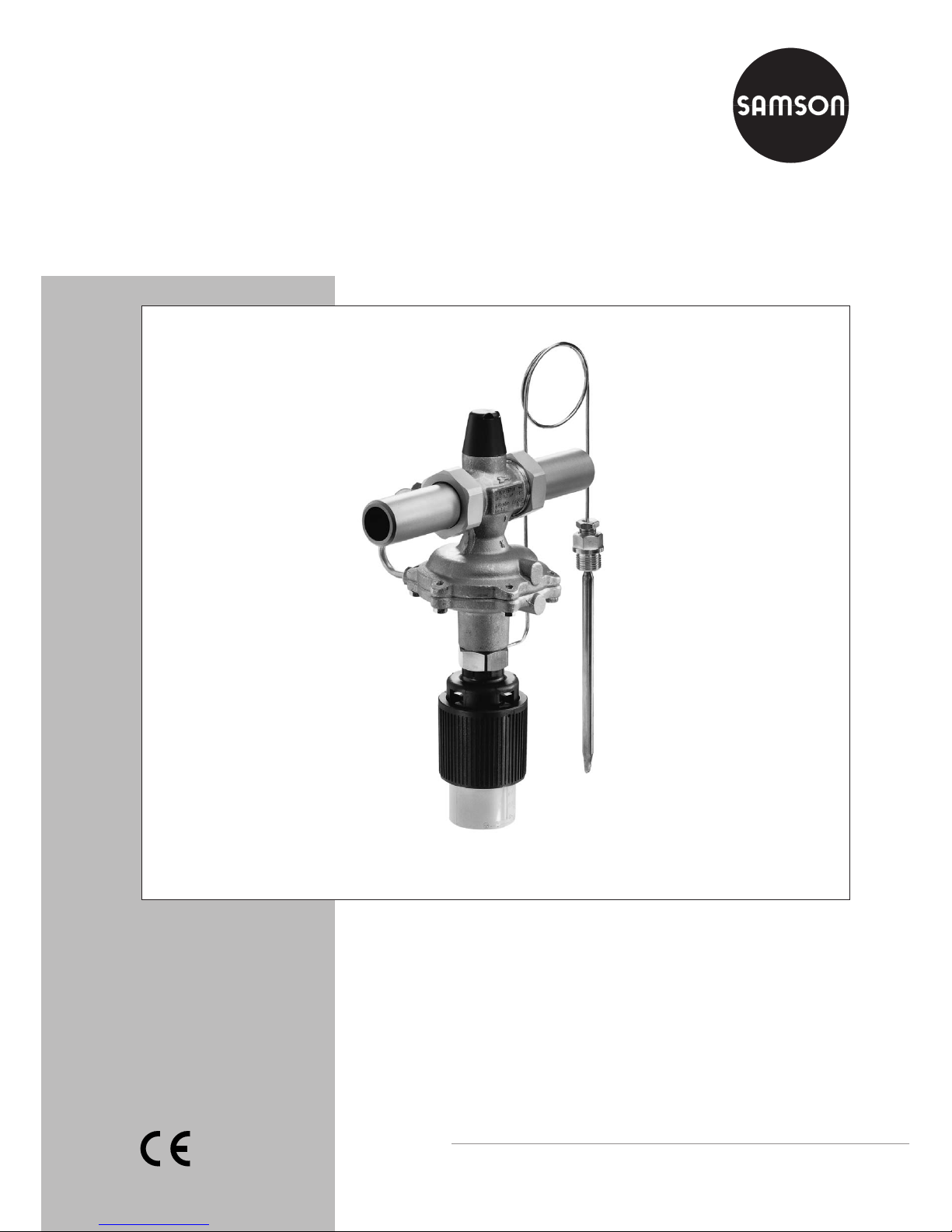
Flow and Temperature Regulator
Type 2469/2430 K
Mounting and
Operating Instructions
EB 3132-2 EN
Edition November 2011
Fig. 1 · Type 2469/2430 K
Page 2

2 EB 3132-2 EN
Contents
Contents Page
1 Design and principle of operation . . . . . . . . . . . . . . . . . . . . . . 4
2 Installation . . . . . . . . . . . . . . . . . . . . . . . . . . . . . . . . . 4
2.1 Mounting position . . . . . . . . . . . . . . . . . . . . . . . . . . . . . . 4
2.1.1 Strainer . . . . . . . . . . . . . . . . . . . . . . . . . . . . . . . . . . . 4
2.1.2 Additional installation instructions . . . . . . . . . . . . . . . . . . . . . . 6
2.2 Installing the temperature sensor . . . . . . . . . . . . . . . . . . . . . . . 6
2.2.1 Capillary tube . . . . . . . . . . . . . . . . . . . . . . . . . . . . . . . . 6
2.3 Mounting the thermostat . . . . . . . . . . . . . . . . . . . . . . . . . . . 6
3 Operation. . . . . . . . . . . . . . . . . . . . . . . . . . . . . . . . . . 7
3.1 Start-up . . . . . . . . . . . . . . . . . . . . . . . . . . . . . . . . . . . 7
3.2 Set point adjustment . . . . . . . . . . . . . . . . . . . . . . . . . . . . . 8
3.2.1 Flow rate . . . . . . . . . . . . . . . . . . . . . . . . . . . . . . . . . . 8
3.2.2 Temperature. . . . . . . . . . . . . . . . . . . . . . . . . . . . . . . . . 8
4 Maintenance – Replacing parts . . . . . . . . . . . . . . . . . . . . . . . 8
4.1 Cleaning or replacing the plug . . . . . . . . . . . . . . . . . . . . . . . . 9
4.2 Replacing the diaphragm . . . . . . . . . . . . . . . . . . . . . . . . . . 9
5 Troubleshooting . . . . . . . . . . . . . . . . . . . . . . . . . . . . . . 10
6 Description of the nameplate . . . . . . . . . . . . . . . . . . . . . . . . 11
7 Customer inquiries . . . . . . . . . . . . . . . . . . . . . . . . . . . . . 12
8 Dimensions in mm and weights . . . . . . . . . . . . . . . . . . . . . . 12
CAUTION!
indicates a hazardous situation which, if not
avoided, may result in injury.
NOTICE
indicates a property damage message.
Note: Supplementary explanations, informa
-
tion and tips
Definitions of the signal words used in these instructions
Page 3

EB 3132-2 EN 3
Safety instructions
General safety instructions
4
The regulator is to be mounted, started up or serviced by fully trained and
qualified personnel only, observing the acceptedindustry codes andpractices.
Make sure employees or third persons are not exposed to any danger.
All safety instructions and warnings in these mounting and operating instruc
tions, particularly those concerning assembly, start-up and maintenance, must
be observed.
4
According to these mounting and operating instructions, trained personnel is
referred to as individuals who are able to judge the work they are assigned to
and recognize possible dangers due to their specialized training, their knowl
edge and experience aswell as their knowledgeof theapplicable standards.
4
The regulator fulfils the requirements of the European Pressure Equipment Di
rective 97/23/EC. Valves with a CE marking have a declaration of conformity
that includes information aboutthe appliedconformity assessment procedure.
The declaration of conformity is available on request.
4
For appropriate operation, make sure that the regulator is only used in areas
where the operating pressure and temperatures do not exceed the operating
values specified in the order that the valve sizing data are based on.
The manufacturer does not assume any responsibility for damage caused by
external forces or any other external influence!
Any hazards that could be caused in the regulator by the process medium, the
operating pressure or by moving parts are tobe preventedby meansof theappropriate measures.
4
Proper shipping and storage are assumed.
Note! Non-electric actuator and valve versions do not have their own potential ig
-
nition source according to the risk assessment stipulated in EN 13463-1:2009,
section 5.2, even in the rare incident of an operating fault. Therefore, such valve
versions do not fall within the scope of Directive 94/9/EC. For connection to the
equipotential bonding system, observe section 6.3 of EN 60079-14:2008
VDE 0165-1.
Page 4

1 Design and principle of oper
-
ation
The regulator consists of the Type 2469 Valve
with restriction (orifice), seat and plug, the
closing actuator with operatingdiaphragm as
well as the thermostat with set point adjuster,
capillary tube and temperature sensor.
The regulator isdesigned to keep theflow rate
and temperature constant at the adjusted set
point. The valve closes when the controlled
variable increases.
Versions for safety equipment are addition
-
ally equipped with a Type 2403 Safety Ther
mostat to function as safety temperature monitors (FR/TR/STM). They can also be
equipped with a Type 2439 K Safety Thermostat to function as safety temperature limiters
(FR/TR/STL). For further details, refer to the
Mounting and Operating Instructions:
EB 2183 EN for Type 2403 and
EB 2185 EN for Type 2439 K.
The medium flows through the valve in the direction indicated by the arrow on the body.
The flow rate is determined by the area re
leased between the adjustable restriction
(1.2) and the valve plug (3).
The high pressure upstream of the restriction
is transmitted through the attached control
line to the high-pressure side of the actuator.
The low pressure created downstream of the
restriction acts on the low-pressure side of the
operating diaphragm (6.1) through a bore in
the plug.
The differential pressure created by the re
striction is converted into a positioning force
at the operatingdiaphragm. This forceis used
to move the valve plug depending on the
force of the positioning spring (5).
The medium temperature creates a pressure
in the temperature sensor, which is transmit
-
ted through the capillary tube (24) to the op
erating bellows (23) where is it converted into
a positioning force. This force moves the cou
pling rod (8) and thus the valve plug (3) de
pending on the force of the spring (21)
pretensioned by the set point adjuster (22).
The largest signal isused toactuate thevalve.
2 Installation
Choose a place of installation where the per
missible ambient temperature of 80 °C is not
exceeded.
NOTICE
Protect the regulator against frost when it is
used to control freezing process media.
2.1 Mounting position
Install the regulator in a horizontal pipeline
with the actuator and thermostat vertically
suspended (pointing down). Regulators in
DN 15 to 25 can also be installed in vertical
pipelines.
Use the includedconnection nuts with welding
ends to connect the regulator. Make sure the
direction of flow matches the arrow on the
valve body.
2.1.1 Strainer
Install a strainer (SAMSON Type 1NI) up
stream of the regulator to prevent that any
sealing parts, weld spatter and other impuri
ties carried along by the process medium im
pair the proper functioning of the valve,
above all the tight shut-off.
4 EB 3132-2 EN
Design and principle of operation
Page 5
EB 3132-2 EN 5
Installation
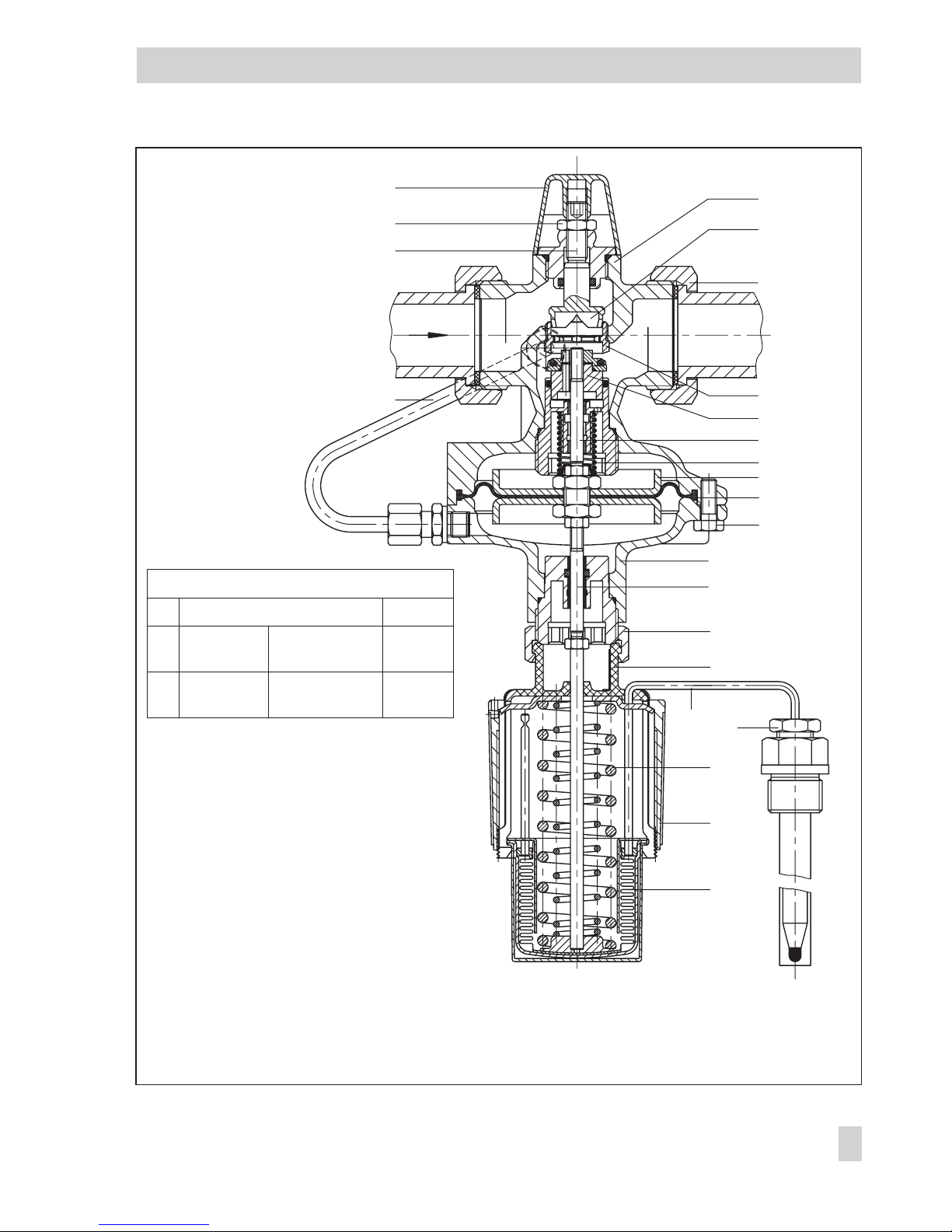
Tightening torques
Nm
10 Coupling nut
20
3 Plug section
DN 15 to 25
DN 32 to 50
70
110
7 Screws
DN 15 to 25
DN 32 to 50
8
18
14
13
12
11
1
1.2
1.1
2
3
4
5
6.2
6.1
7
6
8
10 (20Nm)
20
24
25
21
22
23
Fig. 2 · Sectional drawing
1 Valve body
1.1 Connection nut with
gasket and welding
end
1.2 Restriction (orifice
plate)
2 Seat
3 Plug section with
guide nipple
4 Plug stem
5 Positioning spring
6 Actuator
6.1 Operating diaphragm
6.2 Diaphragm plate
7 Body screws
8 Coupling rod
10 Coupling nut
11 Control line
12 Set point screw
13 Lock nut
14 Cap
20 Control thermostat
21 Spring
22 Set point adjuster
23 Bellows with actuator
stem
24 Capillary tube
25 Temperature sensor
Page 6

Install the strainer with the direction of flow
matching the arrow on the body. Make sure
the filter element is vertically suspended. Re
-
member to leave enough space to remove it.
2.1.2 Additional installation in
-
structions
We recommend to install a hand-operated
shut-off valve both upstream of the strainer
and downstream of theregulator to beable to
shut down the plant for cleaning and mainte
nance.
To monitor the pressures in the plant, install a
pressure gauge both upstream and down
stream of the regulator.
To check the adjusted set point, we recommend to install a thermometer near the sensor
that extends into the process medium.
2.2 Installing the temperature
sensor
Refer to Mounting and Operating Instructions
EB 2430 EN for details on the Type 2430 K
Thermostat and to EB 2430-3 EN for details
on the Type 2430 K Thermostat (vapor pres
sure).
The temperature sensor may be installed in
any desired position. Make sure its entire
length is immersed in the process medium.
Choose a place of installation where neither
overheating nor considerable idle times oc
cur.
Weld in a sleeve with G ½ or G ¾ female
thread at the place of installation.
Seal the screw gland or thermowell into the
welded-in sleeve. Insert the sensor and fasten
it with the clamping screw.
NOTICE
To prevent damage caused by corrosion,
make sure to use the same kinds of materials
when installing a sensor or thermowell. For
example, avoid using a thermowell or tem
perature sensor made of non-ferrous metal in
a stainless steel heat exchanger. In this case,
the sensor is to be used together with a stain
less steel thermowell.
2.2.1 Capillary tube
Install the capillary tube such that no mechan
ical damage can occur. The smallestpermissi
ble bending radius is 50 mm.
Roll up the excess tube to form a ring; never
bend or shorten it.
Make sure the capillary tube is not exposed to
excessive temperature fluctuations.
2.3 Mounting the thermostat
Place the thermostat on the connection of the
actuator and tighten it using the coupling
nut (10) and a tightening torque of 20 Nm.
6 EB 3132-2 EN
Installation
Page 7

3 Operation
3.1 Start-up
NOTICE
Open the restriction (1.2) used to adjust the
flow rate before starting up the regulator.
Fill the plant slowly.
CAUTION!
When pressure-testing the pipelines with the
regulator installed, the test pressure must not
exceed 1.5 times the nominal pressure.
EB 3132-2 EN 7
Operation
1
2
3
4
5
6
7
8
9
10
11
0.01 0.02 0.03 0.05 0.1 0.2 0.3 0.5 1 2 3 4 5 6 78 910 15
0.4K
VS
1 2.5
V
m
3
/h
DN 15
DN20,
K
VS
6.3
DN25,
KVS8
DN32,
KVS12.5
DN40,
KVS16/20
3)
DN50,
K
VS
20/25
3)
4
Nominal size
DN 15 20 25 32 40
2)
50
2)
KVScoefficient
0.4
1)
1
1)
2.5 4
1)
6.3 8 12.5 16/203)20/25
3)
Flow rate set
point range
m³/h
0.01
to 0.2
0.02
to 0.64
0.02
to 1.2
0.1
to 2.5
0.1
to 3.6
0.1 to 5
0.3
to 10
0.4
to 12.5
0.4
to 15
1)
Special versions
2)
Also as version with flanged body
3)
KVSwith flanged body
Fig. 3 · Flow rate diagram
Turns of the
set point screw
Page 8

3.2 Set point adjustment
3.2.1 Flow rate
Proceed as follows to set or change the flow
rate set point:
Unscrew the cap (14).
Loosen the lock nut (13) and turn the set point
screw:
4
Turn the screw clockwise (P)toreduce
the flow rate.
4
Turn the screw counterclockwise (Q)to
increase the flow rate.
The diagram serves as a guide for flow rate
adjustment. The required number of turns of
the set point screw is based on a closed restriction (1.2).
Refer to the regulator's nameplate for the adjustable set point range. In DN 15, several
ranges are possible due to the different flow
coefficients (see table).
When the desired flow rate value has been
reached, tighten the lock nut and screw the
cap back on.
In the special version with scaled cap, the set
point can be adjusted directly (one scale
marking equals one turn of the set point
screw).
3.2.2 Temperature
Adjust the set point on the black plastic ring
(set point adjuster 22; continuously adjust
-
able) observing the reference thermometer.
4
Turn the adjuster clockwise to reduce (P)
the temperature.
4
Turn the adjuster counterclockwise (Q)to
increase the temperature.
The adjusted temperature set point can be
lead-sealed through the bore in the set point
adjuster.
4 Maintenance – Replacing
parts
The regulator is maintenance free. Neverthe
less, it is subject to natural wear, particularly
at the seat, plug and operating diaphragm.
Depending on the operating conditions, the
regulator needs to be checked at regular in
tervals to detect and remove possible mal
functions.
If the regulator's tight shut-off is impaired,
there may be either dirt or natural wear on
the seat and plug.
If the flow rate deviates considerably from the
adjusted set point, leak-test the operating diaphragm and replace it, if necessary.
CAUTION!
For installation and maintenance
work on theregulator, makesure the
relevant plant section has been
depressurized and, depending on
the process medium, drained as
well.
For high medium temperatures, al
-
low the plant section to cool down to
ambient temperature before starting
any work.
We recommend to remove the regu
-
lator from the pipeline.
8 EB 3132-2 EN
Maintenance – Replacing parts
Page 9

4.1 Cleaning or replacing the
plug
1. Remove the regulator from the pipeline.
2. Unscrew the control line (11).
3. Unscrew the body screws (7) and remove
the lower diaphragm case including the
diaphragm (6.1) and diaphragm plate.
4. For sizes DN 15 to 25, unscrew the guide
nipple of the plug section (3) using a
socket wrench (order no. 1280-3001)
and pull it out.
This wrench can also be made, for exam
ple from a GEDORE screwdriver bit
(IN 19-19) by boring a 17-mm-deep hole
(Ø 17) into the 19 mm hexagon bit (see
Fig. 4)
For sizes DN 32 to 50, unscrew the stopper and pull out the plug section.
5. Thoroughly clean the seat and plug section.
Check that the control line is not clogged.
If the plug is damaged, replace the entire
plug section.
4
Reassemble the regulator in reverse or
der, observing the tightening torques
given in the table in Fig. 2.
4.2 Replacing the diaphragm
1. Unscrew the control line (11).
2. Unscrew the body screws (7) and remove
the lower diaphragm case including the
diaphragm (6.1) and diaphragm plate.
3. Replace the diaphragm complete with the
diaphragm plate.
4
Reassemble the regulatorin reverse order,
observing the tightening torques given in
the table in Fig. 2.
EB 3132-2 EN 9
Maintenance – Replacing parts
17
Ø 17
SW 19
Fig. 4 · Socket wrench
Page 10

5 Troubleshooting
10 EB 3132-2 EN
Troubleshooting
Fault Possible cause Solution
Flow rate Leakage between seat and plug Remove the regulator from the pipeline. Clean
the seat and plug. If necessary, replace the plug
(section 4.1). Otherwise, return the regulator to
SAMSON for repair.
Flow rate set point
exceeded
Operating diaphragm defective Replace the diaphragm (section 4.2) or return
the regulator to SAMSON for repair.
Control line clogged Remove the control line and clean it.
Valve too large for control task Recalculate the K
VS
coefficient and contact
SAMSON.
Flow rate set point
not reached
Set point range incorrectly
selected
Check the set point range and contact
SAMSON.
Safety device (e.g. pressure
limiter) triggered
Check the plant. Unlock the safety device.
Insufficient differential pressure
across the plant
Compare the existing differential pressure across
the plant with the plant drag.
Min. differential pressure = differential pressure
at restriction + (
V
•
/KVS)²
Strainer clogged Drain the strainer's filter and clean it.
Valve incorrectly installed Install the regulator with the direction of flow
matching the arrow on the valve body.
Temperature Leakage between seat and plug Remove the regulator from the pipeline. Clean
the seat and plug. If necessary, replace the plug
(section 4.1). Otherwise, return the regulator to
SAMSON for repair.
Temperature set
point at the sensor
exceeded or not
reached
Sensor installed in the wrong
location
Check that the sensor is fully immersed in the
process medium. Check that it is not installed in
a place where idle times or heat accumulation
occur.
Safety device (e.g. safety tem
perature limiter or monitor)
triggered
Check the plant. Unlock the safety device.
Temperature set
point at the sensor
exceeded
Insufficient energy available for
heating or cooling
Draw up an energy balance.
Thermostat defective Return the thermostat to SAMSON for repair.
Page 11

6 Description of the nameplate
EB 3132-2 EN 11
Description of the nameplate
Control loop
oscillates
Valve too large for control task Recalculate the K
VS
coefficient and contact
SAMSON.
Time constant too large for con
-
trol loop
Fill the thermowell with conductive paste, remove
the thermowell and use a sensor with a smaller
time constant.
Fig. 5 · Nameplate
1 Model number
2 Modification index
3 Date of manufacture
4 Type designation
Entries in the other spaces:
K
VS
or CVcoefficient
Upper differential pressure in bar or psi
Flow rate set point in m³/h
Max. permissible temperature in °C or °F
Max. permissible differential pressureDp
Nominal pressure as PN or ANSI Class
1 2
4
3
Page 12

7 Customer inquiries
If malfunctions or defects occur, contact the SAMSON After-sales Service for support.
The addresses of SAMSON AG, its subsidiaries, representatives and service facilities world
wide can be found on the Internet at www.samson.de, in a SAMSON product catalog or on the
back of these mounting and operating instructions.
Include the following details when making inquiries:
4
Regulator type and nominal size
4
Model number
4
Threaded or flange connection
4
Upstream and downstream pressures
4
Flow rate in m³/h
4
Has a strainer been installed?
4
Installation drawing
8 Dimensions in mm and weights
Nominal size
DN 15 DN 20 DN 25 DN 32 DN 40 DN 50
Pipe Ø d
21.3 26.8 32.7 42 48 60
Connection R
G ¾ G 1 G 1¼ G 1¾ G 2 G 2½
Width across flats SW
30 36 46 59 65 82
Length L
65 70 75 100 110 130
Height H
32 45
Height H1
245 265 295
Standard version
Welding ends L1
210 234 244 268 294 330
Approx. weight in kg
2.4 2.5 2.7 4.0 6.2 7.0
Special version with threaded ends (male thread)
Length L2
129 144 159 180 196 228
Male thread A
G ½ G ¾ G 1 G 1¼ G 1½ G 2
Approx. weight in kg
2.2 2.3 2.4 5.9 6.4 6.9
Special version with flanges PN 16 or PN 25, or version with flanged body (DN 32, DN 40 and DN 50)
Length L3
130 150 160 180 200 230
Approx. weight in kg
3.6 4.3 4.9 9.1 10.4 11.9
12 EB 3132-2 EN
Customer inquiries
Page 13

EB 3132-2 EN 13
Dimensions in mm and weights
L3
L3
L
L2
L
A
SW
SW
SW
L1
L
59
(85)
245 (295)
dR
G½
(G¾)
G½
(G¾)
185 (220)
185 (220)
Ø12 (Ø19)
Ø9.5 (Ø16)
Fig. 6 · Dimensional drawings
Connection nuts
with threaded ends
Connection nuts
with flanges
Flanged body
DN 32, 40 and 50
Connection nuts
with welding ends
Values in parentheses
for DN 32 to 50
Version with
thermowell
Bulb sensor with
screw gland
Page 14

14 EB 3132-2 EN
Page 15

EB 3132-2 EN 15
Page 16

SAMSON AG · MESS- UND REGELTECHNIK
Weismüllerstraße 3 · 60314 Frankfurt am Main · Germany
Phone: +49 69 4009-0 · Fax: +49 69 4009-1507
Internet: http://www.samson.de
EB 3132-2 EN
S/Z 2011-12
 Loading...