

Page 1
Mounting and
Operating Instructions
EB 2183 EN
Translation of original instructions
Edition June 2018
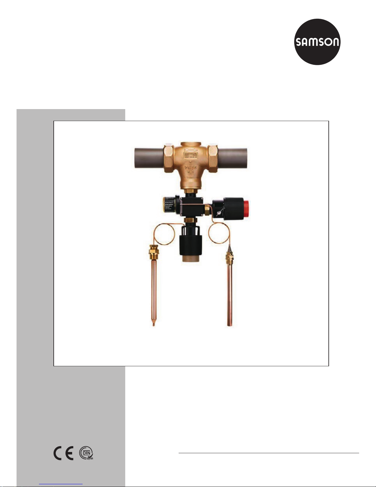
Type2432/2430/2403 TR/STM
Self-operated Temperature Regulators
Type 2403 Safety Temperature Monitor
(STM)
Page 2
2 EB 2183 EN
Note on these mounting and operating instructions
These mounting and operating instructions assist you in mounting and operating the device
safely. The instructions are binding for handling SAMSON devices.
Î For the safe and proper use of these instructions, read them carefully and keep them for
later reference.
Î If you have any questions about these instructions, contact SAMSON‘s After-sales Service
Department (aftersalesservice@samson.de).
The mounting and operating instructions for the devices are included in
the scope of delivery. The latest documentation is available on our website
(www.samson.de) > Product documentation. You can enter the document
number or type number in the [Find:] eld to look for a document.
Denition of signal words
Hazardous situations which, if not avoided,
will result in death or serious injury
Hazardous situations which, if not avoided,
could result in death or serious injury
Property damage message or malfunction
Additional information
Recommended action
DANGER
!
WARNING
!
NOTICE
!
Note
Tip
Page 3

Contents
EB 2183 EN 3
1 Safety instructions and measures ...................................................................4
1.1 Notes on possible severe personal injury .........................................................6
1.2 Notes on possible personal injury ...................................................................7
1.3 Notes on possible property damage ................................................................8
2 Markings on the device .................................................................................9
2.1 Material number ............................................................................................9
3 Design and principle of operation ................................................................10
3.1 Technical data .............................................................................................12
3.2 Process medium and scope of application ......................................................12
4 Measures for preparation ............................................................................18
4.1 Unpacking ..................................................................................................18
4.2 Transporting and lifting ................................................................................18
4.3 Storage .......................................................................................................18
4.4 Preparation for installation ............................................................................19
5 Mounting and start-up ................................................................................. 19
5.1 Mounting the safety temperature monitor onto the valve ..................................19
5.2 Additional ttings .........................................................................................20
5.3 Combination with control thermostat ..............................................................20
5.4 Installing the valve into the pipeline ...............................................................21
5.4.1 Installation conditions ...................................................................................21
5.4.2 Installing the temperature sensor ...................................................................21
5.5 Start-up ....................................................................................................... 23
5.5.1 Gases and liquids ........................................................................................23
5.5.2 Steam .........................................................................................................23
6 Operation ...................................................................................................24
6.1 Adjusting the limit temperature ......................................................................24
6.2 Fine adjustment of the limit temperature .........................................................25
7 Servicing.....................................................................................................26
7.1 Preparation for return shipment ..................................................................... 26
8 Malfunctions ...............................................................................................27
9 Decommissioning and disassembly ..............................................................28
9.1 Decommissioning .........................................................................................28
9.2 Disposal ......................................................................................................28
10 Appendix ....................................................................................................29
10.1 After-sales service and spare parts ................................................................29
10.2 Certicates ..................................................................................................29
Page 4

4 EB 2183 EN
Contents
1 Safety instructions and measures
Intended use
The Type2403 Safety Temperature Monitor (STM) with valve is designed for temperature
monitoring and control of the energy supply to heat generators (e.g. heat exchangers) by
closing the valve. The connection of an additional Type2430 Control Thermostat converts the
safety temperature monitor (STM) into a temperature regulator with safety temperature
monitor (TR/STM).
The devices are designed to operate under exactly dened conditions (e.g. operating
pressure, process medium, temperature). Therefore, operators must ensure that the devices
are only used in operating conditions that meet the specications used for sizing the devices
at the ordering stage. In case operators intend to use the devices in other applications or
conditions than specied, contact SAMSON.
SAMSON does not assume any liability for damage resulting from the failure to use the
device for its intended purpose or for damage caused by external forces or any other
external factors.
Î Refer to the technical data and nameplate for limits and elds of application as well as
possible uses.
Reasonably foreseeable misuse
The devices are not suitable for use outside the limits dened during sizing and by the techni-
cal data. Furthermore, the following activities do not comply with the intended use:
− Use of non-original spare parts
− Performing service and repair work not described in these instructions
Qualications of operating personnel
The devices must be mounted, started up, serviced and repaired by fully trained and
qualied personnel only; the accepted industry codes and practices are to be observed.
According to these mounting and operating instructions, trained personnel refers to
individuals who are able to judge the work they are assigned to and recognize possible
hazards due to their specialized training, their knowledge and experience as well as their
knowledge of the applicable standards.
Personal protective equipment
We recommend checking the hazards posed by the process medium being used (e.g.
uGESTIS (CLP) hazardous substance database).
Page 5

EB 2183 EN 5
Safety instructions and measures
Î Provide protective equipment (e.g. safety gloves, eye protection) appropriate for the pro-
cess medium used.
Î Wear hearing protection when working near the valve.
Î Check with the plant operator for details on further protective equipment.
Revisions and other modications
Revisions, conversions or other modications of the product are not authorized by SAMSON.
They are performed at the user's own risk and may lead to safety hazards, for example. Fur-
thermore, the product may no longer meet the requirements for its intended use.
Warning against residual hazards
To avoid personal injury or property damage, plant operators and operating personnel must
prevent hazards that could be caused in the device by the process medium, the operating
pressure or by moving parts by taking appropriate precautions. They must observe all hazard statements, warning and caution notes in these mounting and operating instructions, especially for installation, start-up and service work.
We also recommend checking the hazards posed by the process medium being used (e.g.
uGESTIS (CLP) hazardous substance database).
Î Observe safety measures for handling the device as well as re prevention and explosion
protection measures.
Responsibilities of the operator
The operator is responsible for proper operation and compliance with the safety regulations.
Operators are obliged to provide these mounting and operating instructions as well as the
referenced documents to the operating personnel and to instruct them in proper operation.
Furthermore, the operator must ensure that operating personnel or third persons are not exposed to any danger.
Responsibilities of operating personnel
Operating personnel must read and understand these mounting and operating instructions as
well as the referenced documents and observe the specied hazard statements, warnings
and caution notes. Furthermore, the operating personnel must be familiar with the applicable
health, safety and accident prevention regulations and comply with them.
Page 6

6 EB 2183 EN
Safety instructions and measures
Referenced standards and regulations
The devices comply with the requirements of the European Pressure Equipment Directive
2014/68/EU. Devices with a CE marking have an EU declaration of conformity, which includes information about the applied conformity assessment procedure. This EU declaration
of conformity is included in the Appendix of these instructions (see section10.2).
Non-electric valve versions whose bodies are not lined with an insulating material coating do
not have their own potential ignition source according to the risk assessment stipulated in
EN13463-1:2009, section5.2, even in the rare incident of an operating fault. Therefore,
such valve versions do not fall within the scope of Directive 2014/34/EU.
Î For connection to the equipotential bonding system, observe the requirements specied in
section 6.4 of EN60079-14 (VDE0165 Part 1).
Referenced documentation
The following documents apply in addition to these mounting and operating instructions:
− Mounting and operating instructions for valves, e.g. uEB2171, uEB2172 and
uEB2173
− Mounting and operating instructions for the control thermostats, e.g. uEB2430 and
uEB2430-3
− Mounting and operating instructions for the safety temperature limiter, e.g. uEB2185
1.1 Notes on possible severe personal injury
DANGER
!
Risk of bursting in pressure equipment.
Valves and pipelines are pressure equipment. Improper opening can lead to valve
components bursting.
Î Before starting any work on the valve, depressurize all plant sections concerned as
well as the valve.
Î Drain the process medium from all the plant sections concerned as well as the
valve.
Î Wear personal protective equipment.
Page 7

EB 2183 EN 7
Safety instructions and measures
1.2 Notes on possible personal injury
WARNING
!
Risk of personal injury due to residual process medium in the valve.
While working on the valve, residual process medium can escape and, depending on
its properties, may lead to personal injury, e.g. (chemical) burns.
Î If possible, drain the process medium from all the plant sections concerned and the
valve.
Î Wear protective clothing, safety gloves and eyewear.
Risk of burn injuries due to hot or cold components and pipelines.
Depending on the process medium, valve components and pipelines may get very hot
or cold and cause burn injuries.
Î Allow components and pipelines to cool down or heat up.
Î Wear protective clothing and safety gloves.
Damage to health relating to the REACH regulation.
If a SAMSON device contains a substance which is listed as being a substance of very
high concern on the candidate list of the REACH regulation, this circumstance is indicated on the SAMSON delivery note.
Î Information on safe use of the part affected,
see uhttp://www.samson.de/reach-en.html.
Page 8

8 EB 2183 EN
Safety instructions and measures
1.3 Notes on possible property damage
NOTICE
!
Risk of irreparable regulator damage caused by the regulator components being
taken apart.
The thermostat, set point adjuster and capillary tube form an inseparable hydraulic
unit. If these components are dismantled (e.g. removal of the capillary tube), the regulator will be irreparably damaged and will no longer be able to fulll its monitoring
and control task.
Î Do not dismantle the regulator.
Î Only perform allowed activities on the regulator.
Î Contact SAMSON's After-sales Service department before replacing spare parts.
Risk of valve damage due to contamination (e.g. solid particles) in the pipeline.
The plant operator is responsible for cleaning the pipelines in the plant.
Î Flush the pipelines before start-up.
Î Observe the maximum permissible pressure for valve and plant.
Risk of valve damage due to unsuitable medium properties.
The valve is designed for a process medium with dened properties.
Î Only use the process medium specied during sizing.
Risk of leakage and valve damage due to excessively high or low tightening
torques.
Observe the specied torques on tightening valve components.
Excessively tightened torques lead to parts wearing out quicker. Parts that are too loose
may cause leakage.
Î Observe the specied tightening torques.
Page 9

EB 2183 EN 9
Markings on the device
2 Markings on the device
SAMSON
2750-5
2403
... °C
...°F
STM 60104
1
2
3
Specications on the scaled cap on the adjustment knob to adjust the limit
1 Model number
2 Limit value range in °C and °F
3
Register number (type test
according to DINEN14597)
Specications on the valve
1 Type designation (valve)
2 Conguration ID
3 Date of manufacture
4 K
VS/CV
5 Max. permissible temperature
6 Nominal pressure (valve)
7 Max. permissible differential
pressure ∆p
SAMSON 1
2710 - 2 3
4 5
6 7
Fig.1: Nameplate
2.1 Material number
Specifying the conguration ID, you can contact us to nd out which material is used. The
conguration ID is specied on the nameplate (2, conguration ID). For more details on the
nameplate, see Fig.1.
Page 10

10 EB 2183 EN
Design and principle of operation
3 Design and principle of oper-
ation
The Type2403 Safety Temperature Monitor
(STM) with a valve operates without auxiliary energy and is designed for extended safety according to DINEN14597. The safety
temperature monitor is used to limit the temperature by closing a SAMSON Series43
Valve connected to the safety thermostat.
The safety temperature monitor mainly
consists of a valve and safety thermostat with
capillary tube (8) and bulb sensor (9).
The connection of an additional Type2430
Control Thermostat (20) converts the safety
temperature monitor (7) into a temperature
regulator with safety temperature monitor
(TR/STM). See Fig.2.
The valve is closed by a spring mechanism
when the temperature reaches the adjusted
limit, when the capillary tube breaks or
when leakage occurs in the sensor system.
The safety temperature monitor works according to the vapor pressure principle. The
temperature of the medium creates a pressure in the temperature sensor (9) which is
proportional to the measured temperature.
This pressure is transferred through the capillary tube (8) to the bellows of the operating
element (10) and converted into a position-
ing force. The force is transferred over the
pin (11) of the operating element to the plug
stem (4) of the valve and the plug (3). The
position of the plug determines the ow rate
of the heat transfer medium across the area
released between the seat (2) and plug.
The safety temperature monitor closes the
valve when the temperature reaches the ad-
justed limit temperature. The safety tempera-
ture monitor resets itself automatically when
the temperature has fallen to a value of ap-
prox. 5K below the adjusted limit tempera-
ture.
Fail-safe position
When the capillary tube ruptures or there is
a leak in the sensor, the spring mechanism
reacts to the reduced system pressure and
the pin of the operating element (11) closes
the valve. The valve cannot be reset. In this
case, the Type2403 Safety Temperature
Monitor must be replaced.
The adjusted limit temperature must have a
minimum temperature difference of 15K to
the set point of the temperature regulator.
Note
Page 11
EB 2183 EN 11
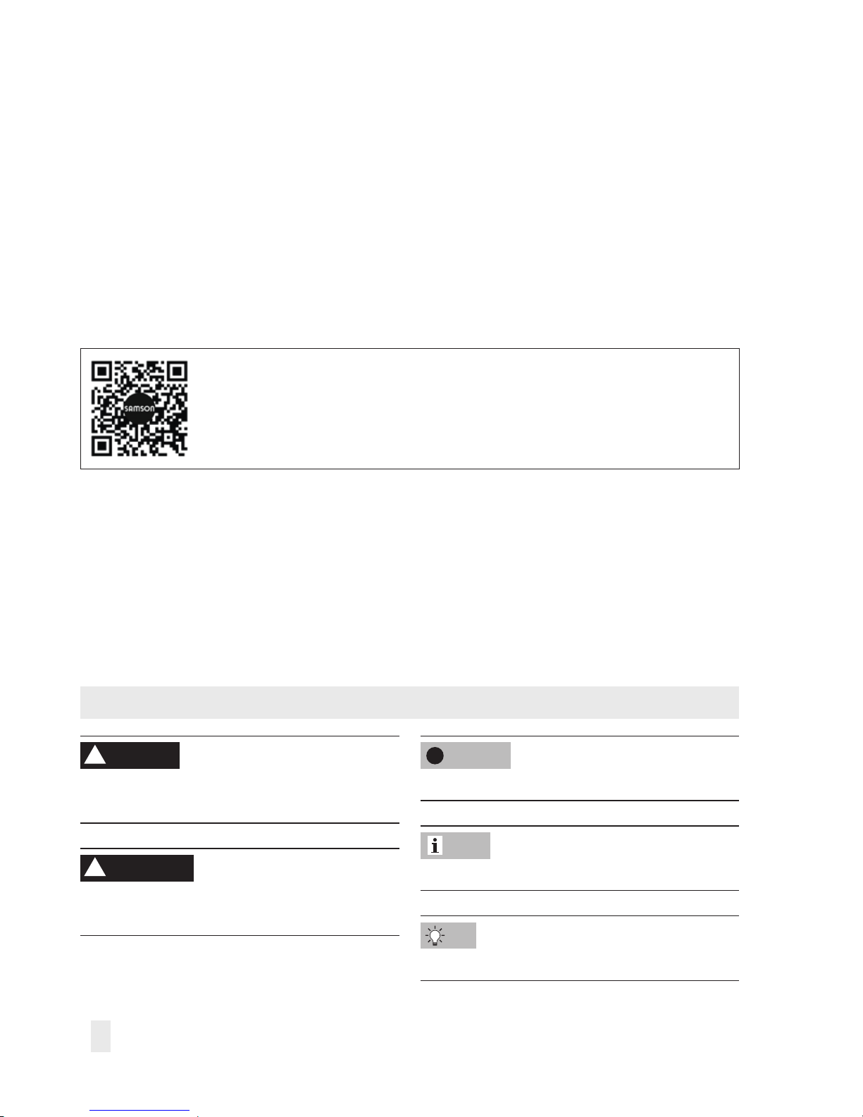
Design and principle of operation
1 Valve body
2 Seat
3 Plug
4 Plug stem
5 Valve spring
6 Coupling nut
7 Type 2403 Safety Temperature Monitor (STM)
8 Capillary tube
9 Temperature sensor
10 Operating element
11 Pin of operating element
12 Limit adjustment knob
13 Lead-seal hole
14 Mounting location for Type2430 Thermostat
20 Type 2430 Thermostat (optional)
1
2
3
4
5
6
11
10
12
8
9
13
7
6
14
20
Tightening torque for coupling
nut (6): 20Nm
Note
Fig.2: Design and principle of operation (TR/STM)
Page 12

12 EB 2183 EN
Design and principle of operation
3.1 Technical data
3.2 Process medium and scope
of application
Safety temperature monitoring of the energy
supply for heat generators or heat exchangers by closing the valve.
For limit signals from 60 to 120°C·Valves
G½ to G1·DN15 to 50·Nominal pres-
sure PN16 or 25·Max. 200°C
The Type2403 Safety Temperature Monitor
(STM) with a valve operates without auxiliary
energy and is designed for extended safety
according to DINEN14597. The valve is
closed by a spring mechanism when the
temperature reaches the adjusted limit, when
the capillary tube breaks or when leakage
occurs in the sensor system. The devices are
automatically reset and put back into
operation after the temperature has fallen
below the limit and the fault has been
remedied.
Further details and technical data of the
valves and control thermostats are listed in
the following mounting and operating instructions:
− Mounting and operating instructions for
valves, e.g. uEB2171, uEB2172 und
and uEB2173
− Mounting and operating instructions for
the control thermostats, e.g. uEB2430
and uEB2430-3
− Mounting and operating instructions for
the safety temperature limiter, e.g.
uEB2185
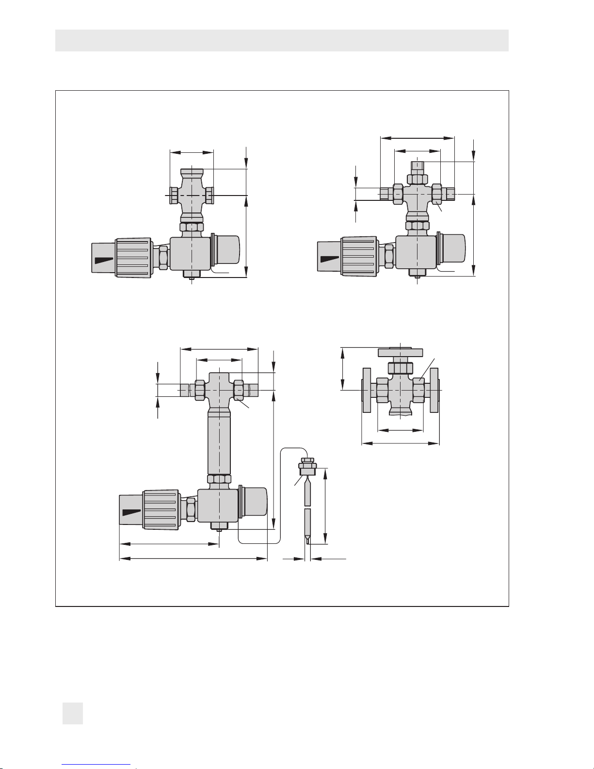
Dimensions and weights
Table2 and Table3 provide a summary of
the dimensions and weights. The lengths and
heights are shown in the dimensional draw-
ings (Fig.3 to Fig.5).
Typetesting
The safety temperature monitor is tested by
the German Technical Inspectorate (TÜV) according to DINEN14597 under the type
designation 2750-5. The registration number
is available on request.
Note
Page 13

EB 2183 EN 13
Design and principle of operation
Table1: Technical data · All pressures (gauge)
Type 2403 Safety Temperature Monitor
Connection M32x1.5
Adjustment range of limit value 60 to 75°C·75 to 100°C·100 to 120°C
Permissible ambient temperature Max. 50°C
Perm. temperature at the sensor 25K above the adjusted limit
Perm. pressure at sensor 25bar
Capillary tube length 5m
Compliance
·
Table2: Dimensions in mm
Table 2.1: Type2432/2403·Type2433/2403·Type2436/2403·Type2437/2403
Valve size DN 15 20 25 32 40 50
Pipe Ød d 21.3 26.8 32.7 42 48 60
AF 30 36 46 59 65 82
Length L 65 70 75 100 110 130
With welding ends L1 210 234 244 268 294 330
With threaded ends L2 129 144 159 180 196 228
With anges L3 130 150 160 180 200 230
Male thread A G½ G¾ G1 G1¼ G1½ G2
Type2432/2403
H 140 190
H1 30 55
Type2433/2403
H 135 145
H2 112 122 124 144 157 165
H3 72 77 82 100 108 114
H4 72 80 82 105 110 115
Type2436/2403
H – 160
H1 – 95
Type2437/2403
H 220 270
H1 30 55
Page 14

14 EB 2183 EN
Design and principle of operation
Table 2.2: Type2431/2403·Type2433/2403·Type2435/2403·Type2436/2403
Connection size G½ G¾ G1
Face-to-face dimensions L 65 75 90
Type2431/2403 H 140
Type2433/2403
H 140
H1 40
Type2435/2403 H 220
Type2436/2403
H 145
H1 46
Table3: Weights in kg
Table 3.1: Type2432/2403·Type2433/2403·Type2436/2403·Type2437/2403
Valve size DN 15 20 25 32 40 50
Type2432/2403 kg (approx.)
With welding ends 2.5 2.8 3.1 5.1 5.8 7.6
With threaded ends 2.4 2.7 3.0 5.0 5.7 7.5
With anges 3.9 4.8 5.6 8.3 9.8 11.6
Type2433/2403 kg (approx.)
With welding ends 2.9 3.2 3.4 4.8 5.1 6.4
With threaded ends 2.9 3.2 3.4 4.8 5.1 6.4
With anges 5.0 6.2 7.1 9.6 11 14
Type2436/2403 kg (approx.)
With welding ends
–
3.8 4.2 4.6
With threaded ends 3.8 4.2 4.6
With anges 7.0 8.2 9.6
Type2437/2403 kg (approx.)
With welding ends 2.7 3.0 3.3 5.5 6.2 8.1
With threaded ends 2.6 2.9 3.2 5.5 6.2 8.1
With anges 4.1 5.0 5.8 8.5 10 12
Table 3.2: Type2431/2403·Type2433/2403·Type2435/2403·Type2436/2403
Connection size G½ G¾ G1
Type2431/2403 kg (approx.) 2.0 2.1 2.2
Type2433/2403 kg (approx.) 2.2 2.3 2.4
Type2435/2403 kg (approx.) 2.5 2.6 2.7
Type2436/2403 kg (approx.) 2.4 2.5 2.6
Page 15
EB 2183 EN 15
Design and principle of operation
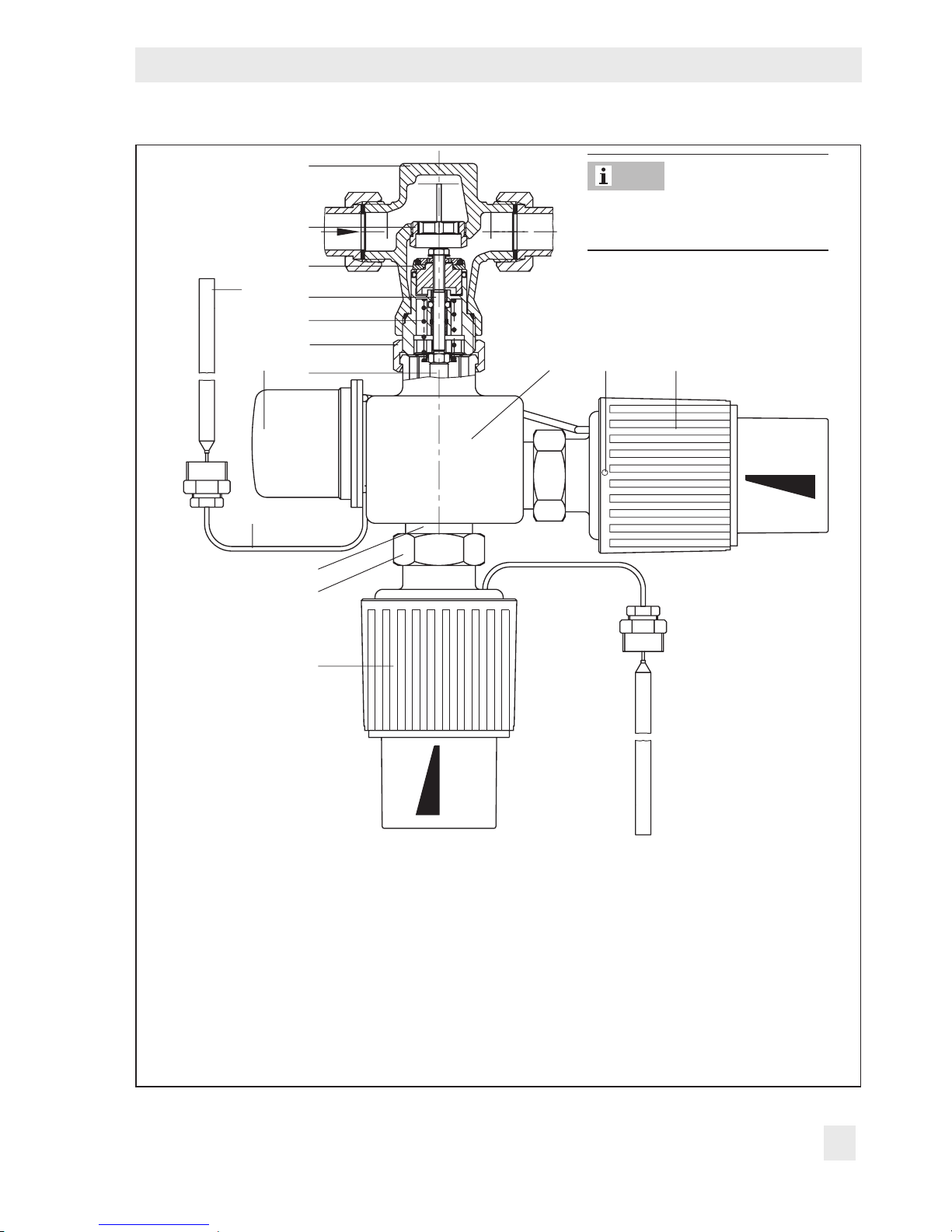
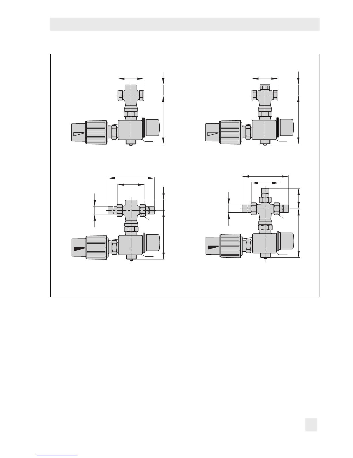
Dimensional drawings of safety temperature monitors (STM)
L
H30
L
HH
1
Type2431/2403·Type2435/2403 Type2433/2403·Version with female thread
L
d
L1
H
SW
H1
L
d
L1
H
SW
H2
Type2432/2403·Type2436/2403 Type2433/2403 · Version with welding ends
Fig.3: Dimensional drawings
Page 16
16 EB 2183 EN
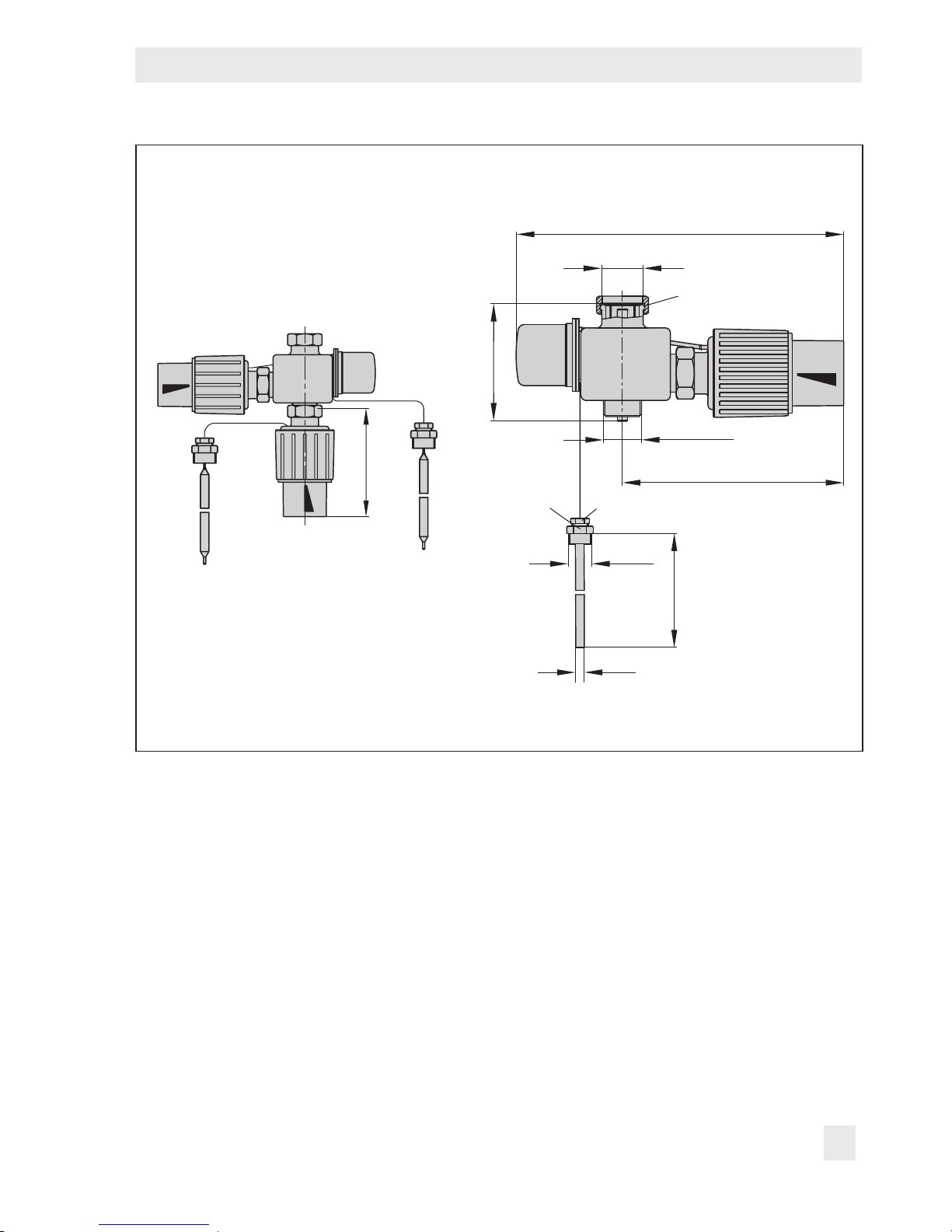
Design and principle of operation
Dimensional drawings of safety temperature monitors (STM)
L
H50
L
A
L2
HH3
SW
Type2436/2403·G½ to G1 Type2433/2403
Version with threaded ends
H4
S
W
L
d
L1
H
170
255
SW
H1
L
L3
Ø12
G½
225
Type2433/2403 · Version with anges
Fig.4: Dimensional drawings
Page 17
EB 2183 EN 17
Design and principle of operation
Dimensional drawings of temperature regulator with safety temperature monitor (TR/
STM)
125
M32 x 1.5
255
SW 36
90
M32 x 1.5
170
SW 17
SW 22
Ø12
250
G ½
Type243 …/2430/2403
Fig.5: Dimensional drawings
Page 18
18 EB 2183 EN
Measures for preparation
4 Measures for preparation
After receiving the shipment, proceed as fol-
lows:
1. Check the scope of delivery. Compare
the shipment received with the delivery
note.
2. Check the shipment for transportation
damage. Report any damage to
SAMSON and the forwarding agent
(refer to delivery note).
4.1 Unpacking
Do not remove the packaging until immediately before mounting it onto the valve.
Proceed as follows to lift and install the device:
1. Remove the packaging from the device.
2. Dispose of the packaging in accordance
with the valid regulations.
Note
4.2 Transporting and lifting
Due to the low service weight, lifting equipment is not required to lift and transport the
safety temperature monitor (e.g. to mount it
onto the valve).
Transport instructions
− Protect the device against external inu-
ences (e.g. impact).
− Do not damage the corrosion protection
(paint, surface coatings). Repair any
damage immediately.
− Protect the device against moisture and
dirt.
− Observe the permissible ambient tem-
peratures (see section3.1).
4.3 Storage
Risk of device damage due to improper storage.
− Observe storage instructions.
− Avoid long storage times.
− Contact SAMSON in case of different stor-
age conditions or long storage periods.
We recommend regularly checking the device and the prevailing storage conditions
during long storage periods.
NOTICE
!
Note
Page 19

EB 2183 EN 19
Mounting and start-up
Storage instructions
− Protect the safety temperature monitor
against external inuences (e.g. impact).
− Protect the device against moisture and
dirt. Store it at a relative humidity of less
than 75%. In damp spaces, prevent con-
densation. If necessary, use a drying
agent or heating.
− Make sure that the ambient air is free of
acids or other corrosive media.
− Observe the permissible ambient tem-
peratures (see section3.1).
− Do not place any objects on the device.
SAMSON's After-sales Service department
can provide more detailed storage instructions on request.
4.4 Preparation for installation
Proceed as follows:
Î Check to ensure that the connection for
the safety temperature monitor at the
valve is clean.
Î Check the safety temperature monitor for
damage.
Î Check to make sure that the type desig-
nation, pressure rating and temperature
range of the safety temperature monitor
match the plant conditions (size and
pressure rating of the pipeline, medium
temperature etc.).
Î Check any mounted thermometers to
make sure they function.
Tip
5 Mounting and start-up
Risk of overheating due to excessive ambient
temperatures or insufcient heat dissipation
when components are insulated.
− Do not include the safety temperature mon-
itor in the insulation of the pipeline.
5.1 Mounting the safety
temperature monitor onto
the valve
The safety temperature monitor is always installed in the plant in combination with a
valve. The Type2403 Safety Temperature
Monitor can be attached to the valve body
either before or after the valve is installed in
the pipeline.
Î Connect the safety temperature monitor
(7) to the valve body (1) by tightening
the coupling nut (6) with 20Nm.
The Type2403 is installed without
thermowell.
NOTICE
!
NOTICE
!
Note
Page 20

20 EB 2183 EN
Mounting and start-up
5.2 Additional ttings
Strainer
A strainer installed upstream in the ow pipe
holds back any dirt or other foreign particles
carried along by the medium. For example,
the SAMSON Type1NI Strainer is suitable
(uT1010).
The following points must be observed
during installation of the strainer:
− Do not use the strainer to permanently
lter the process medium.
− Install the strainer upstream of the regu-
lator.
− Allow sufcient space to remove the lter.
− Observe the ow direction.
− In horizontal pipelines with gases or liq-
uids, the lter element faces downward.
The lter element faces sideways in ap-
plications with steam.
− Install strainers in vertical pipelines with
the medium owing upward with the
drain plug facing upward.
Remember to leave enough space to remove
the lter element for cleaning.
Tip
Shut-off valve
Install a hand-operated shut-off valve both
upstream of the strainer and downstream of
the regulator. This allows the plant to be shut
down for cleaning and maintenance, and
when the plant is not used for longer periods
of time.
Thermometer
Install a thermometer downstream of the regulator to monitor the temperatures prevailing
in the plant. See Fig.8.
5.3 Combination with control
thermostat
An additional Type2430 Control Thermostat
is mounted in the TR/STM version.
If the limit temperature has not yet been adjusted, adjust it before mounting the control
thermostat (see section6.1).
Î Connect the Type2430 Control Thermo-
stat to the safety temperature monitor (7)
by tightening the coupling nut (6) with
20Nm.
Note
Page 21
EB 2183 EN 21
Mounting and start-up
5.4 Installing the valve into the
pipeline
5.4.1 Installation conditions
− Choose a place of installation that allows
you to freely access the regulator even
after the entire plant has been completed.
− Make sure the direction of ow matches
the direction indicated by the arrow on
the body.
− Install the regulator free of stress and
with the least amount of vibrations as
possible.
− Observe the permissible ambient tem-
perature of max. 50°C.
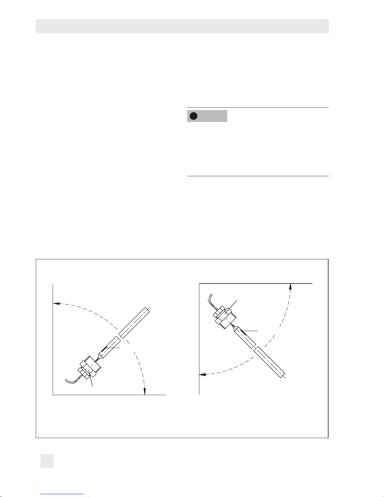
5.4.2 Installing the
temperature sensor
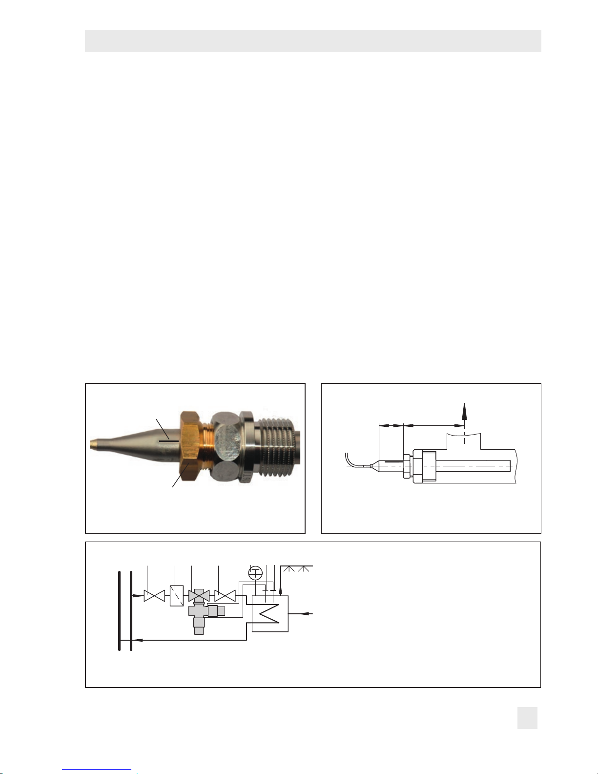
Mounting position
The mounting position of the temperature
sensor depends on the sensor version:
Sensor in horizontal position or with sensor
tip pointing up · Marked by an embossed
'o' on the screw gland.
To help align the sensor in the horizontal position, a marking bead (see Fig.6) is located
on the sensor. This marking must face upward.
Marking bead
Screw gland
Fig.6: Sensor with marking bead
Approx.
10 mm
Max.
60 mm
Fig.7: Process medium owing over the
sensor
1123 546
1 Shut-off valve
2 Strainer
3 Temperature regulator
4 Thermometer
5 Temperature sensor TR
6 Temperature sensor STM
Fig.8: Sample installation·TR/STM on a water-heated boiler
Page 22
22 EB 2183 EN
Mounting and start-up
Sensor in horizontal position or with sensor
tip pointing down · Marked by an embossed
'u' on the screw gland.
To help align the sensor in the horizontal position, a marking bead (see Fig.9) is located
on the sensor. This marking must face upward.
The screw gland seals off the sensor.
Î Weld a welding socket with G½ female
thread at the place of installation.
Î Make sure that almost all of the process
medium being monitored ows around
the sensor (of Type2403). See sectionFig.7.
Î It must be installed in a location where
overheating or considerable idling times
cannot occur.
Capillary tube
Î Carefully run the capillary tube (8) with-
out bending or twisting it. Make sure that
the capillary tube is not damaged.
Risk of capillary tube damage due to incorrect handling.
− Do not shorten the capillary tube.
− Roll up excess tube to form a ring. The
smallest bending radius is 50mm.
− Observe the permissible ambient tem-
perature of max. 50°C over the entire
length of the capillary tube.
NOTICE
!
'o' marking 'u' marking
U
O
'o' marking
'u' marking
Marking bead
Marking bead
Tip of sensor in horizontal position or pointing
up, with intermediate positions
Tip of sensor in horizontal position or pointing
down, with intermediate positions
Fig.9: Installing the temperature sensor (vapor pressure)
Page 23

EB 2183 EN 23
Mounting and start-up
5.5 Start-up
Fill the plant very slowly with the process medium on start-up.
Risk of burn injuries due to hot or cold components and pipelines.
Depending on the process medium, valve
components and pipelines may get very hot
or cold and cause burn injuries.
− Allow components and pipelines to cool
down or heat up.
− Wear protective clothing and safety gloves.
Malfunction and damage due to adverse effects of weather conditions (temperature, humidity).
Do not install the safety temperature monitor
outdoors or in rooms prone to frost. If such a
location cannot be avoided, protect the regulator against freezing up if the process me-
dium owing through the valve can freeze
up. Either heat the regulator or remove it
from the plant and completely drain the residual medium.
Risk of the valve being destroyed by steam
hammering.
− Drain off any condensate in the pipeline.
− Vent the plant.
WARNING
!
NOTICE
!
NOTICE
!
Î Fill the plant very slowly with the process
medium on start-up.
Once the safety temperature monitor is
mounted onto the valve, it can be put into
operation.
5.5.1 Gases and liquids
Î Open the shut-off valves slowly prefera-
bly starting from the upstream pressure
side.
Î Avoid pressure surges.
5.5.2 Steam
Î Completely drain and dry steam lines to
prevent water hammering.
Î Slowly allow the steam to enter the plant
to ensure that the pipes and valves warm
up evenly and to avoid excessive ow
velocities.
Î Before the full capacity is reached, drain
off the start-up condensate.
Î Make sure that the air contained in the
plant escapes as quickly as possible.
Î Open the shut-off valves slowly prefera-
bly starting from the upstream pressure
side.
Î Avoid pressure surges.
Page 24
24 EB 2183 EN
Operation
6 Operation
See Fig.2.
6.1 Adjusting the limit
temperature
1. If necessary, unscrew the Type2430
Control Thermostat.
2. Set the target limit temperature by turn-
ing the black adjustment knob (12, see
Fig.2) according to the scale (see Table4).
Turn the adjustment knob clockwise ()
to reduce the limit temperature.
Turn the adjustment knob counterclock-
wise () to increase the limit temperature.
3. Pull the wire through the lead-seal hole
(13) and lead-seal it to x the adjusted
limit.
4. Mount the Type2430 Control Thermostat
onto the valve (see section5.3).
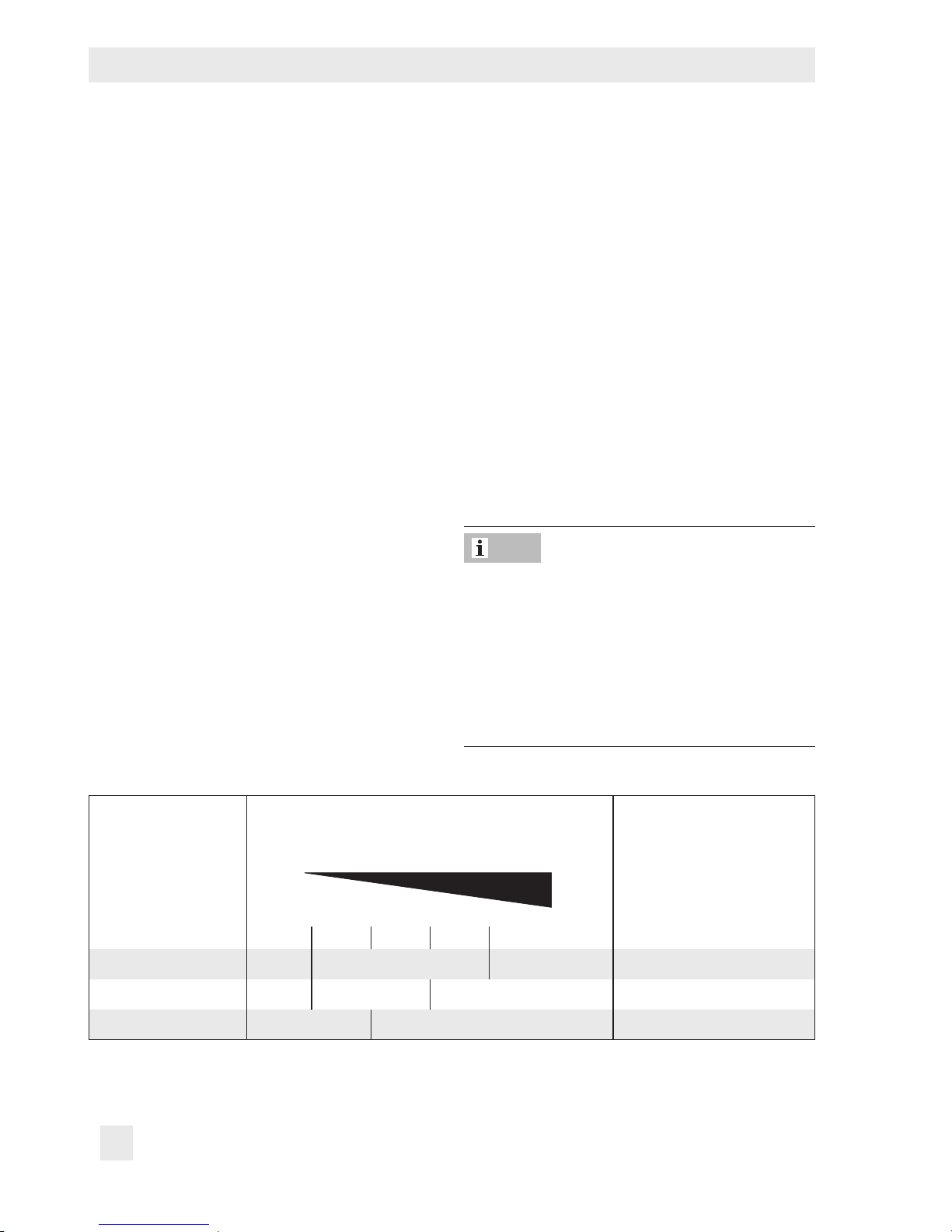
The limit temperature is continuously adjust-
able.
The limit can be changed roughly by turning
the adjuster according to the specications
(limit change per turn). After reaching the
limit temperature, the Type2403 Safety Temperature Monitor must close the valve completely (leakage rate 0.05% of the K
VS
coef-
cient).
When the Type2403 Safety Temperature
Monitor is combined with a Type2430 Con-
trol Thermostat, make sure that there is a
minimum difference of approximately +15K
between the adjusted limit temperature of the
safety temperature monitor and the set point
temperature of the control thermostat.
Note
Table4: Rough limit adjustment
1)
Limit value range Scale intervals Limit change per turn
01 2
3
4
Approx.
60 to 75°C 60°C 75°C 2.6°C
75 to 100°C 75°C 100°C 2.2°C
100 to 120°C 100°C 120°C 2.4°C
1)
Precise adjustment is only possible using a thermometer (see section6.2).
Page 25
EB 2183 EN 25
Operation
6.2 Fine adjustment of the limit
temperature
Risk of bursting in pressure equipment.
Valves and pipelines are pressure equipment. Improper opening can lead to valve
components bursting.
− Before starting any work on the valve, de-
pressurize all plant sections concerned as
well as the valve.
− Drain the process medium from all the
plant sections concerned as well as the
valve.
− Wear personal protective equipment.
Risk of personal injury due to residual process medium in the valve.
While working on the valve, residual process
medium can escape and, depending on its
properties, may lead to personal injury, e.g.
(chemical) burns.
− If possible, drain the process medium from
all the plant sections concerned and the
valve.
− Wear protective clothing, safety gloves and
eyewear.
Risk of burn injuries due to hot or cold components and pipelines.
Depending on the process medium, valve
components and pipelines may get very hot
or cold and cause burn injuries.
DANGER
!
WARNING
!
WARNING
!
− Allow components and pipelines to cool
down or heat up.
− Wear protective clothing and safety gloves.
In case you want to make ne adjustments to
the safety temperature monitor or the limit
value deviates, proceed as follows:
Fine adjustment using a thermometer
installed in the plant
1. Adjust the limit temperature of the safety
temperature monitor to approx. 10K below the required limit (see section6.1).
2. When a control thermostat is mounted
on the safety temperature monitor, adjust
the limit temperature to approx. 10°C
above the limit temperature.
3. Read the resulting temperature at the
thermometer installed in the plant (after
approx. 5min.).
4. When the limit temperature is still too
low:
slowly turn the rotary knob (12) at the
safety temperature monitor clockwise to
increase the limit until the temperature at
the thermometer reaches and remains at
the limit temperature.
After the temperature reaches the limit
temperature:
turn the rotary knob clockwise () one
more turn.
5. When a control thermostat is mounted,
readjust it to the required set point.
Page 26

26 EB 2183 EN
Servicing
7.1 Preparation for return shipment
Defective devices can be returned to
SAMSON for repair. Proceed as follows to
return devices to SAMSON:
1. Put the device out of operation. See sec-
tion9.
2. Decontaminate the valve. Remove any
residual process medium.
3. Fill in the Declaration on Contamination,
which can be downloaded from our
website at uwww.samson.de > Services
> Check lists for after sales service >
Declaration on Contamination.
4. Send the device together with the lled-in
form to your nearest SAMSON subsidiary. SAMSON subsidiaries are listed on
our website at uwww.samson.de >
Contact.
7 Servicing
The safety temperature monitor does not require any maintenance. Nevertheless, it is
subject to natural wear, particularly at the
soldered joints.
The device was checked by SAMSON before
it left the factory.
− The product warranty becomes void if ser-
vice or repair work not described in these
instructions is performed without prior
agreement by SAMSON's After-sales Service department.
− Only use original spare parts by
SAMSON, which comply with the original
specications.
Note
Page 27
EB 2183 EN 27
Malfunctions
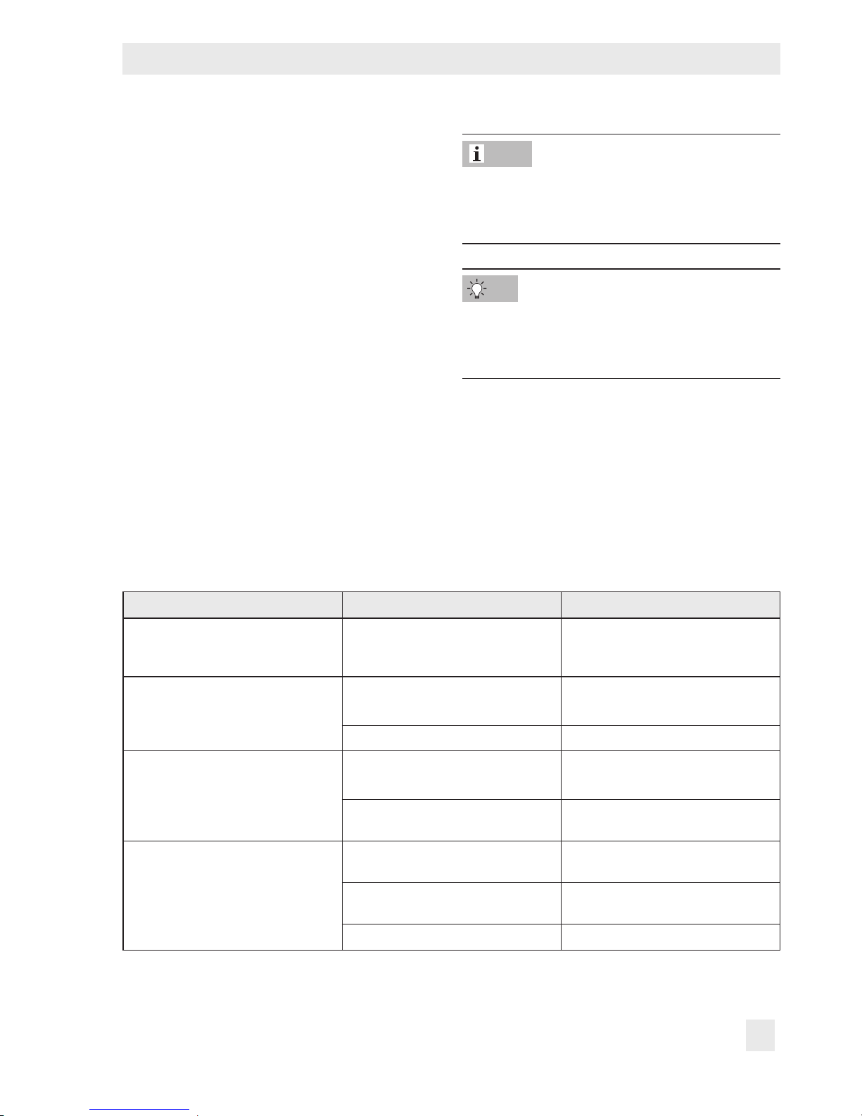
8 Malfunctions
The malfunctions listed in Table5 are caused
by mechanical faults and incorrect regulator
sizing. In the simplest case, the functioning
can be restored following the recommended
action. Special tools may be required for re-
pair work.
Depending on the operating conditions,
check the valve at certain intervals to prevent
possible failure before it can occur. Opera-
tors are responsible for drawing up an inspection plan.
Table5: Troubleshooting
Malfunction Possible reasons Recommended action
The temperature adjusted at the
control thermostat reaches the
adjusted limit temperature.
Control thermostat defective Î Replace the control thermostat.
Temperature exceeds the adjusted
limit.
Foreign particles blocking the valve
plug
Î Remove foreign particles.
Î Replace damaged parts.
Valve trim is worn. Î Replace damaged parts.
Increased ow through closed valve
(seat leakage)
Foreign particles blocking the valve
plug
Î Remove foreign particles.
Î Replace damaged parts.
Valve trim, particularly with soft seat,
is worn.
Î Replace damaged parts.
Heat supply has been interrupted.
STM is defective and has moved to
the fail-safe position.
Î Replace the STM.
Temperature sensor not correctly
installed.
Î Check installation. Observe notes
on installation (see section5.4).
Strainer blocked Î Clean strainer.
Contact SAMSON's After-sales Service department for malfunctions not listed in the table.
SAMSON's After-sales Service department
can support you to draw up an inspection
plan for your plant.
Note
Tip
Page 28

28 EB 2183 EN
Decommissioning and disassembly
− Allow components and pipelines to cool
down or heat up.
− Wear protective clothing and safety gloves.
9.1 Decommissioning
To decommission the safety temperature
monitor before removing it, proceed as follows:
1. Close the shut-off valve on the upstream
side of the valve.
2. Close the shut-off valve on the down-
stream side of the valve.
3. Completely drain the pipelines and
valve.
4. Depressurize the plant. Shut off or dis-
connect the control line, if installed.
5. If necessary, allow the pipeline and de-
vice to cool down or heat up.
6. Remove the sensor from the pipeline
and, if necessary, seal the opening.
7. Remove the safety temperature monitor
from the valve.
9.2 Disposal
Î Observe local, national and internation-
al refuse regulations.
Î Do not dispose of components, lubricants
and hazardous substances together with
your household waste.
9 Decommissioning and
disassembly
Risk of bursting in pressure equipment.
Valves and pipelines are pressure equipment. Improper opening can lead to valve
components bursting.
− Before starting any work on the valve, de-
pressurize all plant sections concerned as
well as the valve.
− Drain the process medium from all the
plant sections concerned as well as the
valve.
− Wear personal protective equipment.
Risk of personal injury due to residual process medium in the valve.
While working on the valve, residual process
medium can escape and, depending on its
properties, may lead to personal injury, e.g.
(chemical) burns.
− If possible, drain the process medium from
all the plant sections concerned and the
valve.
− Wear protective clothing, safety gloves and
eyewear.
Risk of burn injuries due to hot or cold components and pipelines.
Depending on the process medium, valve
components and pipelines may get very hot
or cold and cause burn injuries.
DANGER
!
WARNING
!
WARNING
!
Page 29

EB 2183 EN 29
Appendix
10 Appendix
10.1 After-sales service and
spare parts
After-sales service
Contact SAMSON's After-sales Service de-
partment for support concerning service or
repair work or when malfunctions or defects
arise.
E-mail
You can reach the After-sales Service De-
partment at aftersalesservice@samson.de.
Addresses of SAMSONAG and its subsidiaries
The addresses of SAMSON AG, its
subsidiaries, representatives and service
facilities worldwide can be found on the
SAMSON website (uwww.samson.de) or in
all SAMSON product catalogs.
Required specications
Please submit the following details:
− Order number and position number in
the order
− Type and nominal size (valve)
− Conguration ID (Type2403 STM)
− Conguration ID (Type2430 TR)
− Limit value range
− Temperature and process medium
− Is a strainer installed?
− Installation drawing showing the exact
location of the regulator and all the
additionally installed components
(Type2430 Control Thermostat, shut-off
valves, pressure gauge, etc.)
Spare parts
There are no spare parts available for the
safety temperature monitor.
10.2 Certicates
The EU declarations of conformity are in-
cluded on the next pages.
Page 30

30 EB 2183 EN
SAMSON AKTIENGESELLSCHAFT
Weismüllerstraße 3 60314 Frankfurt am Main
Telefon: 069 4009-0 · T elefax: 069 4009-1 507
E-Mail: samson@sams on.de
Revision 03
Modul D/Module D, Nr./No. / N° CE-0062-PED-D-SAM 001-16-DEU-rev-A
SAMSON erklärt in alleiniger Verantwortung für folgende Produkte:/For the following products, SAMSON hereby declares
under its sole responsibility:
Sicherheitstemperaturbegrenzer STB 2403 (2750-5)/Safety Temperature Monitor STM 2403 (2750-5)
in Kombination mit Ventilen/combined with valves
2431, 2432, 2433, 2435, 2436, 2437, 2479, 2488 (2710, 2720, 2730)
die Konformität mit nachfolgender Anforderung/the conformity with the following requirement.
Richtlinie des Europäischen Parlaments und des Rates zur
Harmonisierung der Rechtsvorschriften der Mitgliedstaaten über die
Bereitstellung von Druckgeräten auf dem Markt.
2014/68/EU vom 15.05.2014
Directive of the European Parliament and of the Council on the
harmonization of the laws of the Member States relating of the making
available on the market of pressure equipment.
2014/68/EU of 15 May 2014
EG-Baumusterprüfbescheinigung
EC Type Examination Certificate
Modul B
Module B
Zertifikat-Nr./Certificate no.
01 202 931-B-12-0009
Angewandtes Konformitätsbewertungsverfahren
Conformity assessment procedure applied
Modul D
Module D
Zertifikat-Nr./Certificate no.
CE-0062-PED-D-SAM-001-16-DEU-rev-A
Dem Entwurf zu Grunde gelegt sind Verfahren aus:/The design is based on the procedures specified in the following standards:
DIN EN 12516-2, DIN EN 12516-3 bzw./or ASME B16.1, ASME B16.24, ASME B16.42
Das Qualitätssicherungssystem des Herstellers wird von folgender benannter Stelle überwacht:
The manufacturer’s quality management system is monitored by the following notified body:
Bureau Veritas S.A. Nr./No. 0062, Newtime, 52 Boulevard du Parc, IIle de la Jatte, 92200 Neuilly sur Seine, France
Hersteller:/Manufacturer: SAMSON AG, Weismüllerstraße 3, 60314 Frankfurt am Main, Germany
Frankfurt am Main, 08. Februar 2017/08 February 2017
Klaus Hörschken Dr. Michael Heß
Zentralabteilungsleiter/Head of Central Department Zentralabteilungsleiter/Head of Central Department
Entwicklung Ventile und Antriebe/R&D, Valves and Actuators Product Management & Technical Sales
EU
-Konformitaetserklaerung_ Blatt-16_Modul-B_und_Modul-D_DE-EN_Rev.03_2017-02-08.docx
Page 31

EB 2183 EN 31
SAMSON AKTIENGESELLSCHAFT
Weismüllerstraße 3 60314 Frankfurt am Main
Telefon: 069 4009-0 · T elefax: 069 4009-1 507
E-Mail: samson@sams on.de
Revision 03
Modul H/Module H, Nr./No. / N° CE-0062-PED-H-SAM 001-16-DEU-rev-A
SAMSON erklärt in alleiniger Verantwortung für folgende Produkte:/For the following products, SAMSON hereby declares
under its sole responsibility:
Ventile für Temperaturregler/Valves for temperature regulators
Typ/Type 2111, 2121, 2431, 2432, 2435, 2436, 2437 (Erz.-Nr./Model No. 2710), 2433, 2118 (2713), 2119 (2803), 2111, 2121 (2811), 2114
(2814)
die Konformität mit nachfolgender Anforderung/the conformity with the following requirement.
Richtlinie des Europäischen Parlaments und des Rates zur Harmonisierung der Rechtsvorschriften
der Mitgliedstaaten über die Bereitstellung von Druckgeräten auf dem Markt.
2014/68/EU vom 15. 05.2014
Directive of the European Parliament and of the Council on the harmonization of the laws of the
Member States relating of the making available on the market of pressure equipment.
2014/68/EU of 15 May 2014
Angewandtes Konformitätsbewertungsverfahren für Fluide nach Art. 4(1)(c.ii) und (c.i) zweiter
Gedankenstrich.
Modul siehe
Tabelle
durch
certified by
Bureau Veritas
S. A. (0062)
Conformity assessment procedure applied for fluids according to Artic le 4(1)(c.ii) and (c.i), second
indent
See table for
module
Nenndruck
Pressure rating
DN
NPS
15½ 20¾ 251 321¼40
1½ 502
65
803 1004 125
1506 2008 250
10
PN 16 ohne/without
(1)
A
(2)(3)
H
PN 25 ohne/without
(1)
A
(2)(3)
H
PN 40 ohne/without
(1)
A
(2)(3)
H
Class 150 ohne/without
(1)
A
(2)(3)
H
Class 300 ohne/without
(1)
A
(2)(3)
H
(1) Das auf dem Stellgerät aufgebrachte CE-Zeichen hat keine Gültigkeit im Sinne der Druckgeräterichtlinie.
The CE marking affixed to the control valve is not valid in the sense oft the Pressure Equipment Directive.
(2) Das auf dem Stellgerät aufgebrachte CE-Zeichen gilt ohne Bezeichnung der benannten Stelle (Kenn-Nr. 0062).
The CE marking affixed to the control valve is valid without specifying the notified body (ID number 0062).
(3) Die Identifikationsnummer 0062 von Bureau Veritas S.A. gilt nicht für Modul A.
The identification number 0062 of Bureau Veritas S.A. is not valid for Modul A.
Geräte, denen laut Tabelle das Konformitätsbewertungsverfahren Modul H zugrunde liegt, beziehen sich auf die
„Zulassungsbescheinigung eines Qualitätssic herungssystems“ ausgestellt durch die Notifizierte Stelle.
Devices whose conformity has been assessed based on Module H refer to the certificate of approval for the quality management system
issued by the notified body
.
Dem Entwurf zu Grunde gelegt sind Verfahren aus:/The design is based on the procedures specified in the following standards:
DIN EN 12516-2, DIN EN 12516-3 bzw./or ASME B16.1, ASME B16.24, ASME B16.34, ASME B16.42
Das Qualitätssicherungssystem des Herstellers wird von folgender benannter Stelle überwacht
The manufacturer’s quality management system is monitored by the following notified body:
Bureau Veritas S.A. Nr./No. 0062, Newtime, 52 Boulevard du Parc, IIle de la Jatte, 92200 Neuilly sur Seine, France
Hersteller:/Manufacturer: SAMSON AG, Weismüllerstraße 3, 60314 Frankfurt am Main, Germany
Frankfurt am Main, 08. Februar 2017/08 February 2017
Klaus Hörschken Dr. Michael Heß
Zentralabteilungsleiter/Head of Central Department Zentralabteilungsleiter/Head of Central Department
Entwicklung Ventile und Antriebe/R&D, Valves and Actuators Product Management & Technical Sales
EU
-Konformitaetserklaerung_ Blatt-05_Modul-A_Modul-H_DE-EN_Rev.03_2017-02-08.docx
Page 32

SAMSON AG · MESS- UND REGELTECHNIK
Weismüllerstraße 3 · 60314 Frankfurt am Main, Germany
Phone: +49 69 4009-0 · Fax: +49 69 4009-1507
samson@samson.de · www.samson.de
EB 2183 EN
2018-06-20 · English
 Loading...