

Page 1
Mounting and
Operating Instructions
EB 2595 EN
Edition November 2014
Accessories
Compensation chamber for
Type41-23 (2412/2413) and Type41-73 (2417/2413) Regulators
as well as
Type2424, Type2425, Type2426, Type2427 and Type2429 Actuators
Page 2

SAMSON AG · MESS- UND REGELTECHNIK
Weismüllerstraße 3 · 60314 Frankfurt am Main, Germany
Phone: +49 69 4009-0 · Fax: +49 69 4009-1507
samson@samson.de · www.samson.de
EB 2595 EN
2015-08-18 · English
3 Operation
Proceed as follows:
− Unscrew the ller plug on the chamber
and undo the vent screw on the diaphragm actuator.
− For applications with steam: use the sup-
plied plastic funnel or a watering can to
ll the chamber with water until it overows at the vent hole on the actuator.
For applications with other liquids, ll the
compensation chamber with the process medium.
− Screw the ller plug back on the cham-
ber and tighten.
1 Application
A compensation chamber is installed in the
control line together with the listed regulators
and actuators. The liquid lled in the chamber (water for steam control) acts as a buffer
for process medium temperatures above
150°C and for steam. It prevents any hot
process medium coming into direct contact
with the actuator diaphragm and damaging
it.
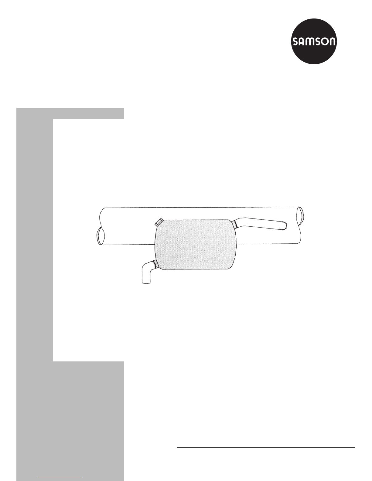
2 Installation
Install the compensation chamber at the
highest point of the control line. Make sure
that the control line between the diaphragm
chamber and compensation chamber as well
as between the pipeline and the compensation chamber inclines downwards at a ratio
of at least 1:10.
Connect the control line at the side of the
pipeline transporting the process medium or
the manifold.
The mounting position of the chamber is indicated on the chamber by an adhesive label with an arrow as well as by the word
oben (top) impressed on the chamber. It is
imperative that the mounting position of the
chamber is observed to guarantee the safe
functioning of the regulator.
Weld the control line coming from the pressure tapping point to the R
3
/
8
socket of the
chamber.
 Loading...