

Page 1
Self-operated Pressure Regulators
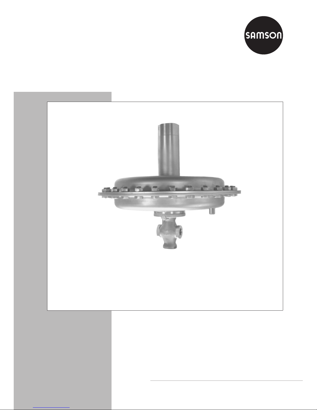
Excess Pressure Valve
Type 2408
Fig. 1· Type 2408 Excess Pressure Valve
Edition June 2010
Mounting and
Operating Instructions
EB 2528 EN
Page 2

Contents Page
1 Design and principle of operation . . . . . . . . . . . . . . . . . . . . . . 4
1.1 Process medium, application range, versions. . . . . . . . . . . . . . . . . 4
2 Installation . . . . . . . . . . . . . . . . . . . . . . . . . . . . . . . . . 4
2.1 Mounting position . . . . . . . . . . . . . . . . . . . . . . . . . . . . . . 4
2.2 Strainer. . . . . . . . . . . . . . . . . . . . . . . . . . . . . . . . . . . 6
2.3 Shut-off valve . . . . . . . . . . . . . . . . . . . . . . . . . . . . . . . . 6
2.4 Pressure gauge . . . . . . . . . . . . . . . . . . . . . . . . . . . . . . . 6
2.5 Control line . . . . . . . . . . . . . . . . . . . . . . . . . . . . . . . . . 6
3 Operation . . . . . . . . . . . . . . . . . . . . . . . . . . . . . . . . . 7
3.1 Start-up. . . . . . . . . . . . . . . . . . . . . . . . . . . . . . . . . . . 7
3.2 Adjusting the set point. . . . . . . . . . . . . . . . . . . . . . . . . . . . 7
3.3 Decommissioning . . . . . . . . . . . . . . . . . . . . . . . . . . . . . . 8
4 Maintenance and troubleshooting . . . . . . . . . . . . . . . . . . . . . . 8
4.1 Pressure fluctuations . . . . . . . . . . . . . . . . . . . . . . . . . . . . . 8
5 Nameplate . . . . . . . . . . . . . . . . . . . . . . . . . . . . . . . . . 9
6 Service . . . . . . . . . . . . . . . . . . . . . . . . . . . . . . . . . . . 9
7 Technical data. . . . . . . . . . . . . . . . . . . . . . . . . . . . . . . 10
8 Dimensions . . . . . . . . . . . . . . . . . . . . . . . . . . . . . . . . 11
2 EB 2528 EN
Contents
CAUTION!
Indicates a hazardous situation which, if not
avoided, could result in minor or moderate
injury.
NOTICE
Indicates a risk of property damage.
Note! Indicates supplementary explanations,
information and tips.
Definitions of the signal words used in these instructions
Page 3
EB 2528 EN 3
Safety instructions
General safety instructions
Observe the following instructions on installation, start-up and operation of the regulator for
your own safety:
4
The regulator is to be mounted, started up or serviced by fully trained and
qualified personnel only, observing the accepted industry codes and practices.
Make sure employees or third persons are not exposed to any danger.
All safety instructions and warnings in these mounting and operating
instructions, particularly those concerning assembly, start-up and
maintenance, must be observed.
4
According to these mounting and operating instructions, trained personnel is
referred to as individuals who are able to judge the work they are assigned to
and recognize possible dangers due to their specialized training, their
knowledge and experience as well as their knowledge of the applicable
standards.
4
The regulator fulfils the requirements of the European Pressure Equipment
Directive 97/23/EC.
4
For appropriate operation, make sure that the regulator is only used in areas
where the operating pressure and temperatures do not exceed the operating
values specified in the order that the valve sizing data are based on.
4
The manufacturer does not assume any responsibility for damage caused by
external forces or any other external influence!
4
Any hazards that could be caused in the regulator by the process medium, the
operating pressure or by moving parts are to be prevented by means of the
appropriate measures.
4
Proper shipping and storage are assumed.
Note! Non-electric valve versions whose bodies are not lined with an insulating material coat
ing do not have their own potential ignition source according to the risk assessment stipulated in
EN 13463-1:2001, section 5.2, even in the rare incident of an operating fault. Therefore, such
valve versions do not fall within the scope of Directive 94/9/EC.
Page 4

1 Design and principle of opera
-
tion
See also Fig. 2, page 5.
The process medium flows through the valve
in the direction indicated by the arrow on the
body. The position of the valve plug (3) deter
mines the flow rate across the area released
between the valve's plug and seat (2).
In pressureless state (control line not con
nected or no pressure applied), the valve is
closed by theforce of the set point springs (7).
The upstream pressure p
1
to be controlled is
tapped upstream of the regulator. Using an
external control line, this pressure is transmitted to the tapped connection (9) on the actuator housing (6) where it is converted into a positioning force by the diaphragm plate with
operating diaphragm (5). This positioning
force is used to move the plug stem (4) and
thus the valve plug depending on the force of
the set point springs (7). The spring force can
be adjusted on the set point adjuster (8).
When the force resulting from the upstream
pressure p
1
exceeds the adjusted set point,
the valve opens proportionally to the change
in pressure.
1.1 Process medium, application
range, versions
Excess pressure valve for set points between
5 mbar to 1000 mbar for gases at tempera
tures from –20 to +60 °C.
Valves with flanged body in DN 15 and
DN 25 as well as with G ½, G ¾ and G1fe
male thread.
2 Installation
See also Fig. 2, page 5.
NOTICE
Install a strainer (e.g. SAMSON Type 2 NI)
upstream of the regulator (refer to sec
tion 2.2).
Make sure the regulator is mounted free of
stress. If necessary, support the piping near
the connecting flanges. Never attach supports
directly to the valve or actuator.
2.1 Mounting position
Mounting position (preferable)
– Install the regulator in a
horizontal pipeline with the
actuator housing and set
point adjuster pointing vertically up,
– The direction of flow must correspond to
the arrow on the body,
– Install the control line with a downward
slope of approx. 10 % towards the tapping
point to allow condensed liquid to flow
back into the tank or pipeline.
Other mounting positions
–
Install the regulator in a
vertical pipeline with the
actuator housing and set
point adjuster pointing to
the side.
Note! Higher system deviations may occur in
this mounting position.
–
Make sure the direction of flow matches the
arrow on the body (from bottom to top).
4 EB 2528 EN
Design and principle of operation
Page 5

EB 2528 EN 5
Installation
1 Valve body
2 Seat
3 Plug
4 Plug stem
5 Diaphragm plate with operating diaphragm
6 Actuator housing
7 Set point spring
8 Set point adjuster
9 Control line connection (G ¼ tapped connection for upstream pressure p
1
)
10 Cap
10
Fig. 2 · Design and principle of operation, Type 2408 Excess Pressure Valve
Page 6

2.2 Strainer
Install a strainer upstream of the regulator
(Fig. 3). Install the strainer with the direction
of flow matching the arrow on the body.
Make sure the filter element is vertically sus
pended. Remember to leave enough space to
remove it.
2.3 Shut-off valve
Install a hand-operated shut-off valve both
upstream of the strainer and downstream of
the regulator (Fig. 3) to be able to shut down
the plant for cleaning and maintenance, and
when the plant is not used for longer periods
of time.
2.4 Pressure gauge
To monitor the pressures in the plant, install a
pressure gauge both upstream and down
-
stream of the regulator (Fig. 3).
2.5 Control line
G ¼ tapped connection (9) at the actuator
housing. Install a control line with at least
6 mm inside diameter on site, preferably an
8x1mmpipe made ofsteel or stainless steel.
Always attach the control line connection for
pressure tapping directly to the tank or vessel
as the medium is fully expanded and free of
turbulence at this point.
6 EB 2528 EN
Installation
Fig. 3 · Sample installation
min.
2 x DN
min. 5 x DN
DN
241
p
1
p2
1
3
2
4
1
p
1 p2
1
4
3
2
min.
3 x DN
Type 2408
Type 2408
≈
10 % slope towards
pressure tapping
point
≈
10 % slope towards
pressure tapping
point
1 Shut-off valve
2 Pressure gauge (upstream pressure)
3 Strainer
4 Pressure gauge (downstream pressure)
Page 7

When tapping the pressure at a straight pipe
line section, observe a minimum distance of
at least twice the nominal valve size to the
regulator.
Connect the control lines to the side or top of
the main horizontal pipeline. If possible, in
stall the tapping connection in a pipe expan
sion.
Install other fittings that maycause flow turbu
lence (e.g. shut-off valves, restrictions, bows,
bends or branches) at an appropriate dis
tance to the control line connection (at least
three times the nominal valve size).
Note! If the gas to be controlled contains
moisture, condensate may form in the control
line, which can damage the regulator. To allow the gas to flow back into the tank or pipeline, install the control line with a downward
slope of approx. 10 % towards the pressure
tapping point.
3 Operation
3.1 Start-up
See also Fig. 2, page 5.
NOTICE
Do not start up the regulator before all com
ponents have been installed.
Make sure the control line is free of dirt or
other contaminations that may impair the
proper medium flow.
Connect the line properly.
We recommend to open shut-off valves
slowly from the downstream side. Avoid
pressure surges.
NOTICE
The max. permissible pressure at the operat
-
ing diaphragm must not exceed 0.5 bar with
A = 1200 cm², 1 bar with A = 640 cm²,
2 bar with A = 320 cm² and 4 bar with A =
160 cm².
Make sure this pressure is not exceeded, par
ticularly when pressure-testing the plant with
the regulator installed or when starting up the
plant.
3.2 Adjusting the set point
Adjust the desired set point by tensioning the
set point springs using the set point adjuster
(SW 27/¾" adjustment screw).
4
Remove the cap (10).
4
Turn the adjustment screw using a socket
wrench with width across flats SW 27.
4
Turn the adjuster clockwise P to increase
the set point and counterclockwise
Q to
reduce it.
4
Remount the cap.
EB 2528 EN 7
Operation
Fig. 4 · Set point adjustment; view from top
Adjustment screw
SW 27 (¾")
Page 8

Check the adjusted set point on the pressure
gauge installed upstream of the regulator
(Fig. 3).
3.3 Decommissioning
We recommend to close the upstream shut-off
valve before closing the shut-off valve in
-
stalled downstream of the regulator.
4 Maintenance and trouble
-
shooting
The pressure regulator is maintenance free.
Nevertheless, it is subject to natural wear,
particularly at the seat, plug and operating
diaphragm.
Depending on the operating conditions, the
regulator needs to be checked at regular intervals to detect and remove possible malfunctions.
CAUTION!
For installation and maintenance work on the
regulator, make sure the relevant plant sec
tion has been depressurized and, depending
on the process medium, drained as well. We
recommend to remove the regulator from the
pipeline.
If necessary, allow the regulator to cool down
to reach ambient temperature before starting
any work on it.
Disconnect or shut off the control line to avoid
any hazards that could be caused by moving
regulator parts.
As valves are not free of cavities, remember
that residual process medium might still be
contained in the valve.
4.1 Pressure fluctuations
NOTICE
Pressure fluctuations (oscillation) may dam
-
age the regulator and plant. As a result, pre
vent them from occurring or remove their
cause immediately.
To stop oscillation from occurring, the follow
ing actions may be helpful:
4
Check the pressure tapping point at the
control line (refer to section 2.5); if neces
-
sary, move the tapping point.
4
Screw a SAMSON restriction into the
sleeve for the tapped connection (9): order no. 1991-7114 for 1200 and
640 cm², order no. 1991-7113 for 320
and 160 cm².
4
Check the regulator's sizing data. If necessary, change the K
VS
coefficient, seat di-
ameter or diaphragm area.
Contact SAMSON (refer to section 6) if the
problems persist.
8 EB 2528 EN
Maintenance and troubleshooting
Page 9

5 Nameplate
6 Service
If malfunctions or defects occur, contact the
SAMSON After-sales Service for support.
The addresses of SAMSON AG, its subsidiaries, representatives and service facilities
worldwide can be found on the Internet at
www.samson.de, in a SAMSON product cat
alog or on the back of these mounting and
operating instructions.
Include the following details when making in
quiries:
4
Type and nominal size of the regulator
4
Configuration ID (Var-ID)
4
Upstream and downstream pressures
4
Temperature and process medium
4
Min. und max. flow rates
4
Has a strainer been installed?
4
Installation drawing indicating the exact
location of the regulator and all additionally mounted units (shut-off valves, pressure gauges etc.)
EB 2528 EN 9
Nameplate
Fig. 5 · Nameplate
Legend
1 Configuration ID (VAR-ID)
2 Manufacturing data
3 Type designation (2408)
4 Max. perm. differential pressure
in bar
5 Max. perm. temperature in °C
6 Nominal size DN or connection
thread G
7KVScoefficient
8 Set point range in bar
9 Nominal pressure PN
1
2
4
6
9
SAMSON
7
8
3 5
Page 10

7 Technical data
10 EB 2528 EN
Technical data
Table 1 · Technical data
Connection · Nominal size G ½, G ¾ and G 1
Stainless steel
DN 15 and DN 25
Spheroidal graphite iron
Nominal pressure PN 25
Control line connection for
8 x 1 mm pipe
G ¼
K
VS
coefficients 0.25 · 1.0 · 2.5 · 3.21)· 5.0
1)
Max. perm. differential pressureΔp 6 bar
Max. perm. pressure at the actuator
Actuator area A = 1200 cm²
Actuator area A = 640 cm²
Actuator area A = 320 cm²
Actuator area A = 160 cm²
0.5 bar
1 bar
2 bar
4 bar
Permissible temperature range of the
medium
–20 to +60 °C
Leakage class acc. to DIN EN 60534-4 Soft seal, at least class IV
Set point ranges
5 to 15 mbar · 10 to 30 mbar · 25 to 60 mbar · 50 to 200 mbar
100 to 1000 mbar
1)
Only in conjunction with 100 to 1000 mbar set point range
Page 11

8 Dimensions
EB 2528 EN 11
Dimensions
Fig. 6 · Dimensions
Flanged body made of
spheroidal graphite iron
Body with screwed ends
made of stainless steel
Table 2 · Dimensions in mm
Connection G ½ G ¾ G 1 DN 15 DN 25
Female thread ½” ¾” 1” – –
Length L 65 75 90 130 160
Width across flats SW 34 34 46 – –
Height H3 45
5 to
15 mbar
Height H 360
Actuator Actuator Ø D = 490 mm, actuator area A = 1200 cm²
10 to
30 mbar
Height H 360
Actuator Actuator Ø D = 380 mm, actuator area A = 640 cm²
25 to 60 mbar
Height H 360
Actuator Actuator Ø D = 285 mm, actuator area A = 320 cm²
50 to 200 mbar
Height H 360
Actuator Actuator Ø D = 285 mm, actuator area A = 320 cm²
100 to 100 mbar
Height H 360
Actuator Actuator Ø D = 225 mm, actuator area A = 160 cm²
Approx. weight
in kg
5 to 60 mbar set point range 15.5 15.7 15.9 17 18
50 to 1000 mbar set point range 12 12.2 12.4 13.5 14.5
Page 12

SAMSON AG · MESS- UND REGELTECHNIK
Weismüllerstraße 3 · 60314 Frankfurt am Main · Germany
Phone: +49 69 4009-0 · Fax: +49 69 4009-1507
Internet: http://www.samson.de
EB 2528 EN
S/Z 2010-08
Page 13

Conversion from chromate coating to iridescent passivation
We at SAMSON are converting the surface treatment of passivated steel parts in our
production. As a result, you may receive a device assembled from parts that have been subjected to different surface treatment methods. This means that the surfaces of some parts show different reections. Parts can have an iridescent yellow or silver color.
This has no effect on corrosion protection.
For further information, go to u www.samson.de/chrome-en.html
Conversion from chromate coating to
iridescent passivation
 Loading...