

Page 1
Mounting and
Operating Instructions
EB 2520 EN
Translation of original instructions
Edition June 2017
Self-operated Pressure Regulators
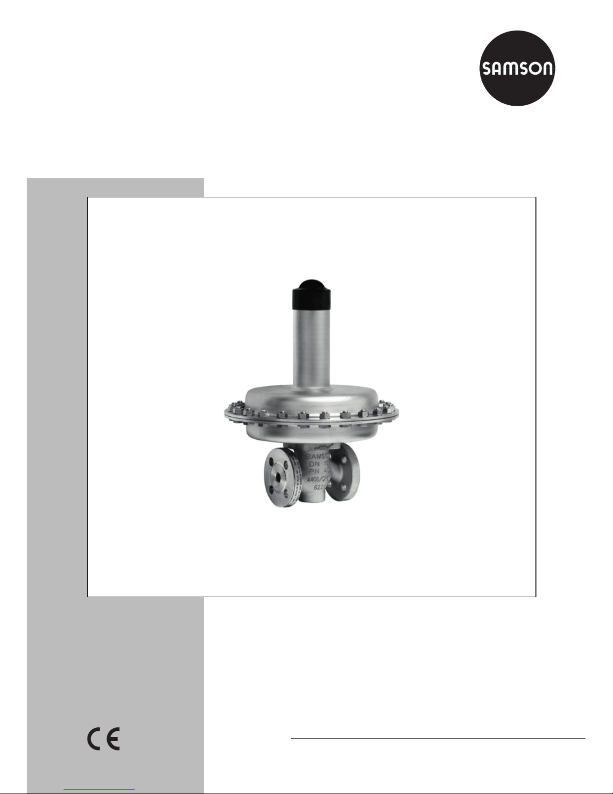
Type2405 Pressure Reducing Valve
Page 2
2 EB 2520 EN
Note on these mounting and operating instructions
These mounting and operating instructions assist you in mounting and operating the device
safely. The instructions are binding for handling SAMSON devices.
Î For the safe and proper use of these instructions, read them carefully and keep them for
later reference.
Î If you have any questions about these instructions, contact SAMSON‘s After-sales Service
Department (aftersalesservice@samson.de).
The mounting and operating instructions for the devices are included in
the scope of delivery. The latest documentation is available on our website
(www.samson.de) > Product documentation. You can enter the document
number or type number in the [Find:] eld to look for a document.
Denition of signal words
Hazardous situations which, if not avoided,
will result in death or serious injury
Hazardous situations which, if not avoided,
could result in death or serious injury
Property damage message or malfunction
Additional information
Recommended action
DANGER
!
WARNING
!
NOTICE
!
Note
Tip
Page 3

Contents
EB 2520 EN 3
1 Safety instructions and measures ...................................................................5
1.1 Notes on possible severe personal injury .........................................................7
1.2 Notes on possible personal injury ...................................................................7
1.3 Notes on possible property damage ................................................................8
2 Markings on the device .................................................................................9
3 Design and principle of operation ................................................................10
3.1 Versions ......................................................................................................11
3.2 Technical data .............................................................................................12
4 Measures for preparation ............................................................................16
4.1 Unpacking ..................................................................................................16
4.2 Transporting and lifting ................................................................................16
4.3 Storage .......................................................................................................16
4.4 Preparation for installation ............................................................................17
5 Mounting and start-up ................................................................................. 18
5.1 Installing the valve into the pipeline ...............................................................18
5.1.1 Installation conditions ...................................................................................18
5.1.2 Mounting position ........................................................................................18
5.1.3 Additional ttings .........................................................................................19
5.2 Quick check ................................................................................................20
5.3 Putting the regulator into operation ................................................................21
5.4 Adjusting the set point ..................................................................................21
6 Servicing.....................................................................................................22
6.1 Preparation for return shipment ..................................................................... 22
6.2 Ordering spare parts and operating supplies .................................................23
7 Malfunctions ...............................................................................................24
7.1 Troubleshooting ...........................................................................................24
8 Decommissioning and disassembly ..............................................................25
8.1 Decommissioning .........................................................................................25
8.2 Removing the valve from the pipeline .............................................................25
8.3 Disposal ......................................................................................................25
Page 4

4 EB 2520 EN
Contents
9 Annex.........................................................................................................26
9.1 After-sales service ........................................................................................26
9.2 Certicates ..................................................................................................26
Page 5

EB 2520 EN 5
Safety instructions and measures
1 Safety instructions and measures
Intended use
The Type2405 Pressure Reducing Valve is used to control the pressure of ammable gases
used as a source of energy, e.g. in boilers, driers, vaporizers, heat exchangers or industrial
ovens. Alternatively, it can control the compressed air supply in process engineering applications.
The device is designed to operate under exactly dened conditions (e.g. operating pressure,
process medium, temperature). Therefore, operators must ensure that the device is only used
in applications that meet the specications used for sizing the device at the ordering stage. In
case operators intend to use the device in other applications or conditions than specied,
contact SAMSON.
SAMSON does not assume any liability for damage resulting from the failure to use the de-
vice for its intended purpose or for damage caused by external forces or any other external
factors.
Î Refer to the technical data and nameplate for limits and elds of application as well as
possible uses.
Reasonably foreseeable misuse
The device is not suitable for use outside the limits dened during sizing and in the technical
data. Furthermore, the following activities do not comply with the intended use:
− Use as safety valve
− Use of non-original spare parts
− Performing service and repair work not described in these instructions
Qualications of operating personnel
The device must be mounted, started up, serviced, and repaired by fully trained and qualied personnel only; the accepted industry codes and practices are to be observed. According to these mounting and operating instructions, trained personnel refers to individuals who
are able to judge the work they are assigned to and recognize possible hazards due to their
specialized training, their knowledge and experience as well as their knowledge of the applicable standards.
Page 6

6 EB 2520 EN
Safety instructions and measures
Personal protective equipment
We recommend wearing the following protective equipment depending on the process medium:
− Protective clothing, gloves, and eyewear in applications with hot, cold, and/or corrosive
media
Î Check with the plant operator for details on further protective equipment.
Revisions and other modications
Revisions, conversions or other modications to the product are not authorized by SAMSON.
They are performed at the user's own risk and may lead to safety hazards, for example. Furthermore, the product may no longer meet the requirements for its intended use.
Warning against residual hazards
To avoid personal injury or property damage, operators and operating personnel must prevent hazards that could be caused in the device by the process medium and operating pressure by taking appropriate precautions. They must observe all hazard statements, warning
and caution notes in these mounting and operating instructions, especially for installation,
start-up, and service work.
Responsibilities of the operator
The operator is responsible for proper operation and compliance with the safety regulations.
Operators are obliged to provide these mounting and operating instructions as well as the
referenced documents to the operating personnel and to instruct them in proper operation.
Furthermore, the operator must ensure that operating personnel or third persons are not exposed to any danger.
Responsibilities of operating personnel
Operating personnel must read and understand these mounting and operating instructions as
well as the referenced documents and observe the hazard statements, warning and caution
notes specied in them. Furthermore, the operating personnel must be familiar with the applicable health, safety and accident prevention regulations and comply with them.
Referenced standards and regulations
The devices comply with the requirements of the European Pressure Equipment Directive
2014/68/EU. Devices with a CE marking have an EU declaration of conformity, which includes information about the applied conformity assessment procedure. This declaration of
conformity is included in the Appendix of these instructions (see section9.2).
Page 7

EB 2520 EN 7
Safety instructions and measures
Non-electric valve versions whose bodies are not lined with an insulating material coating do
not have their own potential ignition source according to the risk assessment stipulated in
EN13463-1:2009, section5.2, even in the rare incident of an operating fault. Therefore,
such valve versions do not fall within the scope of Directive 2014/34/EU.
Î For connection to the equipotential bonding system, observe the requirements specied in
section 6.4 of EN60079-14 (VDE0165 Part 1).
1.1 Notes on possible severe personal injury
DANGER
!
Risk of bursting in pressure equipment.
Control valves and pipelines are pressure equipment. Improper opening can lead to
valve components bursting.
Î Before starting any work on the control valve, depressurize all plant sections con-
cerned as well as the valve.
Î To prevent uncontrolled excess pressure, make sure that suitable overpressure pro-
tection is installed on site in the plant section.
Î Drain the process medium from all the plant sections concerned as well as the
valve.
Î Wear personal protective equipment.
1.2 Notes on possible personal injury
WARNING
!
Risk of personal injury due to residual process medium in the valve.
While working on the valve, residual process medium can escape and, depending on
its properties, may lead to personal injury, e.g. (chemical) burns.
Î If possible, drain the process medium from all the plant sections concerned and the
valve.
Î Wear protective clothing, safety gloves, and eyewear.
Page 8

8 EB 2520 EN
Safety instructions and measures
WARNING
!
Risk of burn injuries due to hot or cold components and pipelines.
Depending on the process medium, valve components, and pipelines may get very hot
or cold and cause burn injuries.
Î Allow components and pipelines to cool down or heat up.
Î Wear protective clothing and safety gloves.
Damage to health relating to the REACH regulation.
If a SAMSON device contains a substance which is listed as being a substance of very
high concern on the candidate list of the REACH regulation, this circumstance is indicated on the SAMSON delivery note.
Î Information on safe use of the part affected, see uhttp://www.samson.de/reach-
en.html.
1.3 Notes on possible property damage
NOTICE
!
Risk of valve damage due to contamination (e.g. solid particles) in the pipeline.
The plant operator is responsible for cleaning the pipelines in the plant.
Î Flush the pipelines before start-up.
Î Observe the maximum permissible pressure for valve and plant.
Risk of valve damage due to unsuitable medium properties.
The valve is designed for a process medium with dened properties.
Î Only use the process medium specied for sizing the valve.
Page 9
EB 2520 EN 9
Safety instructions and measures
NOTICE
!
Risk of leakage and valve damage due to excessively high or low tightening
torques.
Observe the specied torques on tightening valve components.
Excessively tightened torques lead to parts wearing out quicker. Parts that are too loose
may cause leakage.
Î Observe the specied tightening torques.
Risk of regulator damage due to incorrectly attached lifting equipment.
Î Do not attach lifting equipment to mounting parts (e.g. adjusting screw or control
line).
Conversion from chromate coating to iridescent passivation
We at SAMSON are converting the surface treatment of passivated steel parts in our production. As a result, you may receive a device assembled from parts that have been subjected to
different surface treatment methods. This means that the surfaces of some parts show different reections. Parts can have an iridescent yellow or silver color. This has no effect on corrosion protection. For further information go to uwww.samson.de/chrome-en.html.
Note
Page 10
10 EB 2520 EN
Markings on the device
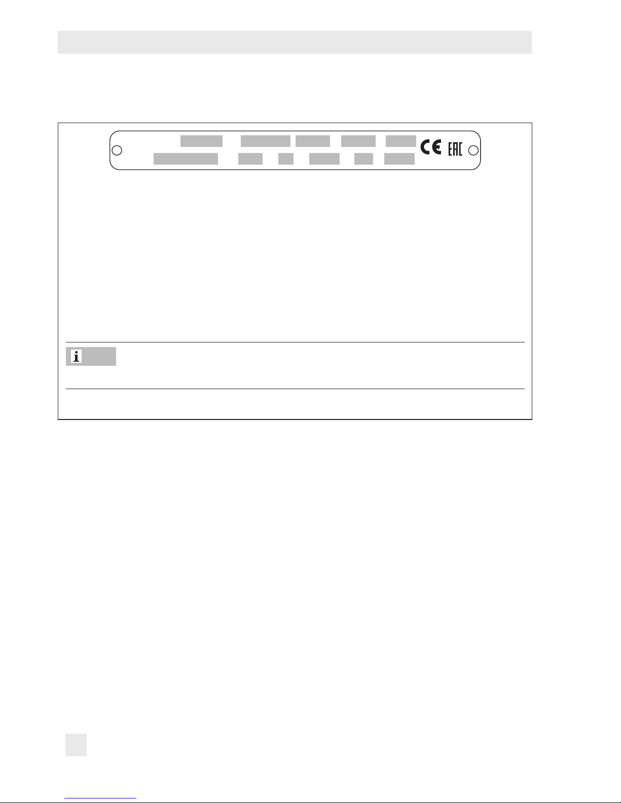
2 Markings on the device
SAMSON
4
6
231
7
89 11
5
10
Made in Germany
2009
xxxx
1 Type designation (2405)
2 Max. perm. operating pressure at the
actuator p
max
3 Conguration ID
4 Order number or date
5 K
VS
coefcient
7 Set point range/spring force
8 Nominal size
9 Nominal pressure
10 Permissible differential pressure (across
the valve)
11 Perm. temperature
12 Body material
The CE marking only exists for versions in nominal sizes DN32 to 50.
Fig.1: Nameplate
Note
Page 11

EB 2520 EN 11
Design and principle of operation
3 Design and principle of oper-
ation
The medium ows through the valve in the direction indicated by the arrow. The position
of the plug (3) determines the cross-sectional
area of ow between the plug and seat (2).
In the pressureless state (control line not connected and no pressure applied) the valve is
opened by the force of the set point springs
(7).
The downstream pressure p
2
to be controlled
is tapped downstream of the regulator and
transmitted over an external control line to
the control line connection (9) on the actuator housing (6) where it is converted into a
positioning force by the diaphragm plate
with operating diaphragm (5). This force is
used to move the plug stem (4) and the valve
plug depending on the force of the set point
springs. The spring force can be adjusted at
the set point adjuster (8).
When the force resulting from the downstream pressure p
2
rises above the spring
force adjusted at the set point springs, the
valve closes proportionally to the change in
pressure.
In the version with pressure balancing, the
forces produced by the upstream and downstream pressures acting on the plug are eliminated by the balancing diaphragm (10).
The plug is fully balanced.
p
1
p
2
8
7
6
5
11
4
9
1
3
2
Fig.2: Type2405 Pressure Reducing Valve without pressure balancing · KVS 1.6 to 4 · Flow-to-open
Page 12

12 EB 2520 EN
Markings on the device
p
1
p
2
p
1
p
2
10
1 Valve body
2 Seat
3 Plug
4 Plug stem
5 Diaphragm plate with operating
diaphragm
6 Actuator housing
7 Set point spring
8 Set point adjuster (screw SW27)
9 Control line connection, G¼ tting
10 Balancing diaphragm
11 Leakage line connection (special version),
G¼ tting
Fig.3: Type2405 Pressure Reducing Valve
without pressure balancing · K
VS
0.016 to 1 · Flow-to-close
Fig.4: Type2405 Pressure Reducing Valve with
pressure balancing · KVS 6.3 to 32
3.1 Versions
Type2405 Pressure Reducing Valve to control gases
Standard
− Temperature range from –20 to +60°C
− Set points from 5mbar to 10bar
− Nominal size DN15 to 50
− PN16 to 40
− Flanges
Options
− With pressure balancing (see Fig.4)
− Pressure tapping directly at the valve in-
stead of over an external control line
with 0.8 to 2.5bar, 2 to 5bar, and 4.5
to 10bar
− Temperature range from 0 to 150°C for
unbalanced versions with FKM diaphragm and FKM soft seal
Page 13

EB 2520 EN 13
Markings on the device
3.2 Technical data
Table1: Technical data
Nominal size DN15 DN20 DN25 DN32, 40, 50
Nominal pressure (valve)
PN16 · PN25 · PN40
K
VS
coefcients
Standard
4
6.3
8
32
Reduced K
VS
coefcients
0.016 · 0.04
0.1 · 0.25 · 0.4
1 · 1.6 · 2.5
0.016 · 0.04
0.1 · 0.25 · 0.4
1 · 1.6 · 2.5 · 4
0.016 · 0.04
0.1 · 0.25 · 0.4
1 · 1.6 · 2.5 · 4
6.3
1.6 · 2.5 · 4
6.3 · 8 · 16
20
Max. permissible differential pressure 10bar · 12bar
1)
Max. permissible temperature range
(medium temperature)
–20 to +60°C (0 to +150°C)
2)
Leakage class according to IEC60534-4 Soft-seated, minimum Class IV
Set point ranges
5 to 15mbar · 10 to 30mbar · 25 to 60mbar · 50 to 200mbar · 0.1 to
0.6bar · 0.2 to 1bar · 0.8 to 2.5bar · 2 to 5bar · 4.5 to 10bar
Max. perm.
pressure at
operating
diaphragm
1200cm² 0.5bar
640cm² 1bar
320cm² 2bar · 10bar
3)
160cm² 3bar · 16bar
3)
80cm² 5bar · 16bar
3)
40cm² · 2 to 5bar 10bar · 16bar
3)
40cm² · 4.5 to 10bar 15bar · 16bar
3)
Pressure
balancing
K
VS
=0.016 to 4 Without balancing diaphragm
K
VS
=6.3 to 32 With balancing diaphragm
Pressure tapping External
4)
Control line connection G ¼
1)
Version with set points from 0.1 to 10bar
2)
For unbalanced versions with FKM diaphragm and FKM soft seal
3)
Version with force limiter
4)
Special version with pressure tapping directly at the valve (see section3.1)
Page 14

14 EB 2520 EN
Markings on the device
Table2: Dimensions in mm
Nominal size DN15 DN20 DN25 DN32 DN40 DN50
Length L 130 150 160 180 200 230
Height H2
Forged steel 53 – 70 – 92 98
Other materials 44 72
Set point range
5 to 15mbar
Height H
Without balancing 325 370
With balancing 352 377
Actuator ØD = 490mm, A = 1200cm²
10 to 30mbar
Height H
Without balancing 318 366
With balancing 345 370
Actuator
ØD = 380mm,
A = 640cm²
ØD = 490mm,
A = 1200cm²
25 to 60mbar
Height H
Without balancing 318 366
With balancing 345 370
Actuator ØD=380mm, A=640cm²
50 to 200mbar
Height H
Without balancing 318 366
With balancing 345 370
Actuator ØD = 285mm, A = 320cm²
0.1 to 0.6bar
Height H
Without balancing 318 366
With balancing 345 370
Actuator ØD = 285mm, A = 320cm²
0.2 to 1bar
Height H
Without balancing 318 366
With balancing 345 370
Actuator ØD = 225mm, A = 160cm²
0.8 to 2.5bar
Height H
Without balancing 330 365
With balancing 356 369
Actuator ØD = 170mm, A = 80cm²
2 to 5bar
Height H
Without balancing 333 368mm
With balancing 359 373mm
Actuator ØD = 170mm, A = 40cm²
4.5 to 10bar
Height H
Without balancing 437 485
With balancing 463 489
Actuator ØD = 170mm, A = 40cm²
Page 15

EB 2520 EN 15
Markings on the device
Dimensional drawings
DN15 to 25 DN32 to 50
H
ØD
H2
H
ØD
L
L
H2
Control line connection G¼, for A = 40, 80,
160, and 320cm²
Control line connection G ¼, for A = 640 and
1200cm²
The control line connection is turned by 90° in the drawing. The connection is normally located
opposite the side with the arrow indicating the direction of ow.
G¼ tting
Control line connection at the side of the actuator
housing
Control line connection on the bottom of the
actuator housing
Page 16

16 EB 2520 EN
Markings on the device
Table3: Weights in kg
Nominal size DN15 DN20 DN25 DN32 DN40 DN50
Set point range
5 to 15mbar 28 40
10 to 30mbar 18 40
25 to 60mbar 14 30
50 to 200mbar 14 26
0.1 to 0.6bar 14 26
0.2 to 1bar 10 22
0.8 to 2.5bar 8 20
2 to 5bar 8 20
4.5 to 10bar 9 21
1)
Body made of cast steel 1.0619: +10%
Page 17

EB 2520 EN 17
Measures for preparation
4 Measures for preparation
After receiving the shipment, proceed as follows:
1. Check the scope of delivery. Compare
the shipment received against the delivery note.
2. Check the shipment for transportation
damage. Report any damage to
SAMSON and the forwarding agent
(refer to delivery note).
4.1 Unpacking
Do not remove the packaging until immediately before installing the valve into the pipeline.
Proceed as follows to lift and install the device:
1. Remove the packaging from the device.
2. Dispose of the packaging in accordance
with the valid regulations.
4.2 Transporting and lifting
Due to the low service weight, lifting equipment is not required to lift and transport the
device (e.g. to install it into the pipeline).
Risk of valve damage due to incorrectly attached lifting equipment.
Do not attach lifting equipment to mounting
parts (e.g. adjusting screw or control line).
Transport instructions
− Protect the device against external inu-
ences (e.g. impact).
− Do not damage the corrosion protection
(paint, surface coatings). Repair any
damage immediately.
− Protect the device against moisture and
dirt.
− Observe the permissible ambient tem-
peratures (see section3.2).
4.3 Storage
Risk of regulator damage due to improper
storage.
− Observe storage instructions.
− Avoid long storage times.
Contact SAMSON in case of different storage conditions or long storage periods.
We recommend regularly checking the device and the prevailing storage conditions
during long storage periods.
Storage instructions
− Protect the device against external inu-
ences (e.g. impact).
− Do not damage the corrosion protection
(paint, surface coatings). Repair any
damage immediately.
− Protect the device against moisture and
dirt. Store it at a relative humidity of less
NOTICE
!
NOTICE
!
Note
Page 18

18 EB 2520 EN
Measures for preparation
than 75%. In damp spaces, prevent condensation. If necessary, use a drying
agent or heating.
− Make sure that the ambient air is free of
acids or other corrosive media.
− Observe the permissible ambient tem-
peratures (see section3.2).
− Do not place any objects on the device.
4.4 Preparation for installation
Î Flush the pipelines.
The plant operator is responsible for cleaning the pipelines in the plant.
Î Ensure that there is no liquid, e.g. con-
densed water, inside the regulator. If necessary, blow out the connecting parts
with clean compressed air.
Î Check the valve to make sure it is clean.
Î Check the valve for damage.
Î Check to make sure that the type desig-
nation, valve size, material, pressure rating, and temperature range of the valve
match the plant conditions (size and
pressure rating of the pipeline, medium
temperature etc.).
Note
Page 19

EB 2520 EN 19
Mounting and start-up
5 Mounting and start-up
5.1 Installing the valve into the
pipeline
5.1.1 Installation conditions
− Choose a place of installation that allows
you to freely access the regulator even
after the entire plant has been completed.
− The type and dimensions of the pipeline
and tank connections must suit the regulator.
− Make sure the direction of ow matches
the direction indicated by the arrow on
the body.
− Install the regulator free of stress and
with the least amount of vibrations as
possible. If necessary, support the pipe-
line near to the connecting anges. Do
not attach supports directly to the valve
or actuator.
− Protect the regulator from icing up when
controlling media that can freeze. Remove the regulator from the pipeline
when the plant is shut down if the regulator is not installed areas free from frost.
− Observe the permissible ambient tem-
peratures (see section3.2).
5.1.2 Mounting position
Standard
Preferably install the regulator in a horizontal pipeline. The actuator housing with set
point adjuster must face upwards.
Fig.5: Installation in horizon-
tal pipelines
Î Install the control line to the tapping
point with an approx. 10% slope to allow any condensing liquid to ow back
into the tank or pipe.
Options
Alternatively, the valve can be installed in a
vertical pipeline. The actuator housing with
set point adjuster must face sideways.
Fig.6: Installation in vertical
pipelines
Control deviations due to alternative installation.
System deviations may arise when the regulator is installed in vertical pipelines.
NOTICE
!
Page 20

20 EB 2520 EN
Mounting and start-up
5.1.3 Additional ttings
Strainer
We recommend installing a strainer (e.g.
SAMSON Type2N) upstream of the regulator. It prevents solid particles in the process
medium from damaging the valve.
Î Install the strainer upstream of the tem-
perature regulator. The arrow on the
valve indicates the direction of ow.
Î For installation in vertical pipeline: install
the strainer with the lter element facing
downwards.
Î Install the lter with sufcient space avail-
able to remove the lter.
Î Check the strainer at regular intervals
and clean it, if necessary.
Shut-off valve
Install a hand-operated shut-off valve both
upstream of the strainer and downstream of
the regulator. This allows the plant to be shut
down for cleaning and maintenance, and
when the plant is not used for longer periods
of time.
Pressure gauges
Install a pressure gauge both upstream and
downstream of the regulator to monitor the
pressures prevailing in the plant.
min.
6 x DN
min. 12 x DN
DN
2
2
1
p
1
1
211
p
1
p
2
3
3
24
4
p
2
min.
5 x DN
~10% slope to
pressure tapping point
~10% slope to pressure
tapping point
1 Shut-off valve
2 Pressure gauge
3 Strainer
4 Control line
Fig.7: Sample application
Page 21

EB 2520 EN 21
Mounting and start-up
Control line
G¼ tting (9) on the actuator housing.
Route control line on site preferably using a
8x1mm (stainless) steel pipe (with min.
6mm inside diameter).
Always connect the control line connection
for pressure tapping (see Fig.7) directly to
the tank or vessel as the medium is in the expanded state and no turbulence occurs at
this point.
If the pressure is to be tapped at a straight
pipeline section, the largest possible distance
to the regulator must be kept (at least 6 x
DN). Connect the control line at the side or
on top of the horizontally running main
pipeline. If possible, place the point of pressure tapping in a pipe expansion.
Install any pipe ttings (e.g. restrictions,
bends, manifolds or branches), that may
cause turbulence in the ow, sufciently far
away from the control line connection (at
least 6 x DN).
Regulators in special versions (set point
range 0.8 to 2.5bar, 2 to 5bar and 4.5 to
10bar) are supplied with the control line al-
ready connected to the valve body (see
Fig.8).
Fig.8: Control line
Regulator damage due to condensed water.
In applications in which the gas can liquefy,
condensate may form in the control line,
causing damage to the regulator. To allow
condensate to run back into the tank, install
the control line with an approximate 10%
slope to the pressure tapping point at the
tank or pipeline (see Fig.7).
Leakage line connection
The regulator in the special version is delivered with a leakage line connection. In this
version, the opening to the set point adjustment is additionally sealed by a cap.
Connect the leakage line to the G¼ female
thread tting on top of the actuator housing.
Fig.9: Leakage line connection G¼
In the event of a defective diaphragm (diaphragm rupture) in the actuator, any process
medium that escapes is fed through a leakage line to a safe location.
NOTICE
!
Page 22

22 EB 2520 EN
Mounting and start-up
5.2 Quick check
Pressure test
A pressure test of the plant with the regulator
already installed is only permissible up to the
nominal pressure of the valve (seeTable1).
The pressure at the operating diaphragm
must not exceed the maximum permissible
pressure. If this cannot be guaranteed, proceed as follows: unscrew the control line at
the actuator and seal the open control line.
In case pressure surges are expected to occur during start-up or during operation, install a regulator with integrated force limiter
(special version, see Table1).
All plant components must be designed for
the test pressure.
5.3 Putting the regulator into
operation
1. Make sure the control line is correctly
connected and free of dirt. The cross-sec-
tional area of ow must be open.
2. Slowly open the shut-off valves on the
upstream pressure side.
3. Open all the valves on the consumer side
(downstream of the regulator). Avoid
pressure surges.
5.4 Adjusting the set point
The regulator in the delivered state does not
have a dened pressure set point. The set
point spring is released of tension. The set
point must be adjusted on starting up the
plant.
Adjusting screw
(8), SW27
Fig.10: Set point adjustment (view from
above)
Adjust the required set point (seeFig.10) by
tensioning the set point springs (7) at the set
point adjuster (8) using a suitable socket
wrench (width across ats 27).
1. Remove the cap (12).
2. Use a socket wrench (SW27) to turn the
screw (8).
Turn clockwise() to increase the pres-
sure set point (the downstream pressure
increases).
Turn counterclockwise() to reduce the
pressure set point (the downstream pressure drops).
Incorrect control due to a set point adjuster
being turned too far.
If the set point adjuster is turned too far, the
regulator becomes blocked and closed-loop
control is no longer possible.
Only screw the set point adjuster up to the
point where the spring tension can still be
felt.
3. Remount the cap (12).
NOTICE
!
Page 23

EB 2520 EN 23
Mounting and start-up
The pressure gauge (Fig.7) installed on the
downstream side on site allows the adjusted
set point to be monitored.
Page 24

24 EB 2520 EN
Servicing
6 Servicing
The regulators do not require any maintenance. Nevertheless, they are subject to natural wear, particularly at the seat, plug, and
operating diaphragm.
Risk of bursting in pressure equipment.
Control valves and pipelines are pressure
equipment. Improper opening can lead to
valve components bursting.
− Before starting any work on the control
valve, depressurize all plant sections concerned as well as the valve.
− Drain the process medium from all the
plant sections concerned as well as the
valve.
− Wear personal protective equipment.
Risk of personal injury due to residual process medium in the valve.
While working on the valve, residual process
medium can escape and, depending on its
properties, may lead to personal injury, e.g.
(chemical) burns.
− If possible, drain the process medium from
all the plant sections concerned and the
valve.
− Wear protective clothing, safety gloves,
and eyewear.
Risk of burn injuries due to hot or cold components and pipelines.
Depending on the process medium, valve
components, and pipelines may get very hot
or cold and cause burn injuries.
− Allow components and pipelines to cool
down or heat up.
− Wear protective clothing and safety gloves.
The device was checked by SAMSON before
it left the factory.
− Certain test results (seat leakage and leak
test) certied by SAMSON lose their
validity when the valve body or actuator
housing is opened.
− The product warranty becomes void if
service or repair work not described in
these instructions is performed without
prior agreement by SAMSON's After-sales
Service department.
− Only use original spare parts by
SAMSON, which comply with the original
specications.
6.1 Preparation for return shipment
Defective valves can be returned to
SAMSON for repair.
Proceed as follows to return devices to
SAMSON:
1. Put the control valve out of operation (see
section8).
2. Decontaminate the valve. Remove any
residual process medium.
DANGER
!
WARNING
!
WARNING
!
Note
Page 25

EB 2520 EN 25
Servicing
3. Fill in the Declaration on Contamination,
which can be downloaded from our
website at uwww.samson.de > Services
> Check lists for after sales service >
Declaration on Contamination.
4. Send the valve together with the lled-in
form to your nearest SAMSON subsidiary. SAMSON subsidiaries are listed on
our website at uwww.samson.de >
Contact.
6.2 Ordering spare parts and
operating supplies
Contact your nearest SAMSON subsidiary
or the SAMSON After-sales Service department for information on spare parts, lubricants, and tools.
Page 26

26 EB 2520 EN
Malfunctions
7 Malfunctions
Depending on the operating conditions,
check the regulator at certain intervals to
prevent possible failure before it can occur.
Operators are responsible for drawing up
an inspection plan.
SAMSON's After-sales Service department
can support you to draw up an inspection
plan for your plant.
Tip
7.1 Troubleshooting
Malfunction Possible reasons Recommended action
Pressure uctuations and
vibrations
Pressure tapping incorrectly routed.
Check the pressure tapping of
the control line (see section5.1.3
on Control line). If necessary,
relocate the point of tapping.
Insufcient throttling. Screw SAMSON Venturi nozzle
into the tting for the control line
connection (9).
Order no.:
1991-7114 for A=1200 or
640cm²
1991-7113 for A=320 or
160cm²
Improper sizing of the regulator. Check the sizing data used for
the regulator. If necessary,
change the K
VS
coefcient, seat
diameter or diaphragm area.
Contact SAMSON's After-sales Service department for malfunctions not listed in the table.
Note
Page 27

EB 2520 EN 27
Decommissioning and disassembly
8 Decommissioning and disas-
sembly
Risk of bursting in pressure equipment.
Control valves and pipelines are pressure
equipment. Improper opening can lead to
bursting of the valve.
− Before starting any work on the control
valve, depressurize all plant sections concerned as well as the valve.
− Drain the process medium from all the
plant sections concerned as well as the
valve.
− Wear personal protective equipment.
Risk of personal injury due to residual process medium in the valve.
While working on the valve, residual process
medium can escape and, depending on its
properties, may lead to personal injury, e.g.
(chemical) burns.
Wear protective clothing, safety gloves, and
eyewear.
Risk of burn injuries due to hot or cold components and pipeline.
Valve components and the pipeline may become very hot or cold. Risk of burn injuries.
− Allow components and pipelines to cool
down or heat up.
− Wear protective clothing and safety gloves.
8.1 Decommissioning
To decommission the control valve for service
and repair work or disassembly, proceed as
follows:
1. Close the shut-off valve on the upstream
side.
2. Close the shut-off valve on the downstream side.
3. Completely drain the pipelines and
valve.
4. Depressurize the plant.
5. If necessary, allow the pipeline and regulator components to cool down or heat
up.
8.2 Removing the valve from
the pipeline
1. Put the regulator out of operation (see
section8.1).
2. Unbolt the ange joint.
3. Remove the valve from the pipeline.
8.3 Disposal
Î Observe local, national, and internation-
al refuse regulations.
Î Do not dispose of components, lubri-
cants, and hazardous substances together with your other household waste.
DANGER
!
WARNING
!
WARNING
!
Page 28

28 EB 2520 EN
Annex
9 Annex
9.1 After-sales service
Contact SAMSON's After-sales Service department for support concerning service or
repair work or when malfunctions or defects
arise.
E-mail
You can reach the After-sales Service Department at aftersalesservice@samson.
Addresses of SAMSONAG and its subsidiaries
The addresses of SAMSON AG, its subsidiaries, representatives, and service facilities
worldwide can be found on the SAMSON
website or in all SAMSON product catalogs.
Required specications
Please submit the following details:
− Order number and position number in
the order
− Type, model number, nominal size, and
valve version
− Upstream and downstream pressure
− Temperature and process medium
− Min. and max. ow rate in m³/h
− Is a strainer installed?
− Installation drawing showing the exact
location of the regulator and all the additionally installed components (shut-off
valves, pressure gauge, etc.)
9.2 Certicates
The declaration of conformity is provided on
the next page.
Page 29

EB 2520 EN 29
SAMSON AKTIENGESELLSCHAFT
Weismüllerstraße 3 60314 Frankfurt a m Main
Telefon: 069 4009-0 · Telefax: 069 400 9-1507
E-Mail: samson@sam son.de
Revision 03
Modul H/Module H, Nr./No. / N° CE-0062-PED-H-SAM 001-16-DEU-rev-A
SAMSON erklärt in alleiniger Verantwortung für folgende Produkte:/For the following products, SAMSON hereby declares
under its sole responsibility:
Ventile für Druck- Differenzdruck-, Volumenstrom- und Temperaturregler/Valves for pressure, differential pressure,
volume flow and temperature regulators
2333 (Erz.-Nr./Model No. 2333), 2334 (2334), 2335 (2335), 2336, 2373, 2375, 44-0B, 44-1B, 44-2, 44-3, 44-6B, 44-7, 44-8, 45-1, 45-2, 45-3,
45-4, 45-5, 45-6, 2468, 2478 (2720), 45-9, 46-5, 46-6, 46-7, 46-9, 47-1, 47-4, 47-5, 47-9, 2487, 2488, 2489, 2491, 2494, 2495 (2730), 2405,
2406, 2421 (2811), 2392, 2412 (2812), 2114 (2814), 2417 (2817), 2422 (2814), 2423 (2823)
die Konformität mit nachfolgender Anforderung/the conformity with the following requirement.
Richtlinie des Europäischen Parlaments und des Rates zur Harmonisierung der Rechtsvorschriften
der Mitgliedstaaten über die Bereitstellung von Druckgeräten auf dem Markt.
2014/68/EU vom 15.05.2014
Directive of the European Parliament and of the Council on the harmonization of the laws of the
Member States relating of the making available on the market of pressure equipment.
2014/68/EU of 15 May 2014
Angewandtes Konformitätsbewertungsverfahren für Fluide nach Art. 4(1)(c.ii) und (c.i) zweiter
Gedankenstrich.
Modul siehe
Tabelle
durch
certified by
Bureau Veritas
S. A. (0062)
Conformity assessment procedure applied for fluids according to Article 4(1)(c.ii) and (c.i), second
indent
See table for
module
Nenndruck
Pressure rating
DN
NPS
15½ 20¾ 251 32
1¼ 401½ 502 65- 803
1004 125- 1506 2008 250
10
300
12
400
16
PN 16 ohne/without
(1)
A
(2)(3)
H
PN 25 ohne/without
(1)
A
(2)(3)
H
PN 40 ohne/without
(1)
A
(2)(3)
H -
PN 100 und PN 160 ohne/without
(1)
H -
Class 150 ohne/without
(1)
A
(2)(3)
H -
Class 300 ohne/without
(1)
A
(2)(3)
H
Class 600 und Class 900 ohne/without
(1)
H -
(1) Das auf dem Stellgerät aufgebrachte CE-Zeichen hat keine Gültigkeit im Sinne der Druckgeräterichtlinie.
The CE marking affixed to the control valve is not valid in the sense of the Pressure Equipment Directive.
(2) Das auf dem Stellgerät aufgebrachte CE-Zeichen gilt ohne Bezeichnung der benannten Stelle (Kenn-Nr. 0062).
The CE marking affixed to the control valve is valid without specifying the notified body (ID number 0062).
(3) Die Identifikationsnummer 0062 von Bureau Veritas S.A. gilt nicht für Modul A.
The identification number 0062 of Bureau Veritas S.A. is not valid for Modul A.
Geräte, denen laut Tabelle das Konformitätsbewertungsverfahren Modul H zugrunde liegt, beziehen sich auf die
„Zulassungsbescheinigung eines Qualitätssicherungssystems“ ausgestellt durch die benannte Stelle.
Devices whose conformity has been assessed based on Module H refer to the certificate of approval for the quality management system
issued by the notified body
.
Dem Entwurf zu Grunde gelegt sind Verfahren aus:/The design is based on the procedures specified in the following standards:
DIN EN 12516-2, DIN EN 12516-3 bzw./or ASME B16.1, ASME B16.24, ASME B16.34, ASME B16.42
Das Qualitätssicherungssystem des Herstellers wird von folgender benannter Stelle überwacht:
The manufacturer’s quality management system is monitored by the following notified body:
Bureau Veritas S.A. Nr./No. 0062, Newtime, 52 Boulevard du Parc, IIle de la Jatte, 92200 Neuilly sur Seine, France
Hersteller:/Manufacturer: SAMSON AG, Weismüllerstraße 3, 60314 Frankfurt am Main, Germany
Frankfurt am Main, 08. Februar 2017/08 February 2017
Klaus Hörschken Dr. Michael Heß
Zentralabteilungsleiter/Head of Central Department Zentralabteilungsleiter/Head of Central Department
Entwicklung Ventile und Antriebe/R&D, Valves and Actuators Product Management & Technical Sales
EU
-Konformitaetserklaeru ng_Blatt-04_Modul-A_Modul-H_DE-EN_Rev.03_2017-02-08.docx
Page 30

30 EB 2520 EN
Page 31

EB 2520 EN 31
Page 32

SAMSON AG · MESS- UND REGELTECHNIK
Weismüllerstraße 3 · 60314 Frankfurt am Main, Germany
Phone: +49 69 4009-0 · Fax: +49 69 4009-1507
samson@samson.de · www.samson.de
EB 2520 EN
2018-03-29 · English
 Loading...