

Page 1
Self-operated Pressure Regulators
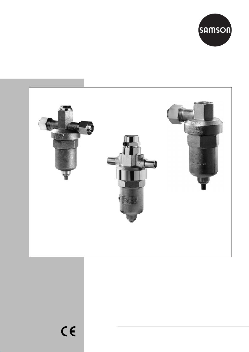
Pressure Reducing Valve Type 2357-1/-6
Excess Pressure Valve Type 2357-2/-7
Type 2357-1 Pressure
Reducing Valve
Type 2357-2 Excess
Pressure Valve
Type 2357-6 Pressure
Reducing Valve
Mounting and
Operating Instructions
EB 2557 EN
Edition April 2011
Page 2

Contents
Contents Page
1 Design and principle of operation . . . . . . . . . . . . . . . . . . . . . . 3
2 Installation . . . . . . . . . . . . . . . . . . . . . . . . . . . . . . . . . 5
2.1 Mounting position . . . . . . . . . . . . . . . . . . . . . . . . . . . . . . 5
2.2 Shut-off valve and pressure gauge . . . . . . . . . . . . . . . . . . . . . . 5
3 Operation. . . . . . . . . . . . . . . . . . . . . . . . . . . . . . . . . . 6
3.1 Set point adjustment . . . . . . . . . . . . . . . . . . . . . . . . . . . . . 6
3.2 Changing the set point range. . . . . . . . . . . . . . . . . . . . . . . . . 7
4 Dimensions in mm and weights . . . . . . . . . . . . . . . . . . . . . . . 9
General safety instructions
The regulators must be installed, started up and serviced by fully trained and
4
qualified personnel only, observing the accepted industry codes and
practices. Make sure employees or third persons are not exposed to any
danger.
All safety instructions and warnings in these instructions, particularly those
concerning installation, start-up and maintenance, must be observed.
For appropriate operation, make sure that the regulator is only used in
4
applications where the operating pressure and temperatures do not exceed
the operating values based on the sizing data submitted in the order.
Note that the manufacturer does not assume any responsibility for damage
4
caused by external forces or any other external factors.
Any hazards which could be caused in the regulator by the process medium
or operating pressure are to be prevented by means of appropriate
measures.
Proper shipping and appropriate storage are assumed.
4
The declaration of conformity issued for a valve bearing the CE marking
4
includes information on the applied conformity assessment procedure and
will be provided on request.
2 EB 2557 EN
Page 3

Design and principle of operation
1 Design and principle of
operation
The pressureregulators maintain the pressure
at an adjusted set point and are particularly
suitable for cryogenic applications.
Type 2357-1 and Type 2357-6 Regulators
(globe valves)
The regulators act as pressure reducing
valves when the medium flows from port A to
port B. When no pressure is applied, the
valve is open.
The pressure downstream of the valve B is
transmitted to the operating diaphragm (3).
The resulting positioning force moves the
valve plug (2) in relation to the spring force,
which can be adjusted at the set point adjuster (10). The valve closes as the pressure
downstream of the valve B increases.
When the regulators are used as pressure
build-up regulators, the medium flows from
port B to port A. The pressure upstream of the
valve (B) is transmitted to the operating diaphragm (3). The valve closes as the pressure
upstream of the valve increases and opens as
the upstream pressure drops.
The pressure build-up regulator additionally
assumes the function of a safety valve,
depressurizing the pressurized valve when
the set point is exceeded by more than 5 bar.
When the pressure has overcome the force of
the springs located on top, the valve opens to
balance the pressures.
Type 2357-2 and Type 2357-7 Regulators
(angle valves)
The regulators functioningas excesspressure
valves, the medium always flows from port A
to port B. When no pressure is applied, the
valve is closed. The pressure at port A acts on
the operating diaphragm (3) in the valve
body. The resulting force opposes the adjust
able spring force. As the pressure increases,
the valve opens until the set point is reached.
Regulators functioning as excess pressure
valves can optionally be equipped with a
non-return unit (12) which prevents the me
dium from flowing back.
EC type examination
An EC type examination according to the
Pressure Equipment Directive 97/23/EC,
Module B has been performed on the regulator versions for PN 50.
-
-
EB 2557 EN 3
Page 4
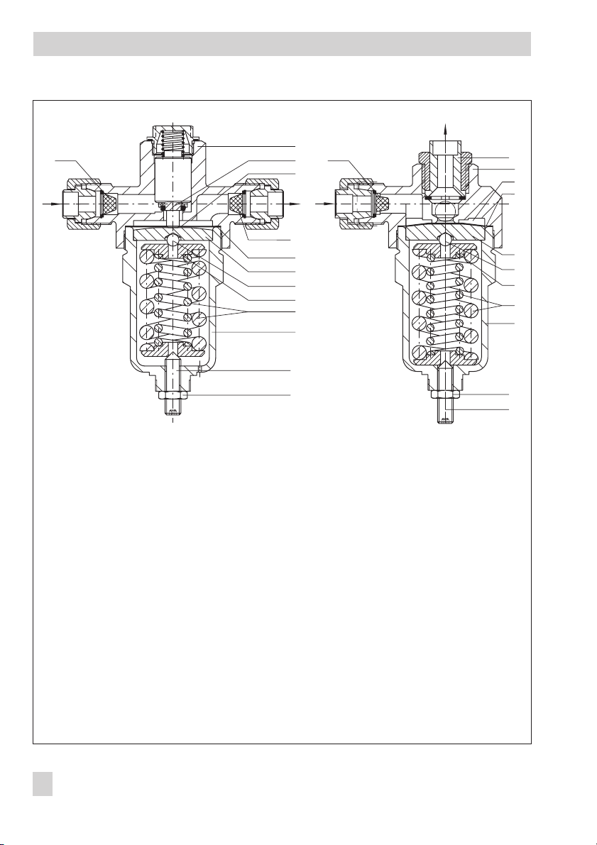
Design and principle of operation
7
B
1
2
13
13
3
AA
B
12
1
3
4
13
4
5
5
6
6
7
8
9
8
9
10
11
1 Body
2 Plug
3 Operating diaphragm
4 Gasket
5 Diaphragm plate
6 Ball
Fig. 1 · Sectional drawings of Type 2357-1/-6 (left) and Type 2357-2/-7 (right)
7 Spring plate
8 Set point spring(s)
9 Lower section of body
10 Set point adjuster
11 Lock nut
12 Non-return unit
13 Strainer
4 EB 2557 EN
11
10
Page 5

Installation
2 Installation
2.1 Mounting position
The pressure regulator must be in
stalled with the actuator housing
hanging downward.
Observe the following directions of flow:
A to B in pressure reducing valves
4
B to A in pressure build-up regulators
4
with safety function
A to B in excess pressure valves
4
equipped with a non-return unit. Port B
must point upward.
The ports are marked.
Note: Make sure that any impurities carried
along by the process medium in the connected pipelines do not impair the proper
functioning and especially the tight shut-off of
the regulator.
-
2.2 Shut-off valve and pressure
gauge
We recommend installing a hand-operated
shut-off valve bothupstream anddownstream
of the regulator to be able to shut down the
plant for cleaning and maintenance, and
when the plant is not used for longer periods
of time.
Install a pressure gauge both upstream and
downstream of the regulator to monitor the
pressures prevailing in the plant.
11232
1 Shut-off valve
2 Pressure gauge
3 Pressure regulator
Fig. 2 · Typical installation
EB 2557 EN 5
Page 6

Set point adjustment
3 Operation
3.1 Set point adjustment
The pressure regulator is adjusted at the
factory to the set points listed in the table.
However, you can change them by turning
the set point adjuster (10).
When pressure gauges are installed in the
connected pipelines, you can adjust the de
sired set point directly while monitoring the
corresponding pressure gauge.
When no pressure gauge is installed, use the
adjustment diagram to adjust the set point.
To increasethe set point, turn the setpoint ad
juster into the body, and to decrease the set
point, turn the set point adjuster out of the
body.
1. Undo the lock nut to allow the set point
adjuster to move freely.
2. Determine the difference between the
fixed set point (table below) and the required set point. Turn the set point adjuster the required amount of turns as
specified in the diagram.
Any subsequent change in set point can
be also be made by determining the re
quired number of turns using the specifi
cations listed in the table in “Set point
change per turn”.
-
3. Secure the setting with the lock nut.
Set point/Set point range in bar
40
35
-
30
25
-
20
15
10
5
0
0 1 2 3 4 5 6 7 8 9 10 11 12 13 14
-
Fig. 3 · Adjustment diagram
10 to 36
5 to 25
1 to 25
Turns of the set point adjuster
8 to 40
1 to 8
Table 1 · Set point adjustment
Nominal pressure PN 40 PN 50
Set point range in bar 0.2 to 3 1 to 25 10 to 36 0.2 to2.5 1 to 8 5 to 25 8 to 40
Set point
adjusted at the
factory to
approx. … bar
Set point change per turn
in bar
2357-1 1 12 20 1 3 12 25
2357-2 1 13 21 1 4 13 26
0.4 2.5 3.5 0.4 1 2.5 3.5
6 EB 2557 EN
Page 7

Operation
3.2 Changing the set point range
The set point ranges adjusted by themanufac
turer can be changed subsequently by ex
changing the set point springs (8) and the op
erating diaphragms (3).
In case of doubt, we recommend you to let
SAMSON perform this work for you.
The addresses ofSAMSON AG, its subsidiar
ies, representatives and service facilities
worldwide can be found on the Internet at
www.samson.de, in a SAMSON product cat
alog or on the back of these mounting and
operating instructions.
CAUTION!
Always remove the regulator from the pipe
when performing anyassembly work. Prior to
removing the regulator, relieve the pressure
as well as thaw and drain the corresponding
section of the plant.
1. Unscrew the lock nut (11). Completely re
-
-
-
-
-
lieve the set pointsprings (8)of tension by
turning the set point adjuster (10) in a
counterclockwise direction.
2. Place the lower section of the body (9)
into avise, but do notclamp it. Better: use
a box wrench with width across flats =
55 mm. Unscrew the body (1) using an
open-end wrench with width across flats
= 36 mm and remove all parts from the
lower section of the body. Be careful not
to damage the operating diaphragms
(3).
3. Install set point spring(s) for the required
set point range, the spring plates (7), the
ball (6) and the diaphragm plate (5) in
the lower section of the body.
4. Place the required number of diaphragms (see table of spare parts) onto
the diaphragm plate and replace the
PTFE gasket (4) of the valve body, if required.
5. Carefully place the body onto the lower
section of the body. Then screw the body
onto thelower section of the body using a
tightening torque of approx. 180 Nm for
PN 40 and approx. 250 Nm for PN 50.
-
EB 2557 EN 7
Page 8

Spare parts
Table 2 · Spare parts list with order numbers
Spare parts list Order no.
PN 40 PN 50
Set point range in bar
Pos. Spare part
3
Number of diaphragms 33357
Set of accessories:
with 20 diaphragms
with 50 diaphragms
4
Seals, set of accessories:
with 20 seals
with 50 seals
8 Set point springs
Non-return unit
12
for Type 2357-2
13 Strainer
Connecting parts:
Soldering nipple with
connection nut
1 to 25 10 to 36 1 to 8 5 to 25 8 to 40
1400-9747
1400-9747
1400-7626
1400-7627
1400-7630
1400-7631
1 to 25 bar
10 to 36 bar
1400-5129 (15 mm) or 1400-5139 (16 mm)
1400-5136 (270 x 10
1400-5126 (50 x 10
1400-5133 (1 xÆ15)
1400-5134 (2 xÆ15)
1400-5138 (1 xÆ16)
1400-5137 (2 xÆ16)
1400-9383 1 to 8 bar
1400-7640 5 to 25 bar
1400-7305 8 to 40 bar
1400-7623
1400-7624
1400-7628
1400-7629
-6
m mesh size) or
-6
m mesh size)
Note: Accessories and spare parts with order
numbers 1400-xxxxx are always delivered
"free from oil and grease for oxygenservice."
8 EB 2557 EN
Page 9

4 Dimensions in mm and weights
Dimensions in mm and weights
150
110
51(35)
140 (95)
Type 2357-1
Weight approx. 2.0 (0.9) kg
118
60
75
55
Ø16
G/
40
3
4
25
140 (95)
G/
3
4
Type 2357-2
Weight approx. 1.7 (0.8) kg
Values in parentheses for PN 40 version
Ø15
Ø16
Ø15
60
G/
3
4
40
Ø15
140
Type 2357-6
Weight approx. 3.0 kg
Fig. 4 · Dimensions
140
Type 2357-7
Weight approx. 2.5 kg
EB 2557 EN 9
Page 10

10 EB 2557 EN
Page 11

EB 2557 EN 11
Page 12

SAMSON AG · MESS- UND REGELTECHNIK
Weismüllerstraße 3 · 60314 Frankfurt · Germany
Phone: +49 69 4009-0 · Fax: +49 69 4009-1507
Internet: http://www.samson.de
EB 2557 EN
S/Z 2011-04
 Loading...