

Page 1

Page 2
SJJMS_C_Q_M_P_U_~_ER_~_A_C_T._S_T"
________
M_O_DZ_EEL_N~T_
V~_.1_35
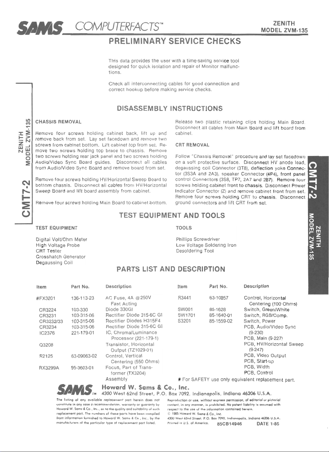
PRELIMINARY SERVICE CHECKS
This
data
prov i
des
designed
tions
Check
correct
for
quick isolation
_
all
interconnecting
hookup
before
DISASSEMBLY INSTRUCTIONS
the user
with
a time-sav ing service
and repair of Moni
tor
cables for good connection and
making
service
checks
_
too
malfunc-
l
~ CHASSIS REMOVAL
Remove four screws
:I:~
~>
re
move b
-N
sc
Z...J
Ww
move
NO
two
o
AudiolVideo Sync
~
fro m
Remove fo
botto
Swee p B
Remove
ack
rews fr
om
two
screws holding top brace
screws
AudiolVide
ur
m chassis. Di
oar
fou
holding rear
d and li
r s
TEST EQUIPMENT
Digital Volt/
Oh
High Voltage Probe
RT
Te ste r
C
shatch
Cros
De
gau
Generator
ssing
Item
holding
from set. Lay set
cabinet
bottom
. Li ft cabinet to p from se
jack
Board guides . D
o Sync Boa
screws
sconnec
ft
crews
rd
holding
t all cables from HV/
board
assembly
hol
ding
m Meter
Coil
Part
No
.
Release
Disconnec t all cabl
cabinet
facedown
back, l
ift
and remove
up and
t.
to
chassis. Remove
pane l and
two
screws
isconnect
holding
all cables
and remove board from set.
HV/Hor
izontal Sweep Board
Horizontal
from
cabinet
.
cabinet.
two
CRT REMOVAL
Re-
Follow
on a
soft
degaussing coil Conn
tor
(3S3A and 2A3), speaker Con n
control
to
screws holding cabinet fro
dicator
In
Remove four screws holding CRT
Main Board
to
cabinet
bottom
ground conn
.
TEST EQUIPMENT AND TOOLS
TOOLS
Phillips Screwdriver
Low Voltage Soldering Iron
Desol
PARTS LIST AND DESCRIPTION
Description
Item
two plastic
"Chassi
protec ti
Connecto
Connector
ecto
der
ing Too l
retai ning
es
from Main Board and
s Remova
ve
surface. Disconnect HV anode lead,
ector (3T
rs (3S8, TP7, 2A7 and 2
(Z)
and remove cabi net fr
rs and lift CRT from se
No_
Part
clips
holding Main Board.
lift
l"
proced ure and lay set facedown
8),
de flection yoke Connec -
ect
or
(4P4),
B7)
. Remove four
nt
to
chassis
. Disc
onn
to
chassis. Disconnect
t.
Description
board from
front
ect Powe r
ont
from set.
panel
#FX320 1
CR3224
CR3231
CR
3232/33
CR3234
IC2376
Q3208
R2125
RX
3299A
36
1
103-330
103-315-06
103-31
103-315-06
2
21
63
95-3603
r
t,.
l
ist
ing of any availa
conSlitut.
in any
Howa
rd
W. Sams & Co .. Inc .. as
replacement
om
informati
fr
manu
facture
-113-23
5-06
-17
9-0
1
-09063-02
-0
1
case
0
part.
The
numb.rs
on furn
ished
rs
of 'he
particular
AC
Fuse, 4A @250V
Fast
Act
ing
Diode 330GI
Rectifier
Rectifier
Rectifier
IC,
Trans
Cont
Focus, Part
Diode 315-6C GI SW1701 85-1640-01
Diodes H315F4 53201
Diode 315-6C
GI
ChromaiLuminance
Processor
tp
Ou
(221-179-1)
istor, Hor
izontal PCB, HV/Horizontal Sweep
ut (TZ1029-01) (9-247)
rol, Vertical PCB, Vid
Centering
(550 Ohms) PCB, Start-up
of
Trans- PCB, Width
R3441
SW001 85-1628
63-108
57
85-1559-02
former (TX3204) PCB, Control
Assemb
Howard
4300
ble
r.placement
recommendation,
to
of
to
Howard
type
ly # For SAFETY use onl y equivalent repl
W.
the
these
West
of
quality
W.
replacement
Sams
62nd
Street,
port
herein
warranty
or
and
suitability
ports
have
been
Sams & Co., Inc.,
part listed
does
guaranty
of
compiled
by
not
by contenf
such r
the
.
& Co., Inc.
P_O. Box 7092,
Reproduction
.
in
any
espect
to
the
~ 1985
Howard
.. 300
West
62nd
Printed
in
U.S.
Indianapolis,
or
U
S.,
wifho
monn.
r, Is
of
the information
W.
sams
Str
..
t,
Americo.
prohibited.
&
P.O
use
of
ut
expre"
Co
"
Inc
.
.
So.
7092 , I
85CB14946
Indiana
perminion,
No
contained
ndianapolis
patent
Cont
rol, Horizontal
Cen
ter
ing (100 Ohm
Swi tch, Green/Whi te
Switch,
Sw
PC
RG
B/Co mp.
it
ch, Power
B, AudiolVideo Sync
(9-230)
ai
n (9-22
eo
7)
Output
PCB, M
acement part.
46206 U.S.A.
of
editori
al or
dian
it
aSiumed
a
~206
pictoriol
wit
U.S.A.
h
liability
herei
, In
n.
DATE 1·85
s)
Page 3

PRELIMINARY SERVICE CHECKS (Continued)
PRELIMINARY SERVICE CHECKS (Continued)
MISCELLANEOUS ADJUSTMENTS
SEE
INTERCONNEC
THE
NUMBER
CHECKS
DEAD MONITOR
(A)
(B)
(C)
(D)
(E)
(F) If the 26.9
(G) If
NO DISPLAY
(A)
(B)
(C) If
TO BE PERFORMED.
Che
ck for
nector
ord
C
If Po
(S3201) and Connec
If
chec
Power
If Power
good,
(03208).
it and
sistor
If
Transistor 03208
colle
for
(9·227).
the
not operate, replace the HV/Horizontal Sweep
Board
Check
be
If there is
video, replace
(IC23
the
Au
120VAC b
3R8. If v
and Conn
wer
Cord is good, check Power Sw
the
120VAC is present at
k AC
Fuse (FX32
Rectifiers
Rectifier
check the Hor
If
Transistor
check
0320
8.
ctor
of
26.9V at
defective
diolVideo
Transistor
the
V is
26.9V is present and
(9
·24
7).
the
RGB/C
no
76)
on th e AudiolVideo Sync Board.
video
displa
TING DIAGRAM,
IN
THE
CIRC
LES
etwe
en
olt
age is missing, check Power
ector 3R8.
tor
(CR3231 th
s (CR3231 thru CR3234) are
for
156V at the
cathode of Diode CR32
missing,
omp Switch (SW1701), it may
or
in wrong
display
the
Chroma/Luminance Processor
y does
Syn c Board (9·
pins 1 and 3 of Con-
3S8.
01)
izontal
03208 is defective, replace
is good, but the
03208
when using only c
Connector
. If Fuse is open,
ru CR3234)
Output
collector
is
missin
replace the Main Board
the Monitor
position
.
not
return, replace
230).
SERVICE CHECKS
WITH
Transistor
of
156V
g,
24.
check
Tran·
at the
check
PLACEMENT
THOSE
itch
3R8,
CD
CHART, AN
IN TH E FOLLOWIN G DATA FOR SERVICE
(D)
(E)
NO COLOR
(A)
(B)
(C) If there
(D)
@ NO FOCUS
still
does
(A) Check
(B)
@ DISPLAY DOES NOT FIT ON CRT
omposite
(A) Check
the
(B) Adjust
D PHOTOS TO
If
there is no
Compos
the
HV/H orizont
missing, repla ce the
(9
·247).
Check
Board.
If there is no
video input, replace
cessor (IC237
If
the
A
udiolVideo
the
Green/White
If only one
put
Boa rd by
tion.
If
the
fo
cus, check
substitution.
Board.
Centering
disp
lay when
ite
Video inputs
al
Sweep Board.
CRT and CRT
color
6)
on
color
does n
Sync Boar d (9·2
is
no
color
Switc
color
is
substitution.
the
Focus
Control
cha
racters on the
the
connectors
Horizontal (R34
controls
MATCH
using either
, ch
eck for 95V at TP3 on
HV/Horizontal
socket
on Video
when
using
onl y
the
Chro
the AudiolVideo
when
missi
.
ma/Luminance Pro-
ot
return, replace
30)
.
using RGB
h (SW001).
ng, check
(RX3299A) by s
displa
Video Output Bo ard by
P1A and
y are
P2
41)
and Vertical (R212
RGB
If
the
voltage
Sweep Board
Output
composite
Sync board.
input,
the
Video Out·
ubs
still
on the W
or
is
the
cheCk
titu
out
ith
of
5)
VIDEO INPUT CUTOF F ADJUSTMENT
Preset the Red (R1708) and
MINIM
UM. Ad
pears. Ad
tained. Readjust
pears.
APC ADJUSTMENT
Connect a color
Ohm Ja
·Up position
Set
movem ent of color. Return Plug A 1
RGB
CUTOFF ADJUSTMENT
Preset the Red (R2505
Cutoff Controls
(RX3499B)
Control
RX3499B
RGB
DRIVE ADJUSTMENT
Conn ect a video generat or to Video
vi
deo generator
Set
Red (R2506), Green (R251
for a white
VERTICAL CENTERING AND HEIGHT ADJUSTMENT
Adjus
t Screen
just
Vertical
ing Con
of CRT
CRT. Readju
SWEEP OSCILLATOR ADJUSTMENT
Ad
just
·
just
just
each
the
ck
until
trol (R21
an
Sweep
bar signal gener
(P7)
. R
otate
. Ad
for
until a dim raster
a gray raster is
until
raster disappear
raster.
Control (RX3499B)
Height Control
25)
d the bottom
st
Control (RX3499B)
Oscill
Blue (R17
Screen (R3499
Cut
off
Control
Screen
Service Plug (A
just APC Contr
),
Green
MIN IMU
for
an all
7)
and Blue (R25
(R3418) and the Ver
so the
top
of
raster is 1/2
ator
Coil (L3402) for a
14)
Cutoff
Controls
B)
until a dim
until
Control
M.
appears. Adjust each
obta
s.
white
of raster is 1/2
a gray raster is ob·
until
raster
just
ato
r to th e Video
1)
90 degrees
ol (R2390)
to
(R2
516
Ad
ined. Readjust Control
Input
raster signal. Adjust
until
until
for
MINIMUM
Normal
position
),
and Blue (R2527)
jus
t Screen Control
75 Ohm Jac k (
28)
Drive
a ras
ter
appears. Ad·
tical
inch
inch
from
raster disappears.
stable
raster ap·
disap
Input
to
Co lor
.
Cuto
P7)
the
Controls
Center·
from top
bottom
picture
95V ADJUSTMENT
for
Connect a DC
Transformer
95V.
·
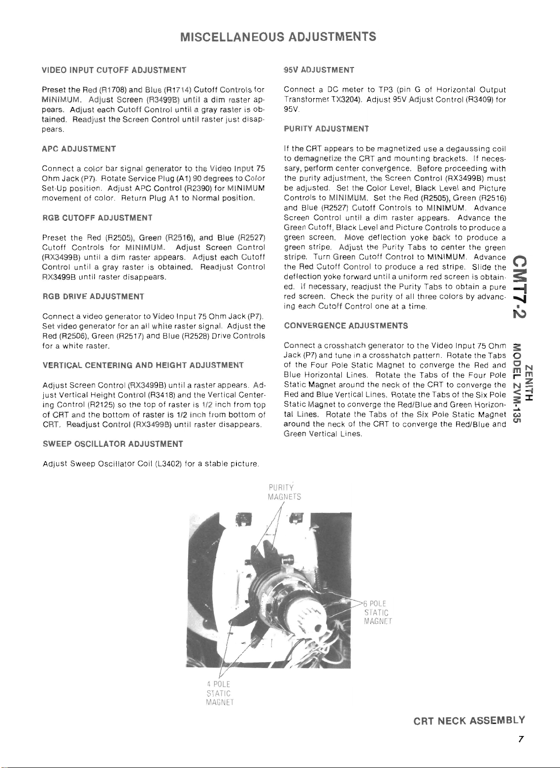
PURITY ADJUSTMENT
If the CRT appears
to
75
ff
.
of
.
demagnetize the CRT and
sary,
perfo
the
purit
be
adjusted.
Cont
rols
and Blue (R2527) C
Screen Co
Green
Cutoff
scr
green
tr
green s
stripe. Turn Gree n Cuto
the
Red Cutoff
defle
ctio
ed. If necessary, r
red screen. Check the
ing each
CONVERGENCE ADJUSTMENTS
Connect a cross
Jack
(P7
of
the
Four Pole
Horizontal
Blue
Static
Magnet aroun d the neck
Red and
S
tatic Magnet
tal Lines. Rotate the Tabs
around the neck of the CRT to converge the Red/Blue and
Green Vertic
PU
RiTY
MAG:-.iHS
meter
to TP3 (pin G
TX320
4). Adjus
to
rm
center
y adjustment
Set th e Color Level , Bl
to
MINIMUM. Set
utoff
ntrol
until a dim
, Black Lev
een. Move
ipe. Ad
n yoke
Cutoff
) and tu ne in a
Blue
just
Control to
for
ward
eadjust
Control
hatch
Static Magnet
Lines. Rota te
Vertical Lines. Rotate the Tabs of the Six Pole
to
converg e the Red/Blue and Green Horizon·
al
Lines.
t 95V
be magnet ized use a deg aussing
mounting
convergence. Before proceeding
, the Screen
the
Controls
raster appears. Adv an ce the
el
and P
def
lection yoke
the Purity Tabs
ff Contr
produce
until a uniform
the
purity
one at a time.
generato r
crosshatch
of
of
Horizontal Ou
Adjust Control
bracke ts. If neces·
Control
ack
Lev
Red (R2505), Green
to
MINIMUM. Advance
ictu
re Con
tro
back to pr
to
ol to MINIMUM. Advance
a red stripe. Slide
red screen is obtain·
Purity
Tabs to
of all three
to
to
the
of
the Six Pole St
colors
the Video
patte
rn. Rotate
converge the Red and
Tabs
of
the CRT to con verge the
(R3
(RX3499B)
el
and
ls to pro
center
the green
obtain
by advanc·
Input
the Four
atic
tput
409)
with
must
Picture
(R251
duce
oduce
a pure
75
Ohm
the
Tabs
Pole
Magnet
for
coil
6)
the
a
a
@
®
R3499B
@A
SCREEN
95V
TP
POLE
Sf
ATle
MAGNc
T
4
POi
f:
SiATiC
MACN[
r
CRT NECK ASSEMBLY
HV/HORIZONTAL
SWEEP BOARD
II
Page 4

PRELIMINARY SERVICE CHECKS (Continued)
PRELIMINARY SERVICE CHECKS (Continued)
/
AOOIO{OOT
IN(
~
,\::::>,ffi-+--4
/'"-
-1-
AUDIO/VIDEO
®®
SYNC
@)
SOARD
CHla'toVLl.tlI
®
297
If..
III
LL~
NANCE
PROCESSOR
~
IC2~S
I
,.1
L...LL
I
I
Y
l.IL
/'lAIN
BOARD
2A3
C:;]'
1
HV/HOR
SWEEP
SOARD
I
ZONTA
L
@@
fi-
-
-
2A7
-
-
--..
Q
-
1-
~
0B25
RGS
IN
R344
~
~
[;J C
I
HOAIZCWTAl
CfHTERIN6
01
1 E
@)
58
~
I X
R2125 @
VERTI
CAL
CENTERIN6
-fi
_
~
t:<::\
~
CR3224
3W3
• I
I.
~
IS4V
SOURCE
3V3
.
T3201
'-'
I!f-J
~
:
3S3
.----_+---
fll
J......l
,
TP3
@
FOCUS
~
3R3
~
L---
PIA
---+-----t-t-t--J
WIDTH
BOARD
f"5A\
\::!.Y
SPI
SPEAKER
INTERCONNECTING DIAGRAM
VI
!il'
I!.J
TPS
SHARPNESS
00000
TINT
COlOR9LACK
LEVEL
PICTURE
'~
!I'
=;;"
~
I I
lrh,
~
@=p~
sw
ITCH
~'r
26.9V
@@
SWITCH
AND
VOLUME
MOUNTIN6
0
VOlt.t£
CONTROl
BRACKET
I
-&
~
~
@
t;1
=TES
TIE POINT
353
~U
P2
~
~
INTERCONNECTING
DIAGRAM
III
Page 5
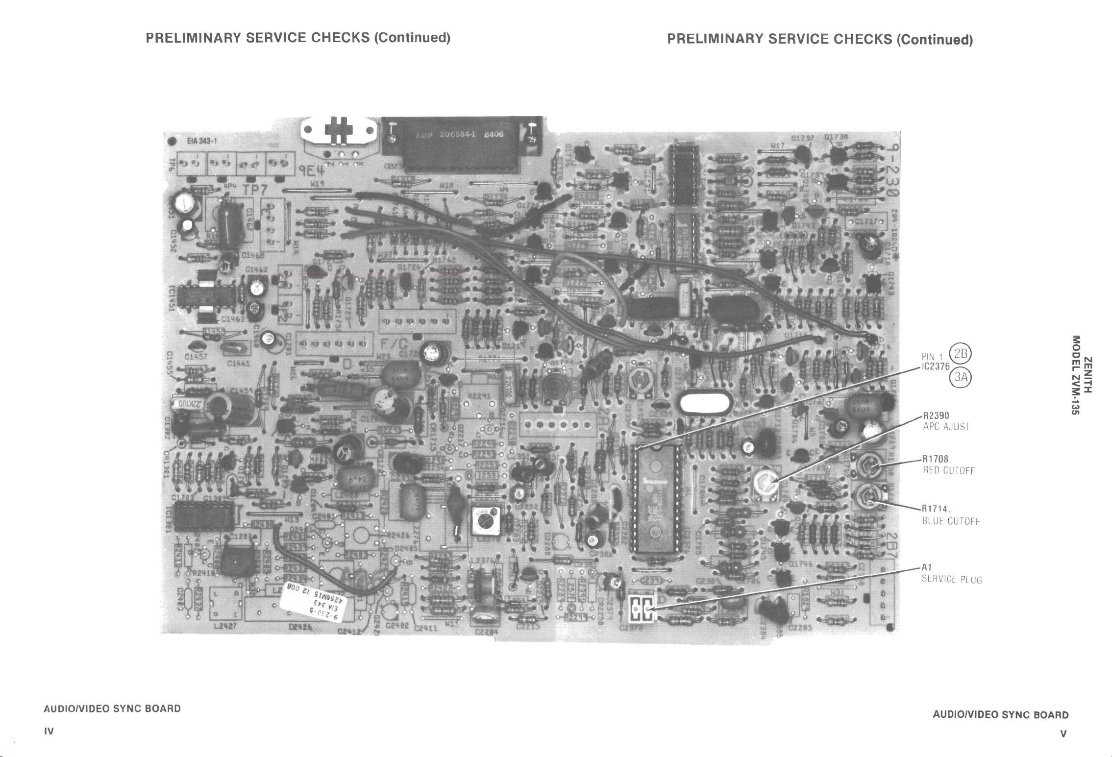
PRELIMINARY SERVICE CHECKS (Continued)
PRELIMINARY SERVICE CHECKS (Continued)
PIN1
@
IC2376~
0.Y
R2390
APC
AJUS
1
RH08
RtD
CUTOFF
R1714.
I:lLUt
CUTOFF
Al
StHVICE:
PL
UG
3:
o
eN
mm
""'z
N-
<-4
3:~
.....
(,.)
C1'I
AUDIOIVIDEO SYNC BOARD
IV
AUDIOIVIDEO SYNC BOARD
V
Page 6
<
<
3:
»
z
tD
o
»
:::D
c
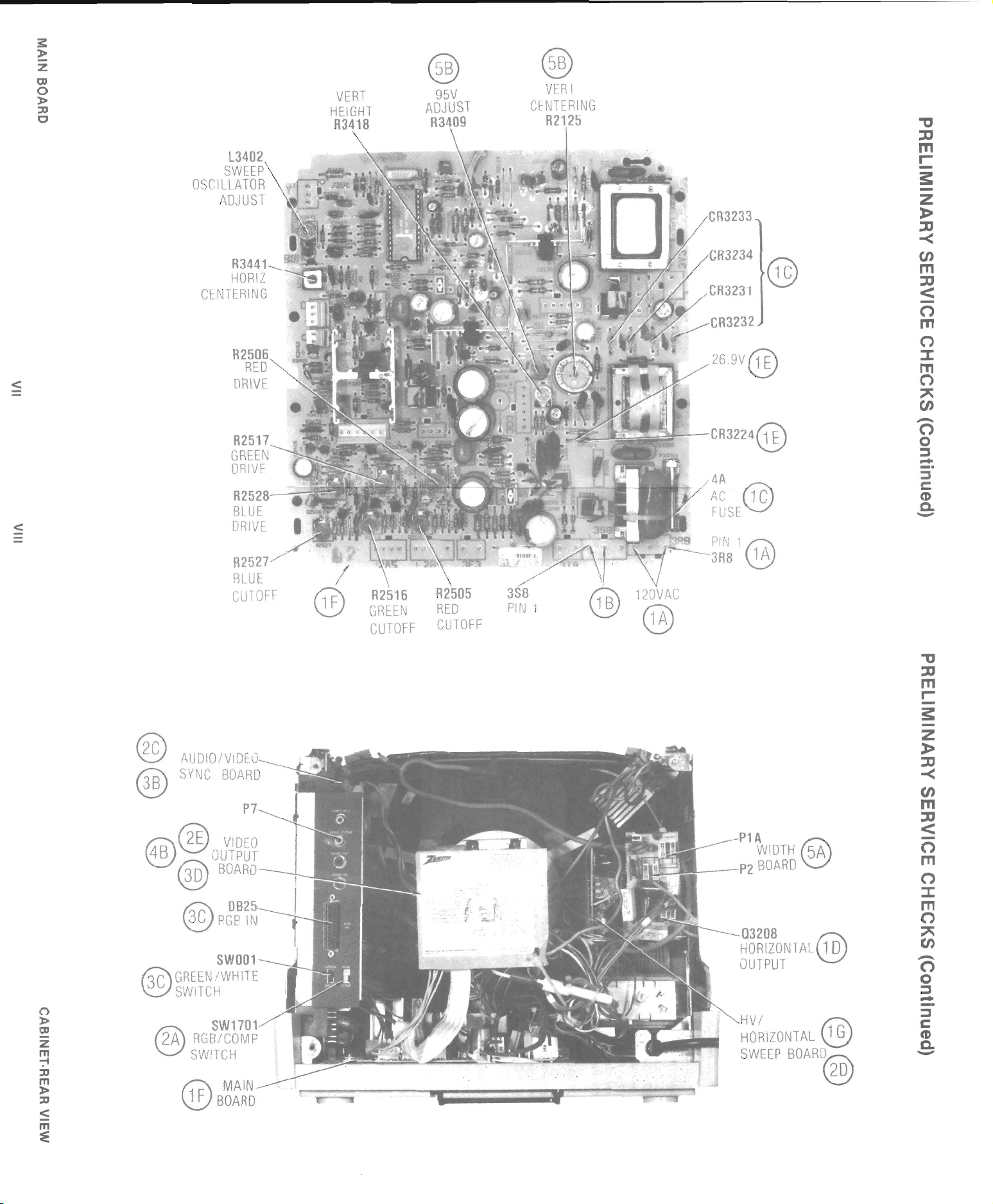
L3402
SWEEP
OSCILLATOR
ADJUST
R3441
HORll
CENTERING
A250
REO
DRI
VE
A2517
GREEN
ORIVE~~
R2528-
BLUE
DRIVE
®
VERI
CI::NTERING
A2125
R3233
CR3234
VERT
HEIGHT
A3418
®
95V
ADJUST
A3409
@
CR3231
CR3232
26.9V
@
~
-
,..,
..
A.
2f
r
.xr:~.tiJ-A'L..&.~"e:-,
..
CA3224@
4A
AC
@C
FUSE
"'tJ
JJ
m
I'
-
s:
z
»
JJ
-<
CJ)
m
JJ
<
-
C')
m
C')
:%:
m
C')
CJ)
"
C')
-
o
::s
-
::::J
C
(I)
Q.
-
o
l>
tD
Z
m
":-'
:::D
m
»
:::D
<
m
::E
®
®
~@
~
@
~
®P
f3C\
GREENIWHITE
~
SWITCH
f2i0
V
SWITCH
1 F
®
R2527
BLUE
CUTOFF
P7
VIDEO
OUTPUT
BOARD
082
GB
IN
SW001
SW170
RGB/COMP
MAIN
BOARD
/
@
R2516
GREEN
CUTOFF
. f
1-,'
I
.':
rl
.'
( -.
120VAC
@
~~~1
@
P1A
WIDTH@
-P2
BOARD
Q3208
HORIZONTAL
OUTPUT
VI
HORIZONTAL
SWEEP
BOAR~
~
@
10
f1'"2\
&
@;
"'tJ
JJ
m
I'
s:
Z
»
JJ
-<
CJ)
m
JJ
<
-
C')
m
C')
:%:
m
C')
CJ)
"
C')
-
o
::::J
-
::s
c
(I)
Q.
-
Page 7
a_
~
...
W~.
5
It)
C'?
":'"
:x::ii!
....
>
-N
Z....l
Ww
NO
0
:ii!
N
•
t--
I-
:E
(J
~
COM UT R ZENITH
_______
P
__
IE
__
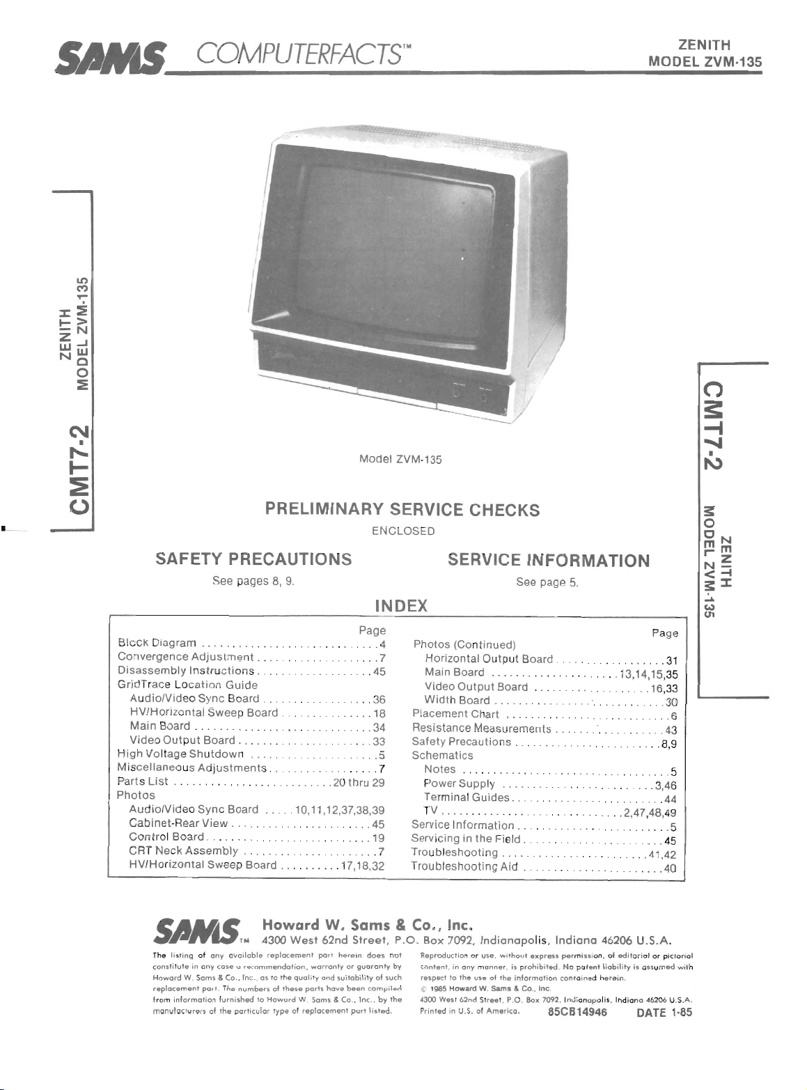
PRELIMINARY SERVICE CHECKS
SAFETY PRECAUTIONS
See pages
8,
9.
FA_C
__
Ts_rM
Mode
l ZVM·135
ENCLOSED
______________
SERVICE INFORMATION
See page
~MO_D~EL_Z~VM_'1~35
3:
o
ON
mm
r""Z
N-
5.
<-4
3:::I:
B
lock
Diagram
Convergence
Disassembly Instructio
Gri dTrace Lo
AudiolVideo
HV/H ori
Main
Video Outp
High
Volt age Sh
cellaneo
Mis
Parts
Photos
AudiolVi
C
abinet
Co
ntrol Board.
CRT Neck
HV/
Adjustment.
cation
Guide
Sync
Board
zonta
Board . . .
List
Horizontal Swee p Board
The
constitute
Howard
replacement
from
manufact
l Sweep
........
ut
Board . . . . . . . . . . . 33
utdown . . . . . . . . .
us
Adjustments.
. . . . . . . . . . . .
deo
Sync Board . .
·Rear View . . . . . . . . . . . . .
Assembly
listing
of
any available replacem
in any
cose a recommendation,
W. Sams &
Co., Inc.
port. The
information
urers
furnished
of
the
..
......
. Photos (Continued)
ns . .
Board.
.
. .
...
10,1
. . ....
...•.
Howard
West
4300
ent
, as
to
the
to
of
Howard
type
quality
these
parts hO\lle
W. Sams & Co .. Inc. .
of replacement
numbers
partlCulor
.
.........
20
thru
1,12,37,38,39
.
....
..... 17,18,
W.
Sams
62nd
port
herein
warranty
or
cnd
suitability
been
port
INDEX
Page
....
4
'"
. 7
45
. .
.36
...
18
. 34
..
5
. 7
29
.45
. 19
7
32
Street.
does not
gua
ran
of
compiled
by
listed.
Horizontal Output Board
Main Board
Video
Widt
Placement Chart
Resistance Measurements .
Safety Precautions
Schematics
Notes .......
Power Supp ly ......
Termi nal Guides . .
TV
..
Service I
Servicing in the Field.
Troubl
eshooting.
Troubleshooting
..
Output
h Board
nformation
& CO., Inc.
P.O
. Box 7092.
Reproduction or
ty
by
content, in
such raSpEKf
~
1985
the
"300
Pr
inled in
cny monner
to
the
How
ard
West 62nd
U.S. of
Indianapo
use, without
us.
of
W.
Saml
Street
America.
. ....
.. ..
Board
.........
.....
...
Aid
lis .
express
, is
prohibited.
th.
information
&
Co.
, Inc.
. P.O . Box 7092. I
Pa
ge
........
.
. . .
........
. . . . . . .
. .
. 13,14,15,
. .
... 31
35
.. 16,33
...
30
..
. . 43
.8,9
. . . 5
.3,46
6
. ... 44
.2
,47,48,
49
.
....
5
. . . .
45
.41,42
.....
.. ..
40
Indiana
permissi
No
potent
containe
ndianapo
46206 U.S.A.
on,
of
editori
al
liability
lis .
erei
n.
India
is assu
na 46206 U.S
d h
or p
ictorial
med with
.A.
85CB14946 DATE 1·85
Page 8
ALC10
IN>UT
Clof67
.15
looV
FOO
SE
E
TERMINAL
PAGE
5,44
GUIDES
R1213
<100
AND
NOTES
L
-J~>-~
TP?
Rl'oo
va.1IE
151(
1
IC1151
:121-98.<05
ALOIO
11.1V
12.OY
PHOTO
CIACUITRACE
SCHEMA
TIC CI
RCUITRACE
11
--t-"""'"""Iii:IIH~
r
=
1
1.
S.-iY
!IV
R22?8
1800
R2255
•
......
-
oi
R710S
SHARf'Hf55
5000
11.1IV®
BlACK LEVEl
em
3300
R?
102
5000
4----,
<"
Rl 768
751(
RI767
300K
Q1729
Rl770
1000
499YIDE
Rl?69
1
O
m:
QI?30
A1'P
11
.1V
'99-1
VIDEO
A""
--,~>-
-~-
r
YEL
R2256'
1
000
~
R71
01
PI
CT(H
5000 11,8YaD
Rl79
51.
1K
R183?
2200
1 e
1,1"
e
Rl?89
2?.fK
Il
5
Ql
734YI[£O
."
'99-1
12.OVcm
APP
RI793
RI792
<100
Rl794
330
S60
8SS
Ql?
......
RED
Af'F
Rl?07
3000
t-
-,--
--
--<;
ITTl.2
11.9YW
11.IYW
8SS
Q1
?"'6 fl.t.E /lJ'P
l?13
R
3000
~JTf
VJDEO
JM'\IT
ll825
=kl
IH
C
l?03
IS1lpF
ll825
>--
NC
17
ll825
>--NC
23
ll825
>--NC
2'
Rl?61
-
VERT
COIf>
.,.
VERT
C(JF
m
SYNC
m
SYNC
R17S3
-
...
Rl
220
5DOO
RI755
?02
1000
3900
12.OV
JTT
SYNC
03of04»F
89S
01
R2287
151:
R2383
100
,
IW
RI830
151:
" ,
JYW
11
702
=1
.001
C2393
. 1
lOOV
i
1.S'VW
C3'28
.
01
10>
R3.f39
2000
IW
•
RX3209
100(>
• 11T9?5
Q1C3:/02
"tD
CF132(19
CR321
1
J7T142
2
SWITCH
R3222
1
00
R3"5
I
IlK
R3.of.ot5
2200
Q22
...
BUIS
15
GAT
..-----+
12.OV
T
E
IV
R2285
IB)
R23?8
R23S'
1
0K
8200
5 I N
SInSOl
ON
SHARPNESS
NOJSE
PROCESSOR
!TIl
ORMA
L!
i
;;....:;;
II
~
1
<>--0
- - J
F
ORAPC
AOJUSTI'£N
ROTATE
T
A1
.90.
r
r~T
R211lA
I
11, 9VaD
R2102
220
2fJ1
NC
R2129
220
11.IYW
" .WCA)
8SS
Ql?"'5~
AW
R1710
3000
PI
A PHOTOfACT STANOAI:O
W I
TH
14n3l1l'1'.1
© Howard
W.
Sam
2
NOTATION
, & Co
RI167
3900
..
Inc.
SCHEMATIC
1985
Rl?66
100
(1J
WA
8GB
GENERATOR
VEFORM
T
AKEN
AT
US J
8GB
NG
INPUT
•
T2.1YtID
RJ(32O$
SliOO
.
•
RX3210
HOO
R32e2
10K
CR3210
J7T112
10
>
~
CRT
X~I~
~~
+---
F
ILAIENTS
~
13
9
3
I
9
I
5 I 3
I
12
I I
Y
~1"'1+~
__
~,I
-=>
2
I
6 7 •
I I I
ZENITH
MODEL ZVM·135
Page 9
Jo,
CXJ
r-
o
(')
"
c
:;
C)
:lJ
:J>
s:
C
()ot)
VIDEO
JIf'IIT
,,1.(1)
IIf'IIT
OSJTf
SYNC
JIf'llTS
10
--{
~--1
r
AW
v/O£o
/O I
AI'P
_._
~~~
~
CHK»IA/ l
--
L
t..tIl NAHCf
lEE
I~T
(5T AItlAROJ
fLUE
,,*,,,
(APPlf>
GREfH
,,*,,,
(
STAM)AAQ
ilI££N
I
If'IIT
CAPf'lf J
r
r
>
--{fLUf
NIl'
(5T~_P«)ARD
)
~
_
{
----
GRf
~~-
}
EN _ _
~
--
Page 10
SERVICE INFORMATION
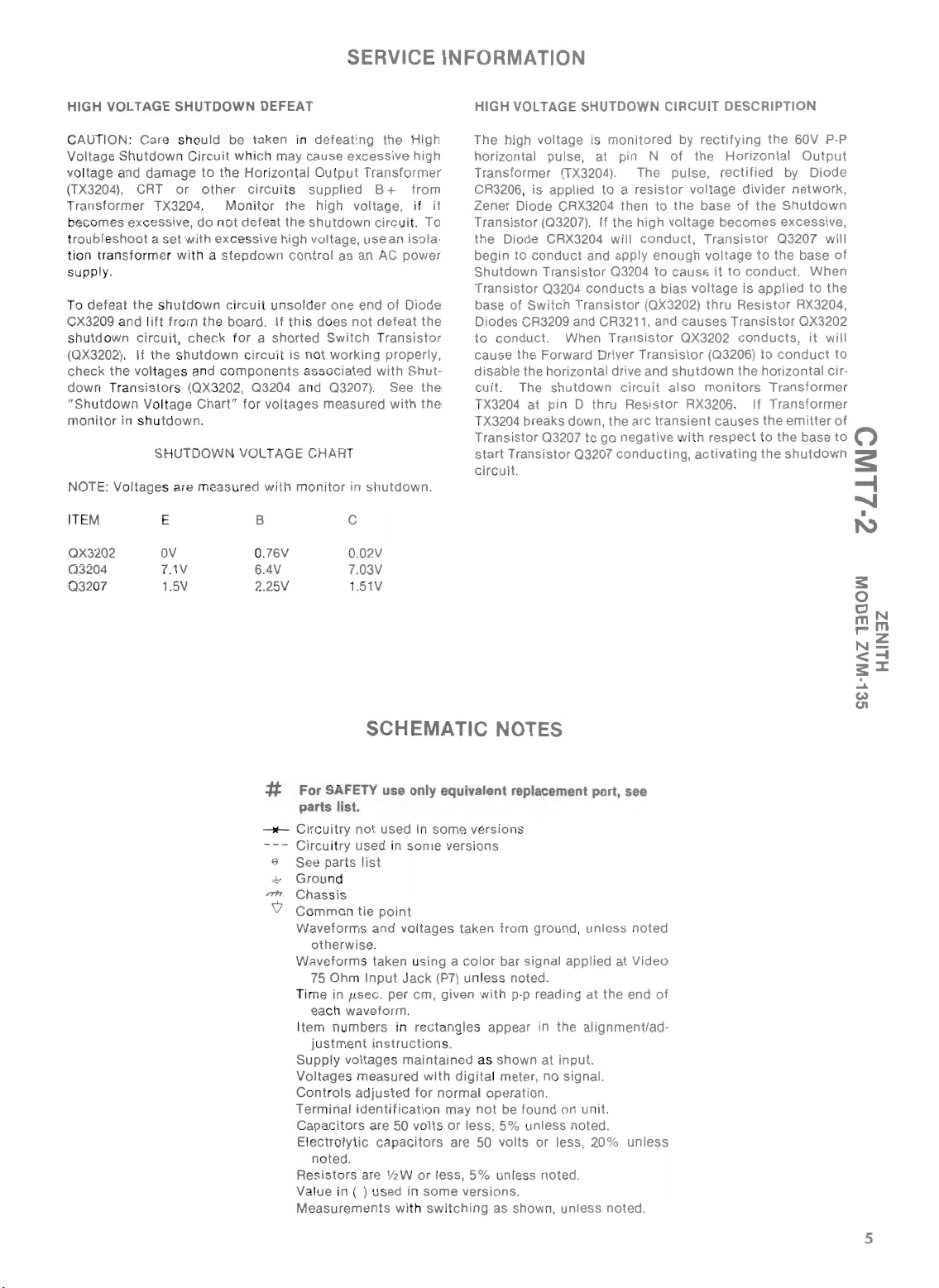
HIGH VOLTAGE SHUTDOWN DEFEAT
CAUTION: Care
Voltage
voltage and
(T
T
be
troubl esh
tion
supply.
To
CX3209 and l
shutdown circuit, ch
(OX3202). If
check
dow
"Shutdo
moni tor in shu
NOT
ITEM
OX3202
03204
0 3207
Shu
X3204
), CRT
ransformer
comes excess
oot
trans
defeat
the volt
n Transistors (OX3202,
wn V
E:
Vol tages are measured with monitor in s
sho
tdown Circuit
damage
a set with excessi
form
the shutdow
ift
the shutdo
uld
to
or
other
TX3204.
ive,
do not
er with a
from
the
eck for a shorted Switch Transistor
ages and
olt
age
Chart
tdown.
SHUTDOWN VOLT
E
OV
7.1V
1.5V
be taken in
whi ch may cause
the Ho rizontal
circu
its
Monitor
stepdown
n circu
board.
wn
comp
" fo r
the
defeat
the
ve
high voltage, use an isola-
control
it
unsold
If
this does
circuit
is not
onents
03204
voltages
AGE CHART
B C
0.
76V
6.4V
2.25V
and 03207) . See
defeating
Output Transformer
supp
high vo ltage,
shutdown
er one end
worki
asso
measured
excessive
lied B +
circ
as an AC
not
ng properly,
ciated
hutdown.
0.02V
7.03V
1.51V
the
uit. To
power
of
Diode
defeat
with
with the
Shut-
SCHEMATIC NOTES
High
high
from
if
the
the
HIGH VOLTAGE SHUTDOWN CIRCUIT DESCRIPTION
The high voltage is
horizontal pulse , at pin N
Transformer (TX3204). The pu Ise, r
CR3206, is appl ied
Zener Diode CRX3204 then
it
Transistor
the
begin to
Shutdown
Transistor
base of
Diodes CR3209 and CR3211, and
to
cause the Forward Driver
disable
cuit
TX3204 at pin D thru
TX3204 breaks down, the arc
Transi
start Transistor
circui
(03207). If the
Diode CRX3204 will
conduct
Transisto r
03204
Switch
conduct. When
the horizontal drive and
. The
stor
t.
shutdown
03207
monitored
to a resistor
and apply
03204
conducts
Transistor
Transistor
circ
Resistor
to
go
negative w
03207
conducting,
by
of
to
the
high
vol
tage
conduct,
enough
to
cause: it
a bias
(OX3202)
causes
OX3202
Transistor
shutdown
uit
also
RX3206.
transient
ith
rectifying
the
voltage
base
becomes
Transistor
voltage
voltage
thru
(03206)
monitors
causes
respect to
activating
the
60V
pop
Horizontal Output
ectified
to
Transistor
by
divider
of
the
Shu
excessive,
03207
to
the
conduct.
is
applied
Resistor
conducts,
to
conduct
the
horizontal cir-
Transformer
If
Transformer
the
the
the
shutdown
Diode
network
tdown
base
When
to
RX3204,
OX3202
it
emitter
base
will
the
will
,
of
to
of
to
0
:s:
--I
~
•
I\.)
3:
o
ON
mm
r-
Z
N-
<-4
3:::I:
.....
w
U'I
# For SAFETY use only equivalent replacement port, see
parts list.
__
Circuitry
Circu
9 See parts l
~
Gr
nh
. Chas sis
V C
ommon
Waveforms
Waveforms
Tim
tem numbers
I
Supp ly voltages
Vo
Cont
Term inal i
Capacitors
El
Resis
Value in ( ) used in
Measu
not
used in
it
ry
used in
ist
ound
tie
point
and voltages taken from
otherwise
75 Ohm Input J
e in fLsec. per cm, given w
each waveform.
stment
ju
lt
ages measured
ectr
noted
.
taken using a col
instruction
rols
adjusted
dentificat
are
olyt
ic
capaci
.
tors
are V2W
rements
some
some
versions
ack
(P7) unless noted.
in
rectangles
s.
maintai
ned as shown at input.
with digita
for
norma
ion may
50
vol
ts
or
tors
are
or
less,
some
with sw i
tching
versions
ground
, unless
or
bar signa l app lied at Video
ith
pop
reading at the end
appear in the alignment/ad-
l meter,
l operation.
not
less,
50
5%
versions
as show n, unless noted.
no
signal.
be found on uni
5%
unl ess noted.
volts
or less, 20%
unless noted .
.
t.
unless
noted
of
5
Page 11
LY
MB
ASSE
PANEL
INPUT
11l55
I j
A·
Z
HI
VIDEO
®
OHM
)5
VIDEO
®
BOARD
WIDTH
I
·IOS30
A
VIEW
TOP
OUT
®
AUDIO
PIA
o
IN
AUDIO
-,
---r
/ ,
D
®
:
.J
IOFF
o '
____
L
: ON
"
0'
\-
f
VOLUME
P2
"b
D
AR
BO
12
OUTPUT
CR32
IZ
OR
H
3SJ
o
SS
@)
SHARPNE
TINT
@)
LEVEL
LOR
~
LEVEl
BOARD
BLACK
CONTROL
0S
2·
S2
A9
PICTURE
@)@)@)
'"''
RGB
~Cj
GREEN
0'
1+
208
Q3
11
CR32
COMP
HITE
W
-.+
'
"
~
"
I I
fq
06
CR11
RANGE
BRIGHT
104
CR2
3405
ARD
CR
IN BO
MA
SA
9·m ·
WN
UTDO
32D)
SH
4
O
3
2A
13205
5
CR110
OUT
101
Q2
VERT
5M
+I
3401
L
20
CRX3
I-l
0
Q
0
.
o
~
i\~~~
0RIVER
Q
o
f
02
2
X3
O
L:J
SHUTDOWN
OJ]
3
•
3V
D
1
323
CR
3W3D
CR3133
) '
10
3G3
2
+t
CR
~
r.:-:-:-:l'
i:JJ
AMP
3402
00
Q
0
SYNC
31
Q
~
3408
CR
•
l...!J
r.l
[J
C
D.
1
I326
WIDTH
L
BOARD
m
EEP
SW
Z
_ . /
HORI
V/
H
---
I I
,
9-247A
LJ
r:::l
§l
D l
210:'
~
[*
t
CR3406
*
99
R21
C
2M
34DI
01
CR
34
VERT/HORIZ
PROCESSOR
IC
CR~04
CENTER
o
~
HORIZ
3276
CR
~
CR3202
*
f4-
OCR3210
S'II
~
CR320)
Q3209
t l • t
101
Q2
23
CR32
REG
VOLI
0
3401
Q
104
SHUTDOWN
Q3
D
09-14CR32
11
32
-14CR
3206
CR
3B9
Q I
208
* 0 l
DRIVE
R3
C
REVERSE
32
CR32
34
~
CR32
~
W
e
ro-.
AD!
~
f7Q\
95V
UT
O
4
10
4 •
Q2
PUMP
T our
CR321
VER
05 +
02
2
_ O
R3
cm
C
. +I-
+t
D
AM
34
Q
A~
""
~
SYNC
09
S~N
03403
34
CR
"n
SCREEN
AC
1
01
132
1
NG
~t
C~
VfRT
CENTERI
VERT
HEIGHT
• 8
:
0
3
30
1
olD
~
REG
VOLT
~Q3~~i
AM
CJ
Q2S0S
BLUE
5
AMP
SYNC
~
40
Q3
~
fUSE4A
2
320
TX
-14-
R3224
08
5
R32
323
+ C
RES
lC
CR
•
MED
AMP
Q3203
;w-;]
1\ 0
~
RES RES
CR3217
HI
41 g
CR250
CR2503A
_
AMP
RED
DRIVE
RED
"V
RCR25
~
O
AMP
N
43l
3
~
GREEN
50
GREE
4
0
'\
2~5
CR251
R
\ . 0.25
0C
~25~
D~~JE
0G
t 0 i ,t 0 I t
D
2S
03
25
I ! .
I
I Q
CR
CR3225l
CUT'OFF
TX3251
205
~
CR3
i I
CR3210
i i '
ti
R3211
C
AMP
02
AMP
08
32
25
Q
RES
GREEN
l:.:..Jg
04 "
"'"'
R25
AMP
C
7
8
ID Q
1 '
'!'
+
rw
ED
R
CUTOfF
'3p
L..:.....-.:J. •
r:-:-:-:1
~
\V
n
D
l
_RIVE
CR25
~
r,-:-;-:l
t:....:..-=-:.J
506
2
i0
9
AMP
5D
.
I I
Q2
og
BLUE
\V
~
.
AMP
BLUE
CUIOFF
BLUE
3F3
. 2B5
2AS
,
AMP
2502
0
RtO
AMP
504
Q2
GREEN
GREEN
curOfF
"ll
0-
-
J
"
.'
RED
Q5102
OUTPUT
BOARD
'
35X3
OUTPUT
5H
~
c:::::Jc:J
01
::I:
51
'.
»
::D
">
~
,
W
-t
VIDEO
12
9·155·
m
m
3:
z
-t
(')
(')
r-
»
Q5103
J
,
,.
T
· .. 1
5Al
GREEN OUTPU
···1·
5Cl
·
m
1·
~
F 8
------ED
CUTOF
~-R
714
Q1711
l
Q
~~~
BOARD
CR1704
NC
n
SY
ER
743
QI
BUFF
AUDIO/VIDEO
0·5
Ql738
9-23
46
lB7
LUE
UTOFF
~
~ ~
AMP
1710Q1705
REO
* 0
CR1706~?R
01742
COTOFF
40
QI7
CUTOFF
00
CUTOFF
~~I~E
DQ17
TOFF
MP
44
GREEN
lm
DAD
Q17
\f
R
1jD
02
7
~~~~
Q1703
~
OQ1
6
AM
:~~
RHN'
2dl170
\ 001707 01'
Q
Q171
CR1709U
5
~
9.,
P
AM
GREEN
S
170
D *
Q17Cl~lm7J
Rl70~Q17l
CR
09\
f4-
+4c~
15
IQ17
[)
17'i?
Q
DRIVER
BUfFER
1739D
o Q
1737
Q
CUTOFF
AI
~
F'l
AMP
_
4
RED
CUTOFF
376
Q170
__
ADJ
APC
W1
A
B
CR17l2
414
R17l
C
BLUE
GR\~N\
I
724ll;
I
CR
C1
I
CHROMA!
BLUE
LUMINANCE
_
Hz
TA"'L
S6
I-'
58M
R23
CRYS,
3
LEVEL
BLACK
OC
AMP
~
r;;)I
QI713
34
BLUE
00
:r-
a
QI7
Q1716.
CR17I
P
AMP
LEVEL
BLACK
~~
33
CRl
017
f4-
AMP
Rl721
C
8
~
D
TROL
'~Q1735'
170
N
Q1732
0
CO
0
AMP
GAIN
flCl70N
CRlm
1731
REO
Q
I
RGB
ARRAY
TRANSISTOR
7
CE
N
2A
D
REfERE
K
LEVEL
BLAC
IOEO
AMP
AMP
GV
VIDEO
M
ABLUpE
Q1721
NO O
AMP
GREE
D
l736
Q
CR254
5
GATE
Q221
BURST
•
• 0
:
.
01
VIDEO
CUTOFF
QI729
".
Q1730CJ
8 0
Q17l
DARDI
DRIVER
N
ISTA
0 0 0 Q 0
GREEN
QI717
I
DRIVER
NOARD
Q17200
RED
INTENSITY
ISTA
2D5
CR
6 +I- t
15
CR
0 +I-
L1178
DRIVER
AMP
LUE
721
ISTANDAROI
B
QI
BLUE
Q17l9
N
GREE
DRIVER
IAPPLEII'J:I,Wc:,
DRIVER
IAPPLEI
RED
I
IN
DB25
RGB
)6
ll
L
DL\W
cC?
715
Rl
t
C
CR1781
+l
V~fd
Q1728
G
fT
•
:
0 D
AMP
0 :
QI723
NC
01726
SY
AMP
Qll04
VIDEO
02
2
AMP
Q1
VIDEO
•
:
0
AMP
F :
gj
SYNC
CUT
Ql)l)O
1301
IC
AMP
0 0
Qll03
1
VIDEO
AMP
Q170
SYNC
l
9F
S1
IC14
c[p
L...:.L:...:..J
r:-:-r:-;l 0 CJ 0 0
••
at
4P4
•
• • •
:
4§
9E
h) . 2M
AMP
VIDEO
1
t
CR130
AUUIU
TP6
•
CJ
Page 12
MISCELLANEOUS ADJUSTMENTS
VID EO INPUT CUTOFF ADJUSTMENT
Preset
the
Red (R1708) and Blue (R1714)
MINIMUM. Adju
pears.
Adjust
tained.
pears .
APC ADJUSTMENT
Connect a color
Ohm
Set-Up
movement
RGB
Preset
Cutoff
(R
Control
RX
RGB DRIVE ADJUSTMENT
Connect
Set vi
Red (R2506), Green (R2517) and
for a white
VERTICAL CENTERING AND HEIGHT ADJUSTMENT
Adjust
just
ing
of
CR
SWEEP OSCILLATOR ADJUSTMENT
Re
Jack
position. Adjust
CUTOFF ADJUSTMENT
the
Controls
X3499B)
until
3499B
a video
deo
Screen
Vertical
Control
CRT and
T.
Readjust
st
Screen (R3499B)
each
Cutoff
adju
st
the Screen
bar
(P7).
Rotate
of
color
. Return Plug A1
Red (R2505), Green (R2516), and Blue (R2527)
for MINIMU M.
until a dim
a gray raster is
until
raster
generator
generator
raster.
Control (RX3499B)
Height
(R2125) so the
the
bottom
Control (RX
Con trol
Control
signal
gen
Service Plug
raster appears . A
disappe
for an all white raster signal.
Cont
erator
APC
Control
obtained
ars.
to Video
Blue
rol (R3418) and the Vertical Center-
top
of
of
raster
3499
B)
Cutoff
Controls
until a dim raster
until
a gray raster is ob-
until
raster
just
to the Video Inp
(A
1)
90 deg rees
(R23
90)
to
Normal
Adjust
Screen Co
djust
. Readju
Input
75
(R2528) Drive Controls
until
a raster appears. A
raster is 1/2
is 1/2 inch fro m bott
until
raster
for
MINIMUM
position.
each C
st
Ohm
Jack
Adjust
inch
disappears
to
from top
Control
for
ap-
disap-
ut
Color
ntrol
utoff
(P7).
the
om
95V ADJUSTMENT
Connect a DC
Transformer
95V.
PURITY ADJUSTMENT
If the CRT appears to be magnetized use a
to demagnetize the CRT and
sary, perform
75
the
purity
be adjusted . Set the
Contro
ls to MINIM UM. Set
and Blue (R2527)
Screen
Green
Cutoff
green screen. Move
stripe
green
stripe.
Turn Green
the Red
deflection
ed. If necessary, readjust the Purity Tabs to
red screen. Check the
ea
ch Cut
ing
CONVERGENCE ADJUSTMENTS
Connect a
Jack
(P7)
of the Four Pole
Blue Horizontal Lines. Rotate the Tabs
d-
Static
Magnet around the neck
Red and Blue Vertical Lines. Rotate
Static Magnet
of
tal Lines. Rotate the Tabs
.
around the neck
Green Vertical Lines.
meter
to TP3 (pin G of
TX3204).
center
adjustment
Control
, Black Level and
. A
Cutoff
yoke forward
off
crosshatch
and tune in a
Adjust
convergence. B
, the Screen
Color
Cutoff
until a dim
deflection
djust
the Purity Tabs to
Cutoff
Control
Control
to converge the Red/Blue
to
until a uniform
purity
one at a
generator
crosshatch
Static Magnet
of
the CRT to c
95V A
Level, Black Level and
the
Controls
raster appears.
Control
produce
of
Hor
izontal
djust
Control
mounting
Picture
of
of
the
brac
efore
Control
Red (R2505), Green (R2516)
to MINIMUM
Controls
yoke
back to
to
MINIMUM. Advance
a red stripe.
red screen is
all three
time
.
to
the
Video
pattern. Rotate
to
converge
the CRT to
the
Tabs
and
Six Pole
onverge
(R3409)
degaussing
kets
. If
proceeding
(RX3499B)
center
colors
of
Green
the Red/Blue and
Picture
. Advance
Advance
to
produce
produce
the
Slide
obtain
by advanc-
Input
75
the
the Red and 0 N
the
Four
converge
of
the Six Pole < -I
Horizon-
Static
Magnet
Output
for
coil
neces
with
must
the
green
the
obtain·
a pure
Ohm
Tabs 0
Pole
the
a
a
-
s::
~
N-
s::
~
Co)
UI
m
Z
Z
Adjust
Sweep
Oscillator
Coil (L3402)
for a stable
4
POLE
STATIC
MAGNET
picture
.
PURITY
MAGNETS
POLE
SlATIC
MAGNF
r
CRT NECK ASSEMBLY
7
Page 13

SAFETY PRECAUTIONS
PRODUCT SAFETY SERVICING GUIDELINES FOR COLOR TELEVISION RECEIVERS
CAUTION:
tempted
are
checks
the
risk
Afte
check
SUBJECT: FIRE & SHOCK HAZARD
1.
Be sure
way as
shorts. This
which
2.
Never release a repair unless all
as i
othe
3. Soldering
solder
cluding AC cord),
Be
4.
Check
ponents
tion
lead
5.
No
resistor
protruding
6.
All critical components
diagram)
tors, etc. mus
not
ified
After
leakage
metallic
knobs,
the set is safe
shock. DO
ER
5000
manner;
(63
capaci
(water pipe,
parts,
combination
Reverse the AC
ments
sured
to
stitutes a potential shock
immediately.
No
modification
. Service
thoroughly familiar
aod servicing guideli nes. To
of
r the
original
shou
are
nsulators
r hardware have been
cer
tain
the
and replace
length
lead
use
or
re-assembly of the set always
antenna
DURING THIS TEST. Use an AC
ohms
-10401-76), paralleled by a .
tor
one
for
must
0.5
milliamp AC.
work
potentia
ld be made
joints,
or
rated at 1
replacement
make
test
l hazards and injury
SAFETY CHECKS
service problem has been co rrected, a
that
all
to
for
parts
components
avoid
is
especially
transported
, barriers, covers,
must
be i
frayed leads, damaged in sulation (in-
solder
to
remove all l
"across-
physical
if
and
dress
component
metal
surfaces
such
as
t be replaced
unrecommended
at
DC
of
terminals,
to
NOT USE A LINE ISOLATION TRANSFORM-
per volt
Connect
(22-4384) between a
conduit
at a
time
of
1500 ohm
plug
each
exposed
not
exceed .75
of any
should
be
wit
h all
of
the
following
possibility
important
to
and
from
shie
reinsta
nspected
the
evidence
necessary.
.
watt
fuses
components
ground
the
operate
or
a 1500
, etc.) and the exposed
. Measure the AC voltage across the
and repeat AC voltage measure-
Any
to
splashes
oose foreign
-line"
capaCitor and
should
touch
or
more. Lead tension around
must
(shaded on
, fl
ameproof
with
test
cabinet, (the cha nnel
handle
without
more
sensitiv
known
resistor
metallic
volts
value
hazard and
performed
of
are
of
circuit
point
ohm
exceeding
circui
t should be at-
only
after
you
the
following
do
otherwise increases
to
the user .
:
positioned
adjacent
on
the
repair shop.
protective devices such
lds,
stra
lled per origin
discover possible
or
sharp solder
particles.
of
damage
Follow
original layout,
a receiving tube or a
be avoided.
the
resistors, capaci-
exact
Zenith
other
than those spec -
modifications
perform
and on all exposed
and screws)
danger
voltmete
ity, in the f
10
watt
15
mfd
. 150V
good earth gro und
and .15 mfd. capacitor.
part. Voltage mea-
RMS. This corres ponds
must
safety
in such a
compo
nent
those
chass is
in reliefs, and
al
des ign.
co ld
points
other
com-
or
deteriora-
sc hematic
types.
an AC
selector
to
be sure
of el
ectr
r,
having
ollow
resistor
AC
type
metallic
this
limit
con -
be corrected
Do
.
ical
ing
I
~
o A.C. VOLTMETER 0
22-4384
.
15
MFD
TY
A.C.
TO
GOOD EARTH GROUND 1500 ohm 10
SUCH AS WATER PIPE,
COND
UI
T. ETC. ON EACH EXPOSED
.
SUBJECT: IMPLOSION
1. All Zeni
2. Use only recom mended Zenith replaceme
SUBJECT: X-RADIATION
1.
2.
3.
th
picture
pl
osion
protection system , but care should be take n
avoid damage
tube.
Be
sure procedures and in
sonnel cover the
tial source of X-r
tube
. However,
H.V. is at the factory specified leve
H.V. is ex cessive that X-r
fer
to
the
X-ray Precaution Lavel which is located
each television receiver f
proper value is
manua
l.
Operation at higher volt ages may cause a
failure of the pi
under certain
ex
cess of desirable levels.
Only
Zenith
speci fied CRT anode
used. The degau
shield in
II is
curate and
of
reference standa rd, such as the one available at your
di
color
essential that
the
mter
stributo
r.
re
liable high voltage meter. The calibrat ion
sho
63-10401·76
tubes are
during installa
sub
ay
s in
this
al
so given in the app
cture
circumstances
ssin
sets, do not defeat its
uld be checked periodically agains t a
equipped
struct
ject of X-radi
current
tube
does
ad
iation may be generat ed. Re-
or
th e correct high voltage. The
tube
or
g shield
the serviceman has available
I
PE
watl
PLACE THIS PROBE
ON
DC
GROUND AND
METALLIC P
with
ti on.
AVO
ions
atio
n. The only poten-
TV receivers is the picture
not emit
l.
It is on ly when the
high voltage supply and,
, may prod uce radiatio
connectors
also
serves as
AR
T.
an
integr
al im-
id scrat c
to
purpose.
hing
nt
tube
s.
all service per-
X-rays when the
inside
lica
ble service
must be
an X-ray
an
to
the
n in
ac-
Courtesy of the Ma
nufacture
r
8
Page 14
SAFETY PRECAUTIONS (Continued)
4. When the
there is
tim
be run up and
w
ith a meter
exceed the
rec
tion review
always
that
cu
stomer's
5. When
in a receiver
avoi d being unnecessarily close
the high vo
cha
excessive
6. Col
Line and l
desi gned
causing
mended that the C.R.T.
the n
.V
H
advisable. The C.R.T. 's in
replaced w
cess
ex
7.
Star
special
feature,
defeat
viced, f
capa
(used in
must
(22-7504-01). Please refer
No. 8
questi
high
no possibility
e a color
tly
. We
check
the
tr
oub
ssis longer
or
tra
nsis
ew
type
. m
eter
ive X-radiat io n and
ting
four
ed. However, each time one
or
citor shoul
be replaced
7)
for
ons,
volt age
of
chass
is is serviced,
dow
n while
to
be certai n
spec
ified value and that it is regu
sugg
est
test
high voltage reading be recorded on each
invoice.
leshoot
lt
voltage.
ater
to
withstand
excessive
to
ith
with
the interlock
whatever reason ,
"E
" and "F" model li nes only), th
the detai
or
that
proc
edures so
ed as a
with a prob
tor sets manu
tub
the
you may
sta
ing and
age
com
partmen
tha
n is necessary to lo
),
use new
higher operat
X-radiation. It is
e.
Additi
H.V.
anode
any
other tube
late
produc
lead damper c
ing f
d be examined.
with
an i
ls.
Your
write
circuitry
an X-radi
that
you and you r service organiza-
nd ard
lem
type
shop
on
possib
is
operating
ation
the
brightness
monitoring
the
that
servicing
making
of
t.
fact
ured after
pict
fixture
of
a permane
of
the
these sets
types as
tion " E"
apacito
our
the
mproved recommended
to
Zenith Tech
distributor
to Zenith for
the
high
volt age
vol
tage
test
excessive
to
the p
Do n
cate
ure tubes
ing vo
strongly
be equi
shop C.R.T. fixture is
shou
that
le violation of
line
r was
leads,
of
these
part n
If
it
is
the
proper
proble
m. Every
high
does not
lating
regul
procedure, and
meas
urements
high
icture
tube
ot
operate
the
cause
June
, 1973 (" E"
specif
ltages
pped with
ntly connec
ld never be
may
result
the
color
use
should not
set
umber
22-7233 type
at
capac itor
Top
ics (Issue
will
answer
further
shou
voltage
cor-
ation
voltage
and
the
ically
without
recom-
ted
law.
sets
d.
s is ser-
of
the
type
any
detai
ly
SUBJECT: TIPS ON PROPER INSTALLATION
ld
1.
Never install any receiver in a c losed-in rec ess, cubby-
is
,
of
in
, a
Its
be
ls.
hole or closely
2. Never
3.
4.
5.
6.
7.
8.
9. Caution cus
insta
the path of heated air flow.
Avoid
conditions
install
atio
where stea m leakage is a f
Avoid placement where drap erie s may
venting. The cu
decorati
obstruct
Wall and shel f mounted in stallations
mount
ing kit,
ting i
nstructio
A receiver
original feet (or the equivalent thi
provide adequate air
screws used for fastene rs
wiring . P
tions.
Caution
on a sloping she
receiver is properly secured. m
A receiver
mounti
ng to the cart. Caution
hazards
thresho
which has n
Inc.
for
receiver.
fitting
shelf space.
ll a receiver ove
of
high
hum
ns where dew is a factor, near
ve
ventilation.
customers against
of try
lds
stomer
scarves or
must
foll
ns.
mounted
erform
in
or
use with the
to a shelf
leakage t
lf
or in a t
a roll-
about
ing to roll a cart
deep pile
tomers against
ot
been l
isted
other
ow
flow across
carpets
ir
r,
or
close
to
a heat duct, or in
idi ty
suc
h as;
stea
actor, etc
sho
the
mus
ests
the
cart should be
by U
speci
.
uld also avoid t
coverin
gs which might
usin
factory
or
t not touch any
ilted posi
wit
.
the use
nderwriters Laborato
fic model
approved moun-
platform
cknes
s in spacers)
the
botto
on customized installa-
mounti
ng of a receiver
tion,
the
custo
h small
of
a cart or sta nd
outdoor
obstruct
g a commerc
must
casters
of
pat
m radi
ators
he
use
retain
m.
Bolts
parts
unless the C
stable
in its
mer on
across
tel evi
io
rear
of
ial
its
to
or
or
the
ries,
sion
(')
3:
.....
~
I\)
~
'z
~
3:
~
~
~
-I
::I:
Cour
tesy
of the
Manufacture
r
9
Page 15
3:
o
eN
mm
r-
z
N-
<-4
3:::I:
.....
Cot)
(11
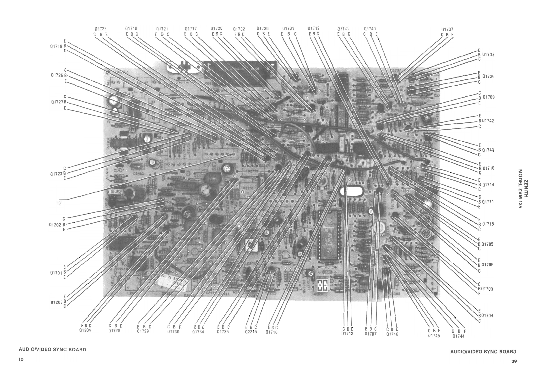
AUDIOIVIDEO
10
SYNC
BOARD
C
BE
01713
E B C
01707
C B E
Q1745
C B E
01744
AUDIOIVIDEO
SYNC
BOARD
39
Page 16

A
B
C
D
E
F
G
H
K
L
M
D
J
s::
o
ON
mm
r"'Z
N-
<-I
s::~
.....
w
U1
AUDIOIVIDEO SYNC BOARD
12
o
p
Q
R
S
T
A Howard W. Som s
4 I 5 I 6 I 7 I 8 I 9
[!liU,i';m-.
Ph
oto
110
III
112
13114115 116117118 19120
121
1221
23
241
25126127128 T
o
p
Q
s
AUDIOIVIDEO SYNC BOARD
37
Page 17

_
.......
12
,
9V
....
II!II
....
3:
o
eN
mm
r"'z
N-
<0004
3::::I:
A
Howard
W. Sams
[iil.Jillii,t.i3i
Photo
MAIN BOARD
13
Page 18

12.0V
B
E 02102
C
MAIN
14
BOARD
A Howard W. Sams [
128V(A)
..
'·13-iil·f.S3i
Photo
26
9V(A)
CBE
03202
-
186V
Page 19

1
2
3
4
5
6
7 8
9
10
11
A
B
C
D
E
F
G
H
A
B
C
D
E
F
G
H
0
3:
-t
...-..
•
N
3:
0
ON
mm
'-z
N-
<-I
3:~
~
Co)
U'I
J
K
1 2 3 4 5 6 7 8 9
A H
owa
rd W.
Sams
li§ill.nn
10
••
Pho
11
to
J
K
MAIN
BOARD
15
Page 20

Em
VIDEO OUTPUT BOARD
16
A
Howard
W. Sama
(,,,,,;illii·i3M
Photo
Page 21

3:
o
eN
mm
""z
N-
<-f
3::::I:
~
w
U1
A Howard
W.
Saml
@'·Gilii
,'.!3' Photo
HV/HORIZONTAL SWEEP BOARD
17
Page 22

HV/HORIZONTAL SWEEP BOARD GridTrace LOCATION GUIDE
1- 8
RX3
C2
131
C21
52
C3
202
C32
03
C
32
06
C320
7
C3209
C32
10
C3211
C3212
C32
13
C32
14
C32
16
C3217
C3218
C3233
C3
244
C3261
C32
76
C3277
CR3202
CR3203
CR
3204
CR32
05
CR32
06
CR320
7
C
R32
08
CR32
09
CR32
10
CR3211
CR
3276
CX32
04
CX32
05
CX3219
CX3
229
E
3251
I
L3207
L322
0
LX3261
L
X32
62
Q32
04
Q3206
Q3
209
QX3202
QX320
7
R2105
R21
10
R2111
R3
207
R3209
R3219
R3224
R322
5
R3226
R322
7
R322
8
R3242
R3243
R3244
R
32
50
R3251
R3261
R3262
R32
63
R32
64
R32
79
R3282
R32
99A
R32
99B
RX3206
RX3208
RX3210
R
X32
11
R
X321
3
HV/HORIZONTAL
CCG-
D-4
F
-8
G
D-5
E-5
D
-3
E
F
-4
E
F
-3
G-
F-1
N-9
J-1
8
-8
K-8
D-9
E- 7
H-8
C-7
0GE- 3
G-
G-9
E-6
F-6
E- 9
G
1
J-7
0-9
AE
-4
G-6
A- 5
AGE
-6
F
-2
E- 2
D- 7
C-6
CC-8
GE-8
G-8
F
-2
E
-1
E
-3
F
-4
G-
F-1
G-
M-
H-9
AA
-4
A-1
A-1
H
-9
E-9
F- 5
L- 1
L-1
J
-8
E- 7
L-8
C- 5
C-5
7
RX32
8
7
-4
-4
-4
2
14
RX32 15
RX32
16
RX321
7
A
B
c
5
5
1
D
E
-4
-2
7
2
8
8
F
G
H
J
7
K
10
1
1
9
L
M
N
o
SWEEP BOARD
C- 6
C-
6 13205
G-6
1 2 3
1 2 3
218
RX3235
TP3
A Howard
W . s
E- 8 T
E- 5 TX
C-1
0-1 389
456
456
om
slrl;UtJi;lJ;W
X3204
3251
2A
3
Photo
K-
6
K-10 353
C-4
G-3
3R3
7 8
7 8
9
9
0-
3
0-1
10
10
A
B
c
D
E
F
G
H
J
K
L
M
N
o
18
Page 23

ro
s:
o
eN
mm
r-
z
N-
<-f
s:::I:
......
Co)
C11
A How ard W . Sams
[iliI·I;i1i1·f.i3i
Photo
--
CONTROL BOARD
(j)
>
.,...-
.,...-
19
Page 24

ZENITH
PART No.
3-142-01
103-142-01
10
103-254-01
1
11
01
-
-
3-254
103-336
103-142-0
10
1
-13
1
103-142-0
103-30
01
-
03-254-01
1
103-254-01
103-142
1
-0
2
79-14
2
-14
103
103-
103-142-01
-01
103-142
01
142-01
3-254-
103-
10
103-142-01
/177
62
WORKMAN
DATA
RCA
REPLACEMENT
PHILIPS
NEW·TONE
GENERAL
WEP10
/177
PART No. PART No.
SK9091
77
I
ECG
ECG
177
NTE
PART No . PART No.
NTE
PART No.
ELECTRIC
GE-300
16
158/1
P
WE
WEP1062/177
1/177
SK3313/116
SK909
I77
G
EC
ECG116
177
NTE
0
30
GE
GE-504A NTE116
16
09/139
412/5011
1
WEP158/1
WEP1062/1 77
WEP11
WEP
1A
6
1
11
3/
K5A6/50
SK33 1
SK9V1/139A
S
SK9091/177
A
11
77
ECG139A
ECGI
ECG116
ECG50
E116
E 177
NTE139A
NT
NT
NTE5011A
. 1
4A
GE-300
GElO-9
GEZO-5.6
77
6
11
062/1
I
WEP
WEP1062/177
77
SK9091/1
77
ECGI
NTEI 77
GE-300
WEP158/
SK9091/177
SK3313/116
16
77
I
1
CG
CG
E
177 E
116
NTE
NTE
04A
-5
GE
GE-300
WEP158/116
WEP1062/177
WEP1062/177
WEP1415/5014
177
SK9091/
SK3313/1 16
SK9091/177
SK6A8/5014A
4A
1
I77
ECG50
ECG
ECG116
6
177 ECGI77
I77
E
TE11
NT
N
NTE5014A
NTE
4A
00
300
GE-3
GElO-6.8
GE
77
177
62/1
0
1062/
WEP
WEP1
77
1/177
SK9091/1
SK909
77
77
CGI
E
ECG1
77
I77
NTEI
NTE
-300
GE-300
GE
62/177
0
WEP1
WEP158/116
/177
9091
SK
SK3313/116
16
1
ECG
ECGI77
116
TE
N
NTEI77
0
-504A
GE
GE-30
Description
and
Number,
Part
Model,
state
,
parts
ordering
PARTS LIST AND DESCRIPTION
When
~
MFGR.
TYPE
ITEM
SEMICONDUCTORS (Select replacement for best results)
PART No.
No.
No.
- 01
103-254
103-142-01
103-142-01
42
142
TI1
ITI
I
H28404
01
01
17
1703
hru
t
CR
CR13
CR
CR1714
1 GE-50
254-0
3-
3-301-13
03-336-11
10
10
1
103-142-01
42
739A
TI1
N4
I
1
M33611
15
17
1722
I 724 TZ4E254
CR
CR
CR
CRI725
42-01
1
3-
ITT1 42 10
I726
CR
thru
1
3-254-01
3-142-0
10
10
254GI
CR2104 R142
CRI728
CR2105
1
1 GE-50
01
-
03-142-0
03-254-0
1
103-142
103-279-14
42
TI1
I
MK279-14
CR2199 R142
CR2106, 7 H254E4 1
CR2108
CR2254
thru
CR2256
01
3-142-
03-142-01
10
1
142
TT
I
01
r u
CR25
CR2503A R142
CR2503
th
1
3-254-0
10
GI
06
504 254
hru
t
CR2
CR25
103-142-01
42
R1
4
CR251
Page 25

- 01
-142
3-142-01
ZENITH
PART No .
10
103
62/ 177
10
1062/ 177
PART No.
WORKMAN
EP
W
WEP
01
2-01
14
3-
3-142-
10
10
77
1
/177
621
P 1 0
WE
WEP1062
2- 01
-14
3
10
77
/1
062
EPI
W
5
-330
03
03-30
1
1
103- 330
525
2/ 177
06
10621177
EPl77/
W
WEP
WEPI
-Dl
84
3-309
03-2
1
10
019
06
/5
I72/5
1420
WEP
WEP
01
-295103
F- 16147
/177
62
10
WEP
1
1
42-0
1
3-295-0
03-
10
1
103 - 326
/177
/177
/ 506
62
62
l72
10
10
WEP
WEP
WEP
-1 42-01
03
1
WEP1062/ 177
1
01
-0
-142
3-254-
103
10
177
/ 1 16
62/
P158
WE
WEP10
1
4-0
25
310
/116
58
P1
WE
326
103-
/506
WEP172
330
3-
03-330
1
10
7
77
17
62/
WEP10
WEPI 06211
6
15-D6
15-0
3
3-3
310
10
06
5-
1
3-3
10
3-284
10
06
72/5
WEPI
3-254-01
10
P158/ 116
WE
ption
ri
sc
, and De
mber
PS
REPLACEMENT DATA
LI
PHI
NEW·TONE
GENERAL
.
.
No
MFGR
PART
177
RCA
PART No.
9091/
SK
NTE ECG
PART No . PART No.
PART No.
ELECTRIC
177
11 77
91/
91
90
K90
S
SK
I77
G
EC
ECG177
ECGI77
E 177
E 177
TEI77
NT
NT
N
0
-300
-30
C£
C£
GE-3 00
1
01
-0
-01
42
142-
-142
3-
03-1
103
1
10
1 177
1 1 177
091
909
K9
SK
S
ECGI77
ECGI77
177
E 177
TE
NT
N
-300
-300
C£
GE
1
01
-0
42
03-1
103- 142-
1
77
/1
/ 525
25
9
SK3
SK9091/ 17 7
SK9091
ECG525
ECGI77
ECGI 77
77
525
EI
E 177
TE
N
NT
NT
00
00
-3
-3
GE-533
C£
C£
0
305
33
310
103- 330
103-
2
/55
00
90
SK10A/501 9A
SK
G552
EC
ECG5019A
52
5019A
E'5
TE
NT
N
l 0
11
- 5
ZD-
C£
GE
09-01
3-3
103- 284
10
52
1177
1/ 177
9000/5
909
)
7(1
F-1 614
SK
SK
2
I77
G
CG55
E
EC
552
E
NT
NTE 177
11
- 300
C£-5
GE
-01
295
310
103-326
SK9091
ECGI77
NTEI 77
0
30
GE-
01
214
310
SK9091/177
ECG177
77
EI
NT
GE-300
1
-0
295
103-
/ 177
091
SK9
GI 77
EC
177
TE
N
-300
GE
-{)1
142
310
16
13/1
SK33
SK9091 I 177
6
I77
11
ECG
ECG
NTE116
GE-504A
01
254-
310
16
/1
313
SK3
177
NTE
00
-3
C£
1
-0
42
1
3-
10
16
ECG1
16
NTE1
4A
50
GE-
01
3-25410
2
/55
91/177
00
K90
SK90
S
2
GI77
CG55
EC
E
EI 77
E552
NT
NT
GE-511
326
310
091/177
SK9
ECGl 77
77
1
NTE
C£-3 00
GE-300
0
0
33
33
03
03-
1
1
6
06
531
-315-D
310
103
/552
9000
SK
ECG552
52
NTE5
11
- 5
C£
5- 06
284
31
3-
03-
1
10
3/116
SK331
~·lllN:>
6
G11
EC
1300W
6
11
E
NT
GE-504A
01
254103-
H1IN3Z
9£~·WAZ
Model, Part Nu
state
,
rts
PARTS LIST AND DESCRIPTION (Continued)
When ordering pa
.
No
TYPE
No.
ITEM
SEMICONDUCTORS (Select replacement for best results)(cont)
2
14
R
25
R25
C
ITT142
41
5
R2
C
42
TT1
I
CR2543
42
TT1
I
545
CR2
ITT41 2142
3202
CR
8C
4 1
05G1
ITT3304 19
3
330GI
3203
CR
CR3205
CR3202A
ITT
-01
309
5A
320
CR
284
4C
TZ
CR3206
-01
295- 1
295
208
R3
C
CR3207
42
326
4A
TT1
I
TZ
3209
CR
CR3208A
ITT1 42
0
321
CR
54E4
H2
210A
CR3
142
TT
I
11
2
CR3
I
54G
2
A
11
CR32
2K4
H31
B
11
CR32
I
I
30G
3
19
CR32
330 GI
3,24
322
CR
GI
4
CG
5F
1
5-6
315-6C
31
H3
231
232,33
R3
C
CR3234
CR3
4C254
TZ
H284D4
CR3276
CR3235
h)
39-4
26
3
A3
4F
4
TZ
TZ
339G I
217
R3
CR32 14
CR32 12
C
Page 26

ZENITH
1
-01
42-01
3-142-0
103-1
10
103-142
01
-14
79
3-142-
3-2
10
10
9-19
06
7
3-3
3-2
10
10
96
1-
1-105
22
22
1-290
22
-130
221- 179-{)1
221
221 - 264
66
95
21-6
121-9
1
695
121-
19
-10
121
1096
121
121-1084
- 1096
121-695
121
121-1019
121-1096
121-499-01
019
-499-{)1
21-1
121
1
62/177
PART No. PART No.
WORKMAN
WEP10
.
No
DATA
RCA
91/177
PART
SK90
REPLACEMENT
ECG
PHILIPS
PART No.
GI77
EC
E
TON
·
NTE
PART No.
NEW
ERAL
GEN
TEI77
N
PART No.
ELECTRIC
~-300
177
1 77
/5014
415
062/
10621177
10621
P
P1
WE
WE
WEP
WEP1
14A
/177
1/177
6/50
91/177
SK90
SK9091
SK909
SK6A
77
GI
ECG5014A
EC
ECGI77
ECG177
4A
177
EI77
NT
NTE
NTEI 77
NTE501
00
00
GEZO-6.6
GE-3
~-300
GE-3
123 1
31/
WEP1420/501 9
WEP12
231
01
/1
10A/5019A
SK902617
SK
SK3632
23l
701
ECG1
ECG
ECG5019A
231
701
E5019A
TE1
NT
NTE
N
GE-1231
~ZO-10
736/123A
WEP
WEP62/159
3AP
159
6/
K346
S
SK3654/1 2
AP
59
1
123
CG
E
ECG
E159
NTE123AP
NT
-62
GE-123AP
GE
EP736/123A
WEP62/159
W
3AP
12
6/159
4/
46
SK3
SK365
AP
23
ECG1
ECG159
123AP
NTE159
NTE
~-82
GE-I23AP
WEP736/1 23A
123AP
54/
SK36
123AP
CG
E
3AP
E12
NT
GE-123AP
9
/15
6/123A
3
62
WEP736/123A
WEP
WEP62/159
WEP7
66/159
34
SK3854/123AP
SK
SK3466/159
SK3854/123AP
9
123AP
159
CG15
CG
CG
E
NTE123AP
E
159
NTE
E
ECG123AP
23AP
159
NTE1
NTE
AP
~-62
~-123AP
GE-62
GE-123
Description
, and
Number
el, Part
Mod
state
parts,
rdering
PARTS LIST AND DESCRIPTION (Continued)
Wh en o
10,)
10,)
SEMICONDUCTORS (Select replacement for best results) (cont)
MFGR.
PART No.
No.
TYPE
.
No
ITEM
1
-01
2-0
- 14
-142
03
1
103
42
142
TT1
ITT
I
CR3401
CR3404
1
-1 4
79
142-01
103-2
103
103-142-0
-14
79
ITT1 42
R142
MK2
06
CR3405
CR34
CR3406
9
9-1
7
308
-
103-2
103
TT
-141
0864
9
27
MK3
204
CR3409
CRX3
I
II
105
-96
122
221
105
221-
221 - 96A05
1
1
45
IC 1
IC130
90
1-2
22
01
0-
-29
221
1
ICl70
0
79-{)1
264
-1
1-
22 1
22
221-13
9-1
264
-130
1-17
1-
22
22
221
401
2376
C3
I
IC1702
IC
95
66
121-9
121-6
966
895
3,4
2
120
Q120
Q
695
21-
895 1
thru
Q1701
Q1707
19
121-1084
121-10
1019
1064
thru
thru
706
717
Q1
Q1
Q1716
Q1722
6
09
1
112
121 - 1096
96
1096
10
Q1726
QI723
121-1096
121-695
1096
1064
895
Q1727
QI726
-499-{)1
21-1019
1
1 21
1019
499-1
u
0
thr
,3
Q1733
Q1731
Q1729
1
19
1-499-{)
12
121-10
1
9-
1019
49
734
Q1
Q1735
Page 27

ZENITH
WORKMAN
-1084
121
PART No. PART No .
51
1019
1-5
21-
12
1
29
/2
2/159
6
WEP
WEP956
95
-8
121
/ 123A
36
P7
WE
-895
21
1
121 - 1019
A
123
59
/
36
WEP62/1
WEP7
1072-01
- 975
1-
-l0896
21
12
1
F
1
/29
P736/123A
WE
WEP780
064
1
121-699
121-
P62/159
WE
WEP62/159
551
-1019
21
121-
1
229
/159
6/
95
P
WE
WEP62
-1019
121
019
551
-
- 551
121
121
12 1- 1
/229
561229
956
9
WEP
WEP
WEP62/159
WEP62/159
1019
1019
-
1-
21
1
121-966-02
12
159
5/152
/159
4
62/
P62
EP
WEP7
WE
W
121-499-01
FI2737
WEP736/1 23A
37
3
0
1034
97
-
21-1059
121-
121
121-1
1
P702/171
P62/159
EP62/159
EP702/171
WE
WE
W
W
ion
Descript
DATA
RCA
PART No.
REPLACEMENT
ECG
PHILIPS
No. PART No.
NTE
PART
NEW·TONE
No.
PART
GENERAL
ELECTRIC
AI229
6/ 159
S1<346
SK3246
9
9
ECG15
ECG22
229
TE
N
NTE 159
GE- 82
GE-6 1
AP
9
23
466/15
K3
S
SK3854/1
P
3A
59
CG1
ECG12
E
159
NTE
NTE123AP
GE-123AP
GE-82
23AP
0/291
854/1
SK3
SK344
23AP
291
ECG1
ECG
NTE291
NTE123AP
P
302
GE-
GE-123A
AP
159
SK3466/
SK3466/159
S1<3854/12 3
G123AP
ECG159
ECG159
EC
3AP
159
159
12
NTE
NTE
NTE
3AP
GE-82
GE- 12
GE-82
1229
466/159
K3
SK3466/159
SK32 46A
S
159
ECG
ECG159
ECG229
159
E229
NTE159
NT
NTE
-61
GE-82
GE-82
GE
9
229
246A/
466/15
K3
K3
S
S
ECG229
ECG159
159
229
TE
NTE
N
GE-82
GE-61
9
/229
246A
466/15
466/159
K3
K3
SK3
S
S
ECG159
ECG159
ECG229
59
229
E 1
NTE
NT
NTE159
-82
GE-82
GE
GE-61
93/152
SK38
ECG152
152
NTE
-66A
GE
71
/1
01
466/159
SK3
S1<3466/159
SK3854/123AP
SK32
S1<3201/171
AP
3
159
ECG
ECG12
NTE123AP
AP
23
GE-1
ECG171
ECG159
9
15
E159
NT
NTE
NTE171
GE-82
GE-27
GE-82
ECGI71
171
NTE
GE-27
~·llIl\lO
1300W
H1IN3Z
S£~·WAZ
and
te Model, Part Number ,
sta
dering parts,
or
PARTS LIST AND DESCRIPTION (Continued)
When
MFGR.
PART No.
No.
TYPE
No.
ITEM
SEMICONDUCTORS (Select replacement for best results)(cont)
-1019
1-895
21
121-551
121-1084
1
12
51
019
1
1084
5
895
739
736
1738
01737
01
01
0
019
1-1
12
1019
u
hr
t
43
1740
0
017
121-895
895
thru
746
744
01
01
-01
75
072
-1
-9
21
1
12 1
F-l0896(2l
ITT975
1072-1
02 103
02101,2
064
1-1
12
4M
106
021 04
9
1-69
12
99
6
2215
0
1
019
- 1
-55
121
121
1019M
551M
2502
0
02501
019
1
551
-
21-
121
1
551M
Rl019
503
02504
02
1-551
121-1019
12
121-1019
M
191~
1 0
551
Rl019
7
506
02 505
0250
02
019
-1
1-966-02
2737(2l
12 1
12
F1
9M
101
TZ966-03
200
2508,9
0
03
1
34
99-0
1-10
12
121-4
-01-G
34
TZl0
R499
03201
03202
1-1037
1-1059
121-973
12
12
9M
I TT973
105
TZ1037
3203
3206
0
0
03204
I\.)
Co)
Page 28

I
REPLACEMENT DATA
PHILIPS
NEW·TONE
ZENITH
PART No.
121-975
121-1029
PART No.
WORKMAN
'IIEP736/123A
.
No
RCA
PART
SK3854/123AP
ECG
PART No.
ECG123AP
NTE
PART No.
NTE123AP
- 895
-Z9003
12 1
121-1040
P736/123A
WEP740B/165
WE
5/165
11
SK3854/123AP
SK3
CG165
E
ECG123AP
NTE123AP
NTE165
121-895
121
WEP62/159
WEP736/123A
SK3466/159
SK3854/123AP
59
1
CG123AP
E
ECG
59
1
NTE
NTE123AP
95
1-8
121-895
WEP736/123A
WEP736/123A
SK3854/123AP
SK3854/123AP
ECG123AP
ECG123AP
E123AP
NT
NTE123AP
121-1034
12
171
123A
2/
736/
WEP
WEP70
SK3201/171
SK3854/123AP
171
G
EC
ECG123AP
1
NTE17
NTE123AP
F-15684
121-975
36/123A
7
WEP
123AP
SK3854/
3AP
2
CG1
E
NTE123AP
rs.
to
rIbu
t
dIs
local
at
able
l
avaI
No,
MFGR.
PART
ING
RAT
1
9
862-0
7
22-7406
22-7708-0
22-
NP
5V
5V
2
.47 3
)
(1
)(2)
(1
01
35-
479
-13
22- 77
F
180V
0 180V
00
30
DESCRIPTION (Continued)
AND
PARTS LIST
Whe n ordering parts, state Model, Part Number, and Description
~
SEMICONDUCTORS (Select replacement for best results) (cont)
PART No.
GENERAL
ELECTRIC
MFGR.
PART No.
. No.
No
ITEM TYPE
GE-38
GE-123AP
GE-123AP
GE-123AP
-975
-1040
121
121
121-895
040
ITT975
1
TZl029-01
R895
03401
03208
03209
# Q3207
GE-123AP
GE-82
GE-123AP
121-895
121-895
ITT895
986M
R895
Q3404
03402
03403
GE-123AP
- 895
21
1
R895
03405
GE-27
F-15684(2)
121-1034
1034
TZl088
thru
01
05103
051
GE-123AP
sleeve.
part.
bead &
acement
l
rep
ferrite
valent
121-975
i
diode,
equ
l udes
inc
use on l y
I TT975
SAFETY
Assembly,
For
(1)
#
OX3202
~
sInk.
at
he
includes
Assembly,
(2)
No .
TEM
I
normally
are
listed
not
.
No,
MFGR
PART
numbers
Item
RATING
No.
ITEM
ELECTROL YTIC
CAPACITORS
C3429
CX3202 1 50V
#
-02
87-01
740 5
22-74
22-
t'P
NP
5V
2
50V
1
2.2
C1201
C1702
CX3240 17
CX3219 100
#
#
900
406-01
7
7
22-
22-
NP
t'P
100V
35V
4 22
402 1
25
C3
C3
CX3240A
#
t.
par
ent
eplacem
r
6
404-0
7
22-
qu1valent
e
nly
o
NP
use
16V
TY
----
FE
22
SA
- -
or
# F
C3410
y.
d CX3240A.
an
3240
CX
I udes
I udes Lead Assemb I
nc
nc
I
2)
(
( 1) I
Page 29

PARTS LIST AND DESCRIPTION (Continued)
When ordering parts, state Model, Part Number, and Description
CAPACITORS
I
TEM
No
.
C1203
C1204
C1303
C
17
04
C1705
C1706
172
3
C
C2282
C2283
C23
55
C235
6
C23
59
C2376
23
77
C
C2386
C2389
# F
or SAFETY use only
68 NPO
20
N330 50V
47
N750 50V
18
NPO 5
18
NPO 50V
18
NPO
68 NPO
120
N150
22
NPO
51
NPO
33
NPO
I I
NPO
75
N470 50V
68
N470 50V
68
N470
36 NPO
RATING
50V
5%
0V
5%
5%
50V
5% 22-7743-18
50V
5%
50V
50V
5%
50V
5%
50V
5%
SOV
50V
50V
5% 22-7743-25
It-em
22-7633-29
22-7648-23
22-7743-18
22-7743-18
22-76121-30
5%
22-7633-35
22-7743-20
22-7621-27
22-7743-24
22-7621-11
5%
5% 22-7749-32
5%
equivalent
22-7747-33
22-7749-32
CONTROLS (All wattages
ITEM
NO
.
R1400
R1708
R1714
R1832
R1836
R2125
R2390
R2505
R2506
R2516
R2
517
R2527
R2528
R3409
R3
418
R3
441
R7101 Picture
R7
102
R7103 Color Level
R7104
R71
05
R7131 Brigh
RX3499A
RX3499
B Screen
FU
NCTION
Volume
Re
d C
utof
BI
ue
Black L
Reference
Black Leve l
Vert
APC
Red
Re
d Dr
Q-een Cutof
Green Drive
BI
ue
BI
ue Drl
95V Adj
Vert
Horlz
Bl
ack L
Tint
Sh
arpness/Switc
Focus
f
Cutoff
evel
Center
Adj
ust
Cut
of
f
ive
Cutoff
ve
ust
Height
Centering
evel
tness
Cutoff
I ng
f
h
RE
15K
5000
5000
2000
30K
500
10K
800
2500
800
2500
800
2500
lOOK
2000
100
5000
5000
Detent
5000
5000
5000
Detent
5000 63-10857-87
20M
4.5M
numbers
PART
replacement
Y2
SIS
TANCE
not-
MFGR
listed
.
No.
part.
are
normally
ITEM
No.
C3209A
C3210
C3233 .68
C3234
C3242
C3257
C3427
C3450
CX32
II
II
II
II
II
II
II
II
04
CX3205
CX3211
CX3223
CX3227
CX3229
CX3250
CX3258
watt, or less, unless listed)
MFGR.
PART
NO.
63-10772-04 (1)
63-10857-11
57
-31
or
(1
)
@
@
50%
50%
63-108
63-10857-86
63-10857-88
63-10857-15
63-09063-02
63-9023-2
63-10857-12
63-10857-27
63-10857-25
63-10857-26
63-10857-17
63-10857-08
63-10857
63-10750
63-10754
63-10751
63-10751
63-10766-01
(
2)
(2)
available
RATING
470
N1500 5%
82
N750
200V
470 N1500
100
N1500
470
N1500
150
N750
200
NPO
• I
100V
.01
2KV
530
N2200
.01
2KV
530
N2200
.0165
.0047
500V
• I
125VAC
10%
10%
50V
50V
5%
at
5%
5%
5%
5%
3KV
3KV
local dis
5%
10%
10%
NOTES
tributors.
MF
GR.
PART
22-7395
22-5995
22-7128
22-7395
22-5685
22-7395
22-7647-35
22-761 9-41
22-7773-24
23-
22-75
22-7672-08
22-7431-06
22-
01
5854
No.
3:
o
ON
mm
'z
N-
<-I
3:::I:
.....
Co)
CI1
II
For SAFETY
(I)
Number on unit.
(2)
Part
of Horizontal
use
only
equivalent
Output Transformer
replacement
TX3204,
part.
Part
No.
95-3603-01.
25
Page 30

PARTS LIST AND DESCRIPTION (Continued)
When order ing parts, state Model, Part Numbe
r,
and
Description
RESISTORS (Power and Special)
ITEM
No.
RATING MFGR.
PART
REPLACEMENT DATA
No
.
NEW·TONE
PART
No
WORKMAN
.
PART No .
Rl
R2
R1706
#
R1772
R1776
RI779
R17
81
R1782
R1
784
R1785
R1789
R1791
R1799 100
R180
0
R1
801
R1803
R1834
#
R18
34A
#
R2
111
R2112
R2
121
/I
R2122
#
R2299
R2507
R2518
R2529
R3206
24
R32
#
R3225
/I
R32
28
/I
R3231
#
R3239
R32
40
R32
41
R3243
#
R32
44A
R3245
R32
61
R5101
R51
12
R5
113
RX
1457
/I
RX
2101
/I
RX2104
/I
RX2
105
/I
RX3204
/I
RX
3206
/I
RX
3207
/I
RX
3208
/I
RX3209
#
RX321
X3211
R
X3
213
R
RX32
14
X3
215
R
R
X321
RX3217
X321
R
R
X32
19
X3
235
R
X3
240
R
RX3246
0
6
8
#
#
#
#
/I
#
#
#
#
#
/I
#
5'11
5%
5%
1/2'11
1%
1%
1%
1%
'II'll
5'11
'II'll
Me
/4'11
1/4'11
1
/4'11
I'll Car
I'll
I'll
1/4'11
1/4
390
390
2 5%
698 1% 1
698 1%
698 1%
1100
1100
1100
698
27.4K 1%
51.1K 1% 1/ 4
1%
1
100
100 1%
100 1% 1
51
39
3000
10K
150 5% 1/ 2
150 5%
51
1500
1500
1500 2%
12 10% 10
4700
680 5%
680 5%
220
1
1 10% 3
.18
4
2200
47 10% 3'11
47
PTC
3~
2000 5%
2000
2000 5%
82
22
3 5% 1/ 2
3 5% 1
22
5600 5% 1
22 5%
2200 5%
1000
1100 5%
3000 1%
33K
2700
18K
1200
470 5%
2700 5%
4700 5% 1
1100 1% I
10M 10% 1
1.2M 10%
/4'11
1%
1/4'11
1/4'11
/4'11
5% 1/4
5% 1
/2'11
2%
1
2%
1/4'11
1/2'11
5% lOW
2%
1
2%
1/4'11
1/
5%
1
2'11 Metal
2'11
10%
1/2'11
10%
2'11
'11
10%
3'11
10% 10'11
5%
1/2'11
5%
3'11
11
Cold
10% 5'11
3'11
5%
3'11
3'11
5%
2'11 Metal
5%
1/2
',1
/2'11
00 5%
1/4'11
1/
2'11
1/4',1
5%
1/4'11
1/2'11
I'll
5%
1/4'11
2%
1/
5%
1/4'11
1%
1/2'11
1/
1/4'11
'11
/4'11
'11
WIll
/4'11
4'11
'11
/2'11
'II'll
'II'll
'II'll
'11',1
'11',1
Carbon
'11
Carbon Fi
Carbon Film
/2'11
4'11
2'11
/4'11
'll
/2'11
1
/2'11
tal
Oxi
de
Carbon Film
Carbon Film
Carbon Film
bon Fi lm
Carbon F ilm
Carbon Fi lm
Ca
rbon Fi
'11
Carb
on Film
'11
Carbon Fi
Carbon Fi
Carbon Fil
Carbon FIl m
Carbon FIl m
Carbon FI
lm
Carbon FIlm
Carbon FIlm
Carbon Fi
C
arbon
Ca
FIl m
r bon FIlm
Carbon Film
Car
bon Fil
Carbon Film
'II'll
Carbon
Film
Oxi
de 2
Carbon Film
'II
'll
Carbon Film
Film
'II'll
Carbon FIl m
Carbon Fi lm
Carbon Film
Oxi
Carbon Fi
de
lm
lm
Carbon Fi lm
Carbon
Carbon Film
Car bon Film
Carbon
Ca
Film
rbon
Carbon Film
C
arbo
n Fi lm
Carbon Fi
C
arbon Fil
Carbon Film
Carbon
Carb
on
Car
Carbon Fi
Film
bon Film
lm
Carbon
Carbon
lm
lm
lm
m
lm
m
m
lm
6
3-10
271
63-
10442-86A
63-1 0
271
63-
10442-86A
63-1
05
65-
6
3-10934-
63
-10934-
6
3-10934-
63-1
09
36-
63-
10
936-84
63-109
36-
63-109
34-
63
-10935-4
63
-10235-
6
3-10235-4
6
3-10235-4
63
-10235-4
07
97
97
97
84
84
97
8
48
8
8
8
(1)
(1
)
5'11139
5
'1113
HW200
HW051
HW039
63-1 0233-83
63-1 023
6
6
63-10
6
63- 10
63-10460-
3-
10565- 52
3-
10565-52
235-76
3-
102
235-76
3-96
35-
76
50
63-10243-88 H
QW230
QW3
HW11
HW1
QW
QW21
QW2
10
W2
'111
ll
(
(1)
2'11
H
W122
2'11
10'11309
'111
2'110
63-10836-68
63- 7757
63-10422-24
63-1 085 2 (
63-1 0852-01
63-08246
63-1024
63-10
63-1 0
63-1071
778413
63-1 0
63-10840-
63-1 084063-1 0
6
3-80 HW2
430-64
840-
40
0
(1)
444-
86 5
79
79
840-
79
3-10235-46
ll
63-1 0565-32 HW0
63-1 0243-11
6
3-10243-11 HW300
6
3-1023
3-7
5-80
816
6
63-10235-32
6
3-
102
3563-1023
6363-10
6
3-10236
63-10
63-1 02
63
-10
6
3-7
6
3-
80
5-72
778
7
81
8
-08
233-82
36-0
2
810-0
6
770 H
102
35-8
2
63-102 35-88
HW
QW222
H
W2
HW022
QW2
QW2
HW
QW333
QW22
QW3
W14
QW227
QW24
63-10810
6
3-10657-
63-1 0657
-0
04
3
9
10
5
15
215
5
15
'11
012
47
68
168
100
22
39
82
22
3DO
56
22
10
211
18
22-2062
22-2253
22-
2076
22-2076
22-2243
22-2243
22-22
43
22-21
12
22-4092
22-2080
WS1.
0
02
1
24-4
22-2104
FR605
22-40
70
22-2056
22-110
4
22-
2114
22-20
56
22-1 104
2
2-
1096
22
- 1132
7
126
22-1
7
22-2088
22-1106
7
22-11
12
22-217 0
26
# For
SAFETY
use only
equ
ivalent
replac
ement
part.
(
1) Number
on unit.
Page 31

PARTS LIST AND DESCRIPTION (Continued)
When orderin g parts, state Model, Part Number, and Description
COILS (RF·IF)
ITE
No.
M
FUNCTION
MFGR
PART
.
No.
ITEM
N
o.
,
FUNCT
ION
MFGR.
PART
No.
Ll
L2
L1202
L
17
L1702
L1703
L2276
L2277
L2278
L2376
L2377
L23
L2
501
{I
For
01
78
W
idth
Wi
dth
RF
Peaking
Peak I
Peaki
Delay
Peakin
RF
Chroma Tak
RF
Peak I
RF
SAFETY
(120uH)
(120
Choke
ng
ng
Line
g
Choke
Choke
ng
Choke (6
use
only
uHl
eoff
63uH)
equivalent
2
0-4
031
20-40
31
28-390
7-
17
20-3887-16
20-3887- 16
20-3
887-1 6
20-4136
20-3907-21
20-39
19
45-3
080
20
-3887-20
20
-38
31
replacement
part.
COILS & TRANSFORMERS (Sweep Circuits)
IT
{I
{I
{I
{I
{I
No.
D
Y1
L340
2
L
X32
61
T320
1
T3205
TX3202
X3
204
T
TX3251
EM
Yoke
90·
S
we
Wi
dth
Start
Horlz
Re
gulat
Hor
Pi
ncushion
FU
Hor
lz
Vert 27mH
ep
Osc
I I I
Up
Driver
or
I z Outp
ut
NCTIO
1mH
ator
N
PAR
HE
-234HE-23
20-40
20
- 3976
95
-3558-0 3
95
-3344
MF
4-4
26
95-3502-02
95-3603-01
95
-33
89-06
{I
II
{I
{I
(I
GR.
T No.
547
55
L3401
L5
102
L5
103
L5
104
L5105
L51
06
L5107
LX1201
LX1706
LX1785
L
X3262
TX3202A
or
RF
Cho
ke
RF
RF
RF
Pe
Pe
akin
aki
(663uH)
Choke (IOuH)
Choke (
10uH)
Choke ( 1 OuH)
g (8.2uH
ng (8.2uH)
Peaking (8.2uH)
RF
Choke
RF
Choke
RF
Choke
Horl z
LI
LI
REPLACEMENT
IDENTlFICA TION
near I ty
ne Choke
DATA
OTHER
20-3831
20-3907-12
20-3907-1 2
)
20-3907-11
2
0-
20-3907-
12
3907- 11
20-3907-11
20-3801-01
20
- 3975
95-3439
s::
o
THO
RDA
PART
RSON
No .
ON
mm
r""
Z
N-
<-I
s::
::I:
{I
For
SAFETY
FILTER CHOKE
{I
ITEM
LX3202
{I
No.
For
CU
RRE
(Measured)
600m
A
SAFETY
use
NT
use
only equiv
RATINGS
DC
RES.
2.
5
onl y
alent
replacement
INDUCTANCE
(0 CURRENT
1000~)
60mH
equivalent repl
part.
MFGR.
PAR
T No.
95-3501
-02
acement part.
REPLACEMENT DATA
THORDARSON
PAR
NOTES
T No.
27
Page 32

PARTS LIST AND DESCRIPTION (Continued)
When
ordering parts, state
Model
, Part Number, and Description
SPEAKER
REPLACEMENT DATA
MFGR
. QUAM
PAR
T No.
SPI
IT
No.
EM
114" X 3
2
TYPE
1/2"
PM
32
Ohms
49-1332
FUSE DEVICES
TEM
I
NO
.
F
X3201
/I
II
For
SAFETY
ESCRIPTION
D
4A @ 250V
F
as
t-Act 1 ng
use
on
I y equ 1 va I e'
nt
13
6-113-23
rep
I acement
DEV
ICE
part
MFGR.
PART NO.
.
PART
No,
NOTES
NOTES
HOLDER
MISCELLANEOUS
ITEM
No.
CR71
ffi2356
E3251
E5101
E51
02
E5103
L3201
L3207
L3210
L3220
PI
S3201
SOOI
SW1701
SW7501
VI
LED
Crystal
Spark
Spark
Spark
Spark
Degauss I ng
Ferrite
Ferr I te
F
Power Cord
Switch
Switch
Switc
Switch
an
P.C.
P.C.
P.C.
P.C.
P
P.C.
P.C.
Power Cord
Power Cord
Socket
erri
.C.
PART
Gap
Gap
Gap
Gap
Bead
Bead
te
Bead
h
Board
Board
Board
Board
Board
Board
Board
NAME
Co
MFGR
PART
103-15201
.
No.
Power
3.58MHz
Indicator,
NOTES
Red
52-2240-08
52-2240-06
52-2240-06
52-2240-06
II
149-454
AC,
A-11847
Polarized
Power
ite/Green
85-1628
Wh
Composlte/RGB
63-10766-01
M33AAWOOX02
HE-234-547
(1)
or
No! se P
(P
rocessor
art
of Sharpness
Control R7105)
HE-234-455
AudIo/Video Sync
9-230-
5 (1)
Cont
rol
A-9522-05 (1)
204-840-03
zontal
Sweep
HV
/Hor i
9-247A (1)
MaI
9-227-
5A
(1)
204-1023-02
9-155-12
(1)
A-ll056
204-979-01
n
Video Output
VIdeo Ou
tput (A
Width
ssembly Includes
CRT
Socket)
A-l0530 (1)
50-347
125-198-07
78-2993-02
AC, Ass
AC,
CRT
Stra
embl y
In Rei i
ef
(1)
28
Number
on
unIt.
Page 33

PARTS LIST
When ordering parts,
AND
state
DESCRIPTION (Continued)
Model, Part Number, and Description
CABINET & CABINET PARTS (When ordering specify model, chassis & color)
ITE
Top Cover
Bottom
P
Kn
P I a
erfora
ted
ob -On/ Of f
te
Botto
M
m Pl a
te
PART
14-11529-01
12-8215
12-8416
49-1332
No.
I
Knob-Volume
Kn
ob
Assembly-Volume
Knob RetaIning
TEM
SprIng-Volume
PART No.
46-10333
A-08846
80-02166
WIRING DATA
High Voltage Lead
Shie lded
General-use
Hook
........................
-up W
ire
Unshi e lded
••••••••••••••••••••
Hoo
k-up Wi
re
••••••
Use BEL
U
se BEL
Use BEL
DEN
DEN
DEN
No.
9867 (30
No.
8401
8208 (Two-Conductor)
No.
8529 (Sol id)
8522
KV)
or
8421 (Single-C
(Stranded)
Ava
i l
able
Avai l
onductor)
in
13
able
in
Colors
13 Col
ors
:s:::
o
ON
mm
I""'"Z
N-
<-4
:s::::I:
.....
c.:l
U1
29
Page 34

N
_-
....J
,....
,....
(..)
---
~=
01
'
WIDTH BOARD
30
A
Howard
W. Sams
[.11-13111,-,.'31
Photo
Page 35

R3240
s::
o
ON
mm
'-z
N-
<
....
s::X
.....
w
U'I
A Howard
W.
Saml
[!i'·lailiii·s31
Photo
TX3202
HORIZONTAL OUTPUT BOARD
31
Page 36

=-=--E
.....-r-_
B 03204
C
HV/HORIZONTAL SWEEP BOARD
32
A Howard
W.
Saml
(tj1·14iiiili4i
Photo
Page 37

VIDEO OUTPUT BOARD GridTrace LOCATION GUIDE
L5
C510
1 F- l 0
C5
102
C5
103 E- 8 L5103
C
51
04
C5105
C5
106
01
C51
C5102
C5103 G
A-9
K-5
A-7
-7
8
1
-3
E- 7
-3
101
L5102
L5104
L5105
L
510
L5107
05101
05102
JD-2
D
D-3
6
J
C-5
DJ
A-4
-2
-2
-3
05103
4
R5101
R5102
R5104
R5105
R51
06
R5108
5
R511
0
R5111
C-6
H-l
J
-4
L- 7
C-l0
E
-4
E-5
D-3
C-9
R5112
R5113
R511
R5115
R511
R5120
R
51
21
R51
22
R51
23
R5
C- l
C-4
4
9
A-8
8-8
C- 8
-2
J
C-5
DA-
6
8
124
R5125
5
A2
5C
2
5H3
5X3
K-7
8-8
A-I
-ll
D
G-2
F-2
I
A
B
C
D
E
F
G
H
1 2
3
4
5
.~
:(
•
6
•••
•
7
• •
8
9
10
11
A
B
C
D
E
F
G
H
3:
0
ON
mm
'-z
N-
<0004
3::1:
.:..
eN
U1
J
K
L
1
2
~2':;
5"2IJ
r 3
rr {
12
4
5
A Howar
d W.
6
Sams
lco);jj.UtJillW
7
8
Photo
9
J
K
L
10
VIDEO OUTPUT BOARD
11
33
Page 38

MAIN BOARD GridTrace LOCATION GUIDE
C
C2101
C2
102
C2103
C2104
C2
105
C2106
C2107
C2
110
C2111
E- l
E-7
AE
-9
A-9
AA-8
AE
-6
D
-6
5
7
7
C2176 C-8
C2504
C3201
C
3205
C3206A
C320
7A
C320
9A
C3234
C3236
C324
2
C32
46
C32
47
1-1
F
-3
J-7
K-
C- 6
H-7
G-5
F-6
H-6
1-6
D- 5
7
C3249 A-l0
C325
1
C3252
C3253
C3254
C3256
C3257
C34
02
C340
3
C34
04
C3405
C3407
C3409
C3410
C3411
C341
2 8-5
C34
13
C3414
C34
16
C34
19
C3420
C3421
C3
422
C3423
C3424
C3425
C3426
C3427
C3428
C3429
C3430 8
C3431
C34
34
C3436
C3450
C3461
C346
2
C
R2104
0:12
105
R21 06
C
0:12107
CR2108
CR2199
CR2501
CR2502
CR2503
0:I2503A
CR2504
0:12505
CR2506
0:12514
CR2525
-l
E
E
-l1
E-
0-11
G-6
HE
-4
C-5
C-6
A-3
D
-6
0-4
C-6
G-8
A-4
0-3
8-5
-4
C
G-l
C-2
-2
C
C-l
C
-3
8-3
B-3
8
-2
B-2
D-2
-3
A
-2
0E
-4
H-l
E-2
E- l
A8-9
A-
8
E
-8
A
-4
8-8
1-4
1-3
1- 1
1
-4
J-5
J
-4
J
-2
1-3
1-1
l0
8
5
5
CR2541
CR2543
CR2
545
CR320
2A
C
R3205A
CR
3208A
CR3210
A
CR3211A
C
R3214
CR
321
7
CR3
219
CR3223
CR
3224
CR
3231
CR32
32
CR3233
CR3234
CR
3235
CR340
1
CR3404
CR3405
R34
06
C
0:13408
CR3409
0
CX32
50
CX32
58
Dl
E
FX
3201
1C340
1
L
2501
L3401
L3402
L
X32
02
0
2101
02102
02103
02104 F-5
02501 H
02502
02
503 H
025
04
02505
02506
02
507
02
508
02509
03200 F
03201
03202
03203 1
034
01
Q3402
03403
03
40
4
03405 H-l
R21
02
R2103
R2106
R210
7
R2108
R2109
R2110A
R2
111A
R2112A
R
21
13
R2114
R2115
R2116
R2117
R2118
R2119
R2
120
R2122
1- 5
1-4
-2
1
F
-3
G-3
H- 8
J-8
J-
8
G-5
H-6
-9
H
-4
E
H-9
l0
EE
-l1
-9
E
E-l0
H-
8
C-
5
C-2
A-4
A-3
0-2
F
-l
-l
H
J-
l0
D-
l
-2
H
J-l1
8-4
H
-5
D-4
0-1
8-10
E
-6
C
-8
D-6
-4
J
-4
-3
J-3
H-2
J-2
J-5
-3
J
J-2
-3
G-3
J-
7
-7
F-l
E
-3
G-
l
G-2
A-8
A-5
A-4
E- 8
-8
E
8-8
B-8
8-8
B-8
A-
9
A-6
E-7
E
-6
E-6
D-6
-5
0
F-6
E-5
R2123
R2125
R2126
R212
R2128
R2129
R2502
R2504
R2505
R2
R25
R25
R2510
R25
R2512
R2
R2515
R2516
R2
R2518 H
R2
R252
R2523
R2524
0
R2526
R25
R2
R2529
R2530 1
R2532
R2534
R2538
R2539
R254
R25
R2544
R2546
R25
R2549
R2550
R2552
R2554
R
R3202
R3203
R3205 F
R3206
R3210
R3212
R3213
R3214 1
R3215
R3216
R321
R
R3219A
R322
R
R3233
R3234
R3239A
R3241
R
R3245 1
R3260
R3
R3262A
R34
R3402
R3403
R3404
R3405
R3406
R3407
7
506 1
07
08
11
513
51
7
519 1
1 J
27
528 1
0 H
42
48
3201
7
321
8
2 8-7
3231
3244A
26
1A
01
E-5
F
-8
F
-9
G-9
G-9
E
-8
H
-5
1
-4
J-4
-4
H-5
1-4
J-5
J-5
G-4
-3
H
1
-3
J
-3
1-3'
-3
-3
-3
H
-2
H
-2
1-1
J-l
-2
1-2
-2
J-2
J-5
H-5
H-3
-2
1-5
1-4
J
-2
J
-3
J-2
J-5
J-4
J-2
G-3
G-3
G-3
-4
G-4
1
-8
1
-7
1-6
-6
J-6
J-6
J
H-7
J-6
F-4
1
-6
H-6
AD- 9
J-9
J-7
1-7
1
D-4
D-4
8-4
C-5
A-5
C-5
8-6
R34
08
R3409
R341
0
R34
11
R3412
R3413
R3414
R34 15 8- 5
R3417 8-5
R3418 G- 7
R3419
R3420
R3421
R3423 8
R3424 G-8
R3425
R3428
R3429
R3431
R3432
R3433
R3
434
R3435
R3436
R34
39
R3440
R3441
R3
442
R3443
R3444
R3445
R3446
R3451
R3
452
R34
53
R34
61
R3462
R3463
R34
65
R346
6 G
R346
7 G-2
R34
68
R3469
R3470
R3471
R3472
R3473
R3474
R3475
RX2101 8
RX210
4
RX2
'105
RX32
-6
46 F-l0
T32
01
T
X3202A
X H
Y A-I
2A
5
285
2M
II
3D3
3F
3
3G3
-9
3R8
358
3
T8
-8
3V3
31>13
5M
C-6
F
-7
-7
8
8-5
8-6
8
-6
8-6
H
-7
A-6
D
-3
-5
C
-3
E
-3
E-4
E-3
C-3
8-2
8-2
C-3
8-2
A-2
A-3
8-1
A-2
C
-2
A- 3
C-6
E
-2
H-l
-l
J
0-2
F-2
E
-2
E
-3
F
-l
-2
F-2
-l
F
G
-2
G-l
-2
H
H-l
A-2
C-2
-8
D-7
D- 7
G-l0
J
-l0
-4
K-
3
K-4
A-6
G-7
K-5
D
-8
K-l0
K-9
K-8
D
-l1
D
-l0
D-5
34
Page 39

MAIN BOARD
35
Page 40

AUDIOIVIDEO SYNC BOARD GridTrace LOCATION GUIDE
J-
Al
C12
01
C1
203
C1204
C1
206
C120
7
C1302 L
C1303 0
C1304 L- 2
C1452
C1456
C1459
C1460
C1461
C1462
C1
463
C1467
C1468 F
C1701
C1702
C170
3
C17
04
C170
5 P
C1707
C
17
08
17
11
C
C17
12
C1718
C1719
Cl720
5-1 9
M-
NM-8
0
CR1714
CR1715
1-5
17
CRI722 F
CRI72
7
CRI725
-4
CR17
-l
CRl727
-3
CR1
CR225
E-
2
CR2255
K-2
K-3
H-4
1-3
Q-4
G0
KL-26
N0-22
CR2256
C
OB25
El
FIG
IC
4
I
-3
IC
-3
IC17
9
IC
L
2
L1701 0-23
-22 L 170
KGHH-19
E-28
L-28
L1708
14
L2276 0-12
21
L2277
22
L
L2376
L2377 0-10
1-1 1
L2378
R23
nOl
C14
1701
2376
12
227
728
02
Cl721 0-12 L2379
Cl72 3
Cl
724
C1
786
C1858
C22
15
C22
51
C22
57
227
8 P
C
C2281
K-
J-
R
H-2
T-1 5
N-15
0-
P
28
17
-22
16
-14
-17
2
L2382
LX120
L
X170
LX1706
01202
01203
01204
017
01
01702
C2282 0-1 8 01703
C2284
C2354
C2
355
C23
56
C2
358 R-26 01708
C2359
C2362
5
MLM-
K-2
M-23
C2376 5-1 1
C2377
5- 11
-13
19
20
22
0
01704
01705
01706
01
707
01709
01
710
0171
0171
C2378 5-1 8 01713
C2379
C238
1
C23
82
C2384
C2385
C2386
C23
88
23
89 R- 22
C
C2
390
C2393
CR1301
m 1701
CR170
3 F-25
CR1704
CR1705
m1 706
R1707
C
CR1708
CR1709
CR1710
CR1711
m17
12
CR1713
Locat
*
ed
other
R-1 8
0-
16
Q-
17
5-
24
5-24
T-20
5-21
N-I
M-
24
M-2
M-8
H-27
F-25
-2
H
F-
24
H
-24
J-2
J-27
J-23
J
-24
J-22
side
O
6
6
171
0
01715
Q17
0
171
01718
17
0
01722
01
723
Ql726
01727
01728
01729
17
0
0
173
01732
01733
01
734
01735
17
0
01
737
01
738
01739
01740
of
4
26
4 5
56
51
02
2
8
1
5 L
1
2
4
16
7
19
30
1
36
boar d.
22
L
-ll
-20
C-22
C-22
P-27
P-27
0-27
-14
R-13
R-
14
K-2
A-l 0
E-5
H-
l0
P-2
G-3
E-21
B-21
0-
19
M-6
P
-22
R-22
N-17
P-
13
R-13
5
-22
R-18
T
-22
N-8
-27
J-l0
L-5
M-6
N-6
N-3
M-26
M-25
0-25
L
-26
L-25
K-2
G-2
-24
F
G-24
J-24
K-24
J-21
1
-27
J
-2
J-21
0-1 5
E-15
1-14
1-15
G-8
G-l0
F
-6
J
-l1
1-15
1-16
C-18
0
-18
18
FH
-18
1-19
8-1 7
8-25
8-26
C-26
0-2
01741
Q1742
01743
01744 P-24
01
745
Q1746
02215
206
R1
R1207
R1209
R1211
1
R1212
R1213
R1214
R1216
R1217
R1301
R1302
R1303
R13
04
R1452
R1453
R1454
R14
55
R145
6
R1463
R1464
R1701
R1702A
R1702B
R1703
R1704
R1705
R1706
R1707
R1708
R1709
R1710
R1711
R1712
R1713
R1714
R171
5 0-26
R1716
4
R1717
1
R1718
R1719
RI720
RI721
R1722
RI723
Rl
724
5
RI725
17
26
R
Rl727
Rl728
Rl729
17
30
R
R1731
R1732
R1733
R1734
R1735
R1
736
R1737
R1738
R1739
R1740
R1
741
R1
742
R1743
R1744
R1745
6
R17
46
0
-25
F-26
G-28
0-24
R-24
R-15
0-8
L-7
K-4
L
-7
N-6
N-4
N-4
N-5
0-5
N-l
N-3
0
-4
M-3
C-2
J-2
K-2
1
-2
0-3
F
-2
E
-3
N-2
L-6
L-6
K-6
K-5
N-2
L-l0
P-26
N-28
M-26
P
-26
K-l1
N-26
P-25
0-28
P-25
0-26
P-13
J-26
HP-22
J
-28
J
-23
H
-26
0-26
J-25
J-22
-24
H
0-27
K-23
E
-12
E-l1
H-13
0
-13
E-13
H
-14
F-13
E-13
E-13
F-13
G-13
G-14
H
-13
1-13
H
-13
1-12
R1747
R1748
R1750
R1755
R1756
R1757
R1758
R1759
R1760
R1761
R1762
R1763
R1764
R1765
R1766
R1767
R1768
R1769
Rl770 K-14
Rl
772
Rl773
RI775 F
Rl776 E
RI778
Rl779
R1780
R1781
R1782
R1783
R1784
R178
5
R1786
R1787
R1
788
R1789
R1791
R1792
R1793
R1794
R1795
R1796
R1797
R1799
R1800
801
R1
R1803
R1804
27
R1805
R18
06 H-25
R1807
R1808
R1810
R1811
R1812
R1815
R1816
R1817
R1
818
R1819
R1820
R1821
R1822
R1823
R1824
R1
825
R1826
R1827
R1830
R1831
R1832
R1833
IR1834A
R1834B
R1835
F
-12
G-12
H-12
E-9
G-9
G-7
E-l0
G-
9
G-9
E-9
G-
l l
E-l1
E-IO
H
-7
H
-8
K
-17
K-
15
K-18
C-
17
0-17
-16
-17
H-17
F-1
0-22
0-22
E-22
H-21
F
-22
1-18
J-2
F
-22
G-26
H-18
J-17
G-18
E-1
F
-18
B-16
C-17
9
-18
8-19
0-19
C-22
B-22
H-27
J-28
J-
26
H
-25
C-l0
J-7
B
-24
C-27
C-27
9-2
C-27
E-26
E
-27
F
-25
F-27
H-28
C-24
0-27
0
-24
E-26
0-13
1-16
J-19
K-18
H-23
1
-23
E-22
R1836
R1837
R1838
R1839
R1840
R1841
R184
2 0-7
R1843
R1844
R1847
R1848
R1849
R1876
R2215
R22
16
R225
1
R2253
R2254
R2255
R2257
R2276
R2278
R2285
R2286
6
R2
287
R2288
R2297
R2299*
R2354
R2355
R2356
0
R2357
R2358
R2378
R2379
R2381
R2383
9
R238
5 R-20
R2387
R2388
R2389 N-22
R2390
R
X1457*
5WOOl
TP6
TP7
2M
l
4P4
9E4
9F2
7
K-
16
H-19
0-22
0-23
0-23
B-27
-7
E
E-7
F
-7
E-9
H
-6
R-
l1
5-14
R-
15
N-l 1
M-18
0-15
M-15
N-16
R-l1
0-16
P
-15
0-19
P-16
M-1
8
Q-l 1
K-9
L
-19
M-
21
M-21
M-2
M-22
P-18
5-21
T
-26
5-26
R-26
N-22
N-24
K-7
A-7
B-2
B
-4
G-6
B-3
8
-5
H
-5
1
36
Page 41

3:
o
ON
mm
'z
N-
<-f
3:::I:
AUDIOIVIDEO SYNC BOARD
38
A
Howard
W. Sams
[Ii'·Ai,Il
·f.i3i Photo
AUDIOIVIDEO SYNC BOARD
11
Page 42

TROUBLESHOOTING AID
NOTE: Waveforms taken
meter
, no signa
PICTURE
NO PIC,
(TX3204). Refer to "Troublesh
NO PIC, HAS
"Tr
NO PIC, HAS SOUND, HAS RASTE
HAS PIC, NO SOUN
LOW OR
SWEEP
NO RASTER, HAS SOUN
Refer
NO RASTER, NO
NO VE
POOR VERT LIN
POOR HORIZ LIN
OR
SOUND
NO
SOU
ND,
SOU
oub
leshooting"
EXCESSI
to
"Troublesho
SOUND:
RT
DEFLECTION: Refer to
OR
with
tri ggered scope, Keyed-Rain
l.
Controls adjusted for normal operation.
NO
RASTER: Check AC power supply and s
ooting
ND, NO RAST
Horizontal and Video
D:
Refer
VE
BRIGHTNES
oti
FOLDOV
OR
FOLDOVE
ER:
to "Troubleshooti
D:
Chec k HV rectifier (Part of Horizontal O
ng" Horizontal
Refer to "Troubl esho
ER:
R:
" P
ower
Supply and H
Che
ck
Horizonta l
cir
cuit s.
R: Refer
S:
"Trou
Refer
Refer to
to
Chec k Video and Luminance
cir
cuit.
bleshoo
to
"Troublesho
"Tr
Out
put Transformer (TX3204) sources and Video c
"Trou bleshoo ting" Video circuit.
ng" Audio ci rcuit.
oting" Horizonta
tin
g" Vertic
oti ng " Vertical
oubles
hooting
bow
generator. Schem atic voltages measur
our
orizontal circ
ces generated from Horizonta l
uits.
circui
ts. Refer to "Troubl
utput Transformer
l circuit.
al circuit.
circ
uit.
" Horizont
al
cir
cui t.
TX320
ed
with
Out
put
Trans
ircu
it. Refer
eshootin
4)
g" Vide o circuit.
and Horizontal ci rcuit.
digital
for
mer
to
RR
OW PICTURE: Refer to "Troublesh
NA
VERT OFF FREQUENCY: Refer to "Troublesh
HORIZ OFF FREQUENCY: Refer to "Troublesh
SYNC
NO VERT/HORIZ SYNC: Refer
RASTER
YELLOW (NO BLUE): Che
(NO RED):
CYAN
MA
GENTA (NO GREEN): Check Chroma and Green
COLOR (B/W operating normally)
NO COLOR: Refer
NO GREE
NO BLUE: Check Chroma and Blue Ou
NO
N: Che ck Chroma and Gre en
RED:
Check Chroma and Red Outpu t circuits, Refer
Check Chr
to "Troubleshooti
to
ck
Chroma and Blue Output
oma
"Trou
bleshootin
and Red
ng"
Out
tput
oot
Out
Chroma
put
circuits, Refer
ing"
Horizontal circui
ooting"
put circuits. Refer
Vert ical
ooti
ng" Horizontal circuit.
g"
Sync
circ
circuits. Refer
Output
circuits, Refer
circuit.
circ
uits
. Refer
to
to "Trouble
t.
circuit.
uit.
to
"Tro
to
"Tro
"Trouble
to
"Troubleshoo ting" R
uble
shoo
tin
to
"Troubles h
ublesh
ooti
ng" Raster
sho
oting" R
shooting" Ras
aster circuit.
ter
g" R
aste
ooting"
circ
aster
r circui
circuit.
uit.
circu it.
t.
Ras
ter
circuit.
40
Page 43

TROUBLESHOOTING
POWER SUPPLY
Che
ck
the AC Fuse (FX3201). If Fuse FX3201 is open, che
for possible shorts
CR3234), Capacitors
Li
(L3201),
3S
for
tical
Apply 120VAC and
Diode CR3232
120VAC is mi
TX3202, Fuse FX3201, and Conn
120VAC is present , check f
tie poi nt) at pin 2 of Connec
re
check all the parts
If
26.9V at the
at the c
ing,
C3247 and Start Up Tr
s
horts
fro m the Hori
ti f ied by Diodes CR1701 , CR3235, CR3214, CR3208A and
CR3217. If
volta
the Vertical/Horizontal Pro c
are
Switch
shutd
section of the Service
sh
hooting
s
HORIZONTAL
To determine if the moni
voltage on the base of
(OX3202
monitor
to
vice
Check
Conn
Su
In
jec t a horizontal Signal at
put
the sweep
tical/ Horizontal Processor IC (IC3401 ). Check
waveforms and
16
(03209).
Di
odes CR3212, CR3211
(DY1),
(TX3204) and associated
sources developed
load
tified
CR3217. The high v
TX3204 and may be
Poor horizontal li
cond
and CX3227 and Diodes CR3211 B
ne
8.
Use th e " Resis
a shorted Hor i
Output Transistors
the mon
utdown
the
pply"
itor
athode
check
Diodes CR3219, CR3224 and CR3223, El
to
ground. Check the
the
ges and co
missing, check
Trans
own, refer
, refer
guide.
).
The voltage
is in
"High
Informati
for
160V (measured
ector
3V3. If the 160V is
sect
Tr
ansis
tor
oscillator
thru
21
If high
Connect
down
the h
by Diodes CR1701, CR3235, CR3214, CR3208A and
ition of Capacitors C3221 , CX3211 , CX3223, CX3229
at Bridge
C3251
Cho
ke Coil (TX3202) and C
tance
zontal Outpu
(0210 1 and 02102).
check
to
ssing
is
not
cathode
of Diode CR3223.
zont
al
sourc
mponents
istor
(OX3202) to
to
to
shutdown.
Voltage
on.
ion of this T
(03208
components
of I
C3401
voltage is
or
orizont
nearity
for
the
cathode
, check
the vol
the"
3R3, H
the
ment
ioned ab
operating
of
Diode CR3224 and check
ansformer
Output Transfo
e voltages are
associated
essor
tage
the "High Volt age
Inf
ormatio
Horizontal"
tor
the
sho
uld measure
If th e
Shutdown Defeat"
to
roubleshoo
).
If
the
circu
it at pins 23,
and
missing,
Band
orizontal Outpu
compo
fro
m Transf ormer TX3204
al circu it. Check the
olt
age
defect
ive.
or
Rectifier
thru C3253, Degaussing Coil
Measurem
120VAC from the
or
160V (measured
tor
deter
shut
monitor
common
missing
the
associ ated
the
rectifier
foldove
Diodes (CR3231
onnectors
ents
" chart to che
t Transi
stor
of Didoe CR3233. If the
Power
Switch
ecto
rs 3R8 and 3S8.
3V3.
If
the 160V is mi
ove.
when
turned On,
If
the voltages are
(T3201),
source
at the base of the sh
is in sh
base of .the Horizontal Out-
high vo ltage returns, check
Reverse Driver Tran sistor
nents.
check
voltages developed
rmer (TX3204) and rec-
not
regulated, check the
with pins
IC (IC3401
mine if the monitor is in
Shut
n.
If
the
monito
sec
tion
utdown, check
down
Switch
about 0.78V
is in
section
tie
point) at pin 2 of
, refer to
ting guide.
24
and
with
check
Transi s
CR3205,
an
Deflectio
Check
is part
r may be caused by the
d CR3212.
3R8 and
(03208)
).
of
shutdow
of Transformer
or
cathode
(S3201
), Coil
If
to
comm
ssing
check
for 12.
mis
ect
rolytic
for
possi
6 and 8
If al l v
olta
utdow
down Defea
r is not in
this
Trouble-
Transist
if
n, refer
of the Ser -
the"
Power
25
of the Ver-
volta
pins
3, 4, 5 and
tor
03208,
n Yoke
t Tran
sform
for shorted
that
could
sources
thr
Ver-
the
on
for
1V
ble
ges
the
the
ges,
rec-
is
off
If the horizo ntal sweep
osc illator
ck
the a
u
VERTICAL
ck
No vertical sweep.
pone
(02101 and 02102).
c
of
of
t"
or
er
ollector
CR2
and
the Vertical/ Horizont
e
ieflect
ponents
,
If the ver
waveforms and compo
021
sis
and check the Deflec
s-
Vertical linearity or
tical feedback and bias
C2105, C2106, C2131, C2152 and C3277,
for
"Resistanc e Measuremen
changes in feedback and bias
If the ver
n
ponen t s
and
IC34
VIDEO INPUT JACK
Connect a video color bar
Jack
nance IC (IC2376). If the waveform is miSSing, check
voltages, waveforms and
Video
012
C2251
If the waveform is presen t at pin 2 of IC2376,
forms
missing
so ciated
subs
If the
check f
Blue
waveform is miSSing
check
Transis
missing
and
(01745) and
the c
po
Trans
is
po
01711), Green
Am p Tra
circu
djust
nts
10
7,
associated
ion returns, ch eck voltages, wavefo rms and co
01,
tor (02103). Check Diodes CR2105, CR2106 and CR2107
mer (TX3251) and
check
01.
(P7)
Amp
03 and
.
at
titution
waveforms
Cutoff
voltages and
components associated
ollector
nents
isto
still
nents
it at pins 23,
ment of the Hori
Check
as s
ociated
of
Transist or
Pump-Up Transis
asso
cia
tica
l defl
02102
tica
l is o
assoc
the
and check for a waveform at pin 2 of ChromalLumi-
IC (IC1301), Vi deo A
01202
pins 19,
, check voltages, waveforms and
wit
h pi ns
.
or
waveform at
Tra
tor
(01744) and Transi
at
the collec
Transistor
asso
r 01704.
miss
associated with
nsist
with the
If
circu
it ry. In
al
ted wi th
ecti
on does not return, chec k voltages,
and 02104 and th e Retrace Detector Tra
tion
fo
ldover
ff
frequency
iated
with
frequency
), Delay Line (L2276) and
20
and
22
and
are pr esent at pins
nsistor
at the coll
componen
tor
of
Tran s
Amp
istor
with
If
the
check
Transis
ciated
ing,
ors (01707 and 01713).
frequency,
24
and
zont
al Oscilla
voltag es, waveforms and co
Vertical
the voltage is
02102
, check Diodes CR2106 and
tor
(02104
ject
a vertical
Processor IC (IC3401). If the ver
pins
1, 7 and 11 thru
nents associ
Yoke (D
Y1)
problems
cir
cuits.
Check
assoc
iated components. Use the
ts"
chart
circu
, check
pins
10,
of
21
the
s (01702 ,
of
01703. If the waveform is
waveform s a
12,23,24
the sweep
signal to
component
of
IC2376.
23
of
IC2376 and
colle
ctor
01703
ector
ts associated
stor
01702. If the waveform is
Tran
sistor
with
01704
, check voltages and com-
Blue Amp
voltages,
Red Amp
tor
s (01706 and
chec
25
of
IC3401 and check
tor
Output
low
or miSSing at
),
Electro
signa
ated
with Tran
.
can be caused by ver-
Electro
Pincus
to
check
itry r
esistance
the
voltages and com-
and
oscillator
the Video
s associated
mp Transistor
If
the
compone
check
19,
20
and
of
the
and 01704). If the
of Transi
01703, check
Green
Transistor
re
all present
waveforms
Transistors
k the sweep
Coil (L3
402)
.
m-
Transist ors
lytic C2103
l at pin
14
lyt
hi on Trans-
for
25
75
Electrolyt
check
waveforms are
21
Red, Green and
stor
with
Amp Transist
(01746) and
01712
the
14
tical
m-
of IC3401.
sistors
ics
C2103,
poss
ible
s.
of
IC3401
at pin
25
Ohm Inp
with
s (01204,
wav
nts as-
IC2376 by
of
IC2376,
01702,
Red Amp
voltages
missi
ng at
but
video
and com-
(01705 and
) and Blue
of
n-
of
ut
ic
e-
or
3:
o
ON
mm
'-z
N-
<-I
3::1:
......
(0)
C11
41
Page 44

TROUBLESHOOTING (Continued)
VIDEO RGB BOARD
Connect a color
Input
RGB
waveform
form
at the base
waveform
or
all of these
voltages
Blue
01722) or
\'
:')1717,
signal
I f
01731,01732
and 9
forms
ponents
(IC1702) and
If
check
Amp
forms
ponents
01714), Green
A
No red,
the
compo
(05102), Red
01714)
No
If
components
(05103),
01715)
and
Driver (Standard)
01718
path used.
the
wavef orms are
of
the
are
the
waveforms
the
Transisto
are mi
associated
mp
Transistors
Check
waveform
nents
and White/Green
green . Che
the waveform
Green Amp
.
bar
Connector
at
the
base
at
the
base
waveforms
components
Red, Green ar:d
and
and
RGB Gain
missing, check
associated
Transistors
are
waveforms
rs (01714 ,
ssing,
Amp Transistors
(01710 and 0 1716).
for a
is
missing,
associated
Amp
ck
for
is
associated with Green Output
signal
from
(DB25). Use a
of
Red A
of
Green A
of
Slue
Transistors (01720, 0
01719) according
present
01733, check
Control
wit
h IC1701,
01731, 0 17
present
at
the
01715
check
with
waveform
Transistors
Switch (SW001),
a waveform at pin 6
missing,
Transistors (02508,
an RGB
mp
Trans ist
mp
Amp
Trans is
are
missi
assoc
iated w
Blue
Driver (Apple) Transistors
at the base
waveforms
IC (IC1701). If
voltages, wave
at
pins
emitter
and 0171 6
voltages, waveforms
Red
Amp
(01709
at pin 8
check
voltages,
with
Red
(02507,
check voltages,
gen
erat
or
to
scop
e and
or (01731),
Transistor
ng,
to input
Transistor
32
15,
of Red, Green and Blue
Tran
of
(01732) and
tor (017
check wa
ith Red, Green and
terminals
of
Transistors
at
these
forms
and
01733
16
and 17 of IC1701 ,
).
If
these
sistor (01708
and
01715)
the
CRT
waveforms
Output
025
02, 02501 and
of
the
CRT
waveforms
0 2504, 02503 and
check
wave-
33).
If any
veforms
1721
and
and
pins 15,
wave-
and
com
Array IC
.
wave-
and
com
and
and B
socket
Transistor
Socket.
Transistor
the
the
lue
. If
and
and
If
the
raster is
co
mpo
nents associa
(05101) and pin
the
raster
If
components
(05
102)
,
12
-
-
the
If
Yoke (DY1
If the raster has he i
tical", "Horizontal" or "Power
Troubleshooting
AUDIO
Inje
ct
for
sound
for 23,
at pin
shorted
ated
with
trol (R1400).
SYNC
No vertical
and 27
Che
ck voltages
25
thru
No
horizontal
ents
pon
Amp
No
verti cal sync.
ponents
Transitor
is cyan,
associated
and pin 8
raster has a
).
an
audio
from
7V
at pin
10
of
IC1451,
IC1451.
IC1451. A
or
horizontal
of
the
28
of IC3401 .
sync.
associated
Transis
tors
associated
s (03401 and
yellow,
check the voltages
ted
wit
h the Blue
11
of
the
CRT.
check
the
with
of
the
CRT.
keystone
ght
guide
signal
the
speaker
10
of
Audio
check
Check
lso
Vertical/Horizontal
and
components
Check
with pins 25, 26 and
(03403 and 03404).
Check
wit h
shape, check
or
width
.
at pin 2 of C
. No
IC (IC14
Resistor
voltages
check
the
sync.
voltages, waveforms
voltages, wav
pins
1 and
03402
).
, wav eforms
Output
voltages,
the
Red
Output
prob
lems,
Supply" sect
onnector
sound,
from speaker,
51)
. If 23.7V is
RX1
and
components
speaker and Volu me Con-
Check
waveforms
Processor
associated
28
of
waveforms
the
refer
ions
9E4 and
457 and
with
27
of
IC3401,
eforms
IC3401,
Trans i
Transistor
Deflection
to
the "Ver -
missing
check
at
IC (IC3401).
pins
and
and
Sync
and
stor
and
of
thi s
check
check
for
associ-
pins
1 and
com
Sync
com
Amp
1
-
-
No
blue.
Check
for a waveform
If the wav
components
(05101),
01716)
If
for
(01736), IC1702 and
RASTER
Check
If
components
(05103) and pin 6 of
the
ms
the
eform
Blue
and
White/Green
intensity
and comp
the
CRT and CRT
raster
associated
is
associated
Amp
of
onents
is
magenta,
42
at pin
missi
ng,
check voltages
with . Blue
Trans istors (025
Switch
color
is
incorrect, check
associated
associated
voltages
check
with
the Green
the
CRT.
11
09, 02506,
(SW00
with
circ
uitry
and
voltages,
of
the
CRT
, w
aveforms
Output
1).
voltages
Intensity
.
waveforms
waveforms
Output
Socket.
and
Transistor
025
05
and
, wave-
Transis
,
and
Transistor
tor
CHROMA
No
color
when a
monitor
voltages,
2
(I
ch
with Video
(01202,
Crystal
ponents
If there is no col
only color
thru
,4,
C2376). I f
waveforms
10,11,19,20,21,24
the
eck
voltages
Amp
01203
(CR2356) by
associated with
present, check
composite
the
Video
and
wavef
orm
, w
aveforms
IC (IC1301) and
and 01204)
checking the
or
when
video
signal
75
Ohm Input Jack
componen
and
is
pins
using
the
ts
26
of
ChromaiLuminance
incorrect
and components
Video Amp
Check
the 3.
24,
26
RGB
White/Green
is
applied
associated
at pi n 2
58MHz
waveforms
and
28
of
input
and green is
Switch
to
(P7). Che
with
of
IC2376,
associated
Transistors
Osc
ill
and
com
IC2376.
(SW001).
the
ck
pins
IC
ator
-
the
Page 45

RESISTANCE MEASUREMENTS
IT
EM
PIN I
lel301
2702
ICI451
0 0
ICI701
INF
ICI71)
2
INF
IC2376 2000
Pli
l
IS
11K
llK 0
IC3401
PIN
IS
0
l:lF
VI
IT
EM E B
INF
QI202
INF
01203
475 3358 1
20
4
01
0 1793 400 QI730 8120 4346
~1701
9666 7790
01702
9564
~1703
01704 9615
8577
01705
86U7
017UO
~570
01707
01
70;
231a
2325 7590 6590
01709
232'; 7586 b590 01739
01710
1699 8577 6588
017 11
1683 8607 6
01712
1683 8560 6590 01742
01713
01714
115"
1180 9279 6588 01744 22<
OlliS
1177
01716
10
01717
01718
.)
1719 10K
OI72u
01721
01722
QI723
-
01726 0 3876
(1
K 3064
10K
10K
0K
1
IIlK
0
) This reading
MEASUREMENTS TAKEN WITH LOW POWER
P
IN
2
PIN 3 P
INF
7090
INF
IIlF
PIN
3290 102
PIN
3456 313
4283
15K
INF
INF
7500
Pill 17
16
4Jb6
PI;l
16
-
C
~5/0
315
7800
7~00
I
18K
18K
7ull
9247
'J310 6590 01745
3[1)6
J1Jd
4d2U
4810
4840
3854
will
0 01727
3358
01
13"
18K
18~
94
SK
94
94
6590 01737 609
594
659U
94
94
94
94
94
94
4084
407
'1ar
y
depen
IN 4 PI
11K
4790 7052 3470
7340
66~7
lN
PIN
6976 4423 4400 4426 94
21
17
PIN
5316 1
IU2K
a
I
6590
F 1976
PIN
13
K 1036 1
PIN
18
1K
INF
IT
~1728
01729 1000
017
01732
017 J3 INF
01734
QI735
01736
01/38
QI740 566
01711 £35 3 8128
Q17
'~1746
Q211]1
Q2102
Q2103
Q2104
0221 5
Q2501 INF
J
dln
g
upon
ti
lt! conjltl
02502 285
N 5 P
NF
EM
43 2360 8380 6590
IN
6
PIN 7 PIN 8
IN
F 8702
INF
7340
INF
INF
19
PIN
PIll
19
22K
INF
1K
I
INF
IIiF
20
PIN
409
20
PIN
3JK
INF
E
F
F
llF
1430
K 4429
t:le
e
lectrulytlc
10K
INF INF
24K
!UK
10K
!UK
2029
76~
6020
2240
609 1102
1520
714
4404
4],15
5JK
13U5
15~4
0
658d
Jl
IN
IN
7340
IN'
I
294
7521 1102
7848
22~
22
0 1030
348 INf IllF Q5
188
154 4892
INF
on
of
INF
INF
INF
6690
0 1447 4340
21
PIN
10K
PIN
21
0
!N~
B C
17K
III
94
INF
IN
IN
94
INF
94
0 03203
94
3130
659Q
8384
94
94
94
1"F
522b
76
10
0
IN
In the
OHMS
PIN
9
94
I
NF
10
K
INF INF
22 PIN
22
S
F
F
K 0X3202 0
F
I
Clrcult
19K
INF
PIN
18K
F
23
23
IL
.
METER
IN
ID
P
INF
2
16
1218
PIN
24
8194 1450
643
PI:l
24
19~
FIL
IT
EM
02503
02504
02505
Q2506
02507
02508
02509
Q3200
0"201
03202
03204
0320ti 0
Q3207
~3208
03209
03401 1000
03402
Q3403
03404 1000
03405 0
101
05102
05103
PIN II
IN
F
4000
3ti4
6090
INF
PiN
INF
PIN
406
IIiF
E
INF
283
INF
287
IN
F
I
NF
I
NF
INF
0
NF
I
911
407
468
, I
0
196
3950
INF
INF
INF
NF
:IF
NF
PIN 14
3850
PIN
0K
1
449
PIN
1220
INF
PIN
INF
5245
PIN
16K
997
Itl
P
IN
F
16
16
Ib
28
23
15
15
27
27
C
3:
o
ON
mm
'z
N-
<-4
3::J:
11
F
I)
I
PIN 12
I
NF
INF
7580
lIlF
8190
25
PIN
16K
oOK
25
Plil
69K
0
PIN 13
INF
PIN
I
1219
Pill 15
7615
INF
PIN
6690
1218
PIN
26
410
7048
PItl
26
3233
I
B
13
20
0
1498
1321
1369
INF
I
I
970
120
2M
4313
3170
1132
2200
1.
2224
INF
56K
INF
29K
3630
15K
12K
10K
10K
NF
NF
I
0
INF
0
0
U
JOOO(
1<70
INF
IN
32UU
89K(
7860
INF
6
I:lF
16K
9900
7~80
91
677U
INF
I
INf
II J4
43
Page 46

TERMINAL GUIDES
E B C
0
Q
2103
. Q2501,
Q25
03. Q2505
Q250
Q3203. Q34
THRU Q3405
BOTTOM
Q3204. Q3209
QX3202. QX32
BOTTOM
.
7.
THRU
Q2509
01
VIEW
I~
3 0
0
WIRING
VIEW
E B C
0
.
07
VIEW
20
J 0
'
~
• 0
SO
5C2
WIR
ING
VIEW
E B C
0
Q1202. Q1203.
Q17
01 THRU
39 THRU
15
BOTTOM
QI70
Q172
QI73
QI746
VIEW
Q1711 THRU
Q1726 THRU
QI7
Q22
B E C
0
Q
2502.
Q2504
250
6
Q
.
BOTTOM
VIEW
1 0
Iffi
J 0
3S8
3W
3
W
IRI
NG
VIE
W
'"";
~
E B C
Q3
206
F
RONT
VIEW
2 0
3 0
4 0
'
ill
5A2
WIRING VIEW
B E C
G
Q
QI204
9
3
7
I738
BOTTOM
.
J 0 1 0
ill
3R8
W
IRI
NG
VIEW
l§
2 0
SH
3
WIR
ING
VIEW
5 0
4 0
3 0
er'"'"'~
18
1 0
2A
3B9.
3S3
WIRING
B C E
Q2101
Q3200
FRONT
3.
VIEW
. Q2102.
VIEW
1 0
HI
X. Y
W
IRING
VIE
W
2 0
Iffi
J 0
3R3
WIRING
EBC
Q
J202
FRO
NT
I
~
2 0
C ) 0
WIR
ING
VIEW
VIEW
VIEW
[:}
m
WIRING
VIEW
'"'"'
VIEW
r
----'
I
I
,
L ___
PIN
I.
2 •
3.
4 •
5 •
6 • :
IG
F
VIEW
I
I
, I
' '
,0
"
,
,
.J
tQ
E B C
QSIOI
THRU
Q5103
FRO
NT
VIE
W
INDEX
HOLE
2 0
3 0
4 0 4 4 0
'm
E
WIRING
VIEW
"~
2 0
I 0
E2
WIRING
VIE
W
0
1
1m
3F
3
WIRING VIEW
eR
-PN·
os
° T
oy
TX3
204
BOTTOM
VIEW
Z 0
3 0 •
5 0
'm
2B
7
WIRING
VIEW
ML
0
0
K
) 0
2
0
3 0
5 0
6 0
'ill
2A7
WIRING
1 0
J 0
• 0
'
~
5 0
• 0
303
WIRING
VIEW
I§
1 0
3T8
.
3V
0:.
@
VIEW
BOTTOM
10
J 0
'~
• 0
5 0
2B5
.
3G
3
WIRING
VIEW
IC3401
TOP
0
0
0
0
0
0
0
0
a
a
10
II
a
a
12
a
13
OB
25
REAR
10
'Q~--
Q3208
VIEW
1 0
J 0
• 0
m
WIRING
lEW
014
0
15
0]6
017
018
019
020
0
21
022
0
23
024
025
VIEW
2A5
VIEW
IOE
/'
NT
44
1
TAB
I .
1.
'-,
'I]"
• C 9
5
~ 8
• 1
TOP
IC
145
VIEW
IC23
TOP
76
VIEW
Z8
27
16
IS
I'
2J
11
11
10
J9
18
11
16
15
II
10
TAB
,/
1
2
J
2
•
5
•
1
'0"
8 q
IC1301
ICI701,
IC
I702
OP
VIEW
IS
14
IJ
11
II
10
.
I
1
J
•
S
•
1
!
9
JO
11
11
lJ
I'
Page 47

AUDIO/VIDEO
SYNC BOARD
VIDEO
HI-Z
INPUT
GRE
WHITE
SWITCh
CABINET·REAR VIEW
SCREEN
FOCUS
DISASSEMBLY INSTRUCTIONS
CHASSIS REMOVAL
Remove
remove back f
scr
move
two
Audi olVid eo S
from
Remove
bo
Sweep Board an d li
Remove
lour
ews
from
two
screws
screws
tto
hold
Audio
lVi
four
m chassis. Dis
four
scr
ew s
rom
cabin
ync
deo
screws
screws
holding
set. Lay set facedown and remove two
et b
ottom.
holdi
ng
ing rear jack panel and t
Board
Sync Board and remov e board
holding HV/Hor
con
ft
board assembly from cabinet.
holding
cab inet back,
Li
ft ca
bin
top brace
gui
des. Di
nect
all cables from HV/Horizontal
Main Board
et top
to
chassis. Remove
wo
screws
sconn
ect all ca bles
izontal Sweep Board to
to
cab inet
from
SERVICING IN THE FIELD
CRT IMPLOSION PROTECTION AND CLEANING
Imp
losion prot
cleaning
FUSE DEVICES
A
4-
amp fuse is used for AC
Chart.)
WIDTH
The wi dth may be varied by ad
1)
(LX326
ect
acc
. (See Placement Chart.)
ion is an i
omplished
ntegr
without CRT remova
line prote
al
part
of
the
cti
on. (See Placement
jus
ting the wi
picture
l.
lift
up and
set.
holding
from set.
bottom.
dth
Re-
tube ,
coil
Re
lease
two
plastic
retainin g
Dis
connect
cabinet.
CRT REMOVAL
Follow "Chassis Remov
on a s
degaussing coi l
tor
(3S
co
ntr
screws holding cabinet
ic
Ind
Remo
ground
FOCUS
The focus ma y be varied by a
phot
CENTERING
Horizontal centering is
of
the horizontal
Chart.)
Vertical centering is
the vertical centering
Chart.)
all cables from Main Board and
al" procedure
oft protect
3A and 2A3), speaker Co n
ol
Connectors (3S8,
ato r Connector
ve
four
connectors
o,
Cabinet·
ive surface.
Connector
scr
ew s
and
Rear View.)
centering
TP7, 2A7 and 2B7). Remove
front
(Z)
and remove
holding
lift
accomplished
accompl
cont
clips
holding
and lay set
Disconnect
(3T8),
deflection
nector (4P4), front
to
chassis.
CRT to
CRT
from
focus
control
ished by
rol (R2125). (See
Disconnect
cabinet
chassis.
set.
control
by
proper
(R3
441
). (See Placement
proper
Main Board .
lift
board from
facedown
HV anode lead,
yoke
Connec
panel
four
front
(RX3499A)_ (See
Power
from
Disconnect
adjustment
adjustment
Placement
set.
of
~
o
O N
mm
'-z
N -
<-4
~:I:
......
w
U1
-
Coarse ad
the
Plac ement Chart.)
justm
width jum
per to various
ent of
width
may be varied by
width
pOints
Pl
conne
and P
ctin
g
2.
(See
45
Page 48

-~------~~--------~------------------------~--------
+-
CR3219
33061
CR3223
330G
~~>=-3_-;-;;
6
!:I.IV
:-=r--
3 L3401
____
L---
--------
C3247
680}lf
_
__
--~~----
----------
_
______
~--------------------
----------------------
_
___
_
__
_ _
------------_;3 ~RC
_;2
__
~~~~
rn!2.!VCID
SOURCE
E
PRINTED
GAP
C3249
.0047
P
ARK
500V
F
OR
TERMINAL GUIDES
SEE
PAGES
PHOTO
SCJ-£J1A
t:..
1
AKEN
CXttfOH
Tl E
5,
....
CIRCUlTRACE·
TIC C 1
RCU
FRO/1
POI
NT
!TRACE
V
AND
= [[j]
NOTES
III
.4
SEE
TX3204
+---
PAGE
L3220
2
-lf------,
e
CR3120E,,,*C3209A R3205
470pF 820
Y 2
R3210
2
2W
• Rl106
~~~W~--~--~----~--'_6~.~
2
RI711
ISO
e
R3206
12
lOW
10J
C3201
.1
100Y
R499-01C
Q3201
VOlT
e 1064
QI728
11966-03
YOI. T RES
03200
9.
RES
VOl~T~RE~S
_
R3202
120
__
(')
s:
-t
~
•
I\)
!2.IV
--;
SOURCE
!
1.IV
SOURCE
12.OVW
SOURCE
!2.OVCID
SOURCE
!2.0V
SOURC
!1.IV
SOURCE
11.IVW
SOURCE
11.IVCID
SOURCE
-
!8&V
SOURCE
-S.OV
SOURCE
-3.OV
SOURCE
e
R2299
CR3202A
33061
_
__
___
___
__ ~ ___
L2501
____
51
lOW
__________
____
~
_
________
C
1
_ ~ _
_______
_
__
3:
0
ON
mm
""z
N-
<-4
3::I:
....
Co)
(11
E
A PHOTOFACT STANDARD
W ITH
(tII'·i.ili.·",Y.
©
Howa
rd
W. Sams & Co
46
NOTATION
.,
Inc. 1985
SCHEMATIC
POWER SUPPLY
I2IVW
SOURCE
!2IVCID
SOURC
C510!
!O}lf
L-
__
_
,>-_
NC
3!5V
E
POWER SUPPLY
3
Page 49

l1li
~s
6V
01705
895
RED
AIf>
01711
1019
RED
AIf>
CRI?10
1111042
AI.
RIBo42
100
0:2501
RED
10194
A1'P
e T11088
05102
RED
OUTPUT
l5106
SEE
5H3
1)(32004
PAGE
X 389
:2
R3204of
lOOK
:2
C32H
250V
• 1
SEE
1)(32004
PAGE
y
:2
CRI728
)TTH2
BUE
)NPUT
(APPLE)
GREEN
)tf>tJT
(APPlE)
GREEN
1tf>tJT
(APPLE)
A
PHOTOf.t.CT
© Howard W.
47
e
tl
2.
-3.0\'
~
-=-
_-I2~5l
>
RI750
10k"
RI
7~9
10K
R17~7
10K
STAND.t.RD
WITH
H'·Aiiii.,
Sam.
47V
~S
___
~t-
__
R~;",~,..0
RI735
100
RI?39
1000
RI73B
3000
Rl?37
1000
RI?4S
1000
R174S
:2:200
RI704o4
20400
RI?o4l
2000
RI?13
3300
R17042
20400
Rl?040
20400
(1)
WAVEFORMS
RGB
GENERATOR
------------8
NOTATION
SCHEMATIC
.i3-
& Co
.,
Inc. 1985
_ _
~-_-_
TAKEN
AT
-3.0\'
-=--=,-'
~
.
~
m
~o4DRIVER
CSTANOARD)
01720
S
~'
USING
RGB
INPUT
-5.0\'
lfucs
ILlY
~
4V
-5.0\'
1019.4
01715
GREEN
4V
-5.0\'
L-
______
m
____
__________
A1'P
II.IY
________
C
CC
BB
S
______
R1BH
R1S'f3
____
10
I I
lilli,
11
100
100
______
________
-
-
RI833
10K
__
____________
I1.IY
6V
-.
~S
5V
~s
~
ImAA1i00)(02
VI
CRT
R5105
E
01
5,44
?~O
100
GUIDES
1019
CUTOFF
AND
NOTES
1019
017~11U'FER
-,
R5119
150
10"
1
..----<0
/HIS
>---<
TO
••
DA6
..
7V
R3260
10K
•
CX3:2OS
.01
P£D
·"l
R3215
RES
HI
RES
25
r
68()1(
IS
128'tW
6
7
I
I
11.IY
lKV
-1111\'
330
.0\' lID
11.9Y
551
CUTOFF
R1804l
2~00
01
03203
=
II
"
lIT!
RI81B
1000
ILlY
11.6V
caof>
PART
5111101
r-
105.9H
RES
AIf>
01?39
OF
895
ORl
ILlY
CI71
FOR
TERMINAL
SEE
PAG
VER
RIB204
7500
11.W
~
----
~----~
e
C304SO
200pF
------
CR1703
ITTl042
~--
----------------------------------------------------------------------------------------------
1019
01?3?
CUTOFF
Nt
Nt
RIS10
100
R1812
3000
11.9Y
PHOTO
SCI£HATIC
RI816
B:2O
R32IB
2200
CIRCUITRACE
CIRCUITRACE
0173B
RIB17
0
12
ov
R304S2
6Boo
030405
8
5
I
I
R895
CUTOFF
1'.9Y
12
13
I
I
9
I
NC
R3213
3000
ZENITH
MODEL ZVM·135
48
49
Page 50

I
incl'udes specific
edition
your fingertips. Each
at
right
data
CiRCUITRACE,
J
GRIDTRACE,
exclusive
SAMS
hints.
using the
Location
photographs.
troubleshooting
ComRonent
overall
some
component
and
Quick
•
with
K
Electronic
replacements
your
cross-reference
at
LC
fi~ld
and
with
available
chip
is
format
and
from
easy to use
semiconductor,
an
choose
to
unique
Parts List in
SAMS
replacements
possible.
Components
.
many
when
shown
gives you
ComRlete
Distributor
•
.
No
---
ZENITH
PART
- -
.
No
PART
WORKMAN
.
No
RCA
PART
DATA
No.
NTE
PART
.
No
REPLACEMENT
PART
MOTOROLA
.
best results)
for
No
PART
GENERAL
ELECTRIC
.
No
ECG
PART
.
No
MFGR.
PART
.
No
TYPE
.
No
ITEM
SEMICONDUCTORS (Select replacement
02
1
131
Z9001
~
3
0
03-13
IOJ-
I
1
212-76-
19
519
/ 109
!5
5
34
57
92
P1
PI
WE
WEP
WEP925/
WE
77
1
SK30BB
SK9091/177
SK9091/
SK3312
116
TE
NTE519
NTE5 19
;
93
4
l N4935
tN4004 N
IN
lN60 NTE109
GE-504A
19 GE-514
19 GE-514
G5
CG5
ECGI16
EC
E
76
205
576
2
2527 ECGI09
- 25
49-
149-
1
\149
11
1201-4
FM
0
lN6
15S53
15553
u
thr
0102
0201 lN4004G>
0103
0501
0503
Inc.
.,
Inc.
Inc.
.,
W Sams & Co
Machines,
Howard
Sams & Co
Business
of
Corporation.
W.
Radio
Howard
Irademarks
af
Commodore
Zenith
of
of
CE are
RA
OT
trademark
GRI
trademark
trademark
a
is
and
a registered
1701
is
a registered
RACE
is
IT
CU
Commodore
Zenith
CIR
COMPUTERFACTS
.
BOO-42B-SAMS
telephone
Indiana 46206 U.S.A.
or
Indianapolis,
Representative,
Sams
Box 7092,
P.o.
your
see
Sams & Co., Inc.
W.
order,
To
Howard
4300 West 62nd Street,
SMU,.
ITT
CMTl
08932
use, informative technical
to
easy
put
COMPUTERFACTSTM
CMT7
S~NLS
along
:
saving
time
publication
valuable
many
the
individual component,
of
the
sample
just a
is
ion
in this exclusive Sams COMPUTERFACTS
informat
service information on
contained
following
atures
fe
The
the
for
guide
.
containing
identification
.
schematics
stage
and
notation
beginners
even
easy to use, step by step
an
is
voltages
and
standardized
section
waveforms,
hobbyist,
TM,
or
acceRted
Checks
industry
technician
Service
,GRIDTRACE
@
famous
Preliminary
experienced
SAMS
CiRCUITRACE
•
•
necessary
the
through
•
.-'
10
,-I
,-I
,-I
,-I
Ii It Ii Ii
....
,-1,-1,-1,-1,-1-
.,
.2
..
'"
10
'" •
IMM~r,-l-
.3
cian
.
the techni
problem
guides
the
locate
quickly
Troubleshooting
to
gnals
SI
tne
TROUBLESHOOTING
ng
i
C U600j and th e dat a
check
lt
o
24
) OPERATION
ionH'lg by
(CPU
10 thru
tunct
IS
pins
ol
hnes (
ddress
the process
Ily
er
MICROPROCESSOR CHIP
V
on the a
SteR
procedures
StepJ;>.y
•
..
Ii
~
. . . . , ,
U U U
.4~,-I~""",-I-
••
e
ct
th
e
a logic
corr
If
Power Up
In
al
gn
si
no
torms on Ih e address
ve
whIch have
23
ng a logIC probe or a scope.
used. the w a
is
USI
r 10 the "Logic Char t" for Ihe
e
22 and
56)
(e'e
scop
pins
41 Ihru
s sh Ould be slmrlar to FIgure 2.
. If a
ns
i
ne
(p
li
ngs
e) should be SImIlar 10 Figure 1. The wa veforms on
be is used.
ta
nestelcepl
da
h
moo
lines
pro
readi
and
circuitry
defective
isolate
to
LOGIC
readings
probe
logic
containing
.
Chart
components
Logic
•
IC
IC IC
IC
IC
IC
IC
IC
IC PIN
Pi N
Ie
PIN
Ul0B UI09
UI"07
Ul06
5
Ul0
Ul04
Ul03
UI02
NO.
0
Ul0
NO.
Ul00
NO.
P
p p
p
L L L L L
p p
L L
1 L
P
P 2 P
21
22
p
P
1
2
H H H H H
H
I~
3 H
P
23
P
3
 Loading...