

Page 1
AD-12(s)
Analog to digital converter
12/10 bit
- for SRU rack frame
- standalone
Copyright © 1999 - 2014 Sams elektronik d.o.o.
Published: 29. april 2011.
Updated: 07. july 2014.
Z10-3 edition 1
Code: 005.209
005.211
ENGLISH
Sams elektronik d.o.o.
48 Zivka Davidovica st.
11050 Belgrade
Serbia
Tel/Fax: +381 11 3806 253
+381 11 2402 212
sams@sams.rs
www.sams.rs
USER MANUAL FOR USE AND MAINTENANCE
Read the instructions before using the device.
Keep this manual for periodic usage.
Page 2

ADC
elektronik
Sams elektronik d.o.o. • sams@sams.rs • www.sams.rs
2
Converters
Dear User,
Thank you very much for purchasing our product.
Your purchase is a wise investment. The equipment you have purchased is manufactured with great care from
high-quality parts and materials. It is designed to fully meet the needs according to specications, if properly
installed, used and maintained according to the enclosed instructions.
Any technical failure or deciency that occurs during the warranty period specied on the invoice of the
purchased equipment will be inspected and serviced by Sams elektronik doo or an authorized service center of
the manufacturer, with the conditions set out in the warranty statement.
THIS DEVICE IS INTENDED FOR PROFESSIONAL USE.
WARRANTY STATEMENT
1. Product has declared characteristics. Within the warranty period, manufacturer ensures the removal of
technical failures, product defects or replacement of products if declared characteristics of the product are
changed.
2. If the goods are not delivered as specied with the contract, the consumer has the right to request from the
manufacturer / service provider to eliminate the lack of conformity, without charge, repair or replacement,
or to request an appropriate price reduction or terminate the contract.
3. Any repair or replacement must be made within a reasonable time without signicant inconvenience to
the consumer, taking into account the nature and the purpose for which the consumer has purchased the
product.
4. The consumer has the right to terminate the contract, if he can realize the right to repair or replacement,
or if the manufacturer / servicer has not completed repair or replacement within a reasonable time or if
the manufacturer / servicer did not perform repair or replacement without signicant inconvenience to the
consumer.
5. The consumer may not terminate the contract if the lack of conformity of the product is negligible.
6. The product will function properly when used in accordance with the user manual.
7. Period of servicing the product is 6 years from the launch on the market.
The product purchased outside the territory of Serbia does not fall under the terms of this warranty, only to 1
year factory warranty from date of purchase.
TERMS OF WARRANTY
1. The warranty period begins on the date of sale referred in the invoice.
2. The buyer loses the right to warranty if the defect cause failure from not following the user manual
instructions, improper installation, comes to mechanical damage during use, repairs and modications by
unauthorized persons, installation of non-genuine spare parts, and if the buyer does not comply with all
warnings listed in the user manual.
3. The warranty is voided if the device is damaged during the disturbances from the environment, natural
disasters (oods, hail, etc.), suffered an electric shock or lightning strike.
IMPORTANT NOTES
1. Be sure to thoroughly read the user manual.
If you have any doubts about the instructions, contact the technical support of the manufacturer.
2. Before contacting for technical help, please make sure that are provided with all necessary conditions for
normal operation.
3. If the malfunction or defect in the device does not eliminate within a reasonable time from the date of
failure, the warranty period shall be extended for as many days as the unit is in service.
4. For all maintenance interventions shall solely be authorized services listed in this Warranty Certicate.
WARRANTY
Page 3
ADC
Sams elektronik d.o.o. • sams@sams.rs • www.sams.rs
elektronik
3
Converters
IMPORTANT SAFEY
WARNING
TO AVOID RISK OF FIRE OR ELECTRIC SHOCK
DO NOT EXPOSE THE UNIT TO MOISTURE OR RAIN
The symbol “lightning in a triangle” is to alert the user to the presence of
high voltage. In poor conditions the user may be exposed to shock.
The symbol “exclamation mark in a triangle” is to alert the user to comply by
the terms of use in user’s manual, which is supplied with the device.
SAFETY WARNINGS FOR SRU RACK FRAME
ELECTRICAL SHOCK HAZA RD
DO N OT O PEN
CAUTION
RIZIK OD S TRUJNOG UDARA
NE O TVARATI
DOK JE P OD N APONOM
UPOZORENJE
CLASS I DEVICE
Grounding is connected to the chassis of the device.
The power supply is protected with fuse against overload.
DECLARATION OF CONFORMITY for product:
SRU RACK FRAME WITH POWER SUPPLY (PSU-212) WITH CORRESPONDING MODULES AND
BACK CONNECTORS
The product is designed and manufactured according to the following regulations:
- Electromagnetic Compatibility Directive (EMC)
- Low Voltage Directive (ELV)
Documentation conrming statements can be obtained on written request for review.
Page 4

ADC
elektronik
Sams elektronik d.o.o. • sams@sams.rs • www.sams.rs
4
Converters
TECHNICAL SUPPORT AND SERVICE
Sams elektronik has made every effort to ensure that the equipment works in perfect condition. In
the event that problems that occur can not be resolved, or if you have any questions regarding this
equipment or information about other products produced from Sams elektronik, contact your local sales
representative or call Sams elektronik directly through one of the ways listed below:
Sales: +381 11 3806 254
Technical support: +381 11 2402 212
Service: +381 11 4056 051
Email:
Sales - sasa@sams.rs
Technical support and service - sams@sams.rs
Web site: www.sams.rs
Address:
SAMS ELEKTRONIK d.o.o.
48 Zivka Davidovica st
11050 Belgrade
Serbia
WARNING
TO AVOID ELECTRIC SHOCK, DO NOT OPEN COVER.
DEVICE MAINTENANCE REQUIRES PROFESSIONAL PERSON AUTHORIZED BY THE MANUFACTURER.
1. Read all safety and operating instructions before using the device.
2. Keep all safety and operating instructions.
3. Follow the instructions from the user manual.
4. Do not upgrade device, except in the case advised by the manufacturer.
5. Do not use the device in the presence of water and / or moisture.
6. Do not pour water or moisten the device with any type of liquid.
7. Openings on device are provided for ventilation.
8. Do not block air ow through the ventilation openings.
9. This product is powered by AC ~ 230V ± 10%, 50Hz.
10. This product is equipped with a three-wire cord with grounding.
11. This device is equipped with a protective fuse in the power outlet. Do not bypass fuse.
12. Do not replace the fuse. Replacement can be made by a person authorized by the manufacturer.
13. Do not bend the power cord so that it can be damaged.
14. Connect connectors as in the enclosed instructions. Deviations from the allowed values predicted
for the inputs and outputs of the device can cause severe damage and warranty void.
15. Do not use the device in an environment that contains ammable or explosive materials in any
physical state.
16. Turn off the power corde before cleaning. Do not use liquid, aerosol or ammable cleaners. Use
only a dry cloth.
17. Servicing is performed by a qualied person. Removing the cover user is exposed to high
voltages.
18. Never use the device when the cover is open and the device is powered on.
19. Do not expose to extreme high or low temperatures.
20. Do not expose to sudden temperature changes.
21. Call service in the following cases:
- The power cord or plug is damaged
- Liquid or foreign objects is inside the device
- The machine is exposed to water and moisture
- The device does not function according to specication
- The unit has been dropped or damaged
- The characteristics are signicantly changed
22. Use only specied replacement parts.
23. Professional person authorized by the manufacturer must check the device after completion of
service.
24. Allow a free rack unit (1RU) above and below the device for ventilation or put rack fan under the
device.
Pictures and drawings listed in this user manual are for information purposes only and may differ
from the actual device. Design and specications of the device may change without prior notice.
Page 5

ADC
Sams elektronik d.o.o. • sams@sams.rs • www.sams.rs
elektronik
5
Converters
UNPACKING AND INSTALLATION ....................................................................................6
MAINTENANCE ..............................................................................................................6
REMOVAL AND STORAGE ...............................................................................................6
DESCRIPTION ...............................................................................................................7
MODULE INSTALATION IN SRU RACK FRAMES ................................................................9
BACK CONNECTORS ......................................................................................................11
SRU REAR SIDE ............................................................................................................ 12
BLOCK DIAGRAM ..........................................................................................................13
INSTALLATION (STANDALONE) ......................................................................................13
THE DEVICE FUNCTIONS ...............................................................................................14
ERRORS WITH CONNECTIVITY AND STATUS ..................................................................14
FACTORY SETUP ...........................................................................................................15
MENU ........................................................................................................................... 15
MENU TREE ..................................................................................................................16
1. INPUT ......................................................................................................................17
2. HORIZONTAL / VERTICAL BLANKING .......................................................................... 17
3. HORIZONTAL POSITION ............................................................................................18
4. VERTICAL POSITION .................................................................................................18
5. ERROR MODE ...........................................................................................................19
6. COLOR LEVEL ...........................................................................................................19
7. Y OFFSET ..................................................................................................................20
8. Y LEVEL .................................................................................................................... 20
9. CTI & DNR ................................................................................................................ 21
10. ANTI ALIAS .............................................................................................................21
11. AGC MODE ..............................................................................................................22
12. SIGNAL TYPE .......................................................................................................... 22
13. SETTINGS ...............................................................................................................23
NOTES .........................................................................................................................24
PageDescription
TABLE OF CONTENTS
Page 6
ADC
elektronik
Sams elektronik d.o.o. • sams@sams.rs • www.sams.rs
6
Converters
UNPACKING AND INSTALLATION
REMOVAL AND STORAGE
MAINTENANCE
The box contains:
- Module
- Back connector (optional)
- Protective pad for SRU rack frame (optional)
- M2.5x6/7985 screw (optional)
- SRU rack frame (optional)
- Power corde for SRU rack frame (optional)
- User manual (optional)
Before use, check the contents of the box. For any deciency report to the seller or the manufacturer
of the product.
DEVICE IS INSULATED BY PROTECTIVE WRAP AND PACKED IN A CARDBOARD BOX.
DEVICE IS SENSITIVE TO SHAKES AND DROPS. HANDLE WITH CARE DURING TRANSPORT
AND ASSEMBLY.
Check if the product is damaged during transport.
1. Before dismantling the device, switch off the power, remove
the power cord and remove all other connectors.
2. Remove the four screws for fastening.
3. Remove the device from rack cabinet.
4. Wrap the machine in the foil to protect it from dust. Package
it in a box.
5. The device must be stored in a room without moisture.
The system maintains only person authorized by Sams elektronik
doo.
Any voluntarily opening device, upgrading or servicing is strictly
prohibited and is subject to warranty void, and the possibility of
injury.
Places for fastening
PROCEDURES FOR SAFE USE OF THE DEVICE:
1. - If the device is not supplied with SRU rack frame, remove the protective wrap from the device. If
the device is supplied with SRU rack frame, remove the protective wrap from the chassis.
- For devices that are AC 230V / 50Hz powered, the device is supplied with power cord.
- Use only power corde that comes with the device.
2. SRU rack frame is mounted in a 19“ special-purpose rack cabinets designed for this type of device.
Screw device with four screws. Screws for fastening are not supplied with the device.
3. The device must be connected to ground. A device that is not connected to the grounding does
not function properly according to factory declarations and can cause adverse effects on users and
other equipment.
4. Strictly comply to all steps for proper connection of devices in the system.
5. On the SRU rack frame are 3 types of mass (CHASSIS, MAINS and 0V). The factory, all three are
connected. According to the user’s needs, the masses can be switched over between them.
Illustration - mounted device
Page 7
ADC
Sams elektronik d.o.o. • sams@sams.rs • www.sams.rs
elektronik
7
Converters
DESCRIPTION
AD CONVERTER
• Sams elektronik d.o.o. • 48 Zivka Davidovica st. • 11050 Belgrade • Serbia •
• +381 11 3806 253; +381 11 2402 212 • sams@sams.rs • www.sams.rs •
TECHNICAL SPECIFICATIONS
GENERAL INFORMATION
- Code: .................................................................... 005.209
- Weight: ................................................................... 0.4 Kg
- Type: .....................................................................module
- Dimensions: ..................................................100 x 160mm
- Required: ..................... SRU rack frame, back panel ADCV-8
- Delivery includes: ................................. device, user manual
ANALOG INPUT
- Number: ..................... 3, (YUV, RGB, YC, CVBS) BNC female
- Impedance: .................................................................75Ω
DIGITAL OUTPUT
- Number: .......................................................2, BNC female
- Signal type: ............................... Serial digital (SMPTE259M)
- Impedance: .................................................................75Ω
- Jitter: ..< 0.2UI (Tipical 0.1UI @ Color Bar, 10Hz lter mode)
- Level: .......................................................... 800mV ± 10%
OUTPUT PERFORMANCE
- Bit resolution: .......................................10/12bit processing
- Black offset: ..................................................Self adjusting
- H adjustment range: ........................... 0-64μs in 37ηs steps
- V adjustment range: ......................... 0-5 lines in 1 line step
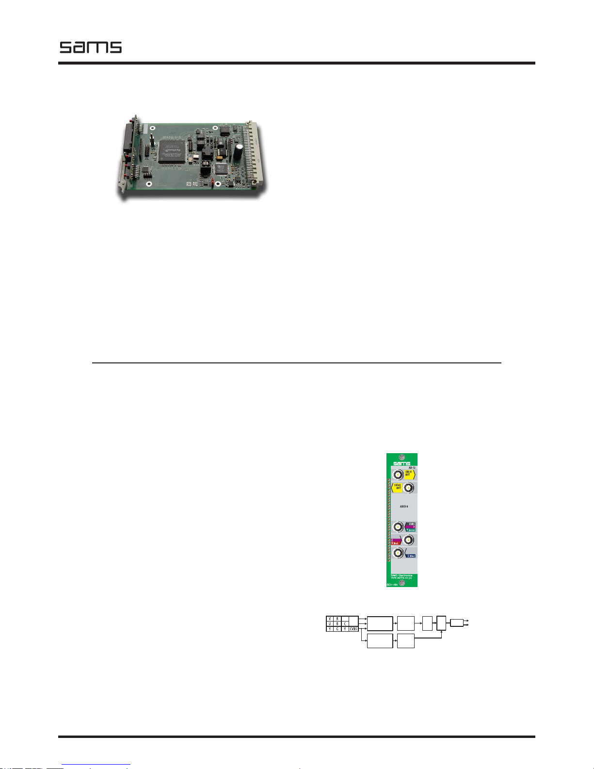
BLOCK DIAGRAM
ORDERING INFORMATION
Code Name Description
005.209 AD-12 ADC
001.509 ADCV-8 Back connector
001.605 SRU-306 Rack frame for 6 modules
BACK CONNECTOR ADCV-8
Specications and designs are subject to change without notice
AD-12
Analog to SDI converter
- Broadcast quality
- Converts YUV, RGB, CVBS or YC to digital video
- 12/10bit processing
- Fiveline adaptive 3D comb lter
- Processing delay - 1line
- Integrated Three 54MHz: Noise Shaped Video, 12-bit AD
converter and 4 x oversampling
- Integrated automatic gain control with adaptive peak white
mode
- CTI (chroma transient improvement)
- DNR (Digital Noise Reduction)
- EDH processing
- Automatic YUV pixel timing adjustment
- Input signal presence detection
- Pass or broadcast test in the case of incorrect video input
- Integrated Test Generator (Black, Color Bar)
- Easy setup with local control and LCD display
POWER
- Voltage: ........................................................... 2 x 12V AC
- Power: .........................................................................5W
TEMPERATURE
- Performance: .......................................................... 5-40°C
- Operating: .............................................................. 0-50°C
AD-12 converts composite or component analog video to SDI. With both available, composite and component (Y, Cr, Cb or RGB
or YC) inputs, this unit is ideal for converting all types of analog video. Advanced and highly exible digital output, enables highquality conversion. “12bit 4x oversampling allows the A / D conversion of high-performance 10bit output. An intelligent adjustment
system provides full digital lter frequency response, even in the composite signal. Fixed frequency 54MHz ADC and buses for all
options, allows for very precise processing and digital ltering. The module is placed in the SRU-306 3RU chassis with capacity of
6 modules. Also, the device is available in standalone version.
ANALOG
IN
SDI OUT #1
SDI OUT #2
MENU
12/10 bit
ADC
SYNC PROC GENLOCK
PIXEL CLOCK
PROC AMP
DNR
CTI
DRIVER
EDH
TRS
Page 8
ADC
elektronik
Sams elektronik d.o.o. • sams@sams.rs • www.sams.rs
8
Converters
AD CONVERTER
TECHNICAL SPECIFICATIONS
GENERAL INFORMATION
- Code: .................................................................... 005.211
- Weight: ................................................................... 1.5 Kg
- Type: .........................................................1RU rack frame
- Dimensions: ........................................ 1RU x 19” x 150mm
- Delivery includes: ............. device, power corde, user manual
ANALOG INPUT
- Number: ..................... 3, (YUV, RGB, YC, CVBS) BNC female
- Impedance: .................................................................75Ω
DIGITAL OUTPUT
- Number: .......................................................2, BNC female
- Signal type: ............................... Serial digital (SMPTE259M)
- Impedance: .................................................................75Ω
- Jitter: ..< 0.2UI (Tipical 0.1UI @ Color Bar, 10Hz lter mode)
- Level: .......................................................... 800mV ± 10%
BLOCK DIAGRAM
ORDERING INFORMATION
Code Name Description
005.211 AD-12s ADC
Specications and designs are subject to change without notice
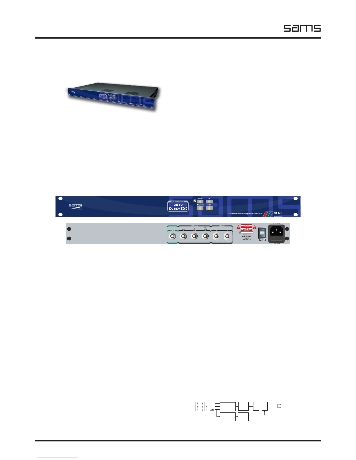
AD-12s
Analog to SDI converter
- Broadcast quality
- Converts YUV, RGB, CVBS or YC to digital video
- 12/10bit processing
- Fiveline adaptive 3D comb lter
- Processing delay - 1line
- Integrated Three 54MHz: Noise Shaped Video, 12-bit AD
converter and 4 x oversampling
- Integrated automatic gain control with adaptive peak white
mode
- CTI (chroma transient improvement)
- DNR (Digital Noise Reduction)
- EDH processing
- Automatic YUV pixel timing adjustment
- Input signal presence detection
- Pass or broadcast test in the case of incorrect video input
- Integrated Test Generator (Black, Color Bar)
- Easy setup with local control and LCD display
OUTPUT PERFORMANCE
- Bit resolution: .......................................10/12bit processing
- Black offset: ..................................................Self adjusting
- H adjustment range: ........................... 0-64μs in 37ηs steps
- V adjustment range: ......................... 0-5 lines in 1 line step
POWER
- Voltage: ................................................. ~230V AC ± 10%
- Power: ....................................................................... 30W
- Frequency: ................................................................ 50Hz
- Overload protection: .............. front Mounted Circuit Breaker
TEMPERATURE
- Performance: .......................................................... 5-40°C
- Operating: .............................................................. 0-50°C
AD-12s converts composite or component analog video to SDI. With both available, composite and component (Y, Cr, Cb or RGB
or YC) inputs, this unit is ideal for converting all types of analog video. Advanced and highly exible digital output, enables highquality conversion. “12bit 4x oversampling allows the A / D conversion of high-performance 10bit output. An intelligent adjustment
system provides full digital lter frequency response, even in the composite signal. Fixed frequency 54MHz ADC and buses for all
options, allows for very precise processing and digital ltering.
front side
rear side
ANALOG
IN
SDI OUT #1
SDI OUT #2
MENU
12/10 bit
ADC
SYNC PROC GENLOCK
PIXEL CLOCK
PROC AMP
DNR
CTI
DRIVER
EDH
TRS
Page 9

ADC
Sams elektronik d.o.o. • sams@sams.rs • www.sams.rs
elektronik
9
Converters
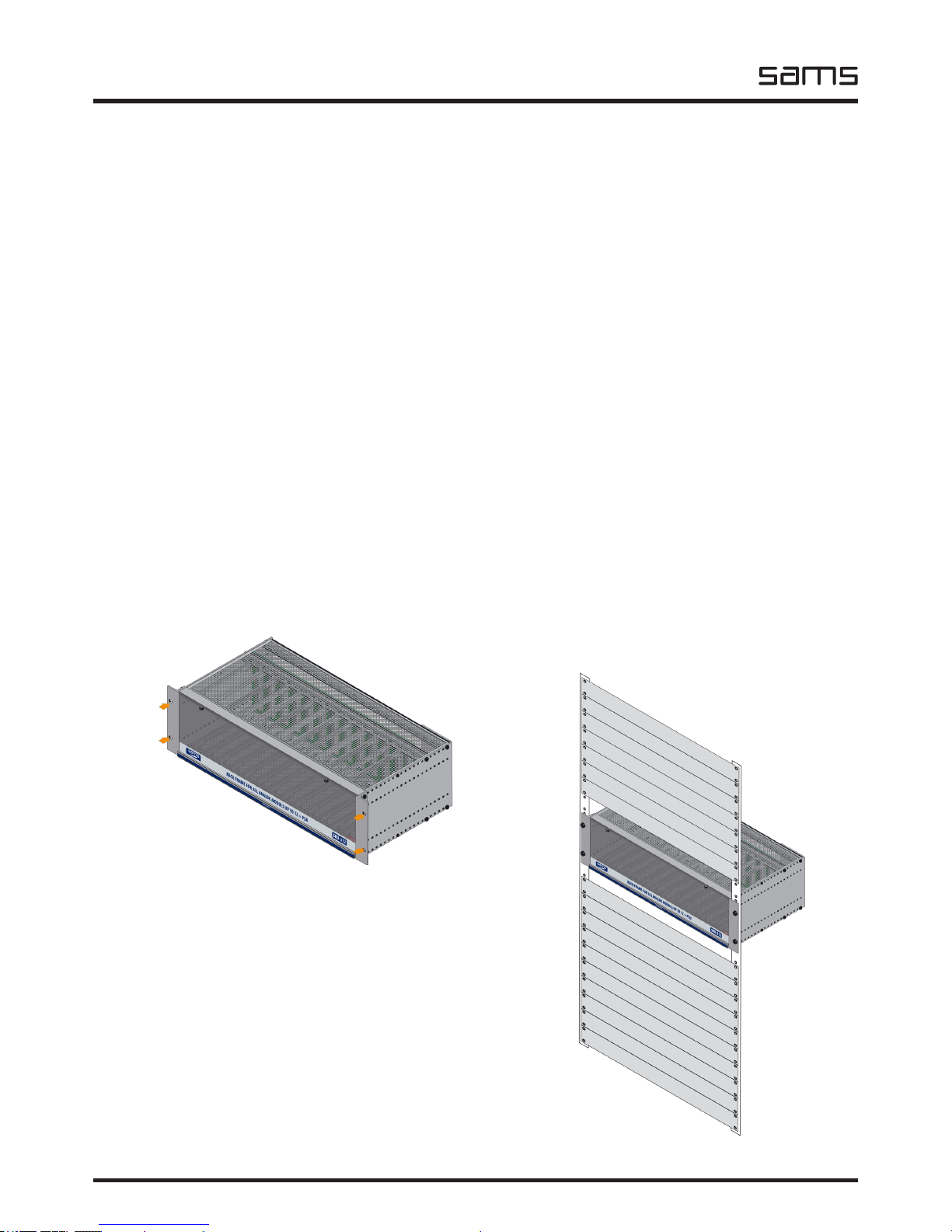
- On the front side of rack frame, unscrew the screws.
- Open the door.
MODULE INSTALATION IN SRU RACK FRAMES
Make sure that the module is set to the correct place in relation to the back connector.
BEFORE INSTALLING OR REMOVING THE MODULE FROM SRU, ALWAYS TURN OFF THE
POWER
Lock module with lever to the position.
NOTE: NEVER PLACE MODULE TO PLACE OF THE POWER SUPPLY MODULE!
The label that indicates the place for power supply module
FOR
POWER SUPPLY
ONLY
WARNING!
Page 10

ADC
elektronik
Sams elektronik d.o.o. • sams@sams.rs • www.sams.rs
10
Converters
1. The module set between the guides (not metal plate).
2. Locking lever mount behind the groove.
3. Push the lever to lock in an upright position. The module is locked.
1. 2.
3.
Page 11

ADC
Sams elektronik d.o.o. • sams@sams.rs • www.sams.rs
elektronik
11
Converters
AD-12
SDI #2
OUT
SDI #1
OUT
C
V
(Red)
AD-12
CVBS
Y
Y
(Green)
U (Blue)
ADCV-8
SDI OUTPUT #1
SDI OUTPUT #2
ANALOG IN
OPTIONS
1. CVBS
2. YC
3. YUV
4. RGB
ANALOG IN
ANALOG IN
Fix the back connector with
M2.5 screw.
Fix the back connector with
M2.5 screw.
Be sure to install a protective pad before installing the back connectors.
BACK CONNECTORS
Page 12

ADC
elektronik
Sams elektronik d.o.o. • sams@sams.rs • www.sams.rs
12
Converters
HIGH VOLTAGE!
DANGER!
Place the back connector. Fix the back connector with M2.5 screw.
1. Mass
2. Power switch
3. The socket
4. Connections for back connectors
Rear side view
SRU REAR SIDE
DO NOT INSERT SHARP METAL OBJECTS OR FINGERS INTO THE SPACE BEHIND
THE POWER PANEL!
THE SIGN “LIGHTNING IN A TRIANGLE” IS TO ALERT THE USER TO THE
PRESENCE OF LIFE-THREATENING HIGH POWER.
LABEL IS PLACED NEXT TO POWER PANEL.
Page 13

ADC
Sams elektronik d.o.o. • sams@sams.rs • www.sams.rs
elektronik
13
Converters
1
2
3
4
12/10bit analog to digital converter with frame sinchronizer
AD-12fs
www.sams.rs
MENU / BACK
OK / SAVE
DOWN
UP
ANALOG TO DIGITAL
AD12FS
Cvbs~CDI
FUSE: 500mA
AC ~230V/50Hz
POWER
www.sams.rs
Made in Serbia
AD-12fs
SN:
ANALOG INPUT
YVU
C Y
GREENREDBLUE
CVBS
SDI OUTPUT
21
EXT. REF.
USE ONLY WITH A 250V FUSE
ANALOG INPUT
YVU
C Y
GREENREDBLUE
CVBS
SDI OUTPUT
21
EXT. REF.
Connect the power cord.
The device works only on AC ~ 230 V / 50 Hz.
Rear side
Front side
Connect all necessary connectors
before the unit is turned on.
Connectors on rear side
Analog inputs
The device supports composite and component signal.
External rererence input
The device supports the black burst generator
(as Sams MSG-BB6).
SDI outputs
Turn on the device
by pressing switch.
If everything is OK, the LED will glow green.
INSTALLATION (STANDALONE)
For the best signal quality use:
- Belden 8281 or better coaxial cable for analog video
- Belden 1694A or better coaxial cable for digital video
BLOCK DIAGRAM
Page 14

ADC
elektronik
Sams elektronik d.o.o. • sams@sams.rs • www.sams.rs
14
Converters
12
3 5
4 6
AD12FS
Cvbs~SDI
AD-12fs
Warning!
Cvbs~SDI
AD-12fs
NoSignal
Cvbs~SDI
AD-12fs
ERRORS WITH CONNECTIVITY AND STATUS
No input signal
If you notice that the LED ashes
red, verify that the incoming
signal is correct or check if the
incoming signal cable is properly
connected.
THE DEVICE FUNCTIONS
1. OK/SAVE push button - enters the submenu / saving
2. STATUS LED:
GREEN - the device is in normal mode
RED ashing - has a external reference, but there is no input signal
3. Display
4. MENU/BACK push button - enter the menu from status mode / exit from the submenu
5. UP push button / Frame Freeze - choose the value in the submenu / freezes the image in the status
mode
6. DOWN push button - choose the value in the submenu
STATUS mode
When you turn on the device and if it is properly connected, the status is displayed.
Page 15

ADC
Sams elektronik d.o.o. • sams@sams.rs • www.sams.rs
elektronik
15
Converters
FACTORY SETUP
INPUT: CVBS
HV BLANK: PASS ALL
H POS: 00.000μs
V POS: 000 lines
ERROR MODE: PASS ALL
COLOUR LEVEL: 100%
Y OFFSET: 100%
Y LEVEL: 100%
CTI&DNR: OFF
ANTI ALIAS: OFF
AGC MODE: OFF
SIGNAL TYPE: STUDIO
To set the device, press the “MENU / BACK” button. Select the menu by pressing the UP / DOWN keys.
On the selected menu, press OK.
MENU
Entering the menu for setting the device
Sel.Menu
Input
AD-12fs
Page 16

ADC
elektronik
Sams elektronik d.o.o. • sams@sams.rs • www.sams.rs
16
Converters
SOURCE
CVBS
PASS ALL
YC
KILL ALL
YUV
COLOR LEVEL
Y OFFSET
Y LEVEL
CTI & DNR
ANTI ALIAS
AGC MODE
SIGNAL TYPE
1.
6.
7.
8.
9.
10.
11.
12.
YUV (BetaCam)
RGB
HV BLANK
2.
STATUS
UP
DOWN
SETTINGS
ERROR MODE
13.
5.
HORIZONTAL POSITION
3.
VERTICAL POSITION
4.
MENU/BACK
from 0%-100%-200%
from 0%-100%-200%
from 0%-100%-200%
OFF
OFF
ON
ON
OFF
STUDIO
FAST
SAT-VCR
SLOW
SAVE MEM 1-4
PASS ALL
LOAD MEM 1-4
BLACK
FACTORY!
75% COLOR BAR
KILL OUT
from 0.000μs to 63.963μs
from 1 lines to 5 lines
ADAPTIVE
Sel.Menu
Input
Sel.Menu
HV Blank
Sel.Menu
Hor.Pos
Sel.Menu
Vert.Pos
Sel.Menu
Err.Mode
Sel.Menu
ColorLvl
Sel.Menu
Y Offset
Sel.Menu
Y Level
Sel.Menu
Cti&Dnr
Sel.Menu
A.Alias
Sel.Menu
AGC Mode
Sel.Menu
Sig.Type
Sel.Menu
Setting1
AD12FS
Cvbs~SDI
MENU TREE
The bold options are the factory default settings.
Page 17

ADC
Sams elektronik d.o.o. • sams@sams.rs • www.sams.rs
elektronik
17
Converters
This menu is used to select the incoming signal.
The options are: CVBS, YC, YUV, Betacam, RGB.
The factory setting is CVBS.
Select an option by pressing the UP / DOWN keys.
1. INPUT
Once you have selected the option, press the “MENU / BACK” button. Option is temporarily saved.
Once you have selected the option, press the “MENU / BACK” button. Option is temporarily saved.
Menu - Input
Menu - HV Blank
Sel.Menu
Input
AD-12fs
Sel.Menu
HV Blank
AD-12fs
2. HORIZONTAL / VERTICAL BLANKING
This menu is used for pass / remove information that is contained in the horizontal and vertical
blanking.
Choose one of options:
- PASS ALL - allow all the information contained in the horizontal (embedded audio) and vertical blanking
(from 6 to 22 lines);
- KILL ALL - remove all information contained in the horizontal and vertical blanking.
The factory setting is PASS ALL.
Select an option by pressing the UP / DOWN keys.
Page 18

ADC
elektronik
Sams elektronik d.o.o. • sams@sams.rs • www.sams.rs
18
Converters
Once you have selected the option, press the “MENU / BACK” button. Option is temporarily saved.
Menu - Vertical position
Sel.Menu
Vert.Pos
AD-12fs
4. VERTICAL POSITION
This menu is used to adjust the vertical phase of the output video signal.
The vertical delay is adjusted in increments of one video line, from 1 up to the 5.
The factory setting is 1 lines.
Select an option by pressing the UP / DOWN keys.
Menu - Horisontal position
Sel.Menu
Hor.Pos
AD-12fs
3. HORIZONTAL POSITION
This menu is used to adjust the horizontal phase of the output video signal.
Horizontal phase shifts in the intervals 37ns (half of one pixel) up to a maximum of one video line
(63.963μs).
During the change in value, it may cause short-term image disturbance in monitor due to the transition
to a new time.
The factory setting is 0.000μs.
Select an option by pressing the UP / DOWN keys.
Once you have selected the option, press the “MENU / BACK” button. Option is temporarily saved.
Page 19

ADC
Sams elektronik d.o.o. • sams@sams.rs • www.sams.rs
elektronik
19
Converters
6. COLOR LEVEL
This menu is used to adjust the color level. This is achievable by scaling Cr and Cb signals controlled
by the user.
Control is allowed in a range of 0% to 200%.
The factory setting is 100%.
Select by pressing the UP / DOWN keys.
Once you have selected the option, press the “MENU / BACK” button. Option is temporarily saved.
Menu - Error mode
Sel.Menu
Err.Mode
AD-12fs
5. ERROR MODE
This menu is used to set how the product behaves during a fault in the signal.
Select an option:
- PASS ALL - device pass signal no matter how bad signal is;
- BLACK - the unit will generate a black image, due to poor incoming video signal;
- 75% COLOR BAR - the unit will generate a color bar, due to poor incoming video signal;
- KILL OUT - device will cancel the signal at the output due to poor incoming video signal;
The factory setting is PASS ALL.
Select an option by pressing the UP / DOWN keys.
Once you have selected the option, press the “MENU / BACK” button. Option is temporarily saved.
Menu - Color level
Sel.Menu
ColorLvl
AD-12fs
Page 20

ADC
elektronik
Sams elektronik d.o.o. • sams@sams.rs • www.sams.rs
20
Converters
Once you have selected the option, press the “MENU / BACK” button. Option is temporarily saved.
Once you have selected the option, press the “MENU / BACK” button. Option is temporarily saved.
Menu - Y offset
Menu - Y level
Sel.Menu
Y Offset
AD-12fs
Sel.Menu
Y Level
AD-12fs
7. Y OFFSET
This menu is used to adjust the brightness.
Control is allowed in a range of 0% to 200%.
The factory setting is 100%.
Select by pressing the UP / DOWN keys.
This menu is used to adjust the contrast. This is achievable by scaling Y (luma) signals controlled by
the user.
Control is allowed in a range of 0% to 200%.
The factory setting is 100%.
Select an option by pressing the UP / DOWN keys.
8. Y LEVEL
Page 21

ADC
Sams elektronik d.o.o. • sams@sams.rs • www.sams.rs
elektronik
21
Converters
Once you have selected the option, press the “MENU / BACK” button. Option is temporarily saved.
Once you have selected the option, press the “MENU / BACK” button. Option is temporarily saved.
Menu - CTI & DNR
Menu - Anti alias
Sel.Menu
Cti&Dnr
AD-12fs
Sel.Menu
A.Alias
AD-12fs
9. CTI & DNR
10. ANTI ALIAS
This menu is used to activate / deactivate the optional Digital Noise Reduction and Chroma Transient
Impovement.
Options are: ON and OFF.
The default setting is OFF.
Select by pressing the UP / DOWN keys.
In digital signal processing, this option reduces distortion known as “aliasing”. This is an ideal tool for
removing the major frequency components of the signal than it should have in the process.
Options are: ON and OFF.
The default setting is OFF.
Select by pressing the UP / DOWN keys.
Page 22

ADC
elektronik
Sams elektronik d.o.o. • sams@sams.rs • www.sams.rs
22
Converters
12. SIGNAL TYPE
This menu is used to determine the quality of input signal.
The options are: Studio and Sat-VCR.
STUDIO - used when you have a professional quality video signal, when the video signal is 75% color
bar with maximum level 1V p-p.
TV-VCR - when you use signals, which are unstable (satellite receivers, VHS, DVD, etc.), whose values
exceed 1V p-p (max. 7%).
The factory setting is STUDIO.
Select an option by pressing the UP / DOWN keys.
NOTE: When using a TV-VCR mode, then you can have irregular signals at input, which may cause the
illegal values of digital output signal.
Once you have selected the option, press the “MENU / BACK” button. Option is temporarily saved.
Menu - Signal Type
Sel.Menu
Sig.Type
AD-12fs
Once you have selected the option, press the “MENU / BACK” button. Option is temporarily saved.
Menu - AGC mode
Sel.Menu
AGC Mode
AD-12fs
11. AGC MODE
This option sets the automatic level control of signal.
The options are:
OFF - The option is disabled
FAST SLOW ADAPTIVE The default setting is OFF.
Select by pressing the UP / DOWN keys.
Page 23

ADC
Sams elektronik d.o.o. • sams@sams.rs • www.sams.rs
elektronik
23
Converters
Menu - Settings
Sel.Menu
Setting1
AD-12fs
After setup within the available menu options, it is temporarily recorded in the memory.
The number next to “Setting” means that the bank is loaded into memory.
When the device is set, select SETTING menu, press the “OK / SAVE” to open the options menu and
select one of four banks to record: SaveMem1, SaveMem2, SaveMem3 and SaveMem4. The device can
record 4 different settings.
After selecting a bank press “OK / SAVE”. The display will print “SAVED”.
If you want to stay in this menu, press the UP / DOWN keys, and to exit the MENU / BACK button.
In this menu, there are options: LoadMem1, LoadMem2, LoadMem3 and LoadMem4 or options to load
settings.
After selecting a bank press “OK / SAVE”. The display will print “LOADED”.
If you want to stay in this menu, press the UP / DOWN keys, and to exit the MENU / BACK button.
Option FACTORY! set default settings in the currently active bank.
Press the “OK / SAVE”. On display will print ‘RESETED. “
If you want to stay in this menu, press the UP / DOWN keys, and to exit the MENU / BACK button.
13. SETTINGS
Page 24

ADC
elektronik
Sams elektronik d.o.o. • sams@sams.rs • www.sams.rs
24
Converters
NOTES
 Loading...