

Page 1

HIGH DEFINITION DIGITAL TELEVISION
36” (34” Viewable) 16:9 PERFECTLY FLAT
WIDE SCREEN
34” (32” Viewable) 4:3 SUPER FLAT TUBE
29” (27” Viewable) 4:3 SUPER FLAT TUBE
USER MANUAL
Page 2

TABLE OF CONTENTS
1.FCC STATEMENT.……………………………………………............………………… 1
2.IMPORTANT SAFETY INSTRUCTION……………………………………………… 2-5
3.BACK PANEL AND CONNECTION…………..……………………………........……6-7
4.LOCATION OF BUTTONS ON REMOTE CONTROL.…………………………..……8
5.USING THE TV’S ADVANCED FEATURES........................................................9-15
6.USING THE MONITOR’S ADVANCED FEATURES.……………………….....…16-17
7.BATTERY IN REMOTE CONTROL…………..………….…………….......................18
8.FRONT PANEL AND CONNECTIONS……………………………….....………....19-21
9.ON SCREEN DISPLAY MENU SETTINGS………………………….................…22-28
10. TROUBLE SHOOTING…………….………………………….……………….…… 29-30
11.FREQUENCY TABLE……………………………………………………………..… 31-33
12.SPECIFICATIONS…………………………………………………………………… 34-3
-1-
Page 3

FCC CLASS B STATEMENT
IMPORTANT:
The equipment has been tested and found to comply with the limits for a Class B digital device, pursuant to
part 15 of FCC rules. These limits are designed to provide reasonable protection against harmful
interference in a residential installation. This equipment generates, uses and can radiate radio frequency
energy and, if not installed and used in strict accordance with the instructions, may cause harmful
interference to radio communications. However, there is no guarantee that interference will not occur in a
particular installation. If this equipment does cause harmful interference to radio or television reception,
which can be determined by turning the equipment off and on, the user is encouraged to try to correct the
interference by one or more of the following measure:
l Reorient or relocate the receiving antenna.
l Increase the separation between the equipment and the receiver.
l Connect the equipment into an outlet on a circuit different from that to which the receiver is connected.
l Consult the dealer or an experienced radio/TV technician for help.
Shielded interconnected cables and shield power cords must be employed with this equipment to insure
compliance with the pertinent RF emission limits governing this device.
Changes or modifications not expressly approved by the manufacturer could void the user’s authority to
operate the equipment and invalidate the warranty.
CANADIAN COMPLIANCE STATEMENT:
This Class B digital apparatus meets all requirements of the Canadian Interference-Causing Equipment
Regulations.
Cet appareil numérique de la Classe B respecte toutes les exigences du Règlement sur le matériel
brouilleur du Canada.
-1-
Page 4

CE (EUROPE) STATEMENT
1. Bitte lesen Sie sich diese Hinweise sorgfältig durch.
2. Heben Sie diese Anleitung für den späteren Gebrauch auf.
3. Vor jedem Reinigen ist das Gerät vom Stromnetz zu trennen. Verwenden Sie keine Flüssig- oder
Aerosolreiniger. Am besten dient ein angefeuchtetes Tuch zur Reinigung.
4. Umeine Beschädigung des Gerätes zu vermeiden sollten Sie nur Zubehörteile verwenden, die vom
Hersteller zugelassen sind.
5. Das Gerät ist vor Feuchtigkeit zu schützen.
6. Bei der Aufstellung des Gerätes ist auf sicheren Stand zu achten. Ein Kippen oder Fallen könnte
Verletzungen hervorrufen. Verwenden Sie nur sichere Standorte und beachten Sie die
Aufstellhinweise des Herstellers.
7. Die Belüftungsöffnungen dienen zur Luftzirkulation die das Gerät vor Überhitzung schützt. Sorgen Sie
dafür, daß diese Öffnungen nicht abgedeckt werden.
8. Beachten Sie beim Anschluß an das Stromnetz die Anschlußwerte.
9. Die Netzanschlußsteckdose muß aus Gründen der elektrischen Sicherheit einen Schutzleiterkontakt
haben.
10. Verlegen Sie die Netzanschlußleitung so, daß niemand darüber fallen kann. Es sollte auch nichts auf
der Leitung abgestellt werden.
11. Alle Hinweise und Warnungen die sich am Geräten befinden sind zu beachten.
12. Wird das Gerät uber einen längeren Zeitraum nicht benutzt, sollten Sie es vom Stromnetz
trennen.Somit wird im Falle einer Überspannung eine Beschädigung vermieden.
13. Durch die Lüftungsäffnungen dürfen niemals Gegenstände oder Flussigkeiten in das Gerät gelangen.
Dies könnte einen Brand bzw. elektrischen Schlag auslösen.
14. Öffnen Sie niemals das Gerät. Das Gerät darf aus Gründen der elektrischen Sicherheit nur von
authorisiertem Servicepersonal geöffnet werden.
15. Wenn folgende Situationen auftreten ist das Gerät vom Stromnetz zu trennen und von einer
qualifizierten Servicestelle zu überprufen:
l Netzkabel oder Netzstecker sind beschädigt.
l Flussigkeit ist in das Gerät eingedrungen.
l Das Gerät war Feuchtigkeit ausgesetzt.
l Wenn das Gerät nicht der Bedienungsanleitung entsprechend funktioniert oder Sie mit Hilfe
dieser Anleitung keine Verbesserung erzielen.
l Das Gerät ist gefallen und/oder das Gehäuse ist beschädigt.
l Wenn das Gerät deutliche Anzeichen eines Defektes aufweist.
16. Bei Reparaturen dürfen nur Orginalersatzteile bzw. Den Orginalteilen entsprechende Teile verwendet
werden. Der Einsatz von ungeeigneten Ersatzteilen kann eine weitere Beschädigung hervorrufen.
17. Wenden Sie sich mit allen Fragen die Service und Reparatur betreffen an Ihren Servicepartner. Somit
stellen Sie die Betriebssicherheit des Gerätes sicher.
-2-
Page 5

IMPORTANT SAFETY INSTRUCTIONS
TO REDUCE THE RISK OF ELECTRIC SHOCK, DO NOT REMOVE
CAUTION
RISK OF ELECTRIC SHOCK
DO NOT OPEN
THE TV/MONITOR’S COVER. NO USER SERVICEABLE PARTS ARE
INSIDE THE UNIT. PLEASE REFER SERVICING TO QUALIFIED
PERSONNEL.
WARNING:
1. To prevent fire or shock hazard, do not expose this monitor to rain to rain or moisture.
2. High voltage exists on the cathode-ray tube anode lead of this monitor. Before servicing, determine the
presence of high voltage by connecting the H.V. meter between the anode of CRT cap and chassis
only.
PRECAUTIONS:
1. Keep monitor away from excessive dust, high temperatures, moisture or direct sunlight.
2. Use in a well-ventilated area and do not cover ventilation openings.
3. Unauthorized modification to this equipment or usage of an unshielded connecting cable may cause
excessive interference.
4. If the picture displayed is in any way abnormal, turn off the unit and disconnect it from the electric outlet.
Verify your signal wire connections and reconnect the TV to the electric outlet.
5. Read all of these instructions and Save these instructions for later use.
6. Follow all warnings and instructions marked on the product.
7. Disconnect from the mains supply before cleaning. Do not use liquid or aerosol cleaners. Use only a
slightly damp cloth for cleaning.
8. Do not use this product near water.
9. Do not place this product on an unstable cart, stand or table. The product may fall, causing serious
damage.
10. The ventilation slots located on the back of the cabinet are for proper heat dissipation. To ensure
reliable operation of the unit and to protect it from overheating, do not block or cover the openings. Do
not place the unit on a bed, sofa, rug, or other similar surfaces. Never place the unit near or over a
radiator or heat source. Do not install unit in an enclosed area unless proper ventilation is provided.
11. The unit should be operated from the type of power source indicated on the label. If the type of
available power is unknown, consult your dealer or local power company.
-3-
Page 6

IMPORTANT SAFETY INSTRUCTIONS
12. The unit is equipped with a 3-pin grounded plug. The plug will only fit into a grounded power outlet. This
is a safety feature. If you are unable to insert the plug into the outlet, contact your electrician. Do not
alter the plug; this will defeat the safety feature.
13. Do not rest objects on the power cord.
14. Avoid placing the power cord near high traffic areas.
15. If an extension cord is used, make sure that the total ampere ratings of the products connected to the
extension cord do not exceed the extension cord ampere rating. Also make sure that the total amperes
of all products connected to the main outlet does not exceed 15 amperes.
16. Never push objects of any kind into the unit through its ventilation slots. This may result in dangerous
voltage points or electrical shorting of parts, resulting in fire or electric shock. Never spill liquid of any
kind on the unit.
17. Do not attempt to service unit yourself. Opening or removing the cover may result in exposure to
dangerous voltage points or other risks. Refer all servicing to qualified service personnel.
18. Disconnect the unit from the main supply and refer servicing to qualified service personnel under the
following conditions:
l Power cord or plug is damaged or frayed.
l Liquid has been spilled into the product.
l Unit has been exposed to water or moisture.
l Uit does not operate normally when the operating instructions are followed. Adjust only those
controls that are covered by the operating instructions, improper adjustment of other controls may
result in damage which often requires extensive work by a qualified technician to restore the unit
to normal operation.
l Unit has been dropped or the cabinet has been damaged.
l Unit exhibits a distinct change in performance, indicating a need for service.
-4-
Page 7
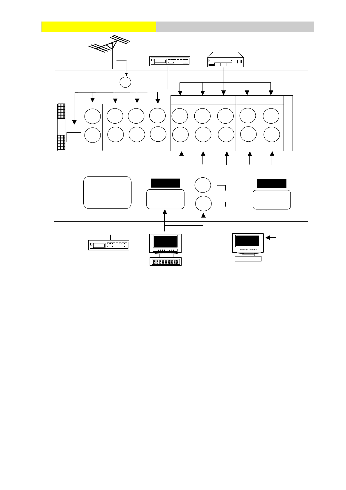
BACK PANEL CONNECTIONS
RGB IN
RGB OUT
AUDIO
R
Y
L
R L
PB PR
ˆ
AV
SET TOP BOX
ƒ
R
L
VTR/LD
DVD PLAYER
RF
µ
AV 1
…
R- AUDIO- L
VIDEO IN
CB
CR
´
AUDIO IN
COMPONENT
S-VIDEO 3
±
²
OUT
Y
R
L
L
¬
AC IN
‚
R
„
PC/NOTEBOOK
OTHER RGB
MONITOR
• AC IN: This terminal is for AC power cord.
- RGB IN: This terminal is for RGB analog signal, use with IBM PC and other compatibles.
® RGB OUT: Terminal for RGB signal output so that you can attach another display monitor to display
the same RGB analog signal that your monitor is currently displaying.
¯ RGB AUDIO IN: These terminals are for sound signal when monitor is in RGB mode.
° AV IN: Terminals are for video and stereo sound signals, used with video equipment with composite
video outputs.
± S-VIDEO 3: Terminals are for S-VIDEO and stereo sound signals, used with video equipment with
Composite video outputs.
Æ AV OUT: Terminals can output composite video and sound signals that the monitor is using. AV OUT
only supplies composite video signals. Y/PB/PR and Y/CB/CR signals are not supported.
³ Y/PB/PR: Terminal is for progressive-scan component input (Y PB PR) video signals and stereo
sound signals. This is used with progressive-scan video equipment such as progressive-scan DVD
players and high end HDTV decoders.
‰ Y/CB/CR: Terminal is for standard component video input (Y/CB/CR) video signals and stereo sound
signals.
É RF: This terminal is for connect RF antenna or cable TV box.
-5-
Page 8

BACK PANEL CONNECTIONS
NOTE:
l Before connecting any cables, refer to the safety instructions at the beginning of this manual and make
sure the unit and the video equipment are both switched off.
l Be sure to lug the AC power cord to a properly grounded outlet.
l The AV OUT terminal only supplies AV1 or AV2 composite signals and does not supply Y/PB/PR or
Y/CB/CR signals.
-6-
Page 9
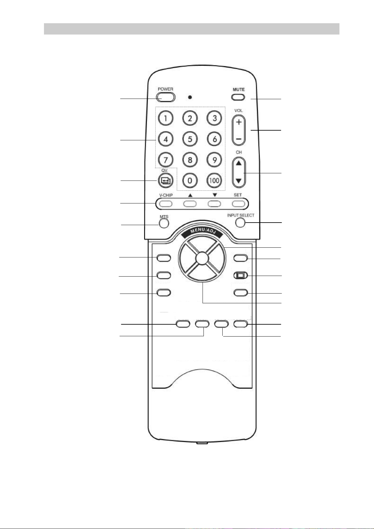
REMOTE CONTROL FUNCTIONS
5
4
WOOFER
DISPLAY
RECALL
CCD
1
7
18
5 10
12 11
2
8
16 14
13
3 20 9 21
15
6 4 17 19
DEGAUSS
3
6
AIR
CABLE
BLUEBACK
ON/OFF
FULL
SEARCH
CH
ADD/ERASE
-7-
Page 10

REMOTE CONTROL FUNCTIONS
SELECT
CH
This television features “Digital Vision”, an advanced on-screen digital display and control system to adjust
various settings within the television. These functions are accessible using the remote control for the
televison’s front control panels.
1.
POWER
Pressing the POWER button turns on the unit. When power is on, the green
POWER LED illuminates. When power is off, the unit switches to standby
mode illuminating the red STANDBY LED.
2. Press button to select the source signal to display. Each time the input button
3. Use the AIR/CABLE button to switch the tuner from receiving standard over
4. Use the FULL SEARCH button to automatically program the television to
INPUT
AIR
CABLE
FULL
SEARCH
is pressed, the on-screen display will toggle between “TV”, “AV1”, “AV2”,
S-VIDEO 3 , “Y/CB/CR”, “Y/PB/PR”, and “RGB”.
the air broadcasts or standard cable television broadcasts. If AIR is selected,
the TV can receive channels 2 to 69. If CABLE is selected, the TV can
receive channels 1 to 125.
receive broadcasts from all available channels. When this button is pushed
for 1.5 seconds, the TV will begin the FULL SEARCH process and memorize
all available channels. The search takes some time and you can cancel the
search by pressing the FULL SEARCH button during the search.
5.
Note:
l If the tuner is set to AIR (see above), the search range is from CH2 to
CH69. If the tuner is set to CABLE TV, the search range is from CH1 to
CH125.
l The searching data for AIR TV mode and CABLE TV mode is
independent. So the FULL SEARCH function must be performed twice,
once in AIR mode and once in CABLE TV mode.
Push “▲” and “▼“ to change channels. The television will automatically skip
s
t
blank channels.
-8-
Page 11

REMOTE CONTROL FUNCTIONS
QV
+
-
2
3
5 6
89
0
100
6. This button is used to add a channel to memory or erase a channel stored in
CH
ADD/ERASE
memory. With the channel that you want to add or erase selected and
displayed on the screen, press the CH ADD/ERASE button. The screen will
display “ADD” or “ERASE”. If “ADD” is displayed, it means that this channel
can be added to memory and selectable using the channel ▲▼buttons. If
“ERASE” is displayed, it means that this channel is erasable from memory
and will not be accessible using the channel ▲▼ buttons.
7. Digit Keypad Use the digit keypad to select TV channels. Push any two digits on the
keypad to select channels between CH1 and CH99. For example, to select
CH2, simply push “0” and “2”. You may also select a single-digit channel
between CH2 and CH9 by simply pressing the corresponding digit key.
When a single digit is pressed, the TV will wait for 5 seconds before changing
the channel. To select channels beyond CH100, push the “100” key first
followed by the last two digits of the channel. For example, to select CH107,
push “100”, “0”, and ”7”.
8. QV (Quick View) button allows you to instantly revert back to the previously
selected channel.
9. Use CCD to set closed caption mode. The CCD button toggles between the
CCD
following modes:
CLOSED
CAPTION
OFF
COLSED
CAPTION
1
COLSED
CAPTION
2
TEXT1
TEXT2
10. Press and hold the Volume + button to increase the volume level. Press and
VOL
hold volume - button to decrease the volume level.
The Volume +/- buttons also function as ADJ +/- buttons for the On-Screen
display functions
-9-
Page 12

REMOTE CONTROL FUNCTIONS
ard. This is normal.
11. Use MTS to toggle between SAP, MONO, or STEREO audio mode settings
12. Use MUTE button to quickly turn off the sound through the TV’s
13. Push this button to enable/disable the blue back function. The blue back
14. Use DISPLAY button to show channel information on the screen.
MTS
MUTE
BLUE BACK
ON/OFF
DISPLAY
for your television program. SAP, MONO, and STEREO audio modes are
only applicable to standard television broadcasts.
internal speakers. Once pushed, the on-screen display will indicate the
mute function is enabled. To disable the mute function, press the
button again. The on-screen display will disappear and sound will be
restored from the speakers.
function is used to suppress “snowflakes” and audible noise when the
television cannot receive a TV broadcast signal. This funtion is only
applicable to analog TV receptions.
15. The built-in woofer can add a significant bass boost to the sound of your
16. Degaussing keeps the display free from unwanted magnetism that can
WOOFER
DEGAUSS
television/monitor. Press WOOFER button to switch the built-in woofer ON or
OFF . Each time the button is pressed, the on-screen display will display
“woofer on” or “woofer off”.
result in color impurity. Each time the monitor is turned on, it is
automatically degaussed. If the unit is displayed continuously, It is
recommended that unit is degaussed at least once every few days to
remove any color impurities. Whenever the degauss button is pushed,
the display image blurs and a humming sound is he
The screen will return to normal operations in a matter of seconds. A
minimum of 20 minutes should be observed between each use of the
manual degauss button.
-10-
Page 13

REMOTE CONTROL FUNCTIONS
2
3
5 6
89
0
100
17. V-CHIP V-CHIP (Parental Guide)
This television is equipped with V-CHIP technology to prevent children from
watching unsuitable programming.
To setup V-CHIP:
1. Press V-CHIP (blue) key on remote control to enter Parental Guide
setting. Your television will display the following:
Enter
Parental code -----
2. Press the following number keys on the remote control to enter the initial
parental code: 8,4,8,4,100. After pressing the code, the screen will
display “Parental Guide ON”.to indicate the function is currently switched
on.
Parental Guide
ON/OFF
Set Page+
3. Press V-CHIP (blue) key to go into the next menu to setup parental
V-CHIP
control settings. The following menu is displayed:
Menu Code Reference
Parental Guidelines
Rating FV V S L D
TV-Y u
TV-Y7 u u
TV-G u
TV-PG u u u u u
TV-14 u u u u u
TV-MA u u u u
Set ▼ ▲ Page+
FV : Fantasy Violence
D : Sexual Dialog
L : Adult Language
S : Sexual Situations
V : Violence
TV-Y : All Children
TV-Y7 : Older Children
TV-G : General Audience
TV-PG :Guidance Suggested
TV-14 : Strongly Cautioned
TV-MA : Mature Audience
-11-
Page 14

REMOTE CONTROL FUNCTIONS
s
s
4. Use s(yellow) or t(green) keys to select the rating you want to set. The
selected rating will flash to indicate your selection. Use SET (red) key to
t
SET
5. Press V-CHIP (blue) key again to access the Motion Picture
V-CHIP
Menu Code Reference
toggle between the U (unblock) setting or B (block) setting.
Parental Guidelines
Rating FV V S L D
TV-Y U
TV-Y7 U U
TV-G U
TV-PG B B B B B
TV-14 B B B B B
TV-MA B B B B
Set ▼ ▲ Page+
Association of America (MPAA) menu. The MPAA rating menu will
display as follows:
MPAA Rating
G : General Audience
Movie Ratings
PG : Parental Guidance
G U
PG-13 : Strongly Cautioned
PG U
R : Restricted
PG-13 U
NC-17 : No One Under 17
R U
X : No One Under 17
NC-17 U
X U
Set ▼ ▲ Page+
6. Use s(yellow) or t(green) keys to select the MPAA rating you wish to set.
The selected rating will flash to indicate your selection. Use SET (red)
t
SET
key to toggle between the U (unblock) setting or B (block) setting.
MPAA Rating
Movie Ratings
G u
PG u
PG-13 u
R B
NC-17 B
X B
Set ▼ ▲ Page+
-12-
Page 15

REMOTE CONTROL FUNCTIONS
ACCOMPLISHED
2
3
5 6
89
0
100
7. After the above setting is completed, press V-CHIP (blue) key to set
V-CHIP
the parental code.
Set
Parental code *****
8. Enter a new passcode using the digit keys on the remote control.
The pass code must be 5 digits. When you’ve completed entering
the 5-digit code, press V-CHIP (blue) key to complete the process.
You can also keep the original passcode by not entering a new
pass code and pressing the V-CHIP (blue) key.
Note:
If the pass code is forgetten, use the initial pass code of 8,4,8,4,100. This is a
V-CHIP
master code that will override the system.
Parental Guide
9. When watching a channel or program that is blocked by the
V-CHIP, the following screens will display:
Blocked 13
Parental Guidelines
V-PG VS
Blocked 13
MPAA Rating
MPAA NC-17
-13-
Page 16

REMOTE CONTROL FUNCTIONS
▼
ADJ.
▲
18. For SME-34WHD5 Only
WIDE
19.
MENU
▲
20. After you have selected a category, you can increase or decrease a display
When the source of display is AV1 or AV2 or Y/CB/CR, press the WIDE
button to select the display aspect ratio. Each time the WIDE button is
pressed, the on-screen display will toggle between “4:3” and “16:9”.
To display the monitor’s on-screen display, press menu ▲▼ button. The first
line of the window displays the master picture menu and the setting of a
selected feature. The last line of the window reports the current resolution
and frequency settings.
setting. Here’s how to adjust a setting: Press the menu ▲▼ button. While the
▲
21. Press RECALL button to reset various settings to the factory’s pre-set default
RECALL
master picture menu is on screen, use the menu ▲▼ select key to choose a
category. Once you have selected a category, press the ADJ 34 button.
Each time the ADJ 4button is pressed, the settings for the category
selected will increase. Each time the ADJ 3 button is pressed, the settings
for the selected category will decrease.
value. RECALL function is not supported when the unit is using RGB or
Y/PB/PR as the input source.
-14-
Page 17

BATTERY IN REMOTE CONTROL
Open the cover on the back of the remote insert two
To avoid damage from possible battery leakage, remove
Be sure that there are no obstructions between the
The shorter the distance between the Remote control and
the monitor narrower the angle within which the Remote
▲
NOTES :
R06/AA/SUM-3 batteries.
Be sure the polarity is correct.
Replace the cover.
the batteries for extended unused periods.
Remote Control and the monitor.
Operating range is specified for normal use.
Control can operate the monitor.
-15-
Page 18

FRONT PANEL AND CONNECTIONS
INPUT
DEGAUSS
- MENU
VOL
STAND
POWER
POWER
VIDEO
VIDEO
3
ADJUST
4
AV2 IN
INPUT
DEGAUSS
- MENU
VOL +
VIDEO
VIDEO
3
ADJUST
4
AV2 IN
STAND
POWER
INPUT
POWER
¯
VIDEO
AV2 IN
Front View
36”(34” Viewable) 16:9 MONITOR
L-AUDIO-R
S-
SELECT
34” (32” Viewable) 4:3 MONITOR
L-AUDIO-R S-
SELECT
29” (27” Viewable) 4:3 MONITOR
L-AUDIO-R
S-
SELECT
- MENU +
+ -
- VOL +
+ -
STA
+
SAVING
POWER¯
BY¯
SAVING
SAVING
¯
BY
POWER¯
NOTE:
l Before connecting any cables to the AV2 IN terminals, make sure the unit and the video equipment are
both switched off.
-16-
Page 19

FRONT PANEL AND CONNECTIONS
first line of the window displays the master picture menu and the setting of
/+ buttons turns up the volume of your TV/monitor. These
remove any color impurities. Whenever the degauss button is pushed, the
screen will return to normal operations in a matter of seconds. A minimum
MENU
ADJ
1.
POWER
Pressing the POWER button turns on the unit. When power is on, the
green POWER LED illuminates. When power is off, the unit switches to
standby mode illuminating the red STANDBY LED.
2.
3. The VOLUME -
4.
DEGAUSS
To display the monitor’s on-screen display, press menu +/- button. The
a selected feature. The last line of the window reports the current
resolution and frequency settings.
buttons also function as the ADJ - / + buttons for setting TV/Monitor
settings.
Degaussing keeps the display free from unwanted magnetism that can
result in color impurity. Each time the monitor is turned on, it is
5. Press button to select the source of display. Each time the input button is
INPUT
SELECT
automatically degaussed. If the unit is displayed continuously, It is
recommended that unit is degaussed at least once every few days to
display image blurs and a humming sound is heard. This is normal. The
of 20 minutes should be observed between each use of the manual
degauss button.
pressed, the on-screen display will toggle between “AV1”, “AV2”,
S-VIDEO 3, “Y/CB/CR”, “Y/PB/PR”, and “RGB”.
AV1→AV2→S-VIDEO 3→YCBCR→YPBPR→RGB
-17-
Page 20

ON SCREEN DISPLAY MENU SETTINGS
R←→B
R←→B
The TV/Monitor function settings are set using the on-screen display. To access function settings,
simply press the MENU - / + keys on the front control panel or your remote control. Different
function settings are available for the different types of signal inputs. The following diagram
shows the different on-screen displays available for different input signals.
On-Screen Display for RGB Input
BRIGHT
M:01 FH:31KHz FV: 60Hz
BRIGHT
TV and Composite Video Inputs (AV1 and AV2)
128
128
M:TV/AV FH:15KHz FV:60Hz
BRIGHT
M:YCBCR FH:15KHz FV:60Hz
Std. Component Input (Y/CB/CR)
128
-18-
Page 21

ON SCREEN DISPLAY MENU SETTINGS
is available
Contrast is the difference in brightness between the dark and light parts
ress the ADJ + button to increase contrast. This setting is available to
Size. Press the
Size. This setting is only available to RGB
Position. This setting
R←→B
Progressive Scan Component Inputs (Y/PB/PR)
BRIGHT
M: YPBPR FH : 33KHz FV : 60Hz
COLOR
128
M: YPBPR FH :33KHz FV : 60Hz
To change the setting of a particular function, you must first highlight the function by pressing the MENU -/+
buttons while the OSD is displayed. This will toggle between the displayed functions. After selecting the
function to set, press the ADJ + or ADJ – buttons to adjust the function setting. Each time the ADJ + button
is pressed, the settings for the function will increase. Each time the ADJ – button is pressed, the setting for
the category will decrease.
The following explains the each function setting:
BRIGHTNESS: Select icon to adjust the overall picture brightness
(image black level). Set the brightness so that the dark areas of the
monitor remain black. Press the ADJ - button to decrease brightness.
Press the ADJ + button to increase brightness. This setting
to all video signal inputs.
CONTRAST: Select icon to adjust the contrast (image white level).
128
of the displayed image. Press the ADJ- button to decrease contrast.
P
all video signal inputs.
V-SIZE (Vertical Size): Select icon to adjust the vertical size of the
displayed image. Press the ADJ - button to decrease VADJ + button to increase Vand Y/PB/PR input signals.
V-CENTER (Vertical Position): Select icon to adjust the vertical
position of the displayed image. Press the ADJ- button to decrease
V-Position. Press the ADJ+ button to increase Vis only available to RGB and Y/PB/PR input signals.
-19-
Page 22

ON SCREEN DISPLAY MENU SETTINGS
Phase. This setting is
button to move the upper screen to center and to move the
screen to the outside and to move the lower screen to the center. This
s is used to compensate for earth magnetic field effect on the
button to decrease color. Press the ADJ + button to increase
o TV/AV (Composite video AV1 & AV2),
ADJ + button to increase the level of green in the image. Press the ADJ
R
H-WIDTH (Horizontal Size): Select icon to adjust the horizontal size
of the displayed image. Press the ADJ- button to decrease H-Width.
Press the ADJ + button to increase H-Width. This setting is only
available to RGB and Y/PB/PR input signals.
H-PHASE (Horizontal Position):. Select icon to adjust the horizontal
position of the displayed image. Press the ADJ- button to decrease
H-Phase. Press the ADJ + button to increase Honly available to RGB and Y/PB/PR input signals.
PINCUSHION: Select icon to adjust the amount of tapering on each
side of the displayed image. Press the ADJ- button to decrease the
amount of side pincushion. Press the ADJ + button to increase the
amount of side pincushion. This setting is only available to RGB and
Y/PB/PR input signals.
TRAPEZOID: Select icon to adjust the trapezoid.
Press ADJ lower screen to the outside. Press ADJ + button to move the upper
setting is only available to RGB and Y/PB/PR input signals.
PARALLELOGRAM: Select icon to adjust the parallelogram. Press
ADJ + button to slant the screen to left side and press ADJ - button to
slant the screen to right side. This setting is only available to RGB and
Y/PB/PR input signals.
ROTATION: Select icon to adjust the screen tilt of the displayed
image. Thi
monitor. This setting is only available to RGB and Y/PB/PR input
signals.
R-GAIN: Select icon to change the gain of red.
G-GAIN: Select t icon to change the gain of green.
B-GAIN: Select icon to change the gain of blue.
These settings are available to all video signal inputs.
BASS: Select icon to adjust bass level of sound.
TREBLE: Select icon to adjust treble level of sound.
BALANCE: Select icon to adjust the left and the right balance.
These settings are available to all video signal inputs.
COLOR: Select icon to adjust the color of the displayed image. Press
←→
the ADJ color. This setting is available t
Y/CB/CR and Y/PB/PR signal inputs.
TINT: Select icon to adjust the tint of the displayed image. Press the
- button to increase the level of red in the image. This setting is
available to TV/AV (Composite video AV1 & AV2), Y/CB/CR and
Y/PB/PR signal inputs. This function is not applicable with PAL video
signals.
SHARPNESS:Select icon to adjust the sharpness of the displayed
image.Press the ADJ - button to decrease sharpness.Press the ADJ +
button to increase sharpness.This setting is available to TV/AV
(Composite video AV1 & AV2), Y/CB/CR and Y/PB/PR signal inputs.
-20-
Page 23

POWER MANAGEMENT FUNCTION
The following is a description of the power states and the power consumed in each state:
MODE LED H-SYNC V-SYNC VIDEO POWER CONSUMPTION
on green pulse pulse active normal
power saving yellow no pulse pulse blanked <30W
power saving yellow pulse no pulse blanked <30W
power saving yellow no pulse no pulse blanked <30W
NOTE:
l The power management function requires TTL horizontal and vertical sync.
l Power saving is invalid if display is in TV, AV, Y CB CR, Y PB PR mode.
As an ENERGY STAR
®
partner, SAMPO CORPORATION has determined that this product meets the
ENERGY STAR®guidelines for energy efficiency.
-21-
Page 24

TROUBLE SHOOTING
en changed during
Turn OFF the power switch and wait 10 minutes.
The reflex wave is effected by mountain building
ause picture repeat. Try to change
Try to change the direction and highness of
Please refer to the following checklist for remedies to common problems before contacting a service representative.
Trouble condition Cause Remedy
No picture 1. Power cord disconnected.
2. Power not switched on.
3. Improperly connected signal cable.
4. Monitor in power save mode.
Color is abnormal 1. Magnetic object nearby.
2. Direction of scre
operation.
3. Improperly connected signal
cable.
Picture runs 1. Improperly connected signal cable.
2. Input signal frequency is being the
normal operating range of the
monitor.
Display image is too
dark
Display image is too
large or small
1. Brightness and contrast settings
set at minimum.
1. Horizontal size control needs
adjustment.
2. Vertical size control needs
adjustment.
Image is distorted 1. Earth’s natural magnetic field
interfering with display.
2. Picture appears
or
1. Connect power cord.
2. Turn the power switch on.
3. Connect the signal properly.
4. Press any key on computer.
1. Move the magnetic object away.
2.
Turn on the power and degauss circuit within
monitor.
3. Connect signal cable properly.
1. Connect signal cable properly.
2. Readjust your input signal to within the normal
frequency range of the monitor.
1. Adjust brightness and contrast.
1. Use the horizontal size control function setting to
adjust the image to desired size.
2. Use the vertical size control function setting to adjust
the image to desired size.
1. Use the rotation function setting to adjust the
image.
2. Use the pincushion function setting to adjust the
image.
Remote control is not
functioning
1. Weak or dead batteries.
2. Outside interference.
1. Replace batteries.
2. Turn off the TV and disconnect the AC power
cord from the fall. Wait 10 seconds and
reconnect the AC power cord. Turn on the
television again.
With sound no picture 1. Antenna direction changed?
2. Antenna a properly connected?
1. To verify the direction of antenna.
2. To verify whether the cable was connected in
properly.
With picture no sound 1. Antenna has trouble?
2. Volume adjust to min.?
3. Without connecting audio cable?
4. Non-integrate signal proanced?
1. To verify the direction of antenna.
2. To adjust the volume in properly.
3. To connect the audio cable in properly.
4. Try other channels.
No picture just blue
back
1. Antenna properly connected?
2. Non-integrate signal proanced?
1. To verify the direction of antenna.
2. Try other channels.
Picture repeat 1. The location of antenna is
appropriately?
1.
and tree to c
the direction and highness of antenna.
Appear cross line 1. Effect by other station . 1.
antenna
Picture with snowflakes
and noise.
1. Antenna has trouble ?
2. Antenna properly connected ?
1. To verify the direction of antenna.
2. To verify whether the cable was connected in
properly.
3. Antenna direction changed ?
3. To verify the direction of antenna.
-22-
Page 25

FREQUENCY TABLE
Band AIR CB CATV CH
CH
nment
VHF 02 55.25 02 2 55.25 54.00 55.25
LOW 03 61.25 03 3 61.25 60.00 61.25
04 67.25 04 4 67.25 66.00 67.25
01 4A …… 72.00 73.25
05 77.25 05 5 77.25 78.00 79.25
06 83.25 06 6 83.25 84.00 85.25
95 A-5 91.25 90.00 91.25
96 A-4 97.25 96.00 97.25
97 A-3 103.25 102.00 103.25
98 A-2 109.25 108.00 109.25
99 A-1 115.25 114.00 115.25
14 A 121.25 120.00 121.25
15 B 127.25 126.00 127.25
VHF 16 C 133.25 132.00 133.25
DISP
FP
(MHZ)
CH
DISP
CB
NO
STD BRC IRC
FP (MHZ) Assig-
BIGB 17 D 139.25 138.00 139.25
18 E 145.25 144.00 145.25
19 F 151.25 150.00 151.25
20 G 157.25 156.00 157.25
21 B 163.25 162.00 163.25
22 1 169.25 168.00 169.25
07 175.25 07 7 175.25 174.00 175.25
08 181.25 08 8 181.25 180.00 181.25
09 187.25 09 9 187.25 186.00 187.25
10 193.25 10 10 193.25 192.00 193.25
11 199.25 11 11 199.25 198.00 199.25
12 205.25 12 12 205.25 204.00 205.25
13 211.25 13 13 211.25 210.00 211.25
23 J 217.25 216.00 217.25
24 K 223.25 222.00 223.25
25 L 229.25 228.00 229.25
26 M 235.25 234.00 235.25
27 N 241.25 240.00 241.25
28 O 247.25 246.00 247.27
29 P 253.25 252.00 253.25
-24-
Page 26

FREQUENCY TABLE
Band AIR CB CATV CH
CH
nment
30 Q 259.25 258.00 259.25
31 R 265.25 264.00 265.25
32 S 271.25 270.00 271.25
33 T 277.25 276.00 277.25
34 U 283.25 282.00 283.25
35 V 289.25 288.00 289.25
36 W 295.25 292.00 295.25
37 +1 301.25 300.00 301.25
38 +2 307.25 306.00 307.25
39 +3 313.25 312.00 313.25
40 +4 319.25 318.00 319.25
41 +5 325.25 324.00 325.25
42 +6 331.25 330.00 331.25
43 +7 337.25 336.00 337.25
44 +8 343.25 342.00 343.25
45 +9 349.25 348.00 349.25
46 +10 355.25 354.00 355.25
47 +11 361.25 360.00 361.25
48 +12 367.25 366.00 367.25
49 +13 375.25 372.00 373.25
50 +14 379.25 378.00 379.25
51 +15 385.25 384.00 385.25
52 +16 391.25 390.00 391.25
53 +17 397.25 396.00 397.25
54 +18 403.25 402.00 403.25
55 +19 409.25 408.00 409.25
56 +20 415.25 414.00 415.25
57 +21 421.25 420.00 421.25
58 +22 427.25 426.00 427.25
UHF 59 V+23 433.25 432.00 433.25
60 V+24 439.25 438.00 439.25
61 V+25 445.25 444.00 445.25
62 V+26 451.25 450.00 451.25
63 V+27 457.25 456.00 457.25
64 V+28 463.25 462.00 463.25
65 V+29 469.25 468.00 469.25
14 471.25 66 V+30 475.25 474.00 475.25
15 477.25 67 V+31 481.25 480.00 481.25
16 483.25 68 V+32 487.25 486.00 487.25
17 489.25 69 V+33 493.25 492.00 493.25
18 495.25 70 V+34 499.25 498.00 499.25
19 501.25 71 V+35 505.25 504.00 505.25
20 507.25 72 V+36 511.25 510.00 511.25
21 513.25 73 V+37 517.25 516.00 517.25
DISP
FP
(MHZ)
CH
DISP
CB
NO
STD BRC IRC
FP (MHZ) Assig-
-25-
Page 27

FREQUENCY TABLE
Band AIR CH CATV CH
CH
nment
22 519.25 74 V+38 523.25 522.00 523.25
23 525.25 75 V+39 529.25 528.00 529.25
24 531.25 76 V+40 535.25 534.00 535.25
25 537.25 77 V+41 541.25 540.00 541.25
26 543.25 78 V+42 547.25 546.00 547.25
27 549.25 79 V+43 553.25 552.00 553.25
28 555.25 80 V+44 559.25 558.00 559.25
29 561.25 81 V+45 565.25 564.00 565.25
30 567.25 82 V+46 571.25 570.00 571.25
31 573.25 83 V+47 577.25 576.00 577.25
32 579.25 84 V+48 583.25 582.00 583.25
33 585.25 85 V+49 589.25 588.00 589.25
34 591.25 86 V+50 595.25 594.00 595.25
35 597.25 87 V+51 601.25 600.00 601.25
36 603.25 88 V+52 607.25 606.00 607.25
37 609.25 89 V+53 613.25 612.00 613.25
38 615.25 90 V+54 619.25 618.00 619.25
39 621.25 91 V+55 625.25 624.00 625.25
40 627.25 92 V+56 631.25 630.00 631.25
41 633.25 93 V+57 637.25 636.00 637.25
42 639.25 94 V+58 643.25 642.00 643.25
43 645.25 100 V+59 649.25 648.00 649.25
44 651.25 101 V+60 655.25 654.00 655.25
45 657.25 102 V+61 661.25 660.00 661.25
46 663.25 103 V+62 667.25 666.00 667.25
47 669.25 104 V+63 673.25 672.00 673.25
48 675.25 105 V+64 679.25 678.00 679.25
49 681.25 106 V+65 685.25 684.00 685.25
50 687.25 107 V+66 691.25 690.00 691.25
51 693.25 108 V+67 697.25 696.00 697.25
52 699.25 109 V+68 703.25 702.00 703.25
53 705.25 110 V+69 709.25 708.00 709.25
54 711.25 111 V+70 715.25 714.00 715.25
55 717.25 112 V+71 721.25 720.00 721.25
56 723.25 113 V+72 727.25 726.00 727.25
57 729.25 114 V+73 733.25 732.00 733.25
58 735.25 115 V+74 739.25 738.00 739.25
59 741.25 116 V+75 745.25 744.00 745.25
60 747.25 117 V+76 751.25 750.00 751.25
61 753.25 118 V+77 757.25 756.00 757.25
62 759.25 119 V+78 763.25 762.00 763.25
63 765.25 120 V+79 769.25 768.00 769.25
64 771.25 121 V+80 775.25 774.00 775.25
65 777.25 122 V+81 781.25 780.00 781.25
66 783.25 123 V+82 787.25 786.00 787.25
67 789.25 124 V+83 793.25 792.00 793.25
68 795.25 125 V+84 799.25 798.00 795.25
69 801.25
DISP
FP
(MHZ)
CH
DISP
CB
NO
STD BRC IRC
FP (MHZ) Assig-
-26-
Page 28

SPECIFICATIONS
MULTIMEDIA MONITOR 36” (16:9) 34” (4:3) 29” (4:3)
1. Cathode ray tube
a. tube size 36 inch
b. Dot pitch H=0.82mm H=0.8mm H=0.74mm
c. Light transmission 76% (typical) 35% typical 49% typical
2. Power
a. Input voltage 100 Vac ~ 240 Vac
b. Input current 3A at 110Vac / 60Hz
c. Power consumption 200 Watts(Max) 220 Watts(Max) 180 Watts(Max)
3. Input signal
Video signal
a. Type Analog Analog Analog
b. Polarity Positive Positive Positive
c. Amplitude RGB: 0.714 Vp-p
d. Input impedance 75 ohms 75 ohms 75 ohms
e. Dot rate 75 MHz(Max.) 75 MHz(Max.) 75 MHz(Max.)
Audio Signal
a. Type Analog Analog Analog
b. Polarity 1.0Vp-p 1.0Vp-p 1.0Vp-p
c. Amplitude ≧10KΩ ≧10KΩ ≧10KΩ
Horizontal sync
a. Type TTL TTL TTL
b. Polarity Positive or negative Positive or negative Positive or negative
c. Input impedance 1K ohm(Min) 1K ohm(Min) 1K ohm(Min)
d. Frequency RGB: 31 KHz ~ 52 KHz
Vertical sync
a. Type TTL TTL TTL
b. Polarity Positive or negative Positive or negative Positive or negative
c. Input impedance 1K ohm(Min) 1K ohm(Min) 1K ohm(Min)
d. Frequency RGB: 50 Hz ~ 120 Hz
34 inch
(16:9 Aspect Ratio)
60Hz / 50Hz
Max
Y PB PR: 1Vp-p
(with sync)
AV: 1Vp-p (with sync)
Y CB CR: 1Vp-p
(with sync)
Y PB PR: 31KHz~45KHz
AV/Y CB CR:
15.734 KHz (NTSC)
15.625 KHz (PAL)
Y PB PR: 60 Hz
AV/Y CB CR:
60 Hz (NTSC)
50 Hz (PAL)
(32 inch viewable)
100 Vac ~ 240 Vac
60Hz / 50Hz
3A at 110Vac / 60Hz
Max
RGB: 0.714 Vp-p
Y PB PR: 1Vp-p
(with sync)
AV: 1Vp-p (with sync)
Y CB CR: 1Vp-p
(with sync)
RGB: 31 KHz ~ 52 KHz
Y PB PR: 31KHz~45KHz
AV/Y CB CR:
15.734 KHz (NTSC)
15.625 KHz (PAL)
RGB: 50 Hz ~ 120 Hz
Y PB PR: 60 Hz
AV/Y CB CR:
60 Hz (NTSC)
50 Hz (PAL)
29 inch
(27 inch viewable)
100 Vac ~ 240 Vac
60Hz / 50Hz
3A at 110Vac / 60Hz
Max
RGB: 0.714 Vp-p
Y PB PR: 1Vp-p
(with sync)
AV: 1Vp-p (with sync)
Y CB CR: 1Vp-p
(with sync)
RGB: 31 KHz ~ 52 KHz
Y PB PR: 31KHz~45KHz
AV/Y CB CR:
15.734 KHz (NTSC)
15.625 KHz (PAL)
RGB: 50 Hz ~ 120 Hz
Y PB PR: 60 Hz
AV/Y CB CR:
60 Hz (NTSC)
50 Hz (PAL)
4. Connector type 15 pin D-type and RCA
JACK and S-terminal
5. Horizontal size 725 +/- 8 mm
(for RGB mode 1-9)
Vertical size 408 +/- 8 mm
(for RGB mode 1-9)
15 pin D-type and RCA
JACK and S-terminal
620 +/- 8 mm
(for RGB mode 1-9)
465 +/- 8 mm
(for RGB mode 1-9)
15 pin D-type and RCA
JACK and S-terminal
520 +/- 6 mm
(for RGB mode 1-9)
388 +/- 6 mm
(for RGB mode 1-9)
-27-
Page 29

SPECIFICATIONS
MULTIMEDIA MONITOR 36” (16:9) 34” (4:3) 29” (4:3)
6. Unit dimension:
W×H ×D (mm)
Packaging dimension :
W×H ×D (mm)
1000 × 636 × 695 866 ×718 ×583 742 × 575 ×512
1165 × 870 × 900 1030 × 870 × 760 880 × 647 ×580
7. Net weight of unit : 87 Kg 71 Kg 51 Kg
8. User Controls: Power, Brightness, Contrast, V-Size, V-Center, H-Width, H-Phase, Degauss,
Pincushion, Trapezoid, Parallelogram, Rotation, R-Gain, G-Gain, B-Gain,
Bass, Treble, Balance, Color, Tint, Sharpness, Mute, Volume, Woofer, Recall,
Input Select, WIDE.
9. Operating temperature:
0℃ to 40℃
10. Pin assignments for D-type connector
Pin 1 : RED Pin 6 : RED RETURN Pin 11 : GND
Pin 2 : GREEN Pin 7 : GREEN RETURN Pin 12 : SDA
Pin 3 : BLUE Pin 8 : BLUE RETURN Pin 13 : H-SYNC
Pin 4 : GND Pin 9 : NC Pin 14 : V-SYNC
Pin 5 : GND Pin10: GND Pin 15 : SCL
11.
a. The table below is required timings and technical description for the
36” tube (H=725mm, V=408mm standard size),
34” tube (H=620mm, V=465mm standard size),
29” tube (H=520mm, V=388mm standard size).
Mode No. 1 2 3 4 5 6 7 8 9 HDTV• HDTV‚
Resolution
&
Refresh Rate
Pixel timing +/- .5% 39.722 31.746 35.311 33.06 25 27.8 36 50 15.385 13.468 13.468 n Sec
Horizontal visible 640 640 720 640 800 800 640 800 1024 1280 1920 Dots
Horizontal total 800 832 900 864 1056 1024 832 1040 1344 1650 2200 Dots
Horizontal front porch 16 16 18 64 40 24 56 56 40 112 80 Dots
Horizontal sync 96 40 108 64 128 72 56 120 145
Horizontal back porch 48 136 54 96 88 128 80 64 105
Hor blanking time 160 192 180 224 256 224 192 240 290 260 192 Dots
Vertical visible 480 480 400 480 600 600 480 601 768 720 1080 Lines
Vertical total 525 520 449 525 628 625 509 667 806 750 1125 Lines
Vertical front porch 10 1 12 3 1 1 1 1 1 5 2 Lines
Vertical sync 2 3 2 3 4 2 3 6 6 5 5 Lines
Vertical back porch 33 36 35 39 23 22 22 23 29 20 15 Lines
Vertical blanking time 45 40 49 45 28 25 26 30 36 30 22 Lines
Horizontal frequency 31.469 37.861 31.467 35 37.879 35.156 43.27 48.09 48.363 45.1515 33.78 KHz
Vertical frequency 59.940 72.809 70.082 66.667 60.317 56.250 85 72 60 60 60 Hz
Vertical sync polarity - - + - + + - + - - - TTL
Hor sync polarity - - - + + + - + - - - TTL
Dot rate 25.2 31.2 28.3 30.204 40 35.97 36 50 65 74.25 74.25 MHz
640
480
60
640
480
72
720
400
70
640
480
66.6
800
600
60.317
800
600
56.25
640
480
85
800
600
72
1024
768
60
1280
720
60
76 76 Dots
72 36 Dots
1920
1080
60
Hz
The SYNC-ON-GREEN recall is just proper MODE 4.
b.YPBPR mode: mode 1 : 1080I (H=33KHz, V=60Hz)
mode 2 : 720p (H=45KHz, V=60Hz)
-28-
 Loading...