

Page 1

PLASMA DISPLAY
USER MANUAL
MODEL: PME-42V3
Page 2

TABLE OF CONTENTS
PAGE
1 FCC CLASS B STATEMENT………………………………………………………………………
2 Wichtige Sicherheitshinweise………………………………………………………………….….
3 IMPORTANT SAFETY INSTRUCTIONS…………………………………………………………
4 BACK PANEL CONNECTIONS…………………………………………………………………..
5 REMOTE CONTROL FUNCTIONS………………………………………………………………
6 BATTERY IN REMOTE CONTROL………………………………………………………………
7 FRONT PANEL AND CONNECTIONS……………………………………………………………
8 ON SCREEN DISPLAY MENU SETTINGS …………………………………………………….
1
2
3-4
5-6
7-9
10
11
12-14
9 POWER MANAGEMENT FUNCTION…………………………………………………………….
10 TROUBLE SHOOTING……………………………………………………………………………..
11 SPECIFICATIONS (Preliminary)………………………………………………………………….
12 INSTALLATION METHOD FOR WALL MOUNTING…………………………………………..
15
16
17-19
20-21
Page 3

FCC CLASS A STATEMENT
IMPORTANT:
The equipment has been tested and found to comply with the limits for a Class A digital device, pursuant to
part 15 of FCC rules. These limits are designed to provide reasonable protection against harmful
interference in a residential installation. This equipment generates, uses and can radiate radio frequency
energy and, if not installed and used in strict accordance with the instructions, may cause harmful
interference to radio communications. There is no guarantee that interference will not occur in a particular
installation. If this equipment does cause harmful interference to radio or television reception, which can be
determined by turning the equipment off and on, the user is encouraged to try to correct the interference by
one or more of the following measures:
•Reorient or relocate the receiving antenna.
•Increase the separation between the equipment and the receiver.
•Connect the equipment into an outlet on a circuit different from that to which the receiver is connected.
•Consult the dealer or an experienced radio/TV technician for help.
Shielded interconnected cables and shield power cords must be employed with this equipment to insure
compliance with the pertinent RF emission limits governing this device.
Changes or modifications not expressly approved by the manufacturer could void the user’s authority to
operate the equipment and invalidate the warranty.
CANADIAN COMPLIANCE STATEMENT:
This Class A digital apparatus meets all requirements of the Canadian Interference-Causing Equipment
Regulations.
Cet appareil numérique de la Classe A respecte toutes les exigences du Règlement sur le matériel
brouilleur du Canada.
Warning:
To prevent screen damage do not allow a still image to be displayed on screen for more than 1 hour. Also,
to preserve screen quality it is best to view 4:3 images in 16:9 format and to make sure that the on screen
display is not left on for extended periods of time.
-1-
Page 4

Wichtige Sicherheitshinweise
1. Bitte lesen Sie sich diese Hinweise sorgfältig durch.
2. Heben Sie diese Anleitung für den späteren Gebrauch auf.
3. Vor jedem Reinigen ist das Gerät vom Stromnetz zu trennen. Verwenden Sie keine Flüssig- oder
Aerosolreiniger. Am besten dient ein angefeuchtetes Tuch zur Reinigung.
4. Umeine Beschädigung des Gerätes zu vermeiden sollten Sie nur Zubehörteile verwenden, die vom
Hersteller zugelassen sind.
5. Das Gerät ist vor Feuchtigkeit zu schützen.
6. Bei der Aufstellung des Gerätes ist auf sicheren Stand zu achten. Ein Kippen oder Fallen könnte
Verletzungen hervorrufen. Verwenden Sie nur sichere Standorte und beachten Sie die
Aufstellhinweise des Herstellers.
7. Die Belüftungsöffnungen dienen zur Luftzirkulation die das Gerät vor Überhitzung schützt. Sorgen Sie
dafür, daß diese Öffnungen nicht abgedeckt werden.
8. Beachten Sie beim Anschluß an das Stromnetz die Anschlußwerte.
9. Die Netzanschlußsteckdose muß aus Gründen der elektrischen Sicherheit einen Schutzleiterkontakt
haben.
10. Verlegen Sie die Netzanschlußleitung so, daß niemand darüber fallen kann. Es sollte auch nichts
auf der Leitung abgestellt werden.
11. Alle Hinweise und Warnungen die sich am Geräten befinden sind zu beachten.
12. Wird das Gerät uber einen längeren Zeitraum nicht benutzt, sollten Sie es vom Stromnetz
trennen.Somit wird im Falle einer Überspannung eine Beschädigung vermieden.
13. Durch die Lüftungsäffnungen dürfen niemals Gegenstände oder Flussigkeiten in das Gerät
gelangen. Dies könnte einen Brand bzw. elektrischen Schlag auslösen.
14. Öffnen Sie niemals das Gerät. Das Gerät darf aus Gründen der elektrischen Sicherheit nur von
authorisiertem Servicepersonal geöffnet werden.
15. Wenn folgende Situationen auftreten ist das Gerät vom Stromnetz zu trennen und von einer
qualifizierten Servicestelle zu überprufen:
•Netzkabel oder Netzstecker sind beschädigt.
•Flussigkeit ist in das Gerät eingedrungen.
•Das Gerät war Feuchtigkeit ausgesetzt.
•Wenn das Gerät nicht der Bedienungsanleitung entsprechend funktioniert oder Sie mit Hilfe dieser
Anleitung keine Verbesserung erzielen.
•Das Gerät ist gefallen und/oder das Gehäuse ist beschädigt.
•Wenn das Gerät deutliche Anzeichen eines Defektes aufweist.
16. Bei Reparaturen dürfen nur Orginalersatzteile bzw. Den Orginalteilen entsprechende Teile verwendet
werden. Der Einsatz von ungeeigneten Ersatzteilen kann eine weitere Beschädigung hervorrufen.
17. Wenden Sie sich mit allen Fragen die Service und Reparatur betreffen an Ihren Servicepartner. Somit
stellen Sie die Betriebssicherheit des Gerätes sicher.
-2-
Page 5
IMPORTANT SAFETY INSTRUCTIONS
CAUTION
RISK OF ELECTRIC SHOCK
DO NOT OPEN
TO REDUCE THE RISK OF ELECTRIC SHOCK, DO NOT
REMOVE THE TV/MONITOR’S COVER. NO USER
SERVICEABLE PARTS ARE INSIDE THE UNIT. PLEASE REFER
SERVICING TO QUALIFIED PERSONNEL.
WARNING:
1. To prevent fire or shock hazard, do not expose this monitor to rain or moisture.
PRECAUTIONS:
1. Keep monitor away from excessive dust, high temperatures, moisture or direct sunlight.
2. Use in a well-ventilated area and do not cover ventilation openings.
3. Unauthorized modification this equipment or usage of an unshielded connecting cable may cause
excessive interference.
4. When the monitor is not in use, disconnect it from the electric outlet.
5. If the picture displayed is in any way abnormal, turn off the unit and disconnect it from the electric outlet.
Verify your signal wire connections and reconnect the TV to the electric outlet.
6. Read all instructions.
7. Follow all warnings and instructions marked on the product.
8. Disconnect from the electric outlet before cleaning. Do not use liquid or aerosol cleaners. Use only a
slightly damp cloth for cleaning.
9. Do not use this product near water.
10. Do not place this product on an unstable cart, stand or table. The product may fall, causing serious
damage.
11. The ventilation slots located on the back of the cabinet are for proper heat dissipation. To ensure
reliable operation of the unit and to protect it from overheating, do not block or cover the openings. Do
not place the unit on a bed, sofa, rug, or other similar surfaces. Never place the unit near or over a
radiator or heat source. Do not install unit in an enclosed area unless proper ventilation is provided.
-3-
Page 6

IMPORTANT SAFETY INSTRUCTIONS
12. The unit should be operated from the type of power source indicated on the label. If the type of
available power is unknown, consult your dealer or local power company.
13. The unit is equipped with a 3-pin grounded plug. The plug will only fit into a grounded power outlet. This
is a safety feature. If you are unable to insert the plug into the outlet, contact your electrician. Do not
alter the plug; this will defeat the safety feature.
14. Do not rest objects on the power cord.
15. Avoid placing the power cord near high traffic areas.
16. If an extension cord is used, make sure that the total ampere ratings of the products connected to the
extension cord do not exceed the extension cord ampere rating. Also make sure that the total amperes
of all products connected to the main outlet do not exceed 15 amperes.
17. Do not attempt to service unit yourself. Opening or removing the cover may result in exposure to
dangerous voltage points or other risks. Refer all servicing to qualified service personnel.
18. Disconnect the unit from the main supply and refer servicing to qualified service personnel under the
following conditions:
•Power cord or plug is damaged or frayed.
•Liquid has been spilled into the product.
•Unit has been exposed to water or moisture.
•Unit does not operate normally when the operating instructions are followed. Adjust only those controls
that are covered by the operating instructions, improper adjustment of other controls may result in
damage which often requires extensive work by a qualified technician to restore the unit to normal
operation.
•Unit has been dropped or the cabinet has been damaged.
•Unit exhibits a distinct change in performance, indicating a need for service.
-4-
Page 7
Connecting to
Connecting to video
CB
PB B Y
CR
H
Connecting to video
- ¯ ± ° ® ´ ² ³ µ 13 11 14
L
COMPONENT VIDEO INPUT
R
1 3 2 4 5 6 7 8 9
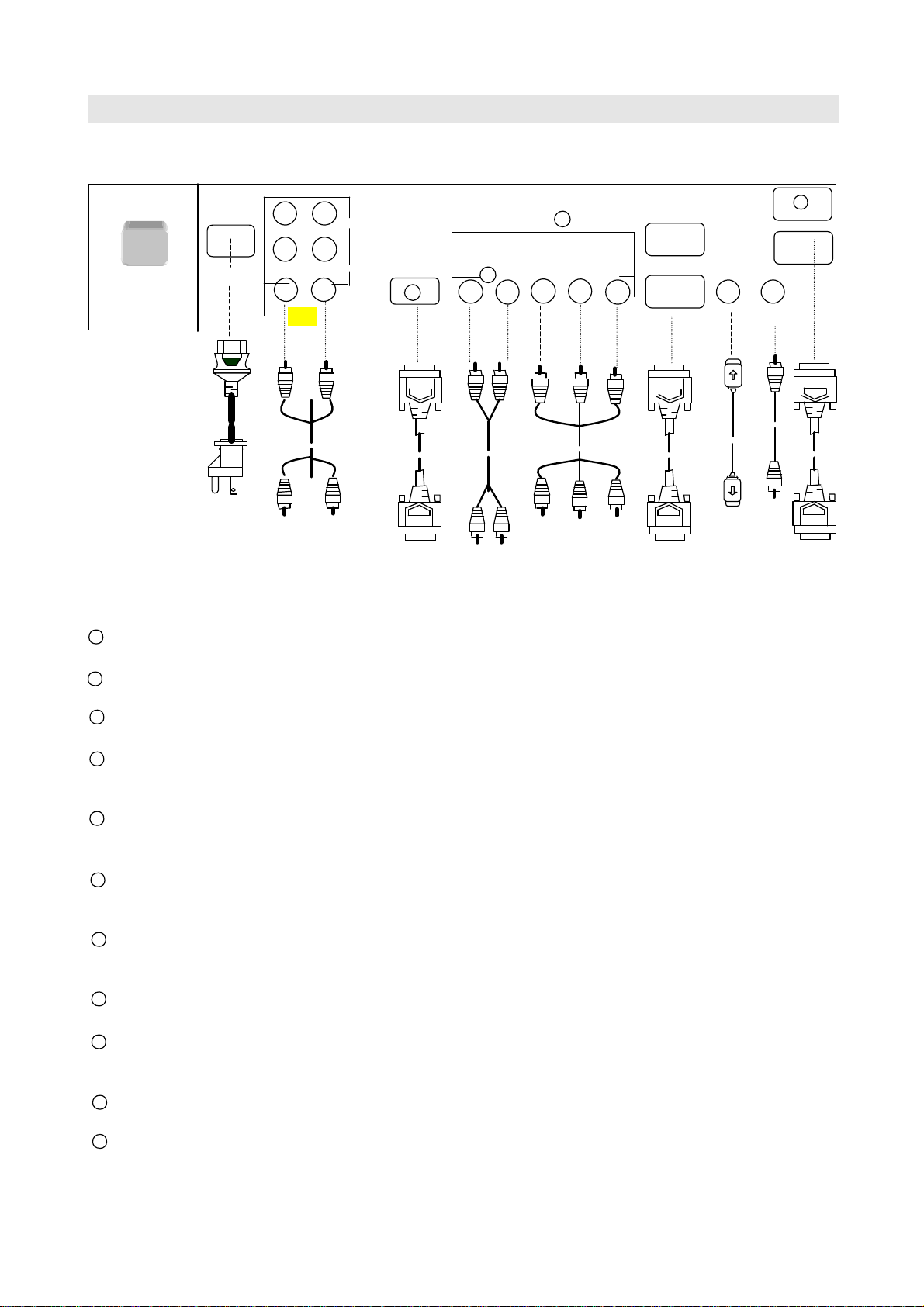
BACK PANEL CONNECTIONS
BUTTON-REAR PANEL
¬
MAIN POWER
POWER IN
AUDIO IN
OUT
RGB IN
VIDEO IN
RS 232
12
USB
Y
V
G
PR
R
RGB IN
S-VIDEO
INPUT
DVI IN
COMPOSITE
VIDEO
AC 90~260V 50/60Hz
Audio equipment
Connecting to PC
equipment
Connecting to PC
equipment
Connecting to PC
MAIN POWER: The AC main power switch.
POWER IN: This terminal is for AC power cord.
S-VIDEO: This terminal is for S-VIDEO signal cable, used with S-VIDEO equipment.
COMPOSITE IN: These terminals are for composite video signals, used with video equipment with
composite video outputs.
VIDEO AUDIO IN: Use these audio input terminals for using audio signals accompanying the video signal
when the plasma display panel is in COMPOSITE/S-VIDEO/YCBCR mode.
RGB AUDIO IN: Use these audio input terminals for using audio signals accompanying the RGB video
signal when the plasma display panel is in RGB/BNC RGB/YPBPR/DVI mode.
AUDIO OUT: These terminals output sound signals. The audio output will change according to the
mode currently displayed by the plasma display panel.
RGB IN: This terminal is for RGB analog signals for use with IBM PCs and compatibles.
RGB OUT: This terminal is for RGB signal output so that you can “daisy-chain” another RGB display
device to the same RGB analog signal currently used by the plasma display panel.
10
DVI IN: This terminal is for connecting to PC’s equipped with a digital video interface.
11
RS232 IN: This terminal is for control system signal, for use with IBM PCs and compatibles.
-5-
Page 8

BACK PANEL CONNECTIONS
12
USB: This terminal is for control system signal, for use with IBM PCs and compatibles.
13
COMPONENT VIDEO IN: This terminal is a multi-functional terminal which can receive high-definition
component video signals (YPBPR), standard component video signals
(YCBCR), and RGB analog signals.
YPBPR: Use this terminal to connect high-definition, progressive scan component video signals from
progressive scan video equipment such as progressive scan DVD players and high end HDTV
decoders.
YCBCR: Terminal is for standard component video input (YCBCR) video signals
BNC RGB: Use terminal for RGB video. Must use in conjunction with BNC H.V IN.
14
BNC H.V IN: This terminal is for RGB signal, H-sync and V-sync.
Note:
1. When using component video inputs, only one signal input can be used at any one time.
The plasma display panel will automatically detect which signal input is used.
-6-
Page 9

9 4 3
2 10 11 5 6 7 8 1
REMOTE CONTROL FUNCTIONS
-7-
Page 10

turns on the unit. When power is on, the green POWER
LED illuminates. When power is off, the unit switches to standby mode illuminating the
Use MUTE button to quickly turn off the sound through the plasma display panel’s
screen display will indicate that the mute
function is enabled. To disable the mute function, press the button again. The
ime the input button is
detect
or
REMOTE CONTROL FUNCTIONS
The plasma display panel features advanced on-screen adjustments for optimal viewing. You can access
these features by using the controls located on the plasma display panel.
1. POWER
Pressing the POWER button
red STANDBY LED.
2. - VOL +
Use the VOL -/+ buttons adjusts the volume of the plasma display panel.
3. MUTE
4. RECALL
internal speakers. Once pushed, the onon-screen display will disappear and sound will be restored from the speakers.
Press this button to set the display to the factory pre-set default value.
5. INPUT
6. DISPLAY
Press button to select the video signal source to display. Each t
pressed, the on-screen display will cycle between:
Note:
When YPBPR mode is selected, the plasma display panel will automatically
whether the input signal is standard definition component video (YCBCR)
high-definition progressive component video (YPBPR).
Press this button to turn-on or off the On-Screen Display menu.
→RGB→DVI→AV→S-VIDEO→YPBPR(YCBCR)→BNC RGB
7. AV S-VIDEO YPBPR Press these buttons to directly select the video
signal source to display.
BNC-RGB
RGB DVI
-8-
Page 11

REMOTE CONTROL FUNCTIONS
8. ON OFF
POWER
9. -MENU+
Press these buttons to directly turn the power on or power off.
To display the monitor’s on-screen display, press MENU +/- button.
10.-ADJ+
11. WIDE
Use the ADJ +/- button for setting plasma display panel settings.
This button toggles between the various Display modes available.
When the plasma display panel is in RGB, DVI, BNC RGB mode, the following choices are
available:
→16:9→ 4:3
When the plasma display panel is in AV , S-VIDEO, or YCBCR, YPBPR modes, the
following choices are available:
→16:9→ZOOM1
4:3←ZOOM2
When plasma display panel is RGB, DVI, or BNC RGB modes running at 31K/60HZ, the
following choices are available:
When PC resolution is set to 640×480 at 60Hz you can choose either 16:9 or 4:3 by
pressing the “WIDE” button on the remote.
When PC resolution is set to 852×480 at 60Hz, you can choose either w4:3 or w16:9 by
pressing the “WIDE” button on the remote.
→16:9→W 4:3→W 16:9→4:3
-9-
Page 12

BATTERY IN REMOTE CONTROL
Open the cover on the back of the remote and insert two R03/AAA/SUM-4 batteries.
Be sure the polarity is correct.
Replace the cover
NOTES:
To avoid damage from possible battery leakage, remove the
batteries for extended unused periods.
Be sure that there are no obstructions between the Remote
Control and the Monitor.
Operating range is specified for normal use.
The shorter the distance between the Remote Control and the
Monitor, the narrower the angle within which the Remote Control can operate the Monitor.
-10-
Page 13

Pressing the POWER button turns on the unit. When power is on, the green POWER
ing the
These
display. Each time the input button is
detect
or
MENU
-
FRONT PANEL AND CONNECTIONS
Front View
VOL- (ADJ -)
VOL+ (ADJ +)
POWER Button
POWER LED
INPUT
MENU +
1. POWER
2. -MENU+
3.
ADJ
- +
VOL
4. INPUT
SELECT
LED illuminates. When power is off, the unit switches to standby mode illuminat
red STANDBY LED.
To display the monitor’s on-screen display, press MENU +/- button.
Use the VOL -/+ buttons to adjust the volume of the plasma display panel.
buttons also function as the ADJ -/+ buttons for setting plasma display panel settings.
Press button to select the video signal source to
pressed, the on-screen display will cycle between:
Note:
When YPBPR mode is selected, the plasma display panel will automatically
whether the input signal is standard definition component video (YCBCR)
high-definition progressive component video (YPBPR).
→RGB→DVI→AV→S-VIDEO→YPBPR(YCBCR)→BNC RGB
-11-
Page 14

M:01 FH:31KHz FV: 60Hz
M:AV FH:15KHz FV:60Hz
BRIGHTNESS
M:
YP
FH:31KHz FV:60Hz
BRIGHTNESS
ON SCREEN DISPLAY MENU SETTINGS
The plasma display panel features advanced on-screen adjustments for optimal viewing. You can access
these features by using the MENU +/- buttons located on the plasma display panel (accessible by pressing
the center of the door) or by using the remote control. When the MENU +/- buttons are pressed, various
On-Screen Display menus are displayed depending on the input source selected.
RGB/BNC RGB/DVI On Screen Display Menu
RGB
BRIGHTNESS
AV/S-VIDEO/YCBCR On Screen Display Menu
RGB
YPBPR On Screen Display Menu
RGB
-12-
Page 15

ON SCREEN DISPLAY MENU SETTINGS
BRIGHTNESS: Select icon to adjust the overall picture brightness
(image black level). Set the brightness so that the dark areas of the
monitor remain black. Press the ADJ - button to decrease brightness.
Press the ADJ + button to increase brightness. This setting is available
to all video signal inputs
CONTRAST: Select icon to adjust the contrast (image white level).
Contrast is the difference in brightness between the dark and light parts
of the displayed image. Press the ADJ- button to decrease contrast.
Press the ADJ + button to increase contrast. This setting is available to
all video signal inputs.
V-SIZE (Vertical Size): Select icon to adjust the vertical size of the
displayed image. Press the ADJ - button to decrease V-Size. Press the
ADJ + button to increase V-Size.
V-CENTER (Vertical Position): Select icon to adjust the vertical
position of the displayed image. Press the ADJ- button to decrease
V-Position. Press the ADJ+ button to increase V-Position.
H-WIDTH (Horizontal Size): Select icon to adjust the horizontal size of
the displayed image. Press the ADJ- button to decrease H-Width. Press
the ADJ + button to increase H-Width.
H-PHASE (Horizontal Position):. Select icon to adjust the horizontal
position of the displayed image. Press the ADJ- button to decrease
H-Phase. Press the ADJ + button to increase H-Phase.
CLOCK PHASE: Select this icon to adjust the sampling clock of the
displayed image. Press the ADJ- button to decrease phase clock. Press
ADJ+ button to increase phase clock.
※ In DVI mode, clock phase is not available.
DPMS: Select this icon to change the timing of auto power off.
DPMS uses monitor power management signal to automatically reduce
monitor power consumption. While power is on, if there is no signal input
at the pre-set time, the power management function will come on
automatically, and the screen of display will automatically shut-own and
enter stand-by status.
The waiting timing of the signal can be set from 1 min. to 5 min.
The power saving function can also be switched off. (Power saver is off
in factory setting).
Please press ADJ key to move selection to next item as shown below ;
OFF 1 2 3 4 5
-13-
Page 16

ON SCREEN DISPLAY MENU SETTINGS
COLOR: Select icon to adjust the color of the displayed image. Press
the ADJ – button to decrease color. Press the ADJ + button to increase
color.
TINT: Select icon to adjust the tint of the displayed image. Press the
ADJ + button to increase the level of green in the image. Press the ADJ button to increase the level of red in the image.
※ IN YCBCR mode, TINT is not available.
SHARPNESS: Select icon to adjust the sharpness of the displayed
image. Press the ADJ - button to decrease sharpness. Press the ADJ +
button to increase sharpness.
RGB
WHITE BALANCE: Select this icon to adjust color temperature setting
between: Cool, Warm, or Hot select 1,2 or 3 as below.
1: Cool: Tend to blue tone.
2: Warm: Standard.
3: Hot : Tend to red.
-14-
Page 17

POWER MANAGEMENT FUNCTION
The following is a description of the power states and the power consumed in each state:
MODE LED H-SYNC V-SYNC VIDEO POWER CONSUMPTION
on green pulse Pulse active normal
power saving yellow no pulse Pulse blanked <5W
power saving yellow Pulse no pulse blanked <5W
power saving yellow no pulse no pulse blanked <5W
NOTE:
l The power management function requires TTL horizontal and vertical sync.
l Power saving is invalid if display is in AV, YCBCR, YPBPR mode.
As an ENERGY STAR
STAR®guidelines for energy efficiency.
®
partner, Sampo Corporation has determined that this product meets the ENERGY
-15-
Page 18

Display image is too
Display image is too
Has sound but no
VIDEO/YCBCR
ure but no
Remote control is not
TROUBLE SHOOTING
The following list represents possible anomalies you may encounter and the methods for remedying them
Please refer to this checklist prior to contacting a service representative.
Trouble condition Cause Remedy
No picture 1.Power cord disconnected?
2.Power switch on?
3.Signal cable properly connected?
4. Monitor in power save mode?
Color is abnormal 1.Signal cable properly connected? 1.Connect signal cable properly.
Picture runs 1.Signal cable properly connected?
2.Input signal outside of the required
frequency range?
Brightness and contrast at minimum? Adjust brightness and contrast.
dark
1.Horizontal control needs adjusting?
large or small
picture
Has pict
sound
functioning.
2.Vertical control needs adjusting?
1.Input source direction changed?
2. Input source properly connected?
Note:
Audio I/P has 2 sources,
One is for AV/Smode.
The other is for
YPBPR/BNC RGB/RGB/DVI mode.
1.Problem with input source?
2.Volume adjusted to min?
3.Audio cable not connected?
4.Non-integrate signal pronounced?
Note: Audio I/P has 2 sources, One
is for AV/S-VIDEO/YCBCR mode.
The other is for
YPBPR/BNC RGB/RGB/DVI mode.
1.Battery is OK?
2.Is it because of outside interference?
1.Connect power cord.
2.Turn the power switch on.
3.Connect the signal properly.
4.Press any key on your computer.
1.Connect signal cable properly.
2.Input signals, which are within the
frequency, range.
1.Adjust to desired size.
2.Adjust to desired size.
1.Verify the direction of input source.
2.Verify whether the cable was
connected properly.
1.Verify the direction of input source.
2.Adjust the volume properly.
3.Connect the audio cable properly.
4.Try other channels.
1.Change the battery.
2.Pull the AC Cord out for 10 seconds.
Then plug it in again and turn the
power on.
-16-
Page 19

SPECIFICATIONS (Preliminary)
1. Display panel
a. Screen size
b. Aspect ratio 16:9 wide
c. Number of pixels 852(Horizontal, RGB Trio ) X 480(Vertical)pixels
d. Pixel pitch 1.08mm X 1.08mm
e. Luminance 350cd/m2,at APL13%
2. Power
a. Input voltage 100 ~ 240 Vac , 50 / 60 Hz
b. Input current 3.3A
c. Inrush current 60 A p-p/20ms max
d. Power consumption
e. Stand-by & DPMS 5 watt Max (at 110Vac)
340±10% Watt ( at 110Vac/color bar pattern)
3. Connector type
4. AV/S-VIDEO signal
a. Type Analog
b. Polarity Positive
c. Amplitude
d. Frequency
e. Input impedance 75 ohm
5. YCBCR or YPBPR signal
a. Type
b. Polarity
c. Amplitude AV: 1vp-p (with sync)
d. Frequency
YCBCR
YPBPR: HDTV
15 pin dual D-SUB and RCA JACK and S-terminal
24 pin DVI connector
9 pin D-SUB
BNC for RGB or YPBPR or YCBCR
AV: 1Vp-p S-VIDEO: =1Vp-p C=0.286Vp-p
H: 15.734KHz V: 60Hz(NTSC)
H: 15.625KHz V: 50Hz(PAL)
Analog
Positive
Priorites: Y: 1Vp-p c: 0.286Vp-p
H: 15.734KHz V: 60Hz (NTSC)
H: 15.625KHz V: 50Hz (PAL)
1. 31KHz/60Hz (480P)
2. 45KHz/60Hz (720P)
3. 33KHz/60Hz(1080I)
6. BNC RGB/RGB signal
a. Type
b. Polarity
c. Amplitude RGB: 0.7Vp-p
d. Frequency
TTL
Positive or negative
H: support to 31K~91KHz
V: support to 50~85Hz
-17-
Page 20

SPECIFICATIONS (Preliminary)
7. DVI signal
a. Type
b. Polarity
c. Frequency
8. Audio signal
a. input level
b. practical max
9. Horizontal size (Standard) 920±8 mm (for mode 1∼23)
Vertical size (Standard) 518±8 mm (for mode 1∼23)
10. Dimensions Without / Stand With / Stand
Width
Height
Depth
11. Package dimensions
Width 1145 mm
Height 790 mm
Depth 370 mm
Digital
Positive or negative
H: support to 31~63KHz
V: support to 50~85Hz
Analog 500mV rms/more then 22Kohm
5W+5W max (at 10% THD max)
1050mm
661 mm
127.5mm
1050mm
719mm
275 mm
12. Weight
Net weight 79.4lbs/36 kgs
13. User controls
Brightness, Contrast, Color, Tint, Sharpness, Vertical position,
Vertical width, Horizontal position, Horizontal width, Color
temperature clock phase, DPMS.
14. Operating Temperature
Temperature 0~40℃(32~105℉)
15. Pin assignments for D-SUB connector (in / loop out)
Pin 1 : RED Pin 6 : RED GND Pin 11 : GND
Pin 2 : GREEN Pin 7 : GREEN GND Pin 12 : SDA
Pin 3 : BLUE Pin 8 : BLUE GND Pin 13 : H-SYNC
Pin 4 : GND Pin 9 : NC Pin 14 : V-SYNC
Pin 5 : GND Pin 10 : GND Pin 15 : SCL
-18-
Page 21

SPECIFICATIONS (Preliminary)
16. Pin assignments for 24 pin DVI connector
Pin 1 : TMDS Data 2- Pin 11 : TMDS Data 1/3 Shield Pin 21 : TMDS Data 5+
Pin 2 : TMDS Data 2+ Pin 12 : TMDS Data 3- Pin 22 : TMDS Clock Shield
Pin 3 : TMDS Data 2/4 Shield Pin 13 : TMDS Data 3+ Pin 23 : TMDS Clock +
Pin 4 : TMDS Data 4- Pin 14 : +5V Power Pin 24 : TMDS Clock Pin 5 : TMDS Data 4+ Pin 15 : Ground (+5, Analog
Pin 6 : DDC Clock Pin 16 : Hot Plug Detect
Pin 7 : DDC Data Pin 17 : TMDS Data 0-
Pin 8 : Analog Vertical Sync Pin 18 : TMDS Data 0+
Pin 9 : TMDS Data 1- Pin 19 : TMDS Data 0/5 Shield
Pin 10 : TMDS Data 1+ Pin 20 : TMDS Data 5-
17. RGB / DVI for VESA standard.
:
H/V Sync)
Mode No
(Hz) (K Hz) (Hz) (TTL) (TTL) (MHz)
1
2
3
4
5
6
7
8
9
10
11
12
13
14
15◎ 1280(SXGA)×1024
16◎ 1280(SXGA)×1024
19
20◎ 1280(HDTV)×720P
21◎ 1920(HDTV)×1080I
22
22
23
Resolution Refresh
640(VGA)×480
640(VGA)×480
640(VGA)×480
640(VGA)×480
800(SVGA)×600
800(SVGA)×600
800(SVGA)×600
800(SVGA)×600
800(SVGA)×600
1024(XGA)×768
1024(XGA)×768
1024(XGA)×768
1024(XGA)×768
1280(SXGA)×1024
640(VGA)×480
640(VGA)×350
720(DOS)×400
852(WGA)×480
Horizontal
Rate
60 31.5 59.94 - - 25.175
72 37.9 72.81 - - 31.500
75 37.5 75 - - 31.500
85 43.3 85.01 - - 36.000
56 35.1 56.25 + + 36.000
60 37.9 60.317 + + 40.000
72 48.1 72.19 + + 50.000
75 46.9 75 + + 49.500
85 53.7 85.06 + + 56.250
60 48.4 60.01 - - 65.000
70 56.5 70.07 - - 75.000
75 60.0 75.03 + + 78.750
85 68.7 84.99 + + 94.500
60 63.98 60.02 + + 108.00
75 79.98 75.03 + + 135.00
85 91.15 85.02 + + 157.50
50 31.5 50 - - 25.175
60 45.15 60 - - 74.250
60(I) 33.78 70 - - 74.250
70 31.50 70 - - 25.175
70 31.46 70.08 + - 28.320
60 31.72 60.41 - - 30.00
Frequency
Vertical
Frequency
Vertical
Sync
Polarity
Horizontal
Sync
Polarity
Dot rate
Attention ◎: DVI is not supported.
YPBPR for component
Mode No
1
2
3
Resolution Refresh Rate
640×480P
1920×1080I
1280×720P
60
60
60
-19-
Page 22

INSTALLATION METHOD FOR WALL MOUNTING
Set-up steps
1. Set up the roll bars marked 1,2,3,4.
2. Put the two roll bar terminals into the wall-mounting angle. Then fix them in place with M4 size screws.
They are marked 5,6,7,8.
3. Use the 3/8” driver head to fix the wall-mounting angle. The wall-mounting angle must be fixed to cement
Wall.
4. Set up the wall mounting frame and set.
a. Put the fixing screws in the gutter of the wall-mounting frame.
b. Fix the frame with 4 M5X10 size screws.
Part description
A. fix roll bar
B. fix roll bar
C. left side of wall mounting angle
D. right side of wall mounting angle
E. fixing screw
F. wall mounting frame and fixing screws M5X10 size
G. wall mounting frame and roll bar fixing screws M4X16 size
Note
1. The force for fixing M4X16 size screws should be 15Kg/cm.
2. The force for fixing M5X10 size screws should be 20Kg/cm.
3. The force for mounting screws should be 30Kg/cm.
4. The set must be mounted on a cement wall.
2 PCS
2 PCS
1 PCS
1 PCS
8 PCS
4 PCS
4 PCS
-20-
Page 23

INSTALLATION METHOD FOR WALL MOUNTING
-21-
 Loading...