

Page 1

MMM-0003
VER 1.0
34“ MULTIMEDIA MONITOR
SERVICE MANUAL
MODEL
SME-32HD5
:
:
::
Page 2
WARNING AND CAUTION
CAUTION
RISK OF ELECTRIC SHOCK
DO NOT OPEN
CAUTION: TO REDUCE THE RISK OF ELECTRIC SHOCK,
DO NOT REMOVE COVER (OR REAR)
DO USER SERVICEABLE PARTS INSIDE
REFER SERVICING TO QUALIFIED PERSONNEL
WARNING:
TO PREVENT FIRE OR SHOCK HAZARD, DO NOT EXPOSE THIS MONITOR TO
RAIN OR MOISTURE.
HIGH VOLTAGE EXISTS ON THE CATHODE-RAY TUBE ANODE LEAD OF THIS
MONITOR. BEFORE SERVICING, DETERMINE THE PRESENCE OF HIGH VOLTAGE
BY CONNECTING THE H.V. METER BETWEEN THE ANODE OF CRT CAP AND
CHASSIS ONLY.
CAUTION:
1.Keep monitor away from excessive dust, high temperature, moisture or direct
sunlight.
2.Use well ventilated area and do not cover ventilation openings.
3.Unauthorized modification to this equipment, substitution or the use of an
unshielded connecting cable may cause excessive interference.
4.When the monitor is not in use, disconnect it from the mains power supply.
®
5.As an ENERGY STAR
product meets the ENERGY STAR®guidelines for energy efficiency .
6.If the picture display is in any way abnormal, disconnect from mains. Check and
ensure the installation is correct . Then reconnect the mains supply.
Partner, SAMPO CORPORATION has determined that this
- 1 -
Page 3

IMPORTANT SAFETY INSTRUCTION
Prior to using this product, please ensure that you have carefully read and
understood all the procedures outlined in this user’s manual.
1. Read all of these instructions.
2. Save these instructions for later use.
3. Follow all warnings and instructions marked on the product.
4. Disconnect from the mains supply before cleaning. Do not use liquid or aerosol
cleaners. Use only a slightly damp cloth for cleaning.
5. Do not use this product near water.
6. Do not place this product on an unstable cart, stand or table. The product may
fall, causing serious damage.
7. Slots and openings in the cabinet located at the back and underneath are
provided for ventilation . To ensure reliable operation of the product and to
protect it from ov erheating, t hese openings must not be blocked or cov ered. The
openings should never be blocked by placing the product on a bed, sofa, rug, or
other similar surface. This product should never be placed near or over a
radiator or heat source. This product should not be placed in an enclosed
installation unless proper ventilation is provided.
8. This product should be operated from the ty pe of power source indicated on the
marketing label. If you are not sure of the type of power available, consult your
dealer or local power company.
9. This product is equipped with a 3-pin earthed plug, a plug having a
third(grounding) pin. This plug will only fit into a grounding-type power outlet.
This is a safety feature. If you are unable to insert the plug into the outlet,
contact your electrician to replace your obsolete outlet. Do not defeat the
purpose of the grounding-type plug.
10. Do not allow anything to rest on the power cord. Do not locate this product
where persons will walk on or be tripped up by the cord.
- 2 -
Page 4

IMPORTANT SAFETY INSTRUCTION
11. If an extension cord is used with this product, ensure that the total ampere
ratings of the products connected to the extension cord, do not exceed the
extension cord ampere rating. Also ensure that the total amperes of all
products connected to the mains outlet, does not exceed 15 amperes.
12. Never push objects of any kind into this product through cabinet slots as they
may touch dangerous voltage points or short out parts that could result in a
risk of fire or electric shock. Never spill liquid of any kind on the product.
13. Do not attempt to serv ice this product yourself, as opening or removing covers
may expose you to dangerous voltage points or other risks.
Refer all servicing to qualified service personnel.
14. Disconnect this product from the mains supply and refer servicing to qualified
service personnel under the following conditions:
A. When the power cord or plug is damaged or frayed.
B. If liquid has been spilled into the product.
C. If the product has been exposed to rain or water.
D. If the product does not operate normally when the operating instructions are
followed. Adjust only those controls that are covered by the operating
instructions since improper adjustment of other controls may result in
damage and will often require extensive work by a qualified technician to
restore the product to normal operation.
E. If the product has been dropped or the cabinet has been damaged.
F. If the product exhibits a distinct change in performance, indicating a need for
service.
- 3 -
Page 5

Wichtige Sicherheitshinweise
1. Bitte lesen Sie sich diese Hinweise sorgfältig durch.
2. Heben Sie diese Anleitung für den späteren Gebrauch auf.
3. Vor jedem Reinigen ist das Gerät vom Stromnetz zu trennen.
Verwenden Sie keine Flüssig- oder Aerosolreiniger.
Am besten dient ein angefeuchtetes Tuch zur Reinigung.
4. Umeine Beschädigung des Gerätes zu vermeiden sollten
Sie nur Zubehörteile verwenden, die vom Hersteller zugelassen sind.
5. Das Ger
6. Bei der Aufstellung des Ger
Ein Kippen oder Fallen könnte Verletzungen hervorrufen.
Verwenden Sie nur sichere Standorte und beachten Sie die
Aufstellhinweise des Herstellers.
7. Die Belüftungsöffnungen dienen zur Luftzirkulation die das Gerät vor
berhitzung schützt. Sorgen Sie dafür, daß diese Öffnungen nicht abgedeckt
Ü
werden.
8. Beachten Sie beim Anschluß an das Stromnetz die Anschlußwerte.
9. Die Netzanschlu
Sicherheit einen Schutzleiterkontakt haben.
10. Verlegen Sie die Netzanschlußleitung so, daß niemand darüber fallen kann.
t ist vor Feuchtigkeit zu schützen.
ä
tes ist auf sicheren Stand zu achten.
ä
steckdose muß aus Gründen der elektrischen
ß
Es sollte auch nichts auf der Leitung abgestellt werden.
11. Alle Hinweise und Warnungen die sich am Geräten befinden sind zu beachten.
12. Wird das Gerät uber einen längeren Zeitraum nicht benutzt, sollten Sie es vom
Stromnetz trennen.Somit wird im Falle einer
berspannung eine Beschädigung vermieden.
Ü
- 4 -
Page 6

Wichtige Sicherheitshinweise
13. Durch die Lüftungsäffnungen dürfen niemals Gegenstände oder
Flussigkeiten in das Gerät gelangen. Dies könnte einen Brand bzw.
elektrischen Schlag auslösen.
14. Öffnen Sie niemals das Gerät. Das Gerät darf aus Gründen der elektrischen
Sicherheit nur von authorisiertem Servicepersonal geöffnet werden.
15. Wenn folgende Situationen auftreten ist das Gerät vom Stromnetz zu trennen
und von einer qualifizierten Servicestelle zu überprufen:
a - Netzkabel oder Netzstecker sind beschädigt.
b - Flussigkeit ist in das Ger
c - Das Gerät war Feuchtigkeit ausgesetzt.
d - Wenn das Ger
oder Sie mit Hilfe dieser Anleitung keine Verbesserung erzielen.
e - Das Gerät ist gefallen und/oder das Gehäuse ist beschädigt.
f - Wenn das Gerät deutliche Anzeichen eines Defektes aufweist.
16. Bei Reparaturen dürfen nur Orginalersatzteile bzw. Den Orginalteilen
entsprechende Teile verwendet werden. Der Einsatz von ungeeigneten
Ersatzteilen kann eine weitere Beschädigung hervorrufen.
17. Wenden Sie sich mit allen Fragen die Service und Reparatur betreffen an Ihren
Servicepartner. Somit stellen Sie die Betriebssicherheit des Gerätes sicher.
t nicht der Bedienungsanleitung entsprechend funktioniert
ä
t eingedrungen.
ä
- 5 -
Page 7

FCC CLASS-B STATEMENT
IMPORTANT:
The equipment has been tested and found to comply with the limits for a Class B
digital device, pursuant to part 15 of FCC rules. These limits are designed to
provide reasonable protection against harmful interference in a residential
installation. This equipment generates, uses and can radiate radio frequency
energy and, if not installed and used in strict accordance with the instructions,
may cause harmful interference to radio communications. However, there is no
guarantee that interference will not occur in a particular installation. If this
equipment does cause harmful interference to radio or t elevision reception, which
can be determined by turning the equipment off and on, the user is encouraged to
try to correct the interference by one or more of the following measure:
- Reorient or relocate the receiving antenna.
- Increase the separation between the equipment and the receiver.
- Connect the equipment into an outlet on a circuit different from that to which the
receiver is connected.
- Consult the dealer or an experienced radio/TV technician for help.
Shielded interconnected cables and shield power cords must be employed with
this equipment to insure compliance with the pertinent RF emission limits
governing this device.
Changes or modifications not expressly approved by the manufacturer could void
the user’s authority to operate the equipment and invalidate the warranty.
NOTICE OF COMPLIANCE WITH CANADIAN INTERFERENCE-CAUSING
EQUIPMENT REGULATIONS
This Class B digital apparatus meets all requirements of the Canadian
Interference-Causing Equipment Regulations.
Cet appareil numérique de la Classe B respecte toutes les exigences du Règlement sur
le matériel brouilleur du Canada.
- 6 -
Page 8

SPECIFICATIONS:
MULTIMEDIA MONITOR 36” (16:9) 34” (4:3) 29” (4:3)
1. Cathode ray tube
a. tube size 36 inch
b. Dot pitch H=0.82mm H=0.8mm H=0.74mm, V=0.64mm
c. Light transmission 76% (center) 35% typical 49% typical
2. Power
a. Input voltage 100 Vac ~ 240 Vac
b. Input current 3A at 110Vac / 60Hz
c. Power consumption 200 Watts(Max) 220 Watts(Max) 180 Watts(Max)
3. Input signal
Video signal
a. Type Analog Analog Analog
b. Polarity Positive Positive Positive
c. Amplitude
d. Input impedance 75 ohms 75 ohms 75 ohms
e. Dot rate 75 MHz(Max.) 75 MHz(Max.) 75 MHz(Max.)
Audio Signal
a. Type Analog Analog Analog
b. Polarity 1.0Vp-p 1.0Vp-p 1.0Vp-p
c. Amplitude
Horizontal sync
a. Type TTL TTL TTL
b. Polarity Positive or negative Positive or negative Positive or negative
c. Input impedance 1K ohm(Min) 1K ohm(Min) 1K ohm(Min)
d. Frequency
Vertical sync
a. Type TTL TTL TTL
b. Polarity Positive or negative Positive or negative Positive or negative
c. Input impedance 1K ohm(Min) 1K ohm(Min) 1K ohm(Min)
d. Frequency
34 inch
(16:9 Aspect Ratio)
60Hz / 50Hz
Max
RGB: 0.714 Vp-p
Y PB PR: 1Vp-p
(with sync)
AV: 1Vp-p (with sync)
Y CB CR: 1Vp-p
(with sync)
10K
≧≧≧≧
RGB: 31 KHz ~ 52 KHz
Y PB PR: 31KHz~45KHz
AV/Y CB CR:
RGB: 50 Hz ~ 120 Hz
Y PB PR: 60 Hz
AV/Y CB CR:
ΩΩΩΩ
15.734 KHz (NTSC)
15.625 KHz (PAL)
60 Hz (NTSC)
50 Hz (PAL)
(32 inch viewable)
100 Vac ~ 240 Vac
60Hz / 50Hz
3A at 110Vac / 60Hz
Max
RGB: 0.714 Vp-p
Y PB PR: 1Vp-p
(with sync)
AV: 1Vp-p (with sync)
Y CB CR: 1Vp-p
(with sync)
10K
≧≧≧≧
RGB: 31 KHz ~ 52 KHz
Y PB PR: 31KHz~45KHz
AV/Y CB CR:
RGB: 50 Hz ~ 120 Hz
Y PB PR: 60 Hz
AV/Y CB CR:
ΩΩΩΩ
15.734 KHz (NTSC)
15.625 KHz (PAL)
60 Hz (NTSC)
50 Hz (PAL)
29 inch
(27 inch viewable)
100 Vac ~ 240 Vac
60Hz / 50Hz
3A at 110Vac / 60Hz
Max
RGB: 0.714 Vp-p
Y PB PR: 1Vp-p
(with sync)
AV: 1Vp-p (with sync)
Y CB CR: 1Vp-p
(with sync)
10K
≧≧≧≧
RGB: 31 KHz ~ 52 KHz
Y PB PR: 31KHz~45KHz
AV/Y CB CR:
RGB: 50 Hz ~ 120 Hz
Y PB PR: 60 Hz
AV/Y CB CR:
ΩΩΩΩ
15.734 KHz (NTSC)
15.625 KHz (PAL)
60 Hz (NTSC)
50 Hz (PAL)
4. Connector type 15 pin D-type and RCA
JACK and S-terminal
5. Horizontal size 725 +/- 8 mm
(for RGB mode 1-9)
Vertical size 408 +/- 8 mm
(for RGB mode 1-9)
- 7 -
15 pin D-type and RCA
JACK and S-terminal
620 +/- 8 mm
(for RGB mode 1-9)
465 +/- 8 mm
(for RGB mode 1-9)
15 pin D-type and RCA
JACK and S-terminal
520 +/- 6 mm
(for RGB mode 1-9)
388 +/- 6 mm
(for RGB mode 1-9)
Page 9
SPECIFICATIONS:
MULTIMEDIA MONITOR 36” (16:9) 34” (4:3) 29” (4:3)
6. Unit dimension:
W
××××H ××××
D (mm)
Packaging dimension :
W
××××H ××××
D (mm)
1000
1165
××××
××××
636
870
695 866
××××
900 1030
××××
××××
××××
718
583 742
××××
870
760 880
××××
××××
××××
575
647
××××
××××
512
580
7. Net weight of unit : 87 Kg 71 Kg 51 Kg
8. User Controls: Power, Brightness, Contrast, V-Size, V-Center, H-Width, H-Phase,
Degauss, Pincushion, Trapezoid, Parallelogram, Rotation, R-Gain,
G-Gain, B-Gain, Bass, Treble, Balance, Color, Tint, Sharpness, Mute,
Volume, Woofer, Recall, Input Select, WIDE.
9. Operating temperature:
0
℃℃℃℃
to 40
℃℃℃℃
10. Pin assignments for D-type connector
Pin 1 : RED Pin 6 : RED RETURN Pin 11 : GND
Pin 2 : GREEN Pin 7 : GREEN RETURN Pin 12 : SDA
Pin 3 : BLUE Pin 8 : BLUE RETURN Pin 13 : H-SYNC
Pin 4 : GND Pin 9 : NC Pin 14 : V-SYNC
Pin 5 : GND Pin10: GND Pin 15 : SCL
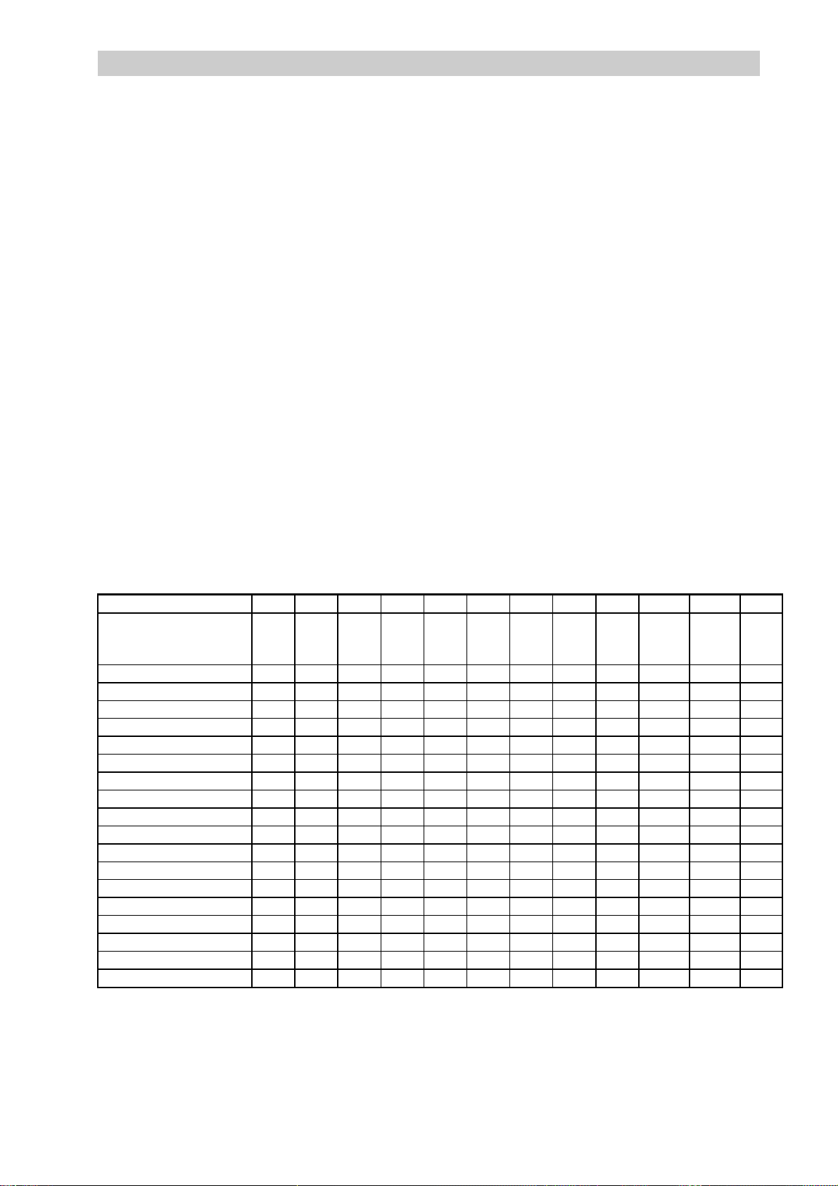
11.
a. The table below is required timings and technical description for the
36” tube (H=725mm, V=408mm standard size),
34” tube (H=620mm, V=465mm standard size),
29” tube (H=520mm, V=388mm standard size).
Mode No.
Resolution
&
Refresh Rate
Pixel timing +/- .5%
Horizontal visible
Horizontal total
Horizontal front porch
Horizontal sync
Horizontal back porch
Hor blanking time
Vertical visible
Vertical total
Vertical front porch
Vertical sync
Vertical back porch
Vertical blanking time
Horizontal frequency
Vertical frequency
Vertical sync polarity
Hor sync polarity
Dot rate
1 2 3 4 5 6 7 8 9 HDTV
70
640
480
66.6
60.317
640
640
480
480
60
39.722 31.746 35.311 33.06 25 27.8 36 50 15.385 13.468 13.468 n Sec
640 640 720 640 800 800 640 800 1024 1280 1920 Dots
800 832 900 864 1056 1024 832 1040 1344 1650 2200 Dots
16 16 18 64 40 24 56 56 40 112 80 Dots
96 40 108 64 128 72 56 120 145 76 76 Dots
48 136 54 96 88 128 80 64 105 72 36 Dots
160 192 180 224 256 224 192 240 290 260 192 Dots
480 480 400 480 600 600 480 601 768 720 1080 Lines
525 520 449 525 628 625 509 667 806 750 1125 Lines
10 1 12 3 1 1 1 1 1 5 2 Lines
2 3 2 3 4 2 3 6 6 5 5 Lines
33 36 35 39 23 22 22 23 29 20 15 Lines
45 40 49 45 28 25 26 30 36 30 22 Lines
31.469 37.861 31.467 35 37.879 35.156 43.27 48.09 48.363 45.1515 33.78 KHz
59.940 72.809 70.082 66.667 60.317 56.250 85 72 60 60 60 Hz
- - + - + + - + - - - TTL
- - - + + + - + - - - TTL
25.2 31.2 28.3 30.204 40 35.97 36 50 65 74.25 74.25 MHz
720
400
72
The SYNC-ON-GREEN recall is just proper MODE 4.
b. YPBPR mode: mode 1 : 1080I (H=33KHz, V=60Hz)
mode 2 : 720p (H=45KHz, V=60Hz)
800
600
800
600
56.25
640
480
85
800
600
72
1024
768
60
1280
720
60
HDTV
cccc
1920
1080
60
dddd
Hz
- 8 -
Page 10

CONNECTING YOUR MONITOR
A
V
⑤
AV 1
R- AUDIO- L
VIDEO IN
Y
CB
CR
⑧
AUDIO IN
R
COMPONENT
L
⑥
OUT
R
L
Y
⑦
PB
PR
R
L
②
L
R
AUDIO
RGB OUT
④
RGB IN
①
AC IN
③
1. AC IN:
This terminal is for AC power cord.
2. RGB IN:
This terminal is for RGB analog signal, use with IBM PC and other compatibles.
3. RGB OUT:
This terminal can output RGB analog signal that your monitor is using.
(* This terminal is for rear RGB in Signals )
4. RGB AUDIO IN:
These terminals are for sound signal when monitor is in RGB mode.
5. AV IN:
These terminals are for video and stereo sound signals, used with video equipment.
6. AV OUT:
These terminals can output video and sound signals that your monitor is using.
7. Y PB PR:
This terminal is for Y PB PR signal and stereo sound signals, used with Y PB PR equipment.
8. Y CB CR:
NOTE :
1. Please follow the above description when connecting your display.
This terminal is for Y CB CR signal and stereo sound signals, used with Y CB CR equipment.
2. This terminal (AV OUT) only supply the AV1 or AV2 type signal not suppl y the Y PB PR
and Y CB CR type signal.
- 9 -
Page 11

LOCATION OF BUTTONS ON REMOTE CONTROL
POWER button (page 13)
MUTE button (page 13)
WIDE button (page 23)
DEGAUSS button (page 14)
DEGAUSS
VOLUME +/- button (page 13)
INPUT SELECT button (page 23)
MENU button (page 14)
CCD
ADJUST button (page 16)
RECALL button (page 13)
WOOFER DISPLAY
WOOFER button (page 13)
The used condition of R/C ’s key
For monitor used
For tuner card used
POWER、MUTE、DEGAUSS、MENU+、MENU-、INPUT SELECT
ADJ+、ADJ-、VOLUME+、VOLUME-、WOOFER、RECALL、WIDE
MTS,CHANNEL+,CHANNEL-,CH ADD/ERASE,FULL SEARCH,CCD,BLUE
AIR
BLUE BACK
ON/OFF
FULL
SEARCH
CH
ADD/ERASE
(OPTIONAL)
BACK ON/OFF,AIR/CABLE,DISPLAY,0~9, 100,QV,SET, ▼, ▲, V-CHIP
NOTE: This remote control can be used for monitor and tuner card (OPTIONAL).
- 10 -
Page 12

LOCATION OF CONTROL (ON FRONT PANEL)
Front view
L-AUDIO-R
AV2 IN
VIDEO
S-VIDEO
INPUT
SELECT
(page 23) (page 14) (page 13/16) (page 13)
INPUT
SELECT
DEGAUSS
----
MENU
DEGAUSS
++++
-
MENU +
----
VOL
ADJUST
ADJUST
-
++++
VOL +
STAND
↓↓↓↓
BY
POWER
SAVING
POWER
POWER
POWER
SAVING
STAND
BY
NOTE:
1. AV2 IN: These terminals are for video and stereo sound signals, used with video equipment .
2. This terminal (select AV2 mode) is for S-VIDEO signal cable, used with S-VIDEO equipment.
- 11 -
Page 13

INSTALLATION
A
1. Before you connect any cables, refer to the safety instructions at the beginning of this manual and make
sure your computer (or video equipment) and display are switched off.
2. Connect the video cable (AV, S-Video or RGB cable) and audio cable to your monitor.
3. Connect the AC power cord to your monitor.
4. Plug the AC power cord to a properly grounded outlet.
5. Turn on your computer or video equipment.
6. Turn on your monitor‘s power by pushing the power button. The power indicator should be illuminated.
NOTE: If the button does not function due to interference, disconnect from the
mains for 10 seconds. Then reconnect and turn the power on.
VIDEO IN
CB
CR
AUDIO IN
R
COMPONENT
L
AV 1
R- AUDIO- L
Y
LASER DISK or
VCD or VTR
V
AC IN
OUT
R
L
RGB IN
Y
GAME PLAYER DVD PLAYER / SET TOP BOX
PB
PR
L
R
AUDIO
PC/NOTEBOOK
R
L
RGB OUT
MONITOR
L-AUDIO-R
AV2 IN
VIDEO
S-VIDEO
INPUT
SELECT
DEGAUSS
-
MENU +
ADJUST
-
VOL +
POWER
POWER
SAVING
STAND
BY
- 12 -
Page 14

USING THE MONITOR’S ADVANCED FEATURES
The ” Digital vision” feature advanced on screen adjustment for optimal viewing. To access the
advanced features, open the access panel by pressing the center of the door on the set or use the
remote control.
POWER
- VOLUME +
MUTE
R/C ONLY
Press the power button, when the green LED (power) lights up, the
power is ON. Press the button again, the green LED
Disappears and the red LED (stand by) lights up indicating that the
power is OFF.
The following audio functions are available only if speakers are
Attached.
Press and hold the Volume + button to increase the vo lume level.
Press and hold volume - button to decrease the volume level.
The Volume +/- button on front panel become ADJ +/- button, after
the menu window appears on screen.
Use this button to quickly turn off the sound being heard through
the speakers. To enable the mute functions simply press the
button. (Once pushed, the on screen display will appear next to the
button indicating that the mute function is enabled). To disable the
RECALL
R/C ONLY
WOOFER
R/C ONLY
mute function, simply press the button again, the On Screen
Display will disappear and sound will be restored from the
speakers.
Press this button to return the display to the factory pre-set
Default value. No recall item:
RGB : Rotation
Y PB PR: Rotation
Press this button to switch the woofer ON or OFF.
Each time the button is pressed, the on screen display will appear
“woofer on”, “woofer off” in turn.
- 13 -
Page 15

USING THE MONITOR’S ADVANCED FEATURES
DEGAUSS
Each time you turn on your monitor it is aut omatically Degaussed .
Degaussing keeps the display free from unw anted magnetism that
can result in color impurity. If you leave your display on
continuously, we recommend that you degauss it at least every few
days to remove any color impurities.
Press the degauss button, then degaussing is accompanied by
brief instability of the displayed image and a brief humming Sound.
A minimum of 20 minutes should be observed between
Each use of the manual degausses button.
MENU - MENU +
The On Screen Display menus of RGB mode and TV/AV mode, Y CB CR, Y PB PR mode appear below.
To view the monitor current settings press menu +/- button
And an On Screen Display window appears. The last line of the
window reports the current resolution and frequency settings. The
first line of the window displays the master picture menu and the
setting of a selected feature.
RGB menu On Screen Display
BRIGHT
M:01 FH:31KHz FV: 60Hz
128
TV/AV menu On Screen Display
R
R←→
←→BBBB
R R
BRIGHT
M:TV/AV FH:15KHz FV:60Hz
←→←→
128
- 14 -
Page 16

USING THE MONITOR’S ADVANCED FEATURES
Y CB CR menu on screen display:
R
R←→
←→BBBB
R R
←→←→
BRIGHT
M: YCBCR FH :15KHz FV :60Hz
128
Y PB PR menu on screen display
(Menu 1)
BRIGHT
128
M: YPBPR FH : 33KHz FV : 60Hz
(Menu 2)
R
R←→
←→BBBB
R R
←→←→
COLOR
M: YPBPR FH :33KHz FV : 60Hz
128
To change monitor setting of the Master Picture Menu, you must
choose a category, and then adjust the value of each category.
Here’s how to select a category:
Press the menu + or menu – button while the master picture menu
is on screen.
Each time the menu + button is pressed, a menu icon show s red
for selection. Beginning with the starting position, and moving to
the right, pressing the menu + button continuously will circulate
the selector, eventually returning to the starting position.
Press the menu – button and it will select menu icon in the
opposite direction, eventually returning to the starting position.
- 15 -
Page 17

USING THE MONITOR’S ADVANCED FEATURES
ADJ
- VOL +
After you have selected a category, you can increase or decrease
a display setting. Here’s how to adjust a setting:
Press the menu +/- button. While t he master picture menu is on
screen, use the menu + or menu – select key to choose a
category. Once you have selected a category, press the ADJ + or
ADJ – button. Each time the ADJ + adjust button is pressed, the
settings for the category selected will increase. Each time the
ADJ – button is pressed, the settings for the category selected
will decrease.
You can adjust monitor settings for the following categories:
RGB menu On Screen Display
BRIGHT
128
M : 01 FH:31KHz FV: 60Hz
BRIGHT.
(image black level). Set the brigh tness so that the d ark areas of
the monitor remain black. Press the ADJ - button to decrease
brightness. Press the ADJ + button to increase brightness.
CONTRAST
white level). Contrast is the difference in brightness between the
Dark and light parts of the displayed image. Press the ADJ-
Button to decrease contrast. Press th e ADJ + button to increase
contrast.
V-SIZE
displayed image. Press the ADJ - button to decrease V-Size.
Press the ADJ + button to increase V-Size.
Select this icon to adjust the overall picture brightness
. Select this icon to adjust the contrast (image
. Select this icon to adjust the vertical size of the
V-CENTER
the displayed image. Press the ADJ- button to decrease
V-Position. Press the ADJ+ button to increase V-Position.
. Select this icon to adjust the vertical position of
- 16 -
Page 18

USING THE MONITOR’S ADVANCED FEATURES
H-WIDTH
displayed image. Press the ADJ- button to decrease H-Width.
Press the ADJ + button to increase H-Width.
. Select this icon to adjust t he horizontal size of the
H-PHASE
the displayed image. Press the ADJ- button to decrease H-Phase.
Press the ADJ + button to increase H-Phase.
. Select this icon to adjust the horizontal position of
PINCUSHION
on each side of the displayed image. Press the ADJ- button to
decrease the amount of side pincushion. Press the ADJ + button
to increase the amount of side pincushion.
TRAPEZOID
Press ADJ - button to let the upper screen move to center and
lower screen move to outside. Press ADJ + button to let the upper
screen move to outside and lower screen move to center.
. Select this icon to adjust the amount of
. Select this icon to adjust the trapezoid.
tapering
PARALLELOGRAM
parallelogram. Press ADJ + button to let the screen slant to left
side and press ADJ - button to let the screen slant to right side.
ROTATION.
displayed image. This is used to compensate for earth magnet ic
field effect on the monitor.
Select this icon to adjust the screen tilt of the
R-GAIN.
G-GAIN.
B-GAIN.
BASS.
Select this icon to change the gain of red.
Select this icon to change the gain of green
Select this icon to change the gain of blue.
Select this icon to adjust bass of sound.
. Select this icon to adjust the
.
TREBLE.
BALANCE.
Select this icon to adjust treble of sound.
Select this icon to adjust balance of sound.
- 17 -
Page 19

USING THE MONITOR’S ADVANCED FEATURES
TV/AV menu on screen display
R
R←→
←→BBBB
R R
BRIGHT
M : TV/AV
←→←→
FH : 15KHz FV : 60Hz
128
RRRR←→
←→BBBB
←→←→
BRIGHT.
(image black level). Set the brightness so that the dark areas of
the monitor remain black. Press the ADJ - button to decrease
brightness. Press the ADJ + button to increase brightness.
CONTRAST.
level). Contrast is the difference in brightness between the dark
and light parts of the d isplayed image. Press the ADJ - bu tton to
decrease contrast. Press the ADJ + button to increase contrast.
COLOR
image. Press the ADJ - button to decrease color. Press the ADJ +
button to increase color.
TINT.
Press the ADJ + button to increase green. Press the ADJ - butto n
to increase red.
Select icon to adjust the overall picture brightness
Select this icon to adjust the contrast (image white
. Select this icon to adjust the color of the displayed
Select this icon to adjust the tint of the displayed image.
If PAL system in AV mode, and in PAL signal input, this icon will
not work.
SHARPNESS
displayed image. Press the ADJ - button to decrease sharpness.
Press the ADJ + button to increase sharpness.
. Select this icon to adjust the sharpness of the
- 18 -
Page 20

USING THE MONITOR’S ADVANCED FEATURES
R-GAIN.
G-GAIN.
B-GAIN.
BASS.
TREBLE.
BALANCE.
Select this icon to change the gain of red.
Select this icon to change the gain of green
Select this icon to change the gain of blue.
Select this icon to adjust bass of sound.
Select this icon to adjust treble of sound.
Select this icon to adjust balance of sound.
.
Y CB CR menu on screen display
R
R←→
←→BBBB
R R
BRIGHT
←→←→
128
M: YCBCR FH: 15KHz FV :60Hz
.
Select icon to adjust the overall picture brightness
Select this icon to adjust the contrast (image white
. Select this icon to adjust the color of the displayed
RRRR←→
←→BBBB
←→←→
BRIGHT
(image black level). Set the brightness so that the dark areas of
the monitor remain black. Press the ADJ - button to decrease
brightness. Press the ADJ + button to increase brightness.
CONTRAST.
level). Contrast is the difference in brightness between the dark
and light parts of the d isplayed image. Press the ADJ - bu tton to
decrease contrast. Press the ADJ + button to increase contrast.
COLOR
image. Press the ADJ - button to decrease color. Press the ADJ +
button to increase color.
TINT.
Press the ADJ + button to increase green. Press the ADJ - butto n
to increase red.
Select this icon to adjust the tint of the displayed image.
- 19 -
Page 21

USING THE MONITOR’S ADVANCED FEATURES
SHARPNESS
displayed image. Press the ADJ - button to decrease sharpness.
Press the ADJ + button to increase sharpness.
. Select this icon to adjust the sharpness of the
R-GAIN.
G-GAIN.
B-GAIN.
BASS.
TREBLE.
BALANCE.
Select this icon to change the gain of red.
Select this icon to change the gain of green
Select this icon to change the gain of blue.
Select this icon to adjust bass of sound.
Select this icon to adjust treble of sound.
Select this icon to adjust balance of sound.
.
Y PB PR menu On Screen Display (Menu 1)
BRIGHT
128
M: YPBPR FH: 3KHz FV: 60Hz
BRIGHT.
brightness (image black level). Set the brightness so that the
dark areas of the monitor remain black. Press the ADJ - button to
decrease brightness. Press the ADJ + button to increase
brightness.
CONTRAST.
Select this icon to adjust the overall picture
Select this icon to adjust the contrast (image
white level). Contrast is the difference in brightness between the
dark and light parts of the displayed image. Press the ADJbutton to decrease cont rast. Press the ADJ + button to in crease
contrast.
- 20 -
Page 22

USING THE MONITOR’S ADVANCED FEATURES
V-SIZE
displayed image. Press the ADJ - button to decrease V-Size.
Press the ADJ + button to increase V-Size.
. Select this icon to adjust the vertical size of the
V-CENTER
the displayed image. Press the ADJ- button to decrease
V-Position. Press the ADJ+ button to increase V-Position.
. Select this icon to adjust the vertical position of
H-WIDTH
displayed image. Press the ADJ- button to decrease H-Width.
Press the ADJ + button to increase H-Width.
. Select this icon to adjust the horizont al size of the
H-PHASE
the displayed image. Press the ADJ- button to decrease H-Phase.
Press the ADJ + button to increase H-Phase.
. Select this icon to adjust the horizontal position of
PINCUSHION
. Select this icon to adjust the amount of
tapering
button to decrease the amount of side pincushion. Press the ADJ
+ button to increase the amount of side pincushion.
on each side of the displayed image. Press the ADJ-
TRAPEZOID
Press ADJ - button to let the upper screen move to center and
lower screen move to outside. Press ADJ + button to let the
upper screen move to outside and lower screen move to center.
. Select this icon to adjust the trapezoid.
PARALLELOGRAM
parallelogram. Press ADJ + button to let the screen slant to left
side and press ADJ - button to let the screen slant to right side.
ROTATION.
displayed image. This is used to compensate for earth magnetic
field effect on the monitor.
Select this icon to adjust the screen tilt of the
. Select this icon to adjust the
R-GAIN
G-GAIN
B-GAIN
Select this icon to change the gain of red.
Select this icon to change the gain of green
.
Select this icon to change the gain of blue.
.
- 21 -
Page 23

USING THE MONITOR’S ADVANCED FEATURES
BASS.
TREBLE.
BALANCE.
Select this icon to adjust bass of sound.
Select this icon to adjust treble of sound.
Select this icon to adjust balance of sound.
Y PB PR menu on screen display (Menu 2)
RRRR←→
←→BBBB
←→←→
R
R←→
←→BBBB
R R
←→←→
COLOR
128
M: YPBPR FH: 33KHz FV: 60Hz
COLOR
image. Press the ADJ - button to decrease color. Press the ADJ +
. Select this icon to adjust the color of the displayed
button to increase color.
TINT.
Press the ADJ + button to increase green. Press the ADJ - butto n
to increase red.
SHARPNESS
displayed image. Press the ADJ - button to decrease sharpness.
Press the ADJ + button to increase sharpness.
Select this icon to adjust the tint of the displayed image.
. Select this icon to adjust the sharpness of the
R-GAIN.
G-GAIN.
B-GAIN.
BASS.
Select this icon to change the gain of red.
Select this icon to change the gain of green
Select this icon to change the gain of blue.
Select this icon to adjust bass of sound.
.
TREBLE.
BALANCE.
Select this icon to adjust treble of sound.
Select this icon to adjust balance of sound.
- 22 -
Page 24

USING THE MONITOR’S ADVANCED FEATURES
`
INPUT
WIDE
R/C ONLY
Press this button to select t he source of display. Each time the
input button is pressed, the on screen display will appear “AV1”,
“AV2” ,“YCBCR”, “YPBPR”, “RGB” in turn.
AV1→AV2→YCBCR→YPBPR→RGB
When the source of display is AV1 or AV2 or Y CB CR, Press this
button to select the mode of display. Each time the WIDE button
is pressed, the on screen display will appear “4:3”, “16:9” in turn.
This function button only to use for wide screen model serial.
Power M a nagement Functi on
The following is a description of the power states and the power consumed in each state:
MODE LED H-SYNC V-SYNC VIDEO POWER CONSUMPTION
on green pulse pulse active normal
power saving yellow no pulse pulse blanked <30W
power saving yellow pulse no pulse blanked <30W
power saving yellow no pulse no pulse blanked <30W
Note : 1. The power management function requires TTL horizontal and vertical sync.
2. Power saving is invalid if display is in AV, Y CB CR, Y PB PR mode.
- 23 -
Page 25

TROUBLE SHOOTING
The following list represents possible anomalies you may encounter and subsequent
troubleshooting procedures. Please refer to this checklist prior to contacting a service
representative.
Trouble condition Cause Remedy
No picture 1. Power cord disconnected?
2. Power switch on?
3. Signal cable properly
connected?
4. Monitor in power save mode?
Color is abnormal 1. Magnetic object nearby?
2. Direction of screen changed
during operation?
3. Signal cable properly
connected?
Picture runs 1. Signal cable properly
connected?
2. Input signal outside of the
required frequency range?
1. Connect power cord.
2. Turn the power switch on.
3. Connect the signal properly .
4. Press any key on your computer.
1. Move object farther away.
2. Wait about 10 minutes after turning
OFF the power switch, then turn
power switch on so that degauss
circuit within monitor starts.
3. Connect signal cable properly.
1. Connect signal cable properly.
2. Input signals which are within the
frequency range.
Display image is too
dark
Display image is too
large or small
Image is distorted 1. Is the earth’s magnetic field
Brightness and contrast at
minimum?
1. Horizontal control needs
adjusting?
2. Vertical control needs adjusting?
interfering with display?
2. Does the picture appear
or ?
Button is not in
function
1. Check the battery is OK?
2. Is it because of outside
interference?
Adjust brightness and contrast.
1. Adjust to desired size.
2. Adjust to desired size.
1. Check the rotation adjustment value.
2. Adjust the pincushion to pr opose
value.
1. Change the battery.
2. Pull the AC CORD out for 10
seconds. Then plug it again and
turn the power on.
- 24 -
Page 26

MULTIMEDIA MONITOR
36” 16:9 PERFECTLY FLAT WIDE SCREEN
MULTIMEDIA MONITOR
34” 860mm
VIEWABLE IMAGE
29”, 34” 4:3 MULTIMEDIA MONITOR
27” 676mm
VIEWABLE IMAGE,
32” 806mm
VIEWABLE IMAGE
USER MANUAL
Page 27

TABLE OF CONTENTS
1.WARNING AND CAUTION……………………………………………………………… 1
2.IMPORTANT SAFETY INSTRUCTION……………………………………………… 2-5
3.FCC STATEMENT………………………………..……………………………………… 6
4.SPECIFICATIONS……………………………………………………………………… 7-8
5.CONNECTING YOUR MONITOR……………….……………………………………… 9
6.LOCATION OF BUTTONS ON REMOTE CONCTOL………………………………..10
7. LOCATION OF CONTROL (ON FRONT PANEL)…………..………….…………… 11
8.INSTALLATION……………………………………………………………..…………… 11
9.USING THE MONITOR’S ADVANCED FEATURES…………………………..….… 12
10.POWER MANAGEMENT FUNCTION………………………………………………13-23
11.TROUBLE SHOOTING………………………………………………………….……… 24
Page 28

TINSE1878-1----
 Loading...