

Page 1
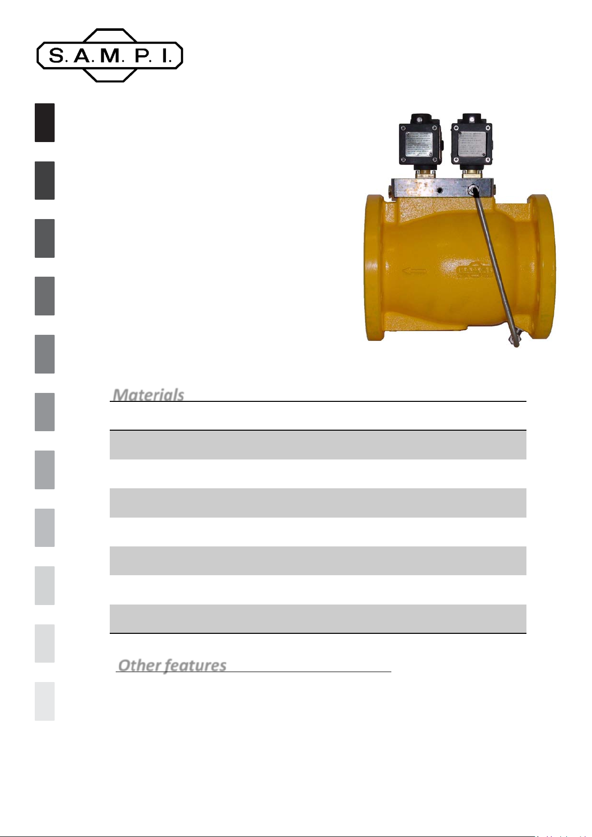
HPV Hydraulic V alve
Specifications Sheet
The operating principle is as follows:
The fluid passes from the “inlet chamber” to the “intermediate
chamber” through a hole in the cap and then through a dirt-proof
filter. Then, it fills the “shutter chamber” through an orifice. Next,
it reaches the solenoid valve holder block through a connecting
hole. Inside the block the fluid finds two paths that run parallel to
each other to reach the “discharge chamber”. The fluid undergoes
to pressure drops along this path depending on the opening level
of the orifices and on the opening of the valves. An intermediate
pressure is established between the delivery pressure and the
discharge pressure, as a result of these pressure drops in the
“shutter chamber”. Together with the contrasting action of the
spring, this pressure moves the axial position of the shutter,
which, in turn, influences the upstream/downstream pressure
values of the valve and therefore also the “shutter chamber”
pressure. Consequently, the equilibrium of the forces is further
modified, which regulates the position of the shutter itself. This
phenomenon ceases once the position of equilibrium is reached,
where the effect of the pressure of the “shutter chamber”, added
to the force of the spring, is equal to the effect of the delivery
pressure.
Materials
Part Material
Body Carbon steel or aluminium
Shutter Alluminium
Fixed parts Aluminium
Other details Stainless steel or carbon steel
Dynamic sealing ring PTFE loaded carbon
Shutter seal packing Viton on incorporated metallic core
Rest of the packing Viton
Other features
The valve works according to three operating regimes;
• Closed;
• Intermediate low flow position;
• High flow position.
The high flow position can, at worst, also coincide with the valve position completely
open, but nonetheless it can be regulated to limit the capacity of the line. The high
and low flow positions are regulated manually from the outside by means of needles
for adjustment.
Page 2
Specifications
Operating temperature range -20°C to 70°C (-4°F to 158 °F)
Max kinematic viscosity 40 cST In the standard version
Max operating pressure (steel body) 10 bar (145 PSI) Up to 70°C (158°F)
Max operating pressure (aluminium body) 10 bar (145 PSI)
Up to 70°C (158°F) – reduces to 5 bar
(73 PSI) up to 125°C (257°F)
Min. valve opening pressure 0,09 bar (1.31 PSI)
Max pressure in no-return function 1,5 bar (21.8 PSI)
Capacity coefficient Cv 270 GPM/PSI
Max flow rate for 0,5 bar (7.3 PSI) pressure
drop
2500 l/min (660 GPM)
With diesel and gasoline (it decrease
in proportion to the viscosity)
Flanges DN4” – ANSI 150 B 16.5 RF SF
Closing time < 4 sec. Adjustable
Opening time From 3 to 6 sec. adjustable
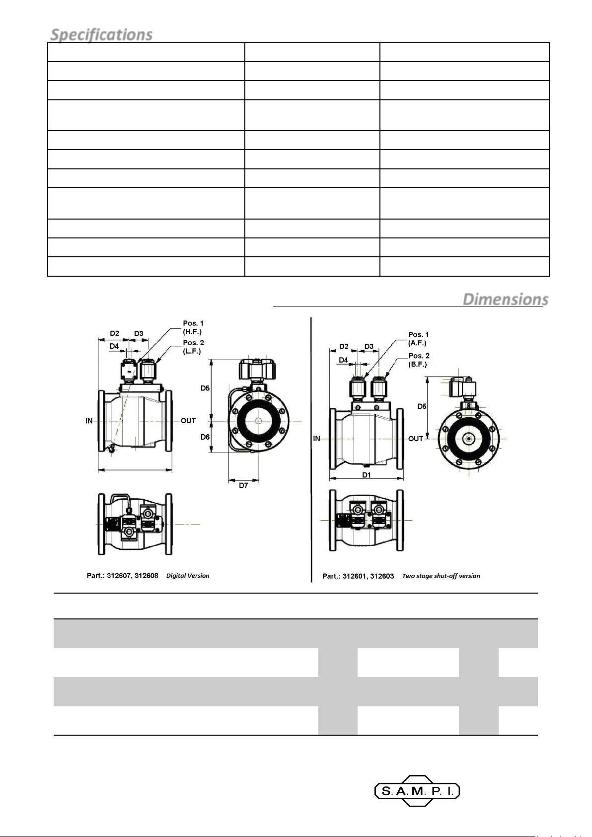
Dimensions
Model Version
312601
312603
312607 Digital
312608 Digital Aluminium
Two
stage
Two
stage
Material
(body)
Aluminium
Carbon
steel
Carbon
steel
mm
in
mm
in
mm
in
mm
in
D1 D2 D3 D4 D5 D6 D7 Flange
280
11.01
280
11.01
280
11.01
280
11.01
108
4.25
108
4.25
117
4.60
117
4.60
80
3.15
80
3.15
71.5
2.81
71.5
2.81
RP ½”
ISO 7/1
234.5
9.23
234.5
9.23
234.5
9.23
234.5
9.23
- -
- - 35 (77)
117
4.60
117
4.60
126
4.96
126
4.96
DN 4”
ANSI
150RF
(Ø 229
mm – 9
SAMPI spa
A unit of IDEX Corporation
Via Amerigo Vespucci, 1
55011 Altopascio (Lucca) – Italy
Phone: +39 0583 24751
Fax: +39 0583 264748
www.sampi.it
Weight
Kg (lbs)
15 (33)
35 (77)
in)
15 (33)
 Loading...