

Page 1

DEDICATED CABINET
OPERATING MANUAL
901 Cambridge Drive
Elk Grove Village, IL 60007
Phone: (847) 364-9787
Fax: (847) 364-9831
Web: www.sammyusa.com
© 2001 Sammy USA Corporation
Page 2

CONTENTS
1. SPECIFICATIONS Page 1
2. GAME PLAY Page 2
3. HANDLING AND INSTALLATION Page 3
4. CONNECTOR TABLES Page 4
5. DIP SWITCH TABLES Page 5
6. LAYOUT OF P.C.BOARD & CONTROL PANEL Page 6
7. TEST MODE Page 7, 8, 9
8. TROUBLE WITH GUN SHOOTING Page 10
9. WARRANTY Page 11
10. ELECTRICAL WIRING DIAGRAM Page 12
Page 3
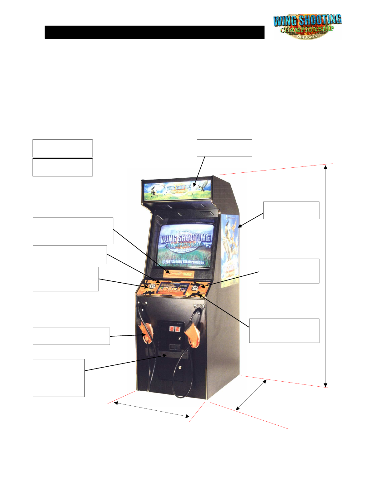
1. SPECIFICATIONS
POWER 120VAC @ 60Hz USA & CANADA
DIMENSIONS Width: 26.5” (673 mm)
Height: 73.5” (1867 mm)
Depth: 33” (838 mm) with Gun Assy = 40” (1016 mm)
WEIGHT 311 lbs (142 kg)
Main PCB, WSC
Part #: 47-10-001
Manual, WSC
Part #: 47-30-311
“PUMP BEFORE
SHOOTING” Decal, WSC
Part #: 47-30-224
Instruction Decal, WSC
Part #: 47-30-210
Start Button Assy,
Hunter 1
Part #: 47-50-013
Sammy 27” Shotgun Assy
Part #: 99-50-310
Marquee, WSC
Part #: 47-30-111
Side Decal, WSC
Part #: 47-30-200
H = 73.5”
(1867 mm)
Start Button Assy,
Hunter 2
Part #: 47-50-015
Control panel Overlay,
UR 25” VIDEO
Part #: 47-30-161
Security Bar KIT,
Mid door
(OPTIONAL)
Part #: 47-70-278
W = 26.5”
(673 mm)
1111
*D = 33”
(838 mm)
*With Gun Assy: D = 40”
(1016 mm)
Page 4

2. GAME PLAY
Wing Shooting Championship is a sports hunting game that has an excit-
ing COMPETITION MODE. Two players can play at the same time in competition mode which is a first time for the market!
HOW TO PLAY
● Insert coin(s)
● Press Hunter 1 or Hunter 2 button to start game.
● Use Sammy 27” Shotgun to select stage and weapon. (Pump the Shotgun before you
shoot the screen each time.) There are 5 kinds of weapons.
PUMP ACTION (5 bullets), SEMI-AUTO (3 bullets)
OVER&UNDER (2 bullets), SIDE BY SIDE (2 bullets)
SINGLE SHOT (1 bullet)
● 6 different bird stages. (GREAT PLAINS QUAIL, RING-NECKED PHEASANT, CAN-
ADA GOOSE, AMERICAN BLACK DUCK, MALLARD DUCK and EASTERN BOB
WHITE QUAIL)
● 12 areas with one bonus stage for each bird. The Bonus stage is CLAY SHOOTING.
Perfect round in bonus stage advances to a SPECIAL STAGE!
2222
Page 5

3. HANDLING AND INSTALLATION
PLEASE TAKE A MOMENT TO READ THE FOLLOWING BEFORE
YOU TURN ON YOUR NEW GAME.
The Wing Shooting Championship video game is an indoor game machine. It is not designed for
outdoor use. Avoid installing the game in the following locations:
Locations subject to rain or water damage
Locations in direct sunlight
Locations subject to extreme heat
Locations near hazardous or flammable liquids or chemicals
You will need the following minimum dimensions for egress into your location:
80 inches in height
30 inches in width
INSTALLATION
Unpack your game carefully. Be careful of the shipping staples. They can be sharp.
Your game is assembled and should not need any assembly.
Level your game using enclosed Leg levelers.
The standard voltage for U.S. and Canada 120V / 125V - 3A; Europe 220V / 240V - 2A.
Use of extension cords is prohibited.
Use only a grounded outlet. YOUR GAME MUST BE GROUNDED!!!
The minimum space required for operation in your locations should be:
THE GAME MUST BE LEVEL. USE A LEVEL TO AVOID NEEDLESS ADJUSTMENTS.
SAFETY PRECAUTIONS
Be sure to turn the power off or unplug the game before working on the unit.
Do not unplug game by pulling on the line cord.
Replace line cord if the insulation is damaged in any way with one of equal quality.
Replace open fuses with same type and rating.
Re-check and re-seat all harness connections.
80” high
30” wide
75” depth
3333
Page 6
4
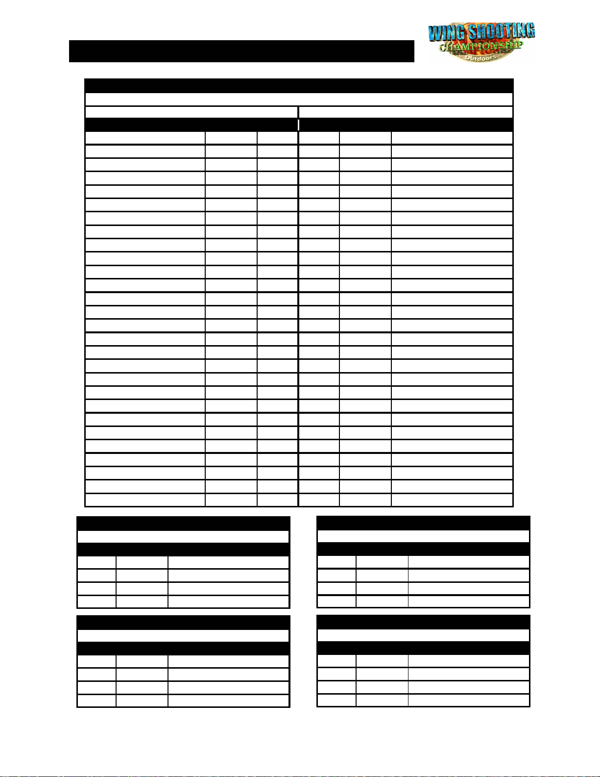
. CONNECTOR TABLES
JAMMA CONNECTOR
MAIN P.C.BOARD
SOLDER SIDE
COMPONENT SIDE
FUNCTION COLOR PIN # PIN # COLOR FUNCTION
GROUND BLK
GROUND BLK
+5VDC RED
+5VDC RED
+12VDC BLU
KEY
COIN METER B
COIN LOCKOUT B
SPEAKER(-) BLK
VIDEO GREEN GRN
VIDEO SYNC WHT
SERVICE CREDIT SWITCH
COIN SWITCH B
2P START BUTTON
GROUND BLK
GROUND BLK
BRN/WHT
A 1
B 2
C 3
D 4
E 5
F 6
H 7
J 8
K 9
L 10
M 11
N 12
P 13
R 14
S 15
T 16
U 17
V 18
W 19
X 20
Y 21
Z 22
a 23
b 24
c 25
d 26
e 27
f 28
BLK GROUND
BLK GROUND
RED +5VDC
RED +5VDC
BLU +12VDC
KEY
COIN METER A
COIN LOCKOUT A
WHT/BLK SPEAKER(+)
RED VIDEO RED
BLU VIDEO BLUE
BLK VIDEO GROUND
WHT/GRY TEST SWITCH
COIN SWITCH A
1P START BUTTON
BLK GROUND
BLK GROUND
CN6 - 4 PIN SUB CONNECTOR
MAIN P.C.BOARD (1P GUN)
PIN # COLOR FUNCTION
1
2
3
4
GREEN PUMP SWITCH
BLACK PUMP SWITCH GND
CN5 - 4 PIN SUB CONNECTOR
MAIN P.C.BOARD (1P GUN)
PIN # COLOR FUNCTION
7
8
9
10
RED +5VDC
WHITE TRIGGER SWITCH
BROWN GROUND
BLUE OPTICAL
CN8 - 4 PIN SUB CONNECTOR
MAIN P.C.BOARD (2P GUN)
PIN # COLOR FUNCTION
1
2
3
4
CN7 - 4 PIN SUB CONNECTOR
MAIN P.C.BOARD (2P GUN)
GREEN PUMP SWITCH
BLACK PUMP SWITCH GND
PIN # COLOR FUNCTION
7
8
9
10
RED +5VDC
WHITE TRIGGER SWITCH
BROWN GROUND
BLUE OPTICAL
4444
Page 7
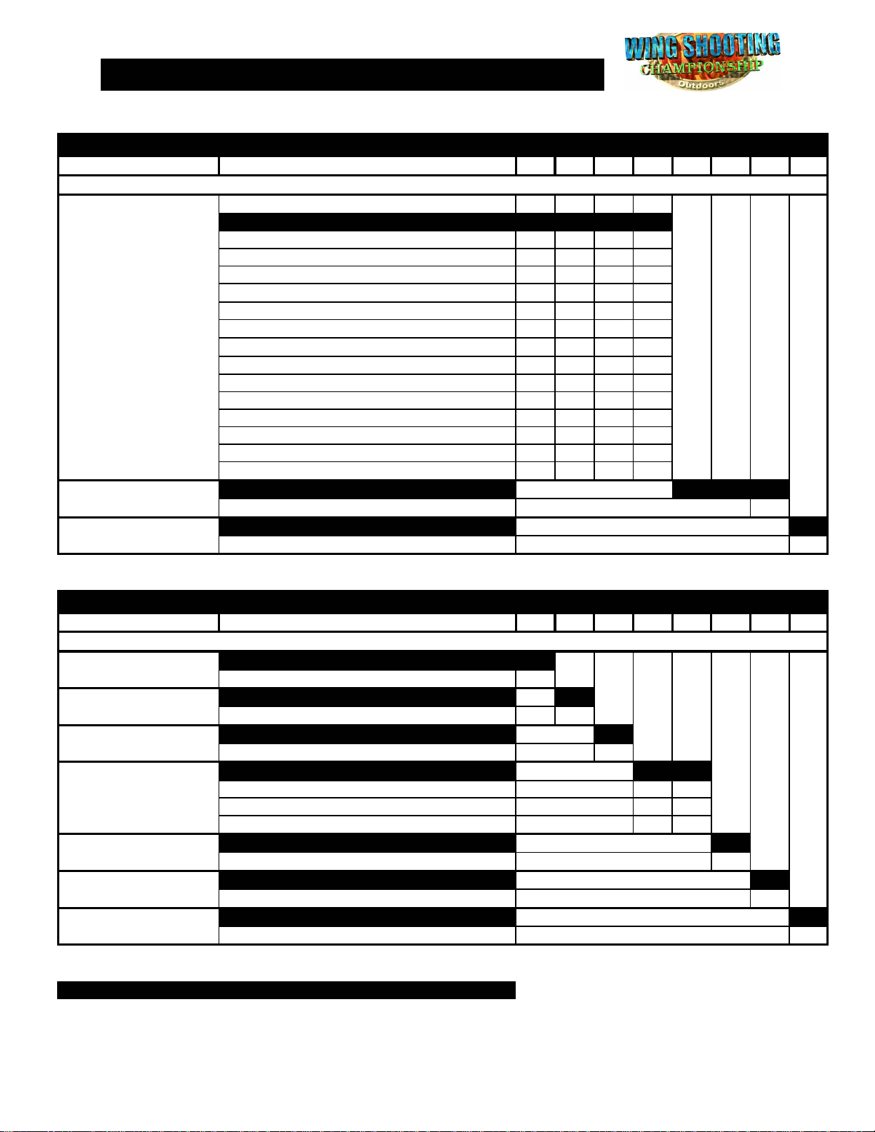
5. DIP SWITCH TABLES
DIP SWITCH 1
FUNCTIONS SETTING 1 2 3 4 5 6 7 8
COIN CHUTE A, B
2 COINS START, 2 COINS CONTINUE ON OFF OFF OFF
2 COINS START, 1 COIN CONTINUE OFF ON OFF OFF
3 COINS START, 2 COINS CONTINUE OFF OFF ON OFF
3 COINS START, 1 COIN CONTINUE ON OFF ON OFF
4 COINS START, 4 COINS CONTINUE OFF ON ON OFF
4 COINS START, 3 COINS CONTINUE ON ON ON OFF
4 COINS START, 2 COINS CONTINUE OFF OFF OFF ON
FREE PLAY ON ON ON ON
NOT USED
TEST MODE
1 COIN START, 1 COIN CONTINUE OFF OFF OFF OFF
3 COINS START, 3 COIN CONTINUE ON ON OFF OFF
4 COINS START, 1 COIN CONTINUE ON OFF OFF ON
1 COIN 2 CREDITS, 1 CREDIT START & CONTINUE
1 COIN 3 CREDITS, 1 CREDIT START & CONTINUE
1 COIN 4 CREDITS, 1 CREDIT START & CONTINUE
1 COIN 5 CREDITS, 1 CREDIT START & CONTINUE
1 COIN 6 CREDITS, 1 CREDIT START & CONTINUE
OFF OFF OFF
OFF OFF
ON ON
DIP SWITCH 2
FUNCTIONS SETTING 1 2 3 4 5 6 7 8
MONITOR SETTING 1
REVERSE VERTICAL ON
MONITOR SETTING 2
ATTRACT SOUND
OFF ON
DIFFICULTY LEVEL
EASY ON OFF
HARD OFF ON
HARDEST ON ON
NOT USED
ON
CHANCES
3 ON
GUN TYPE
"FACTORY INSTALLED" SETTING
NORMAL OFF
NORMAL OFF
REVERSE HORIZONTAL ON
ON OFF
NORMAL OFF OFF
OFF
2 OFF
PUMP ACTION GUN UNIT OFF
HAND GUN UNIT ON
SWITCH POSITIONS
OFF ON OFF ON
ON ON OFF ON
OFF OFF ON ON
ON OFF ON ON
OFF ON ON ON
SWITCH POSITIONS
5555
Page 8
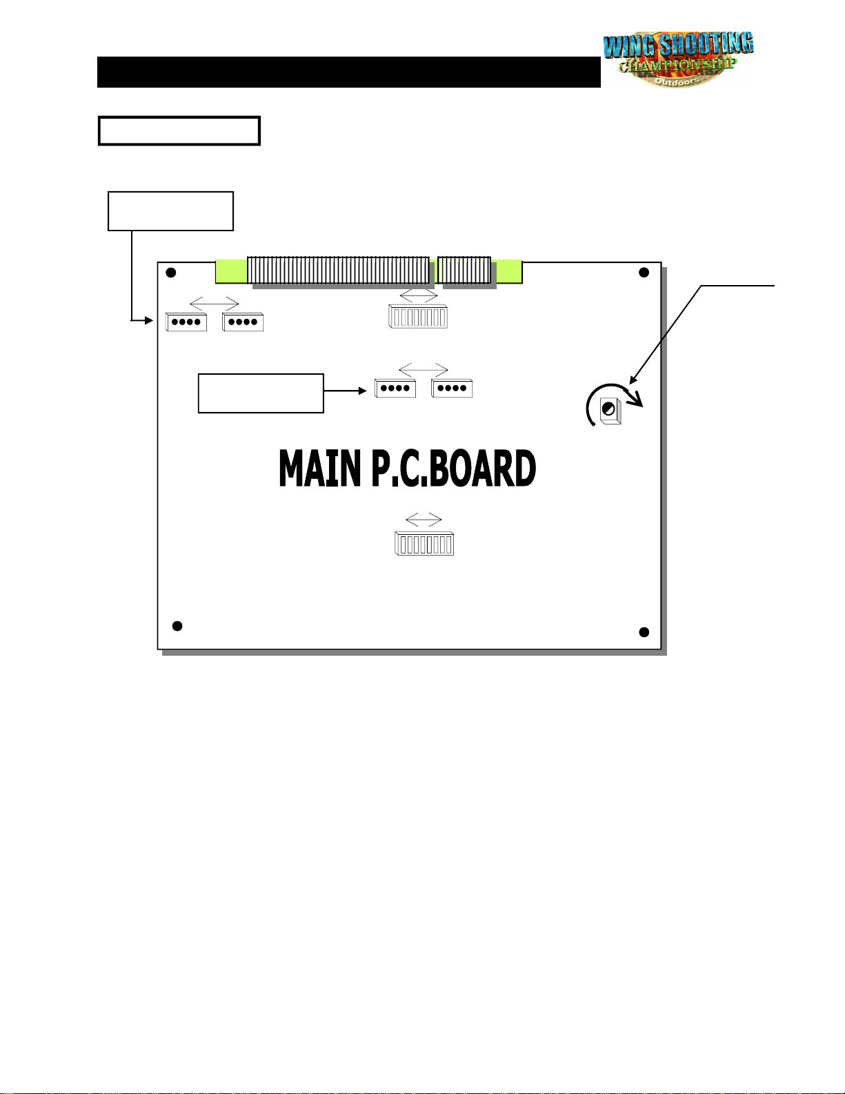
6. LAYOUT OF P.C.BOARD & CONTROL PANEL
MAIN P.C.BOARD
SUB CONNECTOR
4 PINS X 2 (2P GUN)
JAMMA CONNECTOR
VOLUME
1
CN 8 CN 7
SUB CONNECTOR
4 PINS X 2 (1P GUN)
10
1
DIPSW 1
1
CN 6 CN 5
DIPSW 2
8
8 1
ON
OFF
10
MAX
ON
OFF
6666
Page 9
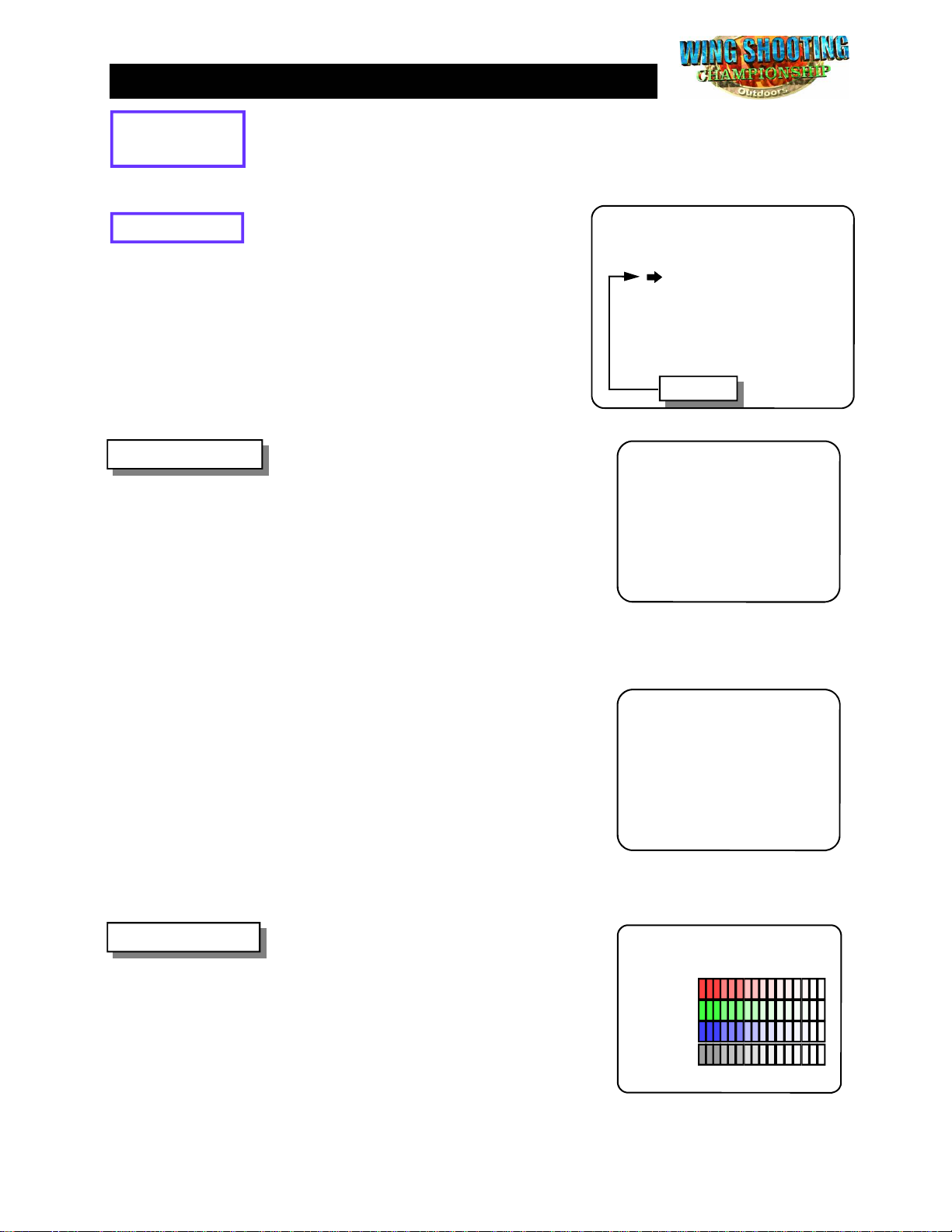
7. TEST MODE
Entering the
TEST MODE
Select TEST
1. GUN MENU
If you need to check the condition of the game circuitry and controls, you can use
the TEST MENU. Turn ON “DIP SWITCH 1, #8” and re-power on the game. The
game will go into TEST MODE (diagnostics) and the screen appears as follows:
Use this screen to choose which of the 7
screens you want to see. Move cursor using
the START BUTTON.
Then pull the TRIGGER to enter the
function.
You can adjust GUN unit in GUN ADJUST
mode.
Gun Adjust
1. Enter TEST MENU and select GUN
ADJUST.
2. Shoot center mark only with gun sight.
SHOOT CENTER MARK ONLY TO ADJUST
TEST MENU
1. GUN MENU
2. COLOR TEST
3. CROSS HATCH
4. I/O TEST
5. SOUND TEST
6. MEMORY TEST
7. OPTIONAL SETTING
8. REBOOT
CURSOR
GUN ADJUST
X
PRESS START BUTTON TO GUN TEST
3. If you need more accuracy, try again.
4. Press START button to save Gun accuracy and enter GUN TEST mode, press
START button again to go back to Main
menu.
2. COLOR TEST
You can test accuracy in GUN TEST mode.
Gun Test
1. At Gun Adjust screen, press START
button to go to test mode.
2. Shoot all around the screen to see
Gun’s accuracy.
3. Press START button to go back to Main
menu.
Use this screen to check the color of
monitor. The color blocks in the center
should be four bands (Red, Green, Blue and
White from top to bottom), each with a color
scale from dark to bright, left to right.
If the screen does not match this description,
adjust the Monitor as described in the
Monitor’s manual.
* Press the START button to exit and go
back to the TEST MENU screen.
X
GUN TEST
PRESS START BUTTON TO EXIT
COLOR TEST
RED
GREEN
BLUE
WHITE
PRESS START BUTTON TO EXIT
7777
Page 10
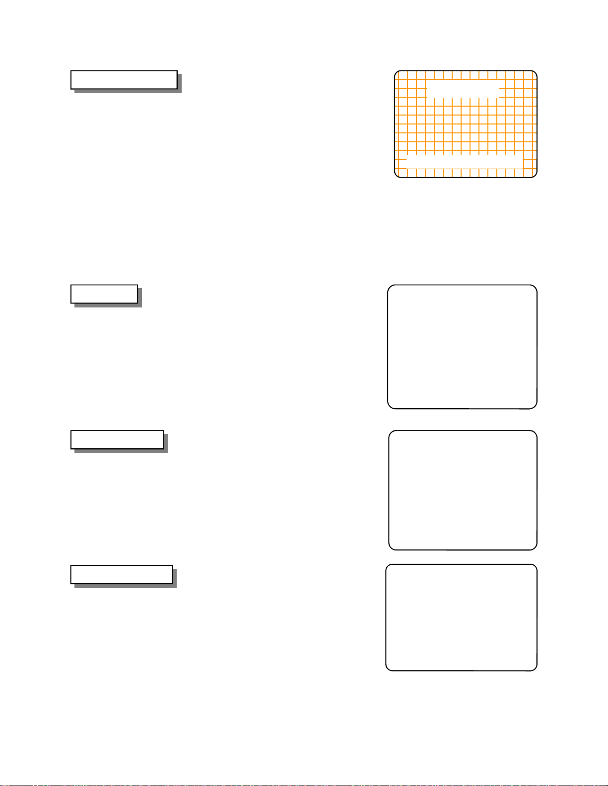
3. CROSS HATCH
Use this screen to check the size of picture.
The CROSS HATCH test pattern has a
White grid on a Black background. Check
following:
- The grid line should be straight, and the
lines should not have excessive
pincushion or barrel distortion.
- “Out”line of grid line is the same size as
“Out”line of game screen. So, “Out” line
should be able to be seen with no overflow
of grid lines on screen.
If these are not as above, adjust the
Monitor as described in the Monitor’s
manual.
* You can exit and go back to the TEST
MENU screen by press START button.
CROSS HATCH
PRESS START BUTTON TO EXIT
4. I/O TEST
5. SOUND TEST
6. MEMORY TEST
Use this screen to check the switches in this
game. To check the functioning of each
switch, activate it and watch the
corresponding OFF letters change to ON.
If the ON and OFF letters do not appear
correctly, check the Harness connections
and Switches.
* Press START button and Gun trigger
simultaneously to exit.
Use this screen to check all game sounds.
Choose a sound with the START buttons.
(Hunter 1 = forward, Hunter 2 = Back) Then
pull the TRIGGER. You can check each
sound in this game.
* Press START button and Gun trigger
simultaneously to exit.
Use this screen to check RAM and ROM
on the Main P.C.B. The Main P.C.B. will
automatically check them when you enter
this screen. If there are no problems, the
word OK will appear on screen.
If you get the word ERROR, check the
mounting of RAMs or ROMs on the Main
P.C.B. and if ERROR reappears, it needs
to be replaced.
I/O TEST
COIN A : OFF
COIN B : OFF
SERVICE : OFF
TEST : OFF
1P GUN
START : OFF
PUMP : OFF
TRIGGER : OFF
PRESS START & GUN TRIGGER TO EXIT
2P GUN
START : OFF
PUMP : OFF
TRIGGER : OFF
SOUND TEST
SOUND CODE 000
BLAK_SHOT
PRESS START BUTTON TO CHOOSE
PRESS GUN TRIGGER TO PLAY
PRESS START & GUN TRIGGER TO EXIT
MEMORY TEST
WORK RAM : OK
BACKUP RAM : OK
ROM (U06) : OK
ROM (U07) : OK
* This mode will automatically exit after testing is finished.
8888
Page 11
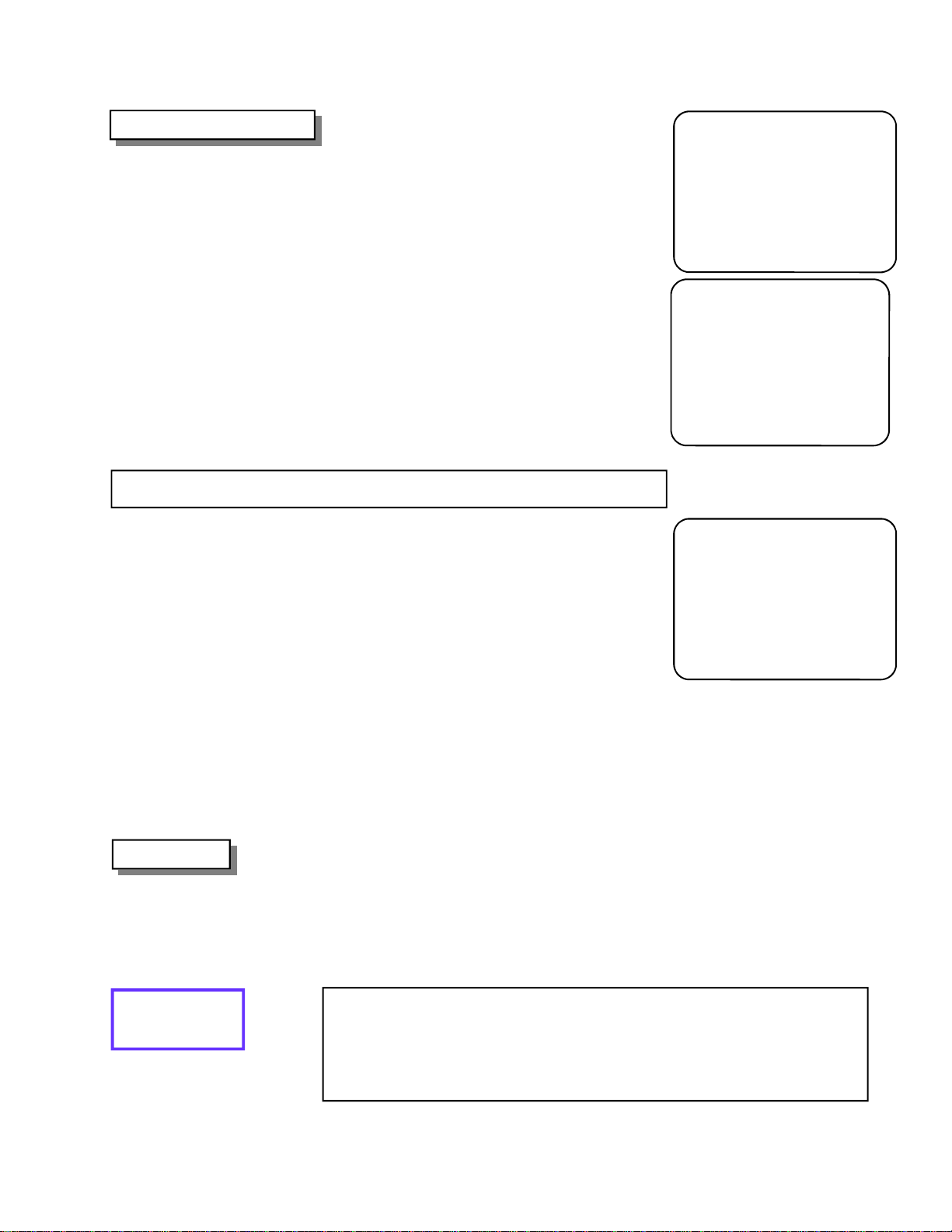
7. OPTIONAL SETTING
HIGH SCORE CLEAR
If you desire to clear HIGH SCORE data, do the
following.
HOW TO SET UP
1. Enter TEST MENU and select OPTIONAL
SETTING.
2. Press START BUTTON to choose HIGH
SCORE CLEAR.
3. Select YES by pressing START BUTTON
and pressing GUN TRIGGER to clear HIGH
SCORE data.
4. The screen will return to previous screen
automatically after clearing HIGH SCORE
data.
NOTE: Do not proceed if Gun test is accurate.
OPTIONAL SETTING
1. HIGH SCORE CLEAR
2. GUN ADJUST DEFAULT
3. RETURN TO TEST MENU
PRESS START BUTTON TO CHOOSE
PRESS GUN TRIGGER TO SELECT
HIGH SCORE CLEAR
ARE YOU SURE YOU WANT TO CLEAR
HIGH SCORE?
YES
NO
PRESS START BUTTON TO CHOOSE
PRESS GUN TRIGGER TO SELECT
8. REBOOT
GUN DATA DEFAULT
If you have problem with Gun sighting , you may
have to clear the Gun data.
After clearing Gun data, the game will be reset
to factory default setting.
See the following for how to clear saved data.
1. Enter TEST MENU and select OPTIONAL
SETTING.
2. Press START BUTTON to choose GUN ADJUST DEFAULT.
3. Select YES by pressing START BUTTON
and pressing GUN TRIGGER to clear Gun
data.
4. The screen will return to previous screen
automatically after clearing Gun data.
Use this screen to go back to normal game
mode. After selecting this function, the game will
automatically take you to the normal game
screen.
Make sure to turn OFF “DIP SWITCH 1, #8” or
you will return to test mode upon powering on.
GUN ADJUST DEFAULT
ARE YOU SURE YOU WANT TO SET
GUN ADJUST DEFAULT?
YES
NO
PRESS START BUTTON TO CHOOSE
PRESS GUN TRIGGER TO SELECT
Returning to
GAME MODE
You can return to normal game mode by doing one or the other of the
following:
Turn OFF “DIP SWITCH 1, #8” and re-power on the game.
Select REBOOT at TEST MENU. (But you will have to make sure to turn OFF
“DIP SWITCH 1, #8”.)
9999
Page 12
8. TROUBLE WITH GUN SHOOTING
If you have trouble because you can’t shoot to the corner of the screen, you may
have to adjust the monitor brightness. Turn up the monitor brightness until you can
shoot the corner of screen.
Plus, monitors tend to develop a magnetic field from continuous use, which would
cause the gun unit not to function properly. Therefore, it is recommended that the
monitor is demagnetized [degaussed] every so often in order to keep the gun unit
functioning properly.
In addition, the following conditions of the monitor may result in Gun shooting problems:
● Picture burned on monitor screen
● Over gauzed monitor
● Non adjustable brightness feature
Also, the following conditions of the cabinet may result in Gun shooting problems.
● Combination of low performing adjustable brightness
monitor and low reflection mirror
● Dirty monitor screen or monitor grass
GUNSHOT ACCURACY IMPROVEMENT
If you have trouble because you can’t calibrate the gun unit properly. For
example you can’t shoot corner of screen or you can shoot only in the center of the screen, do the following:
1) CHECK THE +5V LINE ON THE PCB. YOU CAN CHECK VOLTAGE AT THE
JAMMA EDGE CONNECTOR BETWEEN PIN #2 AND #3.
2) ADJUST +5V LINE TO +5.25V BY TURNING UP POTENTIOMETER ON THE
POWER SUPPLY.
WARNING: DO NOT TURN UP VOLTAGE MORE THAN +5.25V OTHERWISE
YOUR PCB WILL SUSTAIN SERIOUS DAMAGE.
3) ENTER BACK UP CLEAR IN TEST MODE, THEN SELECT YES TO CLEAR
BACK UP DATA.
NOTE: YOU DON’T HAVE TO DO “GUN ADJUST” IN TEST MODE.
4) ENTER GUN TEST IN TEST MODE TO CHECK GUNSHOT. IF THE GUNSHOT IS
NOT CORRECTED REPEAT STEP #3.
10
10
1010
Page 13
9. WARRANTY
Limited warranty, Repair and Return Policy
Sammy USA Corporation warrants all products to be free from defective materials and workmanship
for a period of thirty (30) days from the Sammy USA Corporation invoice date unless otherwise
specified in writing by Sammy USA Corporation. The extent of this warranty applies to all electronic
assemblies only, and does not include lamps and fuses.
This limited warranty is invalid for any product that upon examination, is deemed to have been subject
to misuse, improper repair or installation, neglect or violation of specification or other instructions
published by Sammy USA Corporation.
There are no additional warranties which extend beyond those limited warranties described above.
The limited warranties described above shall be in lieu of any other warranty, express or implied,
including but not limited to any implied warranty of merchantability or fitness for a particular purpose.
Return Merchandise Authorization
1. Contact your authorized Sammy USA distributor to receive a Return Merchandise Authorization for
return.
2. You must obtain RMA numbers from Sammy USA Corporation through an authorized Sammy USA
distributor. Please have your serial number available when calling for an RMA number.
3. All items must have an RMA number marked clearly on the outside of the package.
4. Products must be shipped prepaid. Products returned without an RMA number will not be
accepted.
5. Credits to accounts are subject to inspection of products for damage and suitability for resale.
11
11
1111
Page 14
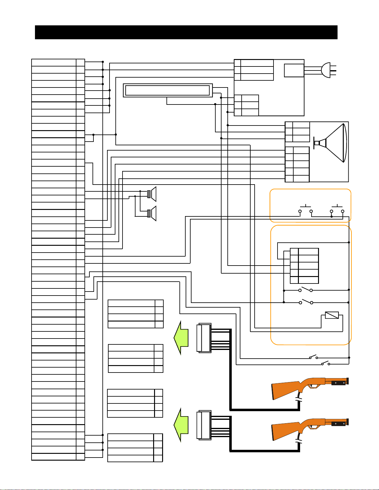
10. ELECTRICAL WIRING DIAGRAM (WSC, DEDICATED CABINET)
JAMMA Connector (56 pins)
on Main CPU Board
GND 1
GND A
GND 2
GND B
+5VDC 3
+5VDC C
+5VDC 4
+5VDC D
5
E
+12VDC 6
+12VDC F
KEY 7
KEY H
COIN METER A 8
J
COIN LOCKOUT A 9
K
SPEAKER (+) 10
SPEAKER (-) L
11
M
VIDEO RED 12
VIDEO GREEN N
VIDEO BLUE 13
VIDEO SYNC P
VIDEO GND 14
SERVICE CREDIT SWITCH R
TEST SWITCH 15
S
COIN SWITCH A 16
T
1P START BUTTON 17
2P START BUTTON U
18
V
19
W
20
X
21
Y
22
Z
23
a
24
b
25
c
26
d
GND 27
GND e
GND 28
GND f
Fluorescent Lamp Assy, Marquee
Sub Connector CN6 (4 pins)
on Main CPU Board (1P GUN)
1
1P PUMP SW 2
1P PUMP SW GND 3
4
Sub Connector CN5 (4 pins)
on Main CPU Board (1P GUN)
+5VDC 7
1P TRIGGER SW 8
GROUND 9
OPTICAL 10
Sub Connector CN8 (4 pins)
on Main CPU Board (2P GUN)
1
2P PUMP SW 2
2P PUMP SW GND 3
4
Sub Connector CN7 (4 pins)
on Main CPU Board (2P GUN)
+5VDC 7
2P TRIGGER SW 8
GROUND 9
OPTICAL 10
Speaker
8 ohm, 4W
Speaker
8 ohm, 4W
Gun Connector, 1P
(JST 10 PIN)
Gun Connector, 2P
(JST 10 PIN)
12
12
1212
9 PIN CONNECTOR
1 +5VDC (RED)
2 GROUND (BLACK)
3 +12VDC (YELLOW)
3 PIN CONNECTOR
1 AC115V
2 EARTH
3 AC115V
Power Supply UNIT
(BS200P)
+5VDC (20A)
+12VDC (8A)
AC
115V IN
1 AC115V
2 EARTH
3 AC115V
10 RED
9 GREEN
8 BLUE
7 GND
1 SYNC
Switch Bracket
Service Credit
Switch
Coin Door
8 COIN IN
7 GND
6 AC115V
4 AC115V
3 NEUTRAL
A/C Line cord
BLK
GRN
WHT
25” TV
MONITOR
ASSY
TEST
Switch
Option 9 PIN
connector
(DBA Mars
AE2451)
Coin Switch
Coin Switch
1P Start Button (Hunter 1)
2P Start Button (Hunter 2)
GUN ASSY, 1P
GUN ASSY, 2P
 Loading...