

Page 1
INSTRUCCIONES - USERS MANUAL - GEBRAUCHSANWEISUNG MODE D’EMPLOI - INSTRUZIONI PER L’USO - MANUAL DE INSTRUÇÕES
BE-10/C
BE-20/C/I
BE-30/C/I
BE-40/C
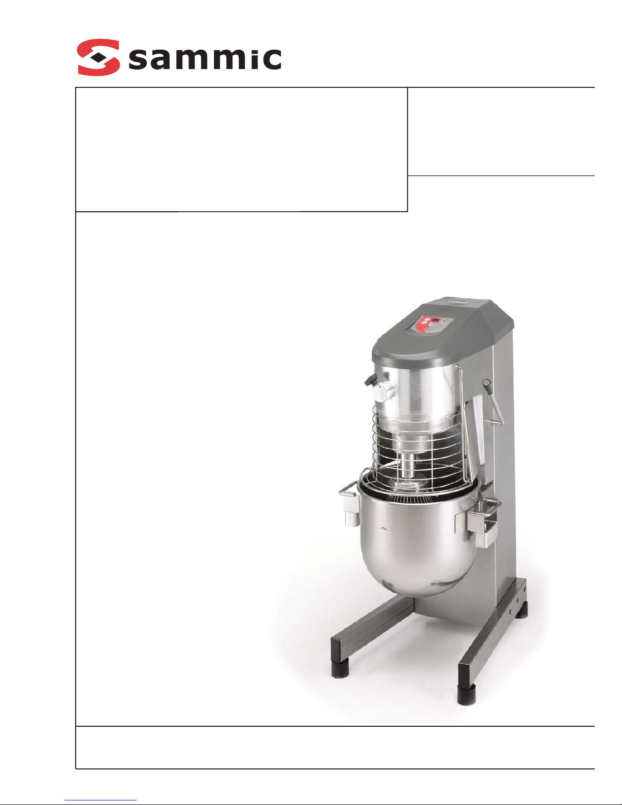
Batidoras-mezcladoras
Mixers
Rühr-, Schlag-, Knetmaschinen
Impastatrici
Batteurs-melangeurs
Batedeiras misturadoras
Page 2
INDICACIONES PARA EL MARCADO CE
Cada máquina lleva las siguientes indicaciones:
-Nombre y dirección del fabricante: SAMMIC
S.L - Basarte 1 Azkoitia. Gipuzkoa (SPAIN)
-Marca "CE"
-Se indica el modelo de máquina en el apartado
siguiente
-El número de serie se indica en la hoja de
garantía y en la declaración de conformidad.
MODELOS
Este manual describe la instalación,
funcionamiento y mantenimiento de las batidoras
planetarias BE-10, BE-10C, BE-20, BE-20C, BE20I, BE-30, BE-30C, BE-30I, BE-40 y BE-40C.
La referencia del modelo y sus características
se indican en la placa de identificación
colocada en la máquina.
Estas batidoras están diseñadas y fabricadas
de acuerdo a las siguiente Directivas y Normas
Europeas:
Directiva de máquinas 98/37/CEE
Directiva de baja tensión 73/23/CEE
Directiva de compatibilidad electromagnética
89/336/CEE
Norma EN-454: Batidoras Planetarias.
Requisitos de seguridad e higiene.
Indices de protección según la norma EN 60529
IP Máquina IP Mandos
BE-10 / BE-10C 21 55
BE-20 / BE-20C / BE-20I 23 55
BE-30 / BE-30C / BE-30I 23 55
BE-40 / BE-40C 23 55
INSTALACION
Para conseguir las mejores prestaciones, así
como una buena conservación de la máquina,
hay que seguir cuidadosamente las
instrucciones contenidas en este manual.
EMPLAZAMIENTO
Roscar o desenroscar las tres patas regulables
para poner la máquina a nivel y asegurar una
buena estabilidad a la máxima velocidad.
CONEXIÓN ELÉCTRICA
1. Características.
- La batidora se suministra para tensión de
230V 50-60 Hz monofásica.
- En todos los modelos el motor es trifásico y
está comandado por un variador de
frecuencia.
- No manipular en ningun caso la
configuración del variador.
- ES OBLIGATORIA LA CONEXION CON
TIERRA. El variador está provisto de un filtro
que conduce las perturbaciones existentes a
tierra. Por este motivo puede ocurrir que el
diferencial de la instalación actúe de forma
intempestiva. Se recomienda utilizar un
diferencial propio para la máquina o uno del
tipo "súper inmunizado" .
- Preparar una toma de corriente mural con
protección diferencial y magneto-térmica de
2P de 20A con su clavija correspondiente.
Colocar el interruptor o la clavija de forma
accesible para la desconexión de la
máquina.
2. Características del cable:
Las batidoras SAMMIC se suministran con un
cable eléctrico de 1,5 m de largo, con
recubrimiento termo plástico.
ES OBLIGATORIA LA CONEXION CON
TIERRA. El hilo de toma-tierra de la máquina
está señalizado.
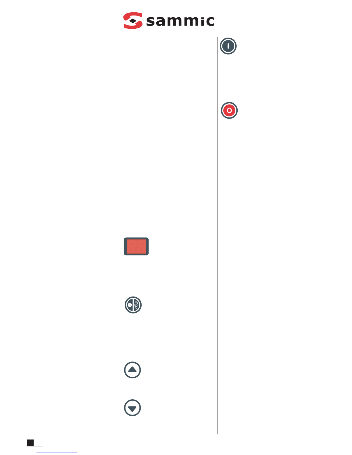
FUNCIONES DEL CONTROL ELECTRONICO
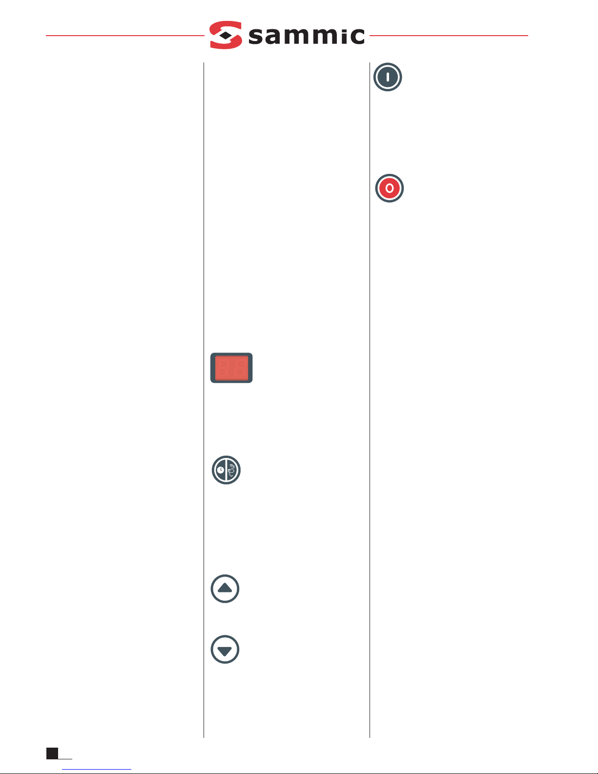
Ver fig. 1 Visor (L)
Visualiza el tiempo de funcionamiento, la
velocidad y los diferentes avisos. Al conectar la
máquina, el visor visualiza dos rayas
horizontales de espera y los led "tiempo" (1) y
"velocidad" (2) están apagados.
Ver fig. 1 Función (A)
Pulsándolo seleccionamos la función a visualizar,
tiempo o velocidad. Tenemos seleccionado
tiempo si el piloto (1) esta encendido. Si
volvemos a pulsar "Función" (A) pasamos a ver la
velocidad y el piloto (2) se enciende. Puede
pulsarse con el motor en marcha o parado.
Ver fig. 1 Subir (H)
Cada pulsación incrementa el valor
seleccionado en el visor.
Ver fig. 1 Bajar (H)
Cada pulsación decrementa el valor
seleccionado en el visor.
Ver fig. 1 Marcha (B)
Pone en marcha el motor si se la rejilla está
cerrada y el caldero en su posición. Si falta
alguna de las dos seguridades y pulsamos
marcha, el visor visualiza "SE" (seguridad)
indicando que falta alguna seguridad para el
arranque.
Ver fig. 1 Parada (G)
La primera pulsación detiene el motor, el visor
empieza a parpadear indicando que está en
espera. Sigue guardando los valores de tiempo
y velocidad. Una vez transcurridos 3 minutos
o volviendo a pulsar "parada" la máquina
pierde esos valores y pasa al estado inicial.
Veremos dos rayas horizontales.
FUNCIONAMIENTO
Control de Tiempo: Se visualiza cuando el
piloto "tiempo" (1) está encendido. Se puede
modificar tanto en marcha como parado.
- Funcionamiento continuo: una raya girando
en el visor indica que lo tenemos
seleccionado.
- Funcionamiento temporizado: Desde ½
minuto hasta los 30 minutos. Entre ½ y 10
minutos seleccionamos el tiempo de ½ minuto
en ½ minuto. A partir de 10, en minutos. El
visor visualiza el descontaje de la misma
forma excepto el ultimo minuto, que
descuenta en segundos (identificado con la
iluminación de un punto el parte inferior
derecha del visor). Cuando el tiempo
programado finaliza, la máquina se detiene y
se oye un pitido.
Control de Velocidad: Se visualiza con el
piloto "velocidad" (2) encendido y se pueden
seleccionar de 1 a 10 velocidades distintas.
Estando el motor en marcha, se visualiza la
velocidad, al cabo de 5 sg automáticamente
pasa a visualizar el tiempo. Se puede
modificar tanto con el motor en marcha como
parado.
Espera: Se visualiza con dos rayas
horizontales. Si pulsamos marcha tenemos
funcionamiento continuo y velocidad mínima.
Ahorro: Estando la máquina parada si en 5
minutos no hacemos nada en el visor se apaga
y visualiza solo un punto. Pulsando cualquier
tecla se enciende de nuevo.
2
ES
Page 3

3
ES
PUESTA EN MARCHA
Antes de utilizar por primera vez la máquina,
limpiar la zona de contacto con alimentos con
agua jabonosa (templada), aclarar y dejarla secar.
1. COLOCACIÓN DEL CALDERO
- Poner el soporte de caldero en la posición
baja.
- El caldero se ajusta al soporte por tres puntos
de fijación.
- Colocar el caldero de forma que la etiqueta “MAX”
quede visible.
- Cuidar que las partes en contacto estén
limpias.
- Para sacar el caldero, elevarlo y tirar hacia
fuera.
2. COLOCACIÓN DE LOS ÚTILES
- Poner el soporte de caldero en la posición
baja.
- Enganchar el eje del útil en el porta-útil.
- Para facilitar este proceso, colocar previamente
el útil en el caldero.
3. SELECCIONAR EL TIEMPO Y LA VELOCIDAD.
Adaptar la velocidad y el útil al trabajo que se
va a realizar, teniendo en cuenta que la fuerza
de arrastre disponible (par) aumenta cuando
disminuye la velocidad.
4. FUNCIONAMIENTO
La batidora sólo se pone en marcha si el
caldero está en la posición alta con la etiqueta
“MAX” en frente y la rejilla de seguridad bajada.
Si falta alguna de las seguridades al pulsar
marcha la máquina no arranca y se visualiza
"SE".
5. C
APACIDADES MÁXIMAS
La capacidad de trabajo de una batidora está
en función de:
-la herramienta utilizada,
-la naturaleza, cantidad y densidad de la masa
-la velocidad adecuada.
La superación de las cantidades máximas
aconsejadas va en perjuicio del trabajo y de
la longevidad de la máquina.
FUNCIONAMIENTO DEL TOMA ACCESORIOS
1. Es obligatorio desconectar la máquina de
la red.
2. Introducir el accesorio
3. Girar el accesorio hasta que este encaje en
el eje de la batidora e introducirlo hasta el
fondo, haciendo coincidir la guía del
accesorio en la muesca del toma accesorios.
4. Girar la maneta lateral hasta que el accesorio
quede perfectamente fijado.
5. Comprobar que las seguridades de la
batidora están activadas, es decir que el
caldero está en su posición más elevada y el
protector bajado.
6. Completar el accesorio si es necesario
(rejillas, discos...).
7. Conectar la máquina
8. Al terminar el trabajo volver a desconectar la
batidora de red y desmontar el accesorio y
limpiar la máquina.
ATENCION:
- Tener cuidado a la hora de manipular los
accesorios debido a que están provistos
de cuchillas y elementos afilados.
- No introducir NUNCA la mano ni cualquier
utensilio por las bocas de salida o entrada
de los accesorios, a fin de evitar accidentes
o el deterioro de los mismos.
HERRAMIENTA RANGO DE VELOCIDAD
CR-143 Del 6 al 10 según discos
HM-71 Del 1 al 5 según tipo de carne
P-132 Del 4 al 8
MANTENIMIENTO
ATENCIÓN: Antes de cualquier intervención
para la limpieza, revisión o reparación de la
batidora, obligatoriamente hay que
desconectar la batidora de la red.
- El caldero y los útiles de trabajo, por estar en
contacto con la masa, se deben limpiar
inmediatamente después de su utilización, con
agua caliente y un detergente admitido en
alimentación. Después, aclarar con abundante
agua caliente y desinfectar con un paño suave
impregnado en alcohol etílico (90º).
- El exterior de la máquina NO SE DEBE
limpiar con un chorro directo de agua.
Emplear para su limpieza un paño húmedo y
cualquier detergente habitual.
- Vigilar periódicamente que las rejillas de
ventilación traseras no se obstruyan.
- Secar y engrasar con vaselina las guías del
soporte.
- Nivel de ruido de la máquina, en marcha,
colocada a 1,6 m de altura y 1 m de distancia,
inferior a 75 dB(A). Ruido de fondo: 32 db(A).
INCIDENCIAS DE FUNCIONAMIENTO:
- El variador de velocidad electrónico dispone
de protecciones ante fluctuaciones de tensión
e intensidad, o calentamientos excesivos. En
el caso de que la máquina se pare y se
visualice "E1" en el display, indica que alguna
protección ha actuado. Para salir de este
estado pulsar "parada" (G) o desconectar la
máquina de la red y esperar.
- El caldero está en posición y la rejilla bajada.
Pulsamos marcha y en el visor aparece "SE".
Algún detector estropeado o suelto.
- El sentido de giro del planetario no es el
correcto. Cambiar las fases del motor en la
salida del variador.
- En caso de deterioro del cable de
alimentación, su sustitución deberá ser
realizada en un servicio técnico autorizado
por SAMMIC S.L.
- La batidora tiene más par trabajando a baja
velocidad. Si se ve que la máquina está
teniendo problemas por frenadas, reducir la
velocidad. Si los problemas persisten parar y
revisar la cantidad o la calidad de la masa o
mezcla.
EQUIPAMIENTO
Standard
El equipamiento standard incluye un caldero
inoxidable y tres útiles diferentes:
1. Gancho amasador, de forma espiral, para
todas las masas duras.
2. Paleta mezcladora, para masas blandas de
pastelería.
3. Revolvedora, para todo tipo de emulsiones.
Accesorios opcionales: (ver pag.14)
- Equipo de 10 litros para las batidoras BE-20,
BE-20 I y BE-20 C.
- Equipo de 10 litros para las batidoras BE-30,
BE-30 I y BE-30 C.
- Equipo de 20 litros para la batidora BE-40.
- Cortadora-Ralladora CR-143, para cortar
hortalizas y rallar pan, queso, chocolate, etc.
- Picadora de carne HM-71, para picar toda
clase de carnes crudas y cocidas.
- Prensapurés P-132, para convertir en puré
toda clase de potajes y salsas.
OTRAS OBSERVACIONES IMPORTANTES
Este aparato no esta destinado para ser usado
por personas (incluido niños) cuyas
capacidades físicas, sensoriales o mentales
estén reducidas, o carezcan de experiencia o
conocimiento, salvo si han tenido supervisión o
instrucciones relativas al uso del aparato por
una persona responsable de su seguridad.
Page 4
ES
4
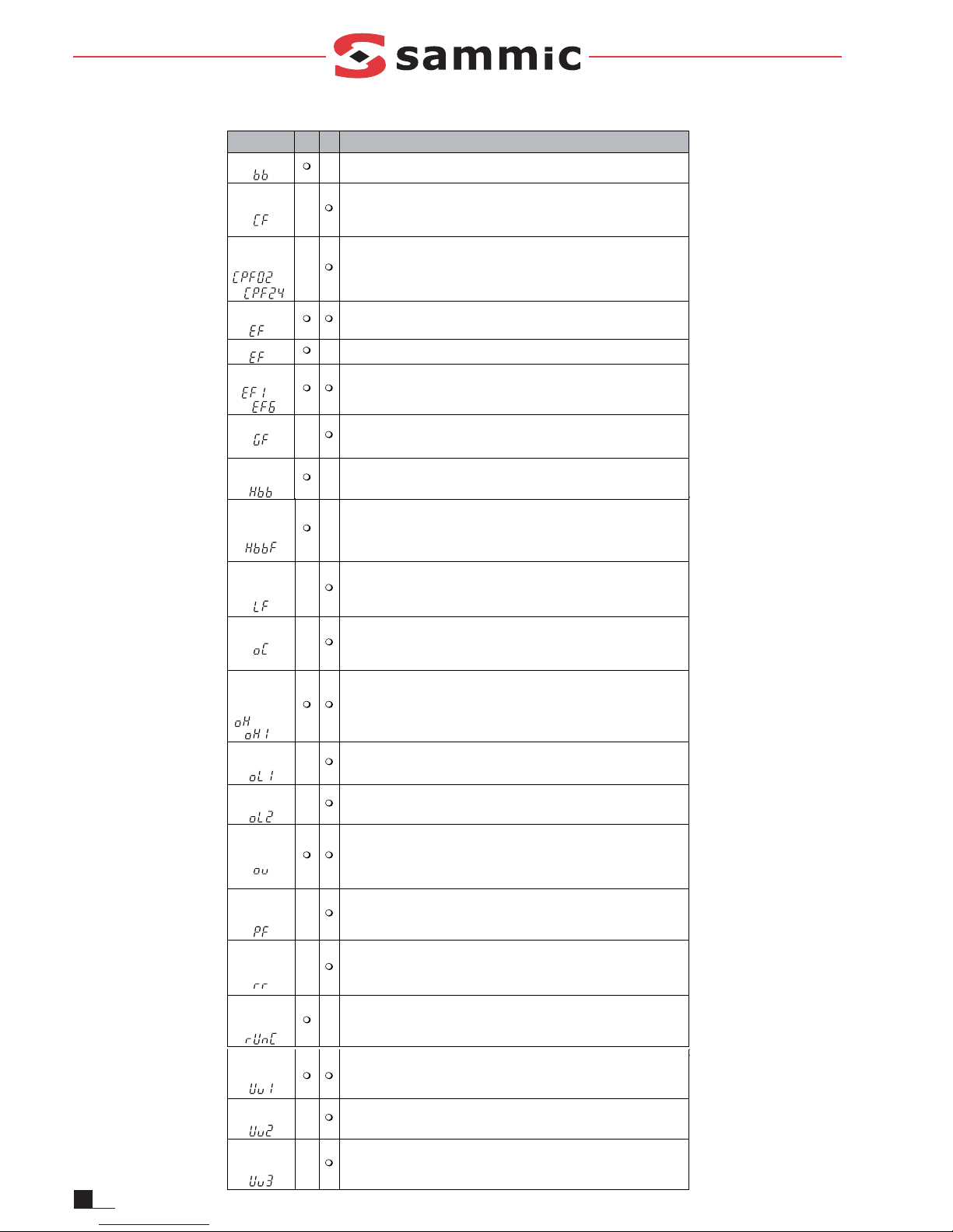
Fallo de
desconexión
de seguridad
La salida del variador se desactiva cuando sólo está abierta una de las entradas
de desconexión de seguridad (normalmente ambas señales de entrada H1 y H2
deben estar abiertas).
Ŗ Un canal está averiado internamente y no se desconecta, aunque se quite la
señal externa.
Ŗ Sólo un canal está desactivado por el controlador superior.
Pérdida
de fase
de salida
Ŗ El cable de salida está desconectado o el bobinado del motor está dañado.
Ŗ Cables flojos en la salida del variador.
Ŗ El motor es demasiado pequeño (menos del 5% de la corriente del variador).
Sobrecorriente
Ŗ Cortocircuito o fallo de tierra en la salida del variador
Ŗ La carga es demasiado pesada.
Ŗ Los tiempos de aceleración/deceleración son demasiado cortos.
Ŗ Configuración errónea de datos de motor o curva V/f.
Ŗ Se ha activado un contactor magnético en la salida.
Sobretempera-
tura del
disipador
térmico
Ŗ La temperatura circundante es demasiado alta.
Ŗ El ventilador de refrigeración se ha parado.
Ŗ El disipador térmico está sucio.
Ŗ El flujo de aire al disipador térmico está bloqueado.
Sobrecarga
del motor
Ŗ La carga del motor es demasiado pesada.
Ŗ El motor opera a baja velocidad con una carga pesada.
Ŗ Los tiempos de ciclo de aceleración/deceleración son demasiado cortos.
Ŗ Se ha configurado una corriente nominal de motor incorrecta.
Sobrecarga
del variador
Ŗ La carga es demasiado pesada.
Ŗ La capacidad del variador es demasiado pequeña.
Ŗ Par demasiado alto a velocidad baja.
Sobretensión
de c.c.
La tensión del bus de c.c. ha subido demasiado.
Ŗ El tiempo de deceleración es demasiado corto.
Ŗ La prevención de bloqueo está desactivada.
Ŗ Chopper de freno/resistencia rotos.
Ŗ Control de motor inestable en OLV.
Ŗ Tensión de entrada demasiado alta.
Pérdida
de fase
de entrada
Ŗ Caída de tensión de entrada o desequilibrio de fases.
Ŗ Se ha perdido una fase de entrada.
Ŗ Cables flojos en la entrada del variador.
Fall o
de transistor
de frenado
El transistor de freno interno está defectuoso.
Reset de fallo
durante
la marcha
Se recibió un reset de fallo cuando estaba activo un comando RUN.
o bien
Baja tensión
de c.c.
La tensión del bus de c.c. está por debajo del nivel de detección de tensión baja
(L2-05).
Ŗ Fallo de la fuente de alimentación o se ha perdido una fase de entrada.
Ŗ La tensión de alimentación es demasiado débil.
Tensión baja
del controlador
La tensión de alimentación del controlador del variador es demasiado baja.
Fallo del
circuito de
carga de c.c.
El circuito de carga del bus de c.c. está averiado.
Visualizador
LED
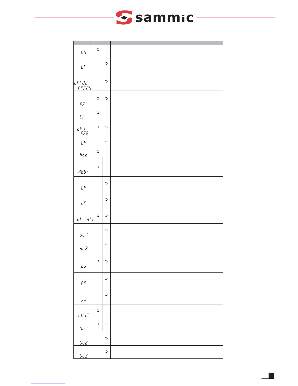
ALM FLT Causa
Baseblock
La función de baseblock se asigna a una de las entradas digitales y la entrada
se desconecta. El variador no acepta comandos de marcha RUN.
Fall o
de control
Se ha alcanzado el límite de par en la deceleración durante más de 3 segundos
en control vectorial lazo abierto
Ŗ La inercia de la carga es demasiado grande.
Ŗ El límite de par es demasiado bajo.
Ŗ Los parámetros de motor son erróneos.
Fall o
del circuito
de control
Hay un problema en el circuito de control del variador.
Fallo externo
de opción
El controlador superior ha activado un fallo externo a través de una tarjeta opcional.
Fallo externo
Se han introducido un comando de marcha directa y otro de marcha inversa simultaneamente durante más de 500 ms. Esta alarma detiene el motor en marcha.
Fallos
externos
Ŗ Se ha activado un fallo externo por un dispositivo externo mediante una de las
entradas digitales S1 a S6.
Ŗ Las entradas digitales están configuradas incorrectamente.
Fallo de tierra
La corriente de fugas a tierra ha superado el 50% de la corriente nominal
de salida del variador.
Ŗ El cable o el aislamiento del motor está roto.
Ŗ Excesiva capacitancia parásita en la salida del variador.
Desconexión
de seguridad
Ambas entradas de desconexión de seguridad están abiertas. La salida del
variador se ha desactivado de forma segura y el motor no se puede arrancar.
a
a
CODIGOS DE ERRORES DEL VARIADOR
Page 5
5
EN
CE MARKING INSTRUCTIONS
All machines carry the following information:
- Name and address of the manufacturer: SAMMIC
S.L - Basarte 1 Azkoitia. Guipuzcoa (SPAIN)
- "CE" mark
- The machine model is shown in the next
section
- The serial number is shown on the guarantee
sheet and on the declaration of conformity.
MODELS
This manual describes the installation,
operation and maintenance of the BE-10, BE10C, BE-20, BE-20C, BE-20I, BE-30, BE-30C,
BE-30I, BE-40 and BE-40C planetary mixers.
The reference number of the model and its
specifications are shown on the identification
plate attached to the machine.
These mixers are designed and manufactured
in accordance with the following European
Directives and Standards:
Machines Directive 98/37/CEE
Low Voltage Directive 73/23/CEE
Electromagnetic Compatibility Directive 89/336/CEE
EN-454 Standard: Planetary mixers. Safety and
Hygiene Requisites.
Protection classes as per EN 60529
IP Machine IP Controls
BE-10 / BE-10C 21 55
BE-20 / BE-20C / BE-20I 23 55
BE-30 / BE-30C / BE-30I 23 55
BE-40 / BE-40C 23 55
INSTALLATION
Please follow the instructions in this manual
carefully to ensure the best performance and
preservation of the machine.
L
OCATION
Screw or unscrew the three adjustable feet to
level the machine and ensure that it is perfectly
stable when operating at maximum speed.
ELECTRICAL CONNECTION
1. Specifications.
- The mixer is supplied for a voltage of single
phase 230V 50-60 Hz.
- The motor of all models is triple phase and is
controlled by a speed reducer.
- The configuration of the reducer must
never be changed.
- THE MACHINE MUST BE EARTHED. The
speed reducer is fitted with a filter that carries
any interference to earth. This may cause the
differential switch to act strangely. We
recommend you use your own differential
switch or a "super-immunised earth leakage
protection" device for the machine .
- Prepare a wall socket with a 20 amp earth
leakage and thermal magnetic circuit breaker
and its corresponding plug. Place the switch or
plug in a convenient position to allow the
machine to be disconnected.
2. Cable specifications:
SAMMIC mixers are supplied with a 1.5 metre
electric cable with a thermoplastic coating.
THE MACHINE MUST BE EARTHED. The
earth wire of the machine is clearly
identified.
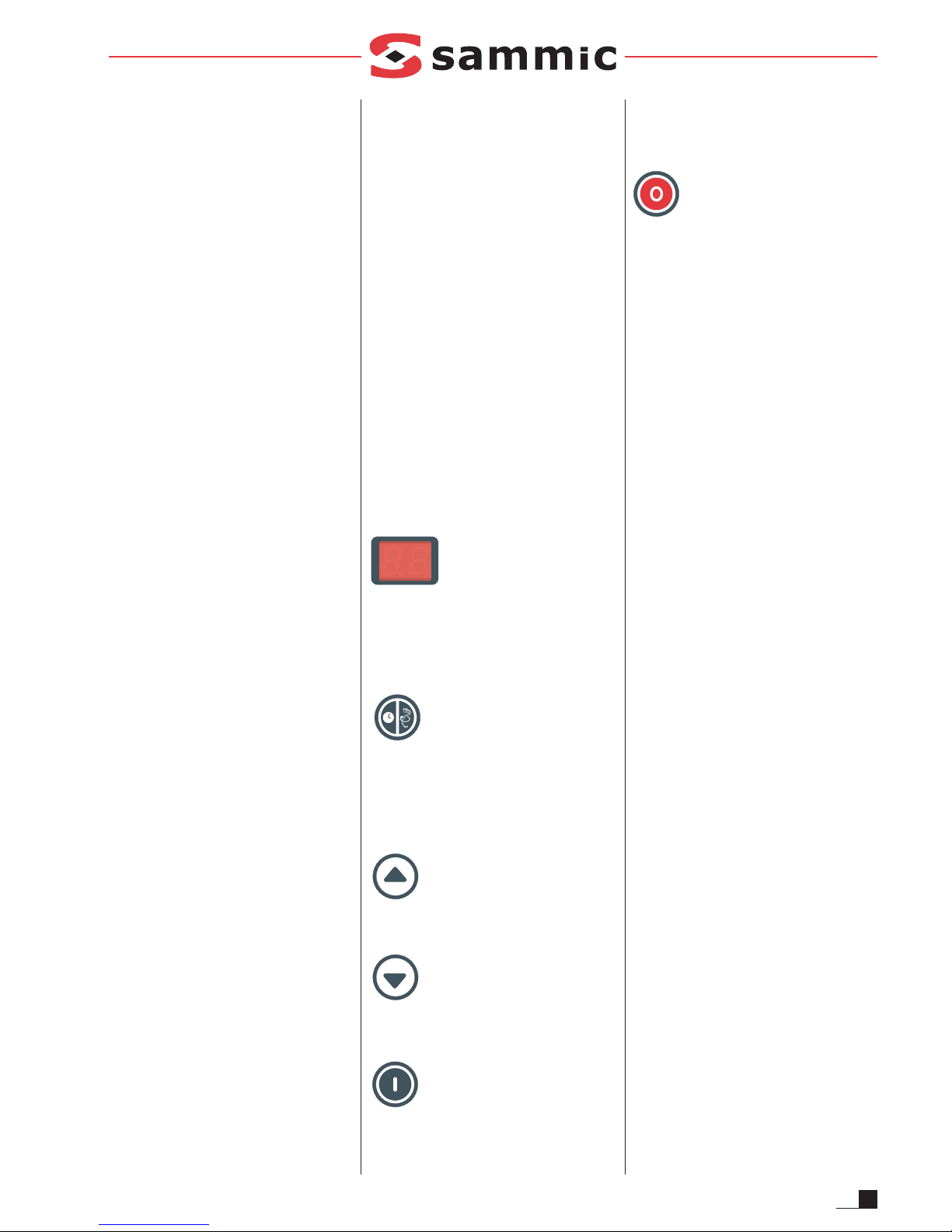
ELECTRONIC CONTROLLER FUNCTIONS
Figure 1: Display (L)
Displays the time in operation, speed and
various warnings. When you connect the
machine the display shows two horizontal lines
indicating standby, while the" time" (1) and
"speed" (2) LED's are off.
Figure 1: Function (A)
Press function to select the function to be
displayed - time or speed. Speed is selected if
pilot light (1) is on. Press "Function" (A) again to
see speed and pilot light (2) lights up. It can be
pressed with the motor on or off.
Figure 1: Up (H)
Each press increases the value selected on the
display.
Figure 1: Down (H)
Each press decreases the value selected on the
display or.
Figure 1: Start (B)
Starts the motor if the safety guard is closed and
the bowl in position. If either of the two safety
devices is missing when you press start, the
display shows "SE" (security) to show that a
safety device must be enabled for the machine
to start.
Figure 1: Stop (G)
The first press stops the motor and the display
starts flashing to show it is in standby mode. It
still stores the time and speed values. After 3
minutes, or when you press "stop" again, the
machine loses these values and returns to its
initial status. You will see 2 horizontal lines.
OPERATION
Time Control: Viewed when the "time" pilot light
(1) is on. It can be changed with the motor on or
off.
- Continuous operation: a rotating line on the
display shows that it has been selected.
- Timed operation: From 30 seconds to 30
minutes. Between 30 seconds and 10
minutes, select the time in 30-second
intervals. From 10 minutes onwards, select
the time in 1-minute intervals. The display
shows the countdown in the same way except
for the last minute, which counts down in
seconds (shown by the illuminated dot in the
bottom right hand corner of the display). When
the programmed time is completed, the
machine stops and a beep is heard.
Speed Control: Viewed with the "speed" pilot
light (2) on. You can choose from 1-10 different
speeds. When the motor is on, the speed is
displayed and automatically changes to show
the time after 5 seconds. The speed can be
changed when the motor is on or off.
Standby: Shown with 2 horizontal lines. Press
start for continuous operation at minimum
speed.
Energy-saving: If the machine is stopped for 5
minutes, the display switches off and only a dot
is shown. Press any key for the display to return.
START-UP
Before using the machine for the first time,
clean the area in contact with food with
(lukewarm) soapy water, rinse and leave to dry.
1. F
ITTING THE BOWL
- Place the bowl support at the lowest position.
- The bowl is attached to the support at three
points.
- Place the boiler so that the "MAX" label is visible.
Page 6

6
EN
- Ensure that touching surfaces are clean.
- Lift the bowl and pull outwards to remove it.
2. FITTING THE TOOLS
- Place the bowl support at the lowest position.
- Hook the tool on the tool holder.
- This is easier if the tool is fitted to the bowl
support previously.
3. SELECT THE TIME AND SPEED.
Adapt the speed and tool to the task being carried
out, remembering that available mixing strength
(torque) increases when the speed decreases.
4. OPERATION
The mixer only starts if the bowl is in the high
position with the label "MAX" on the front and
the safety guard in the down position. If any of
the safety devices is missing when you press
start, then the machine does not start and "SE"
is displayed.
5. MAXIMUM CAPACITIES
The working capacity of a mixer depends on:
- the tool used
- the nature, amount and density of the dough
- the correct speed.
Exceeding the maximum recommended
amounts adversely affects the operation and
life of the machine.
USING THE ACCESSORY HOLDER
1. You must unplug the machine from the
electricity supply.
2. Insert the accessory.
3. Rotate the accessory until it locks into the
shaft of the mixer and press fully down, lining
up the guide mark on the accessory with the
tab on the accessory holder.
4. Turn the handle on the side until the
accessory is firmly fixed.
5. Check that the safety devices of the mixer
are enables, meaning that the bowl support
is at the highest position and the protection
device lowered.
6. Complete the accessory if necessary
(screens, discs, etc.).
7. Plug the machine in to the electricity supply.
8. When you have finished, unplug the machine
again, remove the accessory and clean the
machine.
WARNING:
- Be careful when manipulating the
accessories as they are equipped with blades
and sharp elements.
- NEVER insert your hand nor any other utensil
through the inlet or outlet of the accessories, to
avoid accidents or deterioration of the same.
TOOL SPEED RANGE
CR-143 From 6 to 10, according to discs used
HM-71 From 1 to 5, according to type of meat
P-132 From 4 to 8
MAINTENANCE
WARNING: You must unplug the mixer from
the mains whenever cleaning, servicing or
repairing the mixer.
- The bowl and working tools are in contact with
the dough and must be cleaned immediately
after use, with hot water and a detergent
approved for use with foodstuffs. Then rinse
with copious hot water and disinfect using a
soft cloth soaked in ethyl alcohol (90º).
- DO NOT spray water on the outside of the
machine to clean it. Use a damp cloth and
any common detergent.
- Regularly check that the rear ventilation grilles
are not blocked.
- Dry the support guides and lubricate with
vaseline.
- The noise level of the machine in operation at a
height of 1.6 metres and 1 metre away, is less
than 75 dB(A). Background noise: 32 db(A).
OPERATING PROBLEMS:
- The electronic speed reducer is fitted with
devices to protect against current and voltage
fluctuations and overheating. When the
machine stops and "E1" appears on the
display, then a protective device has been
triggered. To disable this status, press "stop"
(G) or unplug the machine and wait.
- The bowl is in position and the safety guard
lowered. Press start and "SE" appears on the
display. A sensor is broken or loose.
- The planetary unit rotates in the wrong
direction. Reverse the phases at the speed
reducer outlet.
- If the power cable is worn, it should be
replaced by a technical service authorised by
SAMMIC S.L.
- The mixer has more torque when operating at
low speed. If you see the machine is jerking,
reduce the speed. If the problems persist,
stop the machine and check the amount and
quality of the dough or mixture.
EQUIPMENT
Standard
The standard equipment includes a stainless
steel bowl and three different tools:
1. Spiral kneading hook for all hard dough.
2. Beater spatula for soft confectionery dough.
3. Balloon whisk for all kinds of sauces.
Optional accessories: (See Page 14)
- 10-litre equipment for BE-20, BE-20 I and BE20 C mixers.
- 10-litre equipment for BE-30, BE-30 I and BE30 C mixers.
- 10-litre equipment for the BE-40 mixer.
- CR-143 Cutter/Grater, to cut vegetables and
grate bread, cheese, chocolate, etc.
- HM-71 Meat grinder, to grind all kinds of raw
and cooked meats.
- P-132 Masher, to turn all kinds of stews, soups
and sauces into purée.
IMPORTANT ADDITIONAL INFORMATION
This machine is not designed for use by
children or persons with physical, sensory or
mental disabilities, or by inexperienced or
unskilled persons, unless they have been
supervised or trained in using these machines
by a person responsible for their safety.
Page 7
LED Display ALM FLT Cause
Base Block
The software base block function is assigned to one of the digital inputs and the
input is off. The drive does not accept Run commands.
Control Fault
The torque limit was reached during deceleration for longer than 3 sec. when in
Open Loop Vector control
Ŗ The load inertia is too big.
Ŗ The torque limit is too low.
Ŗ The motor parameters are wrong.
Control
Circuit Fault
There is a problem in the drive’s control circuit.
Option
External
Fault
An external fault was tripped by the upper controller via an option card.
External
Fault
A forward and reverse command were input simultaneously for longer than 500
ms. This alarm stops a running motor.
External
Faults
Ŗ An external fault was triggered by an external device via one of the digital
inputs S1 to S6.
Ŗ The digital inputs are set up incorrectly.
Ground Fault
Ground leakage current has exceeded 50% of the drives rated output current.
Ŗ Cable or motor insulation is broken.
Ŗ Excessive stray capacitance at drive output.
Safe Disable
Both Safe Disable inputs are open. The drive output is safely disabled and the
motor can not be started.
to
to
Safe Disable
Faul t
Drive output is disabled while only one of the Safe Disable inputs is open. (normally both input signals H1 and H2 should be open)
Ŗ One channel is internally broken and does not switch off, even if the external
signal is removed.
Ŗ Only one channel is switched off by the upper controller.
Output
Phase Loss
Ŗ Output cable is disconnected or the motor winding is damaged.
Ŗ Loose wires at the drive output.
Ŗ Motor is too small (less than 5% of drive current).
Overcurrent
Ŗ Short circuit or ground fault on the drive output side
Ŗ The load is too heavy.
Ŗ The accel./decel. times are too short.
Ŗ Wrong motor data or V/f pattern settings.
Ŗ A magnetic contactor was switched at the output.
Heatsink
Overheat
Ŗ Surrounding temperature is too high.
Ŗ The cooling fan has stopped.
Ŗ The heatsink is dirty.
Ŗ The airflow to the heatsink is restricted.
Motor
Overload
Ŗ The motor load is too heavy.
Ŗ The motor is operated at low speed with heavy load.
Ŗ Cycle times of accel./ decel. are too short.
Ŗ Incorrect motor rated current has been set.
Drive
Overload
Ŗ The load is too heavy.
Ŗ The drive capacity is too small.
Ŗ Too much torque at low speed.
DC
Overvoltage
DC bus voltage rose too high.
Ŗ The deceleration time is too short.
Ŗ Stall prevention is disabled1.
Ŗ Braking chopper / resistor broken.
Ŗ Unstable motor control in OLV.
Ŗ Too high input voltage.
Input Phase
Loss
Ŗ Input voltage drop or phase imbalance.
Ŗ One of the input phase is lost.
Ŗ Loose wires at the drive input.
Braking
Transistor
Faul t
The internal braking transistor is broken.
Fault Reset
During Run
Fault reset was input when a run command was active.
DC
Undervoltage
The voltage in the DC bus fell below the undervoltage detection level (L2-05).
Ŗ The power supply failed or one input phase has been lost.
Ŗ The power supply is too weak.
or
Controller
Undervoltage
The drives controller power supply voltage is too low.
DC Charge
Circuit Fault
The charge circuit for the DC bus is broken.
7
EN
GENERAL FAULT AND ALARMS
Page 8
8
DE
ANGABEN FÜR DIE CE-MARKIERUNG
Jede Maschine ist mit folgenden Angaben versehen:
- Name und Anschrift des Herstellers: SAMMIC
S.L - Basarte 1 Azkoitia. Gipuzkoa (SPAIN)
- "CE" - Zeichen
- Das Modell der Maschine wird im folgenden
Abschnitt aufgeführt.
- Die Serien-Nr. erscheint auf dem Garantieschein
und auf der Konformitätserklärung.
MODELLE
Dieses Handbuch enthält Anleitungen für die
Aufstellung, den Betrieb und die Wartung der
Planeten-Rührmaschinen BE-10, BE-10C, BE20, BE-20C, BE-20I, BE-30, BE-30C, BE-30I,
BE-40 und BE-40C
Die Modell-Nummer und die Merkmale des
Gerätes sind auf dem Typenschild an der
Maschine aufgeführt.
Diese Rührmaschinen sind gemäss den
nachstehenden Europäischen Richtlinien und
Normen entworfen und hergestellt worden:
Maschinenrichtlinie 98/37/CEE
Niederspannungsrichtlinie 73/23/CEE
Richtlinie für Elektromagnetische Verträglichkeit
89/336/CEE
Norm EN-454: Planeten-Rührmaschinen. Sicherheitsund Hygieneanforderungen.
Schutzarten gemäss der Norm EN 60529
IP Maschine IP Schalter
BE-10 / BE-10C 21 55
BE-20 / BE-20C / BE-20I 23 55
BE-30 / BE-30C / BE-30I 23 55
BE-40 / BE-40C 23 55
AUFSTELLUNG
Zur Erzielung bester Leistungen und für eine
optimale Instandhaltung der Maschine sollten
die in diesem Handbuch enthaltenen
Anleitungen genau befolgt werden.
S
TANDORT
Benutzen Sie die drei verstellbaren Schraubfüsse,
um die Maschine gut auszunivellieren, damit auch
bei maximaler Geschwindigkeit ihre Stabilität
gewährleistet ist.
ELEKTRISCHER ANSCHLUSS
1. Merkmale.
- Die Rührmaschine ist für Einphasenspannung
230V 50-60 Hz vorgesehen.
- Sämtliche Modelle sind mit einem
Drehstrommotor bestückt, der von einem
Frequenzwandler geregelt wird.
- Auf keinen Fall muss die Konfiguration der
Frequenzwandler geändert werden.
- ERDANSCHLUSS IST PFLICHT. Der
Frequenzwandler besitzt einen Filter, der die
vorhandenen Störungen an die Erde ableitet.
Es kann deshalb vorkommen, dass der
Differentialschalter auf unangebrachte Weise
agiert. Es empfiehlt sich deshalb, für die
Maschine einen eigenen Differentialschalter
oder sonst einen "hoch immunizierten"
Differentialschalter zu verwenden.
- Benötigt wird eine Wandsteckdose mit
Differential- und Thermomagnetschutz 2P für
20A mit dem entsprechenden Stecker. Der
Schalter oder Stecker muss gut zugänglich
sein, um die Maschine abschalten zu können.
2. Kabelmerkmale:
Die SAMMIC Rührmaschinen werden mit
einem 1,5 m langen thermoplastbeschichte-ten
Kabel geliefert.
DER ERDANSCHLUSS IST PFLICHT. Der
Erdungsdraht der Maschine ist
gekennzeichnet.
FUNKTIONEN DER ELEKTRONISCHEN
STEUERUNG
Bild 1 Anzeige (L)
Visualisiert die Betriebszeit, die
Geschwindigkeit und die verschiedenen
Warnungen. Bei Einschalten der Maschine
erscheinen auf der Anzeige zwei waagerechte
Wartelinien und die LEDs für "Zeit" (1) und
"Geschwindigkeit" (2) sind verloschen.
Bild 1 Funktion (A)
Mit einem Druck wählen wir die anzuzeigende
Funktion, die Zeit oder die Geschwindigkeit.
Wenn die Kontrolllampe (1) aufleuchtet, haben
wir die Zeit angewählt. Wenn wir erneut auf
"Funktion" (A) drücken, sehen wir die
Geschwindigkeit und die Kontrolllampe (2)
leuchtet auf. Man kann diese Taste bei
laufendem oder stehendem Motor betätigen.
Bild 1 Erhöhen (H)
Mit jedem Druck erhöhen wir den auf der
Anzeige angewählten Wert.
Bild 1 Verringern (H)
Mit jedem Druck verringern wir den auf der
Anzeige angewählten Wert.
Bild 1 Lauf (B)
Diese Taste setzt den Motor in Gang, immer
wenn der Rost geschlossen und der Kessel in
seiner richtigen Stellung ist. Wenn eine der
Sicherheitsvorkehrungen fehlt und wir auf Lauf
drücken, so erscheint auf der Anzeige "SE"
(Sicherheit) was bedeutet, dass für den Start
noch irgendeine Sicherung fehlt.
Bild 1 Stopp (G)
Ein Druck auf diese Taste bringt den Motor zum
Stillstand, die Anzeige beginnt zu blinken und
gibt damit zu verstehen, dass sie in
Wartestellung ist. Die Werte für Zeit und
Geschwindigkeit bleiben bewahrt. Wenn man 3
Minuten verstreichen lässt oder wenn man
erneut auf "Stop" drückt, gehen diese Werte
verloren und die Maschine kehrt in ihren
Ausgangszustand zurück. Auf der Anzeige
sehen wir nun zwei waagerechte Linien.
B
ETRIEBSWEISE
Zeitkontrolle: Erscheint, wenn die Kontrolllampe
"Zeit" (1) leuchtet. Änderungen sind bei
laufendem sowie bei stillstehendem Motor
möglich.
- Dauerbetrieb: Ein drehender Strich auf der
Anzeige bestätigt diese Wahl.
- Zeitgesteuerter Betrieb: Von ½ Minute bis 30
Minuten. Von ½ bis 10 Minuten wird die Zeit in
Stufen von je ½ Minute gewählt. Ab 10
Minuten wird die Zeit in Minuten gezählt. Das
Abwärtszählen erscheint auch in dieser Weise
auf der Anzeige, mit Ausnahme der letzten
Minute, die in Sekunden zählt (angezeigt
durch Aufleuchten eines Punktes rechts unten
auf der Anzeige). Bei Ablauf der
einprogrammierten Zeit bleibt die Maschine
stehen und es ertönt ein Piepton.
Geschwindigkeitskontrolle: Diese wird
angezeigt, wenn die Kontrolllampe
"Geschwindigkeit" (2) leuchtet. Es können 10
verschiedene Geschwindigkeiten gewählt
werden. Bei laufendem Motor wird die
Geschwindigkeit angezeigt, nach 5 Sekunden
geht die Anzeige automatisch auf Angabe der
Zeit über. Änderungen sind bei laufendem
sowie bei stillstehendem Motor möglich.
Warten: Wird mit zwei waagerechten Linien
angezeigt. Wenn wir auf "Lauf" drücken,
erhalten wir Dauerbetrieb und
Mindestgeschwindigkeit.
Sparen: Wenn wir bei stillstehender Maschine 5
Minuten lang nichts an der Anzeige
unternehmen, so wird diese dunkel und zeigt
nur noch einen Punkt. Ein Druck auf eine
beliebige Taste schaltet die Anzeige wieder ein.
Page 9

9
DE
INBETRIEBNAHME
Vor der Erstinbetriebnahme der Maschine den
Bereich, der in Kontakt mit Lebensmitteln
kommt, mit Seifenlauge (lauwarm) reinigen,
abspülen und trocknen lassen.
1. ANBRINGEN DES KESSELS
- Bringen Sie den Kesselhalter in seine unterste
Position.
- Der Kessel passt sich an drei
Befestigungspunkten an den Kesselhalter an.
- Beim Aufstellen des Kessels ist darauf zu achten,
dass der Aufkleber “MAX” gut sichtbar ist.
- Sorgen Sie dafür, dass alle Teile, die mit den
Nahrungsmitteln in Berührung kommen,
einwandfrei sauber sind.
- Zum Herausnehmen des Kessels wird dieser
angehoben und nach aussen herausgezogen.
2. ANBRINGEN DER RÜHRUTENSILIEN
- Den Kesselhalter in die untere Stellung bringen.
- Die Achse des Rührwerkzeugs in die
Werkzeugaufnahme der Maschine stecken.
- Um das Manipulieren zu erleichtern empfiehlt
es sich, das Rührwerkzeug zuerst in den
Kessel zu legen.
3. ZEIT UND GESCHWINDIGKEIT ANWÄHLEN.
Geschwindigkeit und Rührwerkzeug müssen
für die zu leistende Arbeit geeignet sein und
entsprechend angepasst werden. Beachten
Sie, dass die Mitnahmekraft (Moment) des
Werkzeugs bei Verringern der Geschwindigkeit
grösser wird.
4. BETRIEBSWEISE
Die Rührmaschine setzt sich nur in Gang, wenn der
Kessel Der Kessel ist in der oberen Position mit dem
"MAX" Etikett auf der Vorderseite und der
Sicherheitsrost heruntergeklappt ist. Wenn bei
Betätigen der "Lauf"-Taste eine der
Sicherheitsvorkehrungen fehlt, setzt die Maschine
sich nicht in Gang und es erscheint der Hinweis "SE".
5. MAXIMALE LEISTUNGEN
Die Arbeitsleistung einer Rührmaschine ist
abhängig von:
- dem verwendeten Rührwerkzeug,
- der Art, der Menge und der Dichte des
Rührgutes
- der geeigneten Geschwindigkeit.
Das Überschreiten der empfohlenen
Höchstmengen hat negative Auswirkungen auf
die Arbeit und die Lebensdauer der Maschine.
BETRIEBSWEISE DER WERKZEUGAUFNAHME
1. Die Maschine muss von der Stromleitung
getrennt werden.
2. Das Rührwerkzeug einstecken.
3. Drehen Sie das Rührwerkzeug bis es in der
Achse der Rührmaschine einrastet und
stecken Sie es bis zum Anschlag ein, indem
Sie die Werkzeugführung mit der
Aussparung an der Werkzeugaufnahme
zusammentreffen lassen.
4. Den seitlichen Knopf drehen, bis das
Rührwerkzeug einwandfrei befestigt ist.
5. Nachprüfen, ob die Sicherheitsmassnahmen
getroffen sind, d.h. der Kessel muss in der
oberen Stellung und die Schutzvorrichtung
heruntergelassen sein.
6. Falls erforderlich, Zubehörteile
vervollständigen (Roste, Scheiben...).
7. Die Maschine einschalten
8. Bei Arbeitsende muss die Maschine von der
Stromleitung getrennt, das Zubehör abmontiert
und die Maschine gereinigt werden.
ACHTUNG:
- Mit dem Zubehör vorsichtig umgehen, da
es mit Schneidemessern und scharfen
Schneideelemente ausgestattet ist.
- NIEMALS die Hand in die Ausgangs- bzw.
Eingangsöffnung der Zubehörteile
stecken, um Verletzungen und eine
Beschädigung derselben zu vermeiden.
WERKZEUG GESCHWINDIGKEITSBEREICH
CR-143 Von 6 bis 10, je nach den Scheiben
HM-71 Von 1 bis 5 je nach Fleischart
P-132 Von 4 bis 8
WARTUNG
ACHTUNG: Vor jedem Eingriff in die Maschine
zwecks Reinigung, Überprüfung oder
Reparatur, muss die Rührmaschine unbedingt
von der Netzleitung getrennt werden.
- Kessel und Werkzeuge kommen mit dem
Rührgut in Berührung und müssen deshalb
sofort nach Gebrauch mit heissem Wasser und
einem für Lebensmittelkontakt zugelassenen
Spülmittel gereinigt werden. Abschliessend
gründlich mit reichlich heissem Wasser
klarspülen und mit einem mit Ethylalkohol (90º)
getränkten weichen Tuch desinfizieren
- Die Maschine darf von aussen NICHT
direkt mit einem Wasserstrahl abgespritzt
werden. Verwenden Sie zum Reinigen ein
weiches Tuch und ein beliebiges übliches
Putzmittel.
- Prüfen Sie regelmässig nach, ob die Lüftungsrillen
auf der Rückseite nicht verstopft sind.
- Die Führungen des Kesselhalters müssen
abgetrocknet und mit Vaseline eingefettet werden.
- Der Geräuschpegel der in Betrieb befindlichen
Maschine, gemessen in 1,6 m Höhe und 1 m
Abstand, beträgt weniger als 75 dB(A).
Grundgeräusch: 32 db(A).
BETRIEBSSTÖRUNGEN:
- Der elektronische Geschwindigkeitsregler
verfügt über Schutzvorrichtungen gegen
Spannungs- und Stromschwankungen oder
gegen übermässige Erwärmung. Wenn die
Maschine stehenbleibt und auf der Anzeige
"E1" erscheint, bedeutet dies, dass eine der
Schutzvorrichtungen gewirkt hat. Um diesen
Zustand zu überholen, bitte auf "Stopp" (G)
drücken oder die Maschine von der
Netzleitung trennen und warten.
- Der Kessel ist in seiner korrekten Position und
der Schutzrost ist heruntergelassen. Bei Druck
auf "Lauf" erscheint "SE" auf der Anzeige. Ein
Detektor ist gestört oder hat sich gelöst.
- Die Planetendrehrichtung ist falsch. Die
Phasen des Motors am Ausgang des
Frequenzwandlers umtauschen.
- Wenn das Zuleitungskabel beschädigt ist, muss
es bei einer von SAMMIC S.L. zugelassenen
Technischen Dienststelle ausgetauscht werden.
- Das Kräftepaar der Rührmaschine ist grösser,
wenn sie bei niedriger Geschwindigkeit arbeitet.
Wenn die Maschine Schwierigkeiten hat und
Abbremsungen beobachtet werden, so sollte
man die Geschwindigkeit verringern. Wenn das
Problem fortbesteht, bitte die Maschine
anhalten und die Menge oder Qualität der
Rührmasse oder -mischung nachprüfen.
AUSRÜSTUNG
Standard
Die Standard-Ausrüstung umfasst einen Kessel
aus rostfreiem Stahl und drei verschiedene
Rührwerkzeuge:
1. Spiralförmiger Knethaken für alle festen
Massen und Teige.
2. Flachrührer für weiche Konditoreimassen.
3. Rührbesen für alle Arten von Emulsionen.
Optionales Zubehör: (Siehe Seite.14)
- 10-Liter-Garnitur für Rührmaschinen BE-20,
BE-20 I y BE-20 C.
- 10-Liter-Garnitur für Rührmaschinen BE-30,
BE-30 I y BE-30 C.
- 20-Liter-Garnitur für Rührmaschine BE-40.
- Schneid- und Reibgerät CR-143, zum
Schneiden von Gemüse und Reiben von Brot,
Käse, Schokolade usw.
- Fleischwolf HM-71, für alle Arten von rohem
und gekochtem Fleisch.
- Pürierer P-132, zum Pürieren aller Arten von
Eintopfgerichten und Sossen.
ANDERE WICHTIGE BEMERKUNGEN
Diese Anlage ist nicht für die Verwendung durch
Kinder oder Personen bestimmt, deren körperliche,
sensorische oder geistige Fähigkeiten beeinträchtigt
sind oder die nicht über die nötige Erfahrung oder
das Wissen verfügen, mit Ausnahme solcher
Personen, die entsprechend durch eine für ihre
Sicherheit verantwortliche Person bei der
Verwendung der Anlage beaufsichtigt oder über
Page 10

DE
10
LED-Anzeige ALM FLT Ursache
Endstufensperre
Die Software-Endstufensperrfunktion ist einem der digitalen Eingänge zugeordnet, und der Eingang ist aktiv. Der Antrieb nimmt keinen START-Befehl an.
Regelungsfehler
Bei Vektorregelung ohne Rückführung wurde für die Dauer von mindestens
drei Sekunden ein Drehmomentgrenzwert während der Verzögerung erreicht.
Ŗ Die Massenträgheit der Last ist zu groß.
Ŗ Der Drehmomentgrenzwert ist zu niedrig.
Ŗ Die Motorparameter sind falsch.
Steuerkreisfehler
Es gibt ein Problem im Steuerkreis des Antriebs.
Option Externer
Fehler
Über eine Optionskarte wurde ein externer Fehler durch die übergeordnete
Steuerung ausgelöst.
Externer Fehler
Ein Vorwärts- und Rückwärtsbefehl wurden für 500 s oder länger gleichzeitig
eingegeben. Durch diesen Alarm wird der Motorlauf gestoppt.
Externe Fehler
Ŗ Über einen der Digitaleingänge S1 bis S6 wurde von einem externen Gerät
ein externer Fehler ausgelöst.
Ŗ Die Digitaleingänge sind falsch eingestellt.
Erdschlussfehler
Der Erdschlussstrom hat 50 % des Antriebs-Nennausgangsstroms überschritten.
Ŗ Die Kabel-oder Motorisolierung ist defekt.
Ŗ Übermäßige Streukapazität am Antriebsausgang.
Sicherer Halt
aktiv (H1, H2)
Beide Eingänge zum sicheren Halt sind geöffnet. Der Ausgang des Antriebs
wird mit dem sicheren Halt ausgeschaltet, und der Motor kann nicht gestartet
werden.
bis
bis
Fehler sicherer
Halt
Der Ausgang des Antriebs wird deaktiviert, wobei nur einer der Eingänge zum
sicheren Halt geöffnet ist. (Normalerweise sollten die Eingangssignale H1 und
H2 beide geöffnet sein.)
Ŗ Ein Kanal hat einen internen Defekt und schaltet nicht aus, auch wenn das
externe Signal unterbrochen wird.
Ŗ Nur ein Kanal wird durch den übergeordneten Controller ausgeschaltet.
Ausgangsphase
nausfall
Ŗ Das Ausgangskabel hat sich gelöst, oder die Motorwicklung ist beschädigt.
Ŗ Lose Drähte am Antriebsausgang.
Ŗ Der Motor ist zu klein (unter 5 % des Antriebsstroms).
Überstrom
Ŗ Kurzschluss oder Erdschlussfehler an der Antriebs-Ausgangsseite.
Ŗ Die Last ist zu groß.
Ŗ Die Beschleunigungs-/Verzögerungszeiten sind zu kurz.
Ŗ Die Motordaten oder die U/f-Kennlinieneinstellungen sind falsch.
Ŗ Ein Netzschütz wurde am Ausgang geschaltet.
Überhitzung des
Kühlkörpers
Ŗ Die Umgebungstemperatur ist zu hoch.
Ŗ Der Lüfter läuft nicht mehr.
Ŗ Der Kühlkörper ist verschmutzt.
Ŗ Der Luftstrom zum Kühlkörper ist zu gering.
Motorüberlast
Ŗ Die Motorlast ist zu groß.
Ŗ Der Motor wird bei niedriger Drehzahl mit hoher Last betrieben.
Ŗ Die Zykluszeiten für die Beschleunigung/Verzögerung sind zu kurz.
Ŗ Die Einstellung des Motornennstroms ist nicht korrekt.
Antriebsüberlast
Ŗ Die Last ist zu groß.
Ŗ Die Antriebsleistung ist zu gering.
Ŗ Zu hohes Drehmoment bei niedriger Drehzahl.
DC-
Überspannung
Die Zwischenkreisspannung ist zu hoch angestiegen.
Ŗ Die Verzögerungszeit ist zu kurz.
Ŗ Der Blockierschutz ist deaktiviert.
Ŗ Der Bremstransistor/-widerstand ist defekt.
Ŗ Instabile Motorsteuerung bei OLV.
Ŗ Zu hohe Eingangsspannung.
Eingangsphasen
ausfall
Ŗ Abfall der Eingangspannung oder Phasen-Unsymmetrie.
Ŗ Ausfall einer der Eingangsphasen.
Ŗ Lose Drähte am Antriebseingang.
Bremstransistorf
ehler
Der interne Bremstransistor ist defekt.
Fehlerrücksetzung
während des
Betriebs.
Eine Fehlerrücksetzung wurde bei aktiviertem START-Befehl eingegeben.
DC-
Unterspannung
Die Zwischenkreisspannung lag unterhalb der Einstellung für Unterspannungserkennung (L2-05).
Ŗ Ausfall der Spannungsversorgung oder Ausfall einer Eingangsphase.
Ŗ Die Versorgungsspannung ist zu niedrig.
oder
Controller-
Unterspannung
Die Versorgungsspannung des Antriebs-Controllers ist zu niedrig.
DC-
Ladekreisfehler
Der Ladekreis für den Zwischenkreis ist unterbrochen.
ALLGEMEINE FEHLER UND ALARME
Page 11

11
FR
INDICATIONS POUR LE MARQUAGE CE
Chaque machine est identifiée par les
indications suivantes :
- Le nom et l'adresse du fabricant : SAMMIC
S.L - Basarte 1 Azkoitia. Gipuzkoa
(ESPAGNE).
- Le marquage "CE ".
- Le modèle de machine, comme indiqué au
paragraphe suivant.
- Le numéro de série qui est indiqué sur le bon
de garantie et sur la déclaration de conformité.
MODÈLES
La présente notice décrit l'installation, le
fonctionnement et l'entretien des batteurs
planétaires BE-10, BE-10C, BE-20, BE-20C, BE20I, BE-30, BE-30C, BE-30I, BE-40 et BE-40C.
La référence et les caractéristiques du modèle
sont indiquées sur la plaque signalétique
apposée sur la machine.
Ces batteurs sont conçus et fabriqués
conformément aux Directives et Normes
européennes suivantes :
Directive Machines 98/37/CEE
Directive Basse Tension 73/23/CEE
Directive Compatibilité électromagnétique
89/336/CEE
Norme EN-454 : Batteurs Planétaires.
Prescriptions de sécurité et d'hygiène.
Indices de protection suivant la norme EN
60529
IP Machine IP Commandes
BE-10 / BE-10C 21 55
BE-20 / BE-20C / BE-20I 23 55
BE-30 / BE-30C / BE-30I 23 55
BE-40 / BE-40C 23 55
INSTALLATION
Afin d'obtenir les performances optimales et
assurer une bonne conservation de la machine,
il est important de suivre attentivement les
instructions contenues dans cette notice.
EMPLACEMENT
Visser et dévisser les trois pieds réglables pour
mettre de niveau la machine et assurer une
bonne stabilité à la vitesse maximale.
RACCORDEMENT ÉLECTRIQUE
1. Caractéristiques.
- Le batteur est prévu pour fonctionner sur
tension de 230V 50-60 Hz monophasée.
- Le moteur est triphasé sur tous les modèles. Il
est commandé par un variateur de fréquence.
- Surtout ne jamais manipuler la
configuration du variateur.
- LA MISE A LA TERRE EST OBLIGATOIRE.
Le variateur est équipé d'un filtre qui évacue
vers la terre les perturbations existantes. Il
peut donc arriver que le disjoncteur différentiel
de l'installation déclenche intempestivement. Il
est recommandé d'utiliser un disjoncteur
différentiel propre à la machine ou un modèle
du type "super immunisé".
- Prévoir une prise de courant murale avec
protection différentielle et magnétothermique 2P
calibre 20A, avec sa fiche correspondante.
S'assurer de l'accessibilité de l'interrupteur ou de
la fiche pour le débranchement de la machine.
2. Caractéristiques du cordon d'alimentation
Les batteurs SAMMIC sont fournis avec un
cordon d'alimentation de 1,5 m de longueur à
gainage thermoplastique.
LA MISE A LA TERRE EST OBLIGATOIRE. Le
fil de terre de la machine est repéré.
FONCTIONS DE LA COMMANDE
ÉLECTRONIQUE
Dessin 1 Ecran d'affichage (L)
Il affiche le temps de fonctionnement, la vitesse
et différents avertissements. A la mise sous
tension de la machine, deux raies horizontales
d'attente apparaissent sur l'écran et les voyants
led "temps" (1) et "vitesse" (2) sont éteints.
Dessin 1 Fonction (A)
La pression sur ce bouton permet de
sélectionner la fonction à afficher : "temps" ou
"vitesse". Le voyant (1) est allumé lorsque la
fonction "temps" est sélectionnée. Une nouvelle
pression sur "Fonction" (A) fait passer
l'affichage sur "vitesse" et le voyant (2)
s'allume. Le bouton peut être actionné quand le
moteur est en marche ou arrêté.
Dessin 1 Monter (H)
Chaque pression sur la touche incrémente la
valeur sélectionnée sur l'écran.
Dessin 1 Descendre (H)
Chaque pression sur la touche décrémente la
valeur sélectionnée sur l'écran.
Dessin 1 Marche (B)
Le moteur ne peut démarrer que si la grille est
fermée et la cuve est en place. Si l'une des
deux sécurités manque, l'écran affiche "SE"
(sécurité) pour indiquer que l'une des sécurités
manque pour permettre le démarrage.
Dessin 1 Arrêt (G)
Une première pression sur ce bouton arrête le
moteur. L'écran clignote pour indiquer qu'il est en
état d'attente. Les valeurs de "temps" et de
"vitesse" sont conservées. Au bout de 3 minutes
ou en cas de nouvelle pression sur "Arrêt", ces
valeurs sont perdues et la machine revient à l'état
initial. L'écran montre deux raies horizontales.
FONCTIONNEMENT
Fonction Temps : Elle est affichée lorsque le
voyant "temps" (1) est allumé. Le temps peut
être modifié avec le moteur en marche ou arrêté.
- Marche continue : une raie tournant sur l'écran
indique que ce mode est sélectionné.
- Marche temporisée : Minuterie de ½ minute à
30 minutes. Entre ½ et 10 minutes, le temps
peut être sélectionné de ½ minute en ½ minute.
Au-delà de 10 min., il l'est en minutes. L'écran
affiche le décompte de la même manière, sauf
la dernière minute qui est décomptée en
secondes (un point s'allume alors dans la partie
inférieure droite de l'affichage pour l'indiquer).
Lorsque le temps programmé est écoulé, la
machine s'arrête et émet un signal sonore.
Fonction Vitesse : Elle est affichée lorsque le
voyant "vitesse" (2) est allumé. Le choix des
vitesses est possible de 1 à 10. Lorsque le
moteur est en marche, l'écran affiche la vitesse,
puis au bout de 5 s. il passe automatiquement
sur "temps". La vitesse peut être modifiée avec
le moteur en marche ou arrêté.
Attente : Deux raies horizontales apparaissent sur
l'écran. Si on appuie sur "Marche", la machine
démarre en marche continue et en petite vitesse.
Economie d'énergie : Si, la machine étant
arrêtée, aucune action n'est faite pendant 5
minutes, l'écran s'éteint et ne laisse voir qu'un
point. Il se rallume lorsqu'on appuie sur
n'importe quelle touche.
Page 12

12
FR
MISE EN MARCHE
Avant d'utiliser la machine pour la première fois,
nettoyez la zone de contact avec les aliments
avec de l'eau savonneuse (tiède), rincez et
laissez-la sécher.
1. MISE EN PLACE DE LA CUVE
- Mettre le support de cuve en position basse.
- La cuve est verrouillée sur le support par trois
points de fixation.
- Placez la chaudière de sorte que l'étiquette
"MAX" soit bien visible.
- S'assurer que les surfaces en contact sont
propres.
- Pour enlever la cuve, la lever et tirer vers
l'extérieur.
2. MONTAGE DES OUTILS
- Mettre le support de cuve en position basse.
- Engager l'axe de l'outil dans le porte-outil.
- Pour faciliter cette opération, mettre d'abord
l'outil dans la cuve.
3. SÉLECTIONNER LE TEMPS ET LA VITESSE.
Adapter la vitesse et l'outil en fonction du travail
à réaliser, en tenant compte que la puissance
d'entraînement disponible (couple) augmente
lorsqu'on diminue la vitesse.
4. FONCTIONNEMENT
La mise en marche du batteur n'est possible
que si la cuve est en position haute avec
l’étiquette “MAX” en face et la grille de sécurité
est abaissée. Si l'une de ces sécurités manque,
le batteur ne se met pas en marche lorsqu'on
appuie sur le bouton de marche et l'écran
affiche "SE".
5. CAPACITÉS MAXIMALES
La capacité de travail d'un batteur est fonction de:
- l'outil utilisé,
- la nature, la quantité et la densité de la pâte,
et
- la vitesse appropriée.
Le dépassement des quantités maximales
préconisées va au détriment de la qualité du
travail et de la durée de vie de la machine.
FONCTIONNEMENT DE LA PRISE
D'ACCESSOIRES
1. Il est impératif de débrancher la machine
du secteur.
2. Engager l'accessoire.
3. Faire pivoter l'accessoire pour l'emboîter
dans l'arbre d'entraînement du batteur et le
rentrer à fond, en mettant en concordance le
guide de l'accessoire et l'encoche de la prise
d'accessoires.
4. Tourner la manette latérale pour bloquer
parfaitement l'accessoire.
5. Vérifier que les sécurités du batteur sont
activées, c'est-à-dire que la cuve est dans sa
position la plus haute et que la grille de
protection est descendue.
6. Compléter l'accessoire si nécessaire (grilles,
disques, etc.).
7. Brancher la machine.
8. A la fin du travail, débrancher de nouveau le
batteur du secteur, démonter l'accessoire et
nettoyer la machine.
ATTENTION :
- Faites attention lors de la manipulation
d'accessoires ; ils sont équipés de lames
et d'éléments coupants.
- N'introduisez JAMAIS la main ni un ustensile
quelconque par les orifices de sortie ou
d'entrée des accessoires, pour éviter toute
blessure ou tout dommage sur le matériel.
OUTIL PLAGE DE VITESSE
CR-143 Position 6 à 10 suivant disques
HM-71 Position 1 à 5 suivant type de viande
P-132 Position 4 à 8
ENTRETIEN
ATTENTION: Avant toute intervention pour
le nettoyage, la révision ou la réparation du
batteur, il est impératif de débrancher le
batteur du secteur.
- La cuve et les outils de travail étant en contact
avec la pâte, ils doivent être immédiatement
lavés après leur utilisation, avec de l'eau
chaude et un détergent agréé pour usage
alimentaire. Les rincer abondamment à l'eau
chaude et les désinfecter avec un chiffon doux
imbibé d'alcool éthylique (90º).
- La carrosserie de la machine NE DOIT PAS
être nettoyée au jet d'eau. La nettoyer à
l'aide d'une éponge humide et d'un détergent
courant.
- Vérifier régulièrement que les grilles
d'aération à l'arrière de l'appareil ne sont pas
obstruées.
- Essuyer et graisser légèrement avec de la
vaseline les guides du support.
- Le niveau de bruit de la machine, en marche,
mesuré à 1,6 m de hauteur et 1 m de distance,
est inférieur à 75 dB (A). Bruit de fond : 32 dB (A).
INCIDENTS DE FONCTIONNEMENT
- Le variateur de vitesse électronique est protégé
contre les fluctuations de tension et d'intensité
ou les surchauffes. Si la machine s'arrête et que
l'écran affiche "E1", c'est qu'une des protections
est déclenchée. Pour pouvoir redémarrer,
appuyer sur "Arrêt " (G) ou débrancher la
machine du secteur et attendre.
- La cuve est en position et la grille est
descendue. Lorsqu'on appuie sur "Marche",
l'écran affiche "SE". Un des détecteurs est
endommagé ou desserré.
- Le sens de rotation du planétaire n'est pas le
correct. Inverser les phases du moteur à la
sortie du variateur.
- En cas d'endommagement du cordon
d'alimentation, son remplacement doit être
impérativement effectué par un service
technique agréé par SAMMIC S.L.
- Le batteur a un couple plus élevé lorsqu'il
fonctionne en petite vitesse. Si on constate que
la machine peine ou manque de puissance,
réduire la vitesse. Si les problèmes persistent,
arrêter la machine et réviser la quantité ou la
consistance de la pâte ou du mélange.
EQUIPEMENT
Standard
L'équipement standard comprend une cuve
inox et trois outils différents :
1. Crochet pétrisseur spirale, pour toutes les
pâtes dures.
2. Palette mélangeuse, pour les pâtes molles
de pâtisserie.
3. Fouet, pour tous types d'émulsions.
Accessoires en option : (voir page 14)
- Equipement de 10 litres pour les batteurs BE20, BE-20 I et BE-20 C.
- Equipement de 10 litres pour les batteurs BE30, BE-30 I et BE-30 C.
- Equipement de 20 litres pour le batteur BE-40.
- Coupe-légumes CR-143, pour couper les
légumes et râper pain, fromage, chocolat, etc.
- Hachoir à viande HM-71, pour hacher toutes
sortes de viandes crues et cuites.
- Presse-purée P-132, pour passer tous types
de purées, soupes et sauces.
AUTRES OBSERVATIONS IMPORTANTES
Cet appareil n’a pas été conçu pour être utilisé
par des enfants ou des personnes avec des
capacités physiques sensorielles ou mentales
réduites ou qui n’ont pas l’expérience ou les
connaissances nécessaires, sauf si elles ont
reçu une formation ou des instructions relatives
à l’utilisation de l’appareil par une personne
responsable de sa sécurité.
Page 13

Achage LED ALM FLT Cause
Bloc de base
La fonction de bloc de base logicielle est attribuée à l’une des entrées numériques et l’entrée passe sur OFF. Le variateur n’accepte pas les commandes Run.
Erreur
de contrôle
La limite du couple a été atteinte pendant une décélération de plus de 3 secondes en cas de contrôle vectoriel en boucle ouverte.
Ŗ L’inertie de charge est trop importante.
Ŗ La limite de couple est insuffisante.
Ŗ Les paramètres moteur sont faux.
Erreur
de circuit
de contrôle
Il y a un problème dans le circuit de contrôle du variateur.
Erreur externe
option
Une erreur externe a été déclenchée par le contrôleur supérieur via la carte
optionnelle.
Erreur externe
Les commandes de fonctionnement en marche avant / arrière ont été saisies
simultanément pendant plus de 500 ms. Cette alarme interrompt le fonctionnement d’un moteur.
Erreurs
exter nes
Ŗ Une erreur externe a été déclenchée par un périphérique via une des entrées
numériques S1 à S6.
Ŗ Les entrées numériques sont mal configurées.
Erreur
de masse
Le courant de fuite de masse a dépassé 50 % du courant de sortie nominal
du variateur.
Ŗ L’isolation du câble ou du moteur est coupée.
Ŗ Capacité de parasitage excessive au niveau de la sortie du variateur.
Désactivation
de sécurité
Les deux entrées de désactivation de sécurité sont ouvertes. La sortie
du variateur est désactivée de manière sûre et il n’est pas possible de démarrer le moteur.
à
à
Erreur de
désactivation
de sécurité
La sortie du variateur est désactivée alors que seule une des 2 entrées
de désactivation de sécurité est ouverte (les deux signaux d’entrée H1 et H2
doivent normalement être ouverts).
Ŗ Un canal est coupé au niveau interne et ne se coupe pas, même si le signal
externe est supprimé.
Ŗ Un seul canal est coupé par le contrôleur supérieur.
Perte de phase
de sortie
Ŗ Le câble de sortie est déconnecté ou la bobine du moteur est endommagée.
Ŗ Câbles desserrés au niveau de la sortie du variateur.
Ŗ Moteur trop petit (moins de 5 % du courant du variateur)
Surintensité
Ŗ Erreur de masse ou court-circuit côté sortie du variateur
Ŗ La charge est trop lourde.
Ŗ Les temps d’accél. / décél. sont trop courts.
Ŗ Données moteur ou paramètres de schéma V/f erronés
Ŗ Un contacteur magnétique a été commuté au niveau de la sortie.
Surchauffe
du radiateur
Ŗ La température ambiante est trop élevée.
Ŗ Le ventilateur s'est arrêté.
Ŗ Le radiateur est sale.
Ŗ Le flux d’air vers le radiateur est réduit.
Surcharge
du moteur
Ŗ La charge du moteur est trop lourde.
Ŗ Le moteur tourne à vitesse faible avec une charge élevée.
Ŗ Les temps de cycle d’accél. / de décél. sont trop courts.
Ŗ Le courant nominal du moteur est incorrect.
Surcharge
de variateur
Ŗ La charge est trop lourde.
Ŗ La capacité du variateur est trop faible.
Ŗ Couple trop élevé à faible vitesse.
Surtension c.c.
La tension du bus c.c. a trop augmenté.
Ŗ Le temps de décélération est trop court.
Ŗ La protection anti-calage est désactivée1.
Ŗ Hacheur / Résistance de freinage interrompu.
Ŗ Contrôle moteur instable en OLV.
Ŗ Tension d’entrée trop élevée.
Perte de phase
d'entrée
Ŗ Chute de tension d’entrée ou ambivalence de phase.
Ŗ Une des phases d’entrée est perdue.
Ŗ Câbles desserrés au niveau de l’entrée du variateur.
Erreur
du transistor
de freinage
Le transistor de freinage interne est cassé.
Erreur de
réinitialisation
pendant une
exécution.
Entrée de réinitialisation d’erreur alors qu’une commande d’exécution était active.
Sous-tension
c.c.
La tension du bus c.c. est tombée en dessous du niveau de détection de soustension (L2-05).
Ŗ L’alimentation est en erreur ou une phase d’entrée a été perdue.
Ŗ L'alimentation est trop faible.
o
Sous-tension
du contrôleur
La tension d’alimentation du contrôleur du variateur est trop faible.
Erreur du circu it
de charge c.c.
Le circuit de charge du bus c.c. est cassé.
13
FR
ERREURS ET ALARMES GÉNÉRALES
Page 14

14
IT
INDICAZIONI PER LA MARCATURA CE
Su ogni macchina sono riportate le seguenti
indicazioni:
- Nome e indirizzo del fabbricante: SAMMIC
S.L - Basarte 1 Azkoitia. Gipuzkoa (SPAIN)
- Marca "CE"
- Si riporta il modello di macchina nel punto
seguente.
- Il numero di serie si indica sul foglio di
garanzia e sulla dichiarazione di conformità.
MODELLI
Questo manuale descrive l'installazione,
funzionamento e manutenzione dei frullatori
planetari BE-10, BE-10C, BE-20, BE-20C, BE20I, BE-30, BE-30C, BE-30I, BE-40 e BE-40C.
Il riferimento del modello e le relative
caratteristiche si riportano sulla targa
d'identificazione posta sulla macchina.
Questi frullatori sono stati disegnati in conformità
alle seguenti Direttive e Norme Europee:
Direttiva sulle macchine 98/37/CEE
Direttiva di bassa tensione 73/23/CEE
Direttiva di compatibilità elettromagnetica
89/336/CEE.
Norma EN-454: Frullatori Planetari. Requisiti di
sicurezza e igiene.
Indici di protezione in conformità alla norma EN
60529.
IP Macchina IP Comandi
BE-10 / BE-10C 21 55
BE-20 / BE-20C / BE-20I 23 55
BE-30 / BE-30C / BE-30I 23 55
BE-40 / BE-40C 23 55
ISTALLAZIONE
Per ottenere le migliori prestazioni, come pure
una buona conservazione della macchina,
bisogna seguire accuratamente le istruzioni
contenute in questo manuale.
PIAZZAMENTO
Avvitare e svitare i tre piedini regolabili per
mettere la macchina a livello ed assicurarsi
della buona stabilità a massima velocità.
COLLEGAMENTO ELETTRICO
1. Caratteristiche.
- Il frullatore si fornisce per una tensione di
230V 50-60 Hz monofase.
- Su tutti i modelli il motore è trifase ed è
comandato da un variatore di frequenza.
- Non manipolare mai la configurazione del
variatore.
- È OBBLIGATORIO IL GOLLEGAMENTO A
TERRA. Il variatore è provvisto di un filtro che
conduce le interferenze esistenti a terra. Per
questa ragione può succedere che il
differenziale dell'installazione agisca in modo
intempestivo. Si raccomanda di utilizzare il
differenziale adeguato alla macchina o uno del
tipo "super immunizzato".
- Preparare una presa di corrente a muro con
protezione differenziale e magneto-termica di
2P di 20°, con la sua relativa spina. Collocare
l'interruttore o la spina in modo accessibile per
lo scollegamento della macchina.
2. Caratteristiche del cavo:
I frullatori SAMMIC si forniscono con un cavo
elettrico di 1,5 m di lunghezza, con rivestimento
termoplastico.
È OBBLIGATORIO IL COLLEGAMENTO A
TERRA. Il filo di presa-terra della macchina
è segnalato.
FUNZIONI DEL CONTROLLO ELETTRONICO
Disegno 1 Visore (L)
Visualizza il tempo di funzionamento, la velocità
e i diversi avvisi. Al collegare la macchina, il
visore visualizza due righe orizzontali di attesa
e i led "tempo" (1) e "velocità" (2) sono spenti.
Disegno 1 Funzione (A)
Premendo lo stesso selezioniamo la funzione
da visualizzare, tempo o velocità. Abbiamo
selezionato il tempo se la spia (1) è accesa. Se
premiamo di nuovo la "Funzione" (A) possiamo
vedere la velocità e la spia (2) si accende. Si
può premere con il motore in marcia o fermo.
Disegno 1 Salire (H)
Ogni volta che lo schiacciamo incrementa il
valore selezionato sul visore.
Disegno 1 Scendere (H)
Ogni volta che lo schiacciamo decrementa il
valore selezionato sul visore.
Disegno 1 Marcia (B)
Mettere in marcia il motore se la griglia è chiusa
e la caldaia nella sua posizione. Se manca
qualcuna delle due sicurezze e premiamo
marcia, il visore visualizza "SE" (sicurezza),
indicando che manca qualche sicurezza per
l'avviamento.
Disegno 1 Arresto (G)
La prima volta che lo schiacciamo arresta il
motore, il visore comincia a sfarfallare
indicando che è in situazione d'attesa. Continua
a salvare i valori di tempo e velocità. Una volta
trascorsi 3 minuti o premendo di nuovo
"arresto"la macchina perde tali valori e passa
allo stato iniziale. Vedremo due righe
orizzontali.
FUNZIONAMENTO
Controllo del Tempo: Si visualizza quando la
spia "tempo" (1) è accesa. Si può modificare sia
in marcia, sia ferma.
- Funzionamento continuo: una riga che gira
sul visore indica che lo abbiamo selezionato.
- Funzionamento temporizzato: Da ½ minuto
fino ai 30 minuti. Da ½ a 10 minuti
selezioniamo il tempo da ½ minuto a ½
minuto. A partire da 10, ogni minuto. Il visore
visualizza lo sconto allo stesso modo, tranne
l'ultimo minuto, che sconta in secondi
(identificato con l'illuminazione di un punto
sulla parte inferiore destra del visore). Quando
il tempo impostato finisce, la macchina si
arresta e si sente un segnale acustico.
Controllo di Velocità: Si visualizza con la spia
"velocità" (2) accesa e si possono selezionare
da 1 a 10 velocità diverse. Trovandosi il motore
in marcia, si visualizza la velocità, dopo 5 sec.
automaticamente passa a visualizzare il tempo.
Si può modificare sia con il motore in marcia,
sia con il motore fermo.
Attesa: Si visualizza con due righe orizzontali.
Se premiamo marcia abbiamo un
funzionamento continuo e velocità minima.
Risparmio: Trovandosi la macchina ferma, se
entro 5 minuti non realizziamo nessuna azione
sul visore, si spegne e visualizza solo un
punto. Premendo qualsiasi tasto si accende di
nuovo.
Page 15

15
IT
MESSA IN MARCIA
Prima di utilizzare la macchina per la prima
volta, pulire la zona di contatto con gli alimenti
con acqua saponosa (tiepida), sciacquare e
farla asciugare.
1. SISTEMAZIONE DELLA CALDAIA
- Porre il supporto della caldaia nella posizione
inferiore.
- La caldaia si adatta al supporto attraverso i tre
punti di fissaggio.
- Posizionare il paiolo in modo tale che l’etichetta
“MAX” risulti visibile.
- Fare attenzione che le parti di contatto siano
pulite.
- Per estrarre la caldaia, alzarla e tirare
all'infuori.
2. SISTEMAZIONE DEGLI UTENSILI
- Mettere il supporto della caldaia nella
posizione inferiore.
- Agganciare l'asse dell'utensile nel porta
utensile.
- Per facilitare questo processo, collocare prima
l'utensile nella caldaia.
3. SELEZIONARE IL TEMPO E LA VELOCITÀ
Adattare la velocità e l'utensile al lavoro che si
andrà a realizzare, tenendo presente che la
forza di trascinamento disponibile (coppia)
aumenta quando diminuisce la velocità.
4. FUNZIONAMENTO
Il frullatore si mette in marcia soltanto se la
caldaia è in posizione alta con l’etichetta
"MAX" frontale e la griglia di sicurezza è
abbassata. Se manca qualcuna delle
sicurezze, al premere marcia la macchina non
si avvia e si visualizza "SE".
5. C
APACITÀ MASSIME
La capacità di lavoro di un frullatore è in
funzione:
- dell'attrezzo utilizzato
- della natura, la quantità e densità della massa
- della velocità adeguata.
La superazione delle quantità massime
consigliate va a discapito della qualità del
lavoro e della longevità della macchina.
FUNZIONAMENTO DELLA PRESA DI
ACCESSORI
1. È obbligatorio scollegare la macchina dalla rete.
2. Introdurre l'accessorio.
3. Girare l'accessorio fino a che lo stesso
incassi con l'asse del frullatore e introdurlo
fino in fondo, facendo coincidere la guida di
tale accessorio sulla scanalatura della presa
degli accessori.
4. Girare la manetta laterale fino a che
l'accessorio rimanga perfettamente fissato.
5. Verificare che le sicurezze del frullatore siano
attivate e cioè che la caldaia sia nella sua
posizione più elevata ed il protettore
abbassato.
6. Completare l'accessorio, se ve ne fosse
bisogno (griglie, dischi...).
7. Collegare la macchina.
8. Al terminare il lavoro, scollegare di nuovo il
frullatore dalla rete, smontare l'accessorio e
pulire la macchina.
ATTENZIONE:
- Fare attenzione durante la manipolazione
degli accessori, in quanto sono provvisti
di lame ed elementi affilati.
- Non introdurre PER NESSUN MOTIVO la mano
o un utensile qualsiasi nelle bocche d’uscita o
d’entrata degli accessori, al fine di evitare
incidenti o il danneggiamento degli stessi.
ATTREZZO RANGE DI VELOCITÀ
CR-143 Dal 6 al 10 a seconda dei dischi
HM-71
Dal 1 al 5 a seconda del tipo di carne
P-132 Dal 4 all'8
MANUTENZIONE
ATTENZIONE: Prima di qualsiasi intervento per
la pulizia, revisione o riparazione del frullatore,
bisogna scollegare obbligatoriamente il
frullatore dalla rete elettrica.
- La caldaia e gli utensili di lavoro, dato che sono
in contatto con la massa, si devono pulire subito
dopo il loro uso con acqua calda e un detersivo
accettato nel campo dell'alimentazione. Di
seguito, sciacquare con abbondante acqua
calda e disinfettare con un panno morbido
impregnato in alcol etilico (90º).
- L'esterno della macchina NON SI DEVE
pulire con un getto diretto di acqua.
Impiegare per la pulizia un panno umido e
qualsiasi detersivo abituale.
- Controllare periodicamente che le griglie di
ventilazione posteriori non si ostruiscano.
- Asciugare e ingrassare con vaselina le guide
del supporto.
- Livello di rumore della macchina, in marcia,
situata a 1,6 m di altezza e 1 m di distanza,
inferiore a 75 dB(A). Rumore di fondo: 32 db(A).
CONTRATTEMPI NEL FUNZIONAMENTO
- Il variatore di velocità elettronico dispone di
protezioni contro le fluttuazioni di tensione e
intensità, o riscaldamenti eccessivi. Nel caso
in cui la macchina si fermi e si visualizzi "E1"
sul display, indica che qualche protezione ha
agito. Per uscire da questo stato, premere
"arresto" (G) o scollegare la macchina dalla
rete ed attendere.
- La caldaia è in posizione e la griglia abbassata.
Premiamo marcia e sul visore appare "SE".
Qualche rilevatore guasto o rilasciato.
- Il senso di giro del planetario non è corretto.
Cambiare le fasi del motore all'uscita del
variatore.
- In caso di deterioramento del cavo di
alimentazione, la sua sostituzione dovrà
essere effettuata da un servizio tecnico
autorizzato dalla SAMMIC S.L.
- Il frullatore ha più di una coppia che lavora a
bassa velocità. Se si osserva che la macchina
ha problemi di frenature, ridurre la velocità. Se
i problemi persistono, fermarsi ed eseguire
una revisione della quantità o della qualità
della massa o della mescola.
DOTAZIONE
Standard
La dotazione standard comprende una caldaia
inossidabile e tre utensili diversi:
1. Gancio per l'impasto a forma di spirale per
tutti gli impasti duri.
2. Paletta miscelatrice per impasti molli da
pasticceria.
3. Rimestatore per ogni tipo di emulsione
Accessori in opzione: (vedi pag. 14)
- Apparecchiatura di 10 litri per i frullatori BE20, BE-20 I e BE-20 C.
- Apparecchiatura di 10 litri per i frullatori BE30, BE-30 I e BE-30 C.
- Apparecchiatura di 20 litri per il frullatore BE-40.
- Affettatrice-Grattuggia CR-143, per tagliare
ortaggi e grattare pane, formaggio, cioccolata,
ecc.
- Tritacarne HM-71, per tritare ogni tipo di carne
cruda e cotta.
- Passaverdure P-132, per convertire in puré
ogni tipo di minestre e salse.
ALTRE OSSERVAZIONI IMPORTANTI
·Questo apparecchio non è destinato all’uso da
parte di bambini o persone dalle facoltà fisiche,
sensoriali o mentali ridotte o prive di
esperienza o conoscenze, tranne nel caso in
cui abbiano ricevuto supervisione o istruzioni
relative all’uso dell’apparecchio da parte di una
persona responsabile della loro sicurezza.
Page 16

IT
16
Display
aLED
ALM FLT Causa
Blocco delle
basi
La funzione di blocco delle basi del software viene assegnata a uno degli ingressi
e l'ingresso viene disattivato. L'unità non accetta i comandi di marcia.
Errore di
controllo
Durante il controllo vettoriale ad anello aperto si è raggiunto il limite di coppia
durante la decelerazione per più di 3 secondi.
Ŗ L'inerzia del carico è eccessiva.
Ŗ Il limite di coppia è troppo basso.
Ŗ I parametri del motore sono errati.
Errore circuito
di controllo
Si è verificato un errore nel circuito di controllo dell’inverter.
Errore esterno
opzionale
È stato rilevato un errore esterno dall'unità di controllo superiore tramite una
scheda opzionale.
Errore esterno
Sono stati immessi contemporaneamente un comando di marcia avanti e uno di
marcia indietro per 500 ms. Tale allarme arresta il funzionamento di un motore.
Errori esterni
Ŗ Un errore esterno è stato generato da un dispositivo esterno tramite uno degli
ingressi digitali S1 … S6.
Ŗ Gli ingressi digitali sono impostati in modo errato.
Errore di terra
La corrente di dispersione di terra ha superato il 50% della corrente di uscita nominale dell’inverter.
Ŗ Vi è una rottura nell'isolamento del cavo o del motore.
Ŗ Capacità parassita eccessiva sull'uscita dell’inverter.
Disattivazione
di sicurezza
Entrambi gli ingressi Disattivazione di sicurezza sono aperti. L'uscita dell’inverter
viene disattivata in modo sicuro e il motore non può essere avviato.
Errore Disatti-
vazione di
sicurezza
L'uscita dell’inverter viene disattivata mentre è aperto uno solo degli ingressi Disattivazione di
sicurezza (generalmente, devono essere aperti entrambi i segnali di ingresso H1 e H2).
Ŗ Un canale si è interrotto internamente e non viene disattivato, anche se viene
rimosso il segnale esterno.
Ŗ L'unità di controllo superiore disattiva solo un canale.
…
…
Perdita fase di
uscita
Ŗ Il cavo di uscita è scollegato oppure è guasto l'avvolgimento del motore.
Ŗ Fili sciolti sull'uscita dell’inverter.
Ŗ Il motore è troppo piccolo (inferiore al 5% della corrente dell’inverter).
Sovracorrente
Ŗ Errore di terra o cortocircuito sul lato di uscita dell’inverter.
Ŗ Il carico è eccessivo.
Ŗ I tempi di accelerazione/decelerazione sono troppo brevi.
Ŗ Impostazioni caratteristiche V/f o dati motore errate.
Ŗ È stato installato un contattore magnetico sull'uscita.
Surriscalda-
mento dissipa-
tore di calore
Ŗ La temperatura circostante è troppo alta.
Ŗ La ventola di raffreddamento si è bloccata.
Ŗ Il dissipatore è sporco.
Ŗ Il flusso di aria sul dissipatore è limitato.
Sovraccarico
motore
Ŗ Il carico del motore è eccessivo.
Ŗ Il motore sta funzionando a una velocità bassa con un carico pesante.
Ŗ I tempi di ciclo di accelerazione/decelerazione sono troppo brevi.
Ŗ È stata impostata una corrente nominale del motore errata.
Sovraccarico
unità
Ŗ Il carico è eccessivo.
Ŗ La capacità dell’inverter è insufficiente.
Ŗ Coppia troppo elevata a bassa velocità.
Sovratensione c.c.
La tensione bus in continua ha registrato un incremento eccessivo.
Ŗ Il tempo di decelerazione è troppo breve.
Ŗ La prevenzione da stallo è disattivata.
Ŗ L'interruttore ciclo di frenatura/resistenza di frenatura è rotto.
Ŗ Controllo del motore instabile in OLV.
Ŗ Tensione di ingresso troppo alta.
Perdita fase di
ingresso
Ŗ Squilibrio di fase o caduta tensione di ingresso.
Ŗ Una delle fasi di ingresso è andata perduta.
Ŗ Fili sciolti sull'ingresso dell’inverter.
Errore transi-
stor di frena-
tura
Il transistor di frenatura interno è rotto.
Ripristino dopo
errore durante
la marcia.
È stato inviato un comando di ripristino dopo errore mentre era attivo un comando
RUN.
Sottotensione
c.c.
La tensione del bus in continua è scesa al di sotto del livello rilevamento della
sottotensione (L2-05).
Ŗ Si è verificato un errore nell'alimentazione oppure è andata perduta una fase
di ingresso.
Ŗ L'alimentazione è troppo debole.
Sottotensione
unità di controllo
La tensione di alimentazione dell’inverter di controllo è troppo bassa.
Errore circuito
di carica c.c.
Il circuito di carica per il bus in continua è rotto.
oppure
ERRORI E ALLARMI GENERALI
Page 17

17
PO
INDICAÇÕES PARA A MARCAÇÃO CE
Cada máquina inclui as seguintes indicações:
- Nome e endereço do fabricante: SAMMIC S.L
Basarte 1 Azkoitia, Gipuzkoa (SPAIN)
- Marcação "CE"
- Modelo de máquina indicado no ponto
seguinte.
- Número de série indicado na folha de garantia
e na declaração de conformidade.
MODELOS
Este manual descreve a instalação,
funcionamento e manutenção das batedeiras
planetárias BE-10, BE-10C, BE-20, BE-20C, BE20I, BE-30, BE-30C, BE-30I, BE-40 e BE-40C.
A referência do modelo e as respectivas
características figuram na placa de
identificação colocada na máquina.
Estas batedeiras foram concebidas e
fabricadas de acordo com as seguintes
Directivas e Normas Europeias:
Directiva de máquinas 98/37/CEE
Directiva de baixa tensão 73/23/CEE
Directiva de compatibilidade electromagnética
89/336/CEE
Norma EN-454: Batedeiras Planetárias.
Requisitos de segurança e higiene.
Índices de protecção segundo a norma EN 60529
IP Máquina IP Comandos
BE-10 / BE-10C 21 55
BE-20 / BE-20C / BE-20I 23 55
BE-30 / BE-30C / BE-30I 23 55
BE-40 / BE-40C 23 55
INSTALAÇÃO
Para obter a melhor performance e manter a
máquina em bom estado de conservação é
necessário seguir cuidadosamente as
instruções contidas neste manual.
LOCALIZAÇÃO DA MÁQUINA
Apertar ou desenroscar os três pés reguláveis
para nivelar e assegurar uma boa estabilidade
da máquina à máxima velocidade.
LIGAÇÃO ELÉCTRICA
1. Características.
- A batedeira é fornecida para tensão de 230V
50-60 Hz monofásica.
- Em todos os modelos o motor é trifásico e
está comandado por um variador de
frequência.
- Não manipular, em nenhuma circunstancia, a
configuração do variador.
- É OBRIGATÓRIO A LIGAÇÃO À TERRA. O
variador está provido de um filtro que conduz
as perturbações existentes à terra. Por este
motivo, o diferencial da instalação poderá
actuar de forma intempestiva. Recomenda-se
utilizar um diferencial próprio para a máquina
ou um do tipo "superimunizado" .
- Preparar uma tomada de corrente mural com
protecção diferencial e magnetotérmica de 2P
de 20A com a sua correspondente ficha. O
interruptor ou a ficha devem estar acessíveis
para poder desligar a máquina.
2. Características do cabo:
As batedeiras SAMMIC são fornecidas com um
cabo eléctrico de 1,5 m de comprimento, com
revestimento termoplástico.
É OBRIGATÓRIO A LIGAÇÃO À TERRA. O
cabo da tomada de terra da máquina está
assinalado.
FUNÇÕES DO CONTROLO ELECTRÓNICO
Desenho 1 Visor (L)
Visualiza-se o tempo de funcionamento, a
velocidade e os diferentes avisos. Ao ligar a
máquina, o visor mostra dois traços horizontais
de espera e os led "tempo" (1) e "velocidade"
(2) estão apagados.
Desenho 1 Função (A)
Ao premir, selecciona-se a função a visualizar:
tempo ou velocidade. Está seleccionado tempo
se o piloto (1) estiver aceso. Voltando a premir
"Função" (A) visualiza-se a velocidade e o
piloto (2) acende-se. Pode-se premir com o
motor a funcionar ou parado.
Desenho 1 Subir (H)
Cada impulso aumenta o valor seleccionado no
visor.
Desenho 1 Baixar (H)
Cada impulso diminui o valor seleccionado no
visor.
Desenho 1 Marcha (B)
Põe o motor em funcionamento se a grelha
estiver fechada e a tigela devidamente
colocada. Se faltar uma das duas protecções
no momento de premir MARCHA, o visor
assinalará "SE" (segurança) para alertar sobre
a falta de alguma protecção para o arranque.
Desenho 1 Paragem (G)
O primeiro impulso pára o motor e o visor
começa a piscar indicando que se encontra em
espera. Continuam-se a guardar os valores de
tempo e de velocidade. Após 3 minutos ou
premindo novamente "paragem", a máquina
perde esses valores e passa ao estado inicial.
Visualizam-se dois traços horizontais.
FUNCIONAMENTO
Controlo de Tempo: visualiza-se quando o
piloto "tempo" (1) está aceso. Pode ser
modificado com o motor a funcionar ou parado.
- Funcionamento contínuo: um traço a girar no
visor indica que este funcionamento está
seleccionado.
- Funcionamento temporizado: Desde ½ minuto
até 30 minutos. Entre o ½ e os 10 minutos, o
tempo é seleccionado de ½ em ½ minuto. A
partir de 10, o tempo é seleccionado em
minutos. A descontagem processa-se do
mesmo modo excepto no último minuto em
que passa a descontar em segundos
(identificada com a iluminação de um ponto
na parte inferior direita do visor). Quando o
tempo programado finaliza, a máquina pára e
emite-se um sinal sonoro.
Controlo de Velocidade: visualiza-se com o
piloto "velocidade" (2) aceso, sendo possível
seleccionar de 1 a 10 velocidades diferentes.
Estando o motor em marcha, visualiza-se a
velocidade e, ao fim de 5 segundos, passa-se
automaticamente a visualizar o tempo. Pode
ser modificado com o motor a funcionar ou
parado.
Espera: visualizam-se dois traços horizontais.
Premindo MARCHA obtém-se funcionamento
contínuo e velocidade mínima.
Poupança: Se a máquina estiver parada e em 5
minutos não houver qualquer intervenção, o
visor apaga-se mostrando apenas um ponto.
Premindo qualquer tecla, volta a acender-se.
Page 18

18
PO
COLOCAÇÃO EM FUNCIONAMENTO
Antes de utilizar a sua máquina pela primeira
vez, limpar a zona de contacto com alimentos
utilizando água com detergente (morna),
enxaguar e deixá-la secar.
1. COLOCAÇÃO DA TIGELA
- Colocar o suporte da tigela na posição baixa.
- A tigela ajusta-se ao suporte mediante três
pontos de fixação.
- Colocar a caldeira de forma a que a etiqueta
“MÁX” fique visível.
- Assegurar que as partes em contacto estão
limpas.
- Para retirar a tigela, levantá-la e puxar para fora.
2. COLOCAÇÃO DOS UTENSÍLIOS
- Colocar o suporte da tigela na posição baixa.
- Engatar o eixo do utensílio no porta-utensílio.
- Para facilitar este processo, colocar
previamente o utensílio na tigela.
3. SELECCIONAR O TEMPO E A VELOCIDADE
Adaptar a velocidade e o utensílio ao trabalho
que se vai realizar, tendo em conta que a força
de arrastamento disponível (binário) aumenta
quando a velocidade diminui.
4. FUNCIONAMENTO
A batedeira só entra em funcionamento se o
caldero está en la posición alta con la etiqueta
"MAX" al frente e a grelha de segurança estiver
descida. Se faltar uma destas protecções a
máquina não arranca e o visor assinalará "SE".
5. CAPACIDADES MÁXIMAS
A capacidade de trabalho de uma batedeira
está em função:
- da ferramenta utilizada,
- da natureza, quantidade e densidade da
massa.
- da velocidade adequada.
Exceder as quantidades máximas
aconselhadas prejudica o trabalho e o
tempo de vida útil da máquina.
FUNCIONAMENTO DA TOMADA DE
ACESSÓRIOS
1. É obrigatório desligar a máquina da rede
eléctrica.
2. Introduzir o acessório.
3. Girar o acessório até que este encaixe no
eixo da batedeira. Introduzi-lo até ao fundo
fazendo coincidir a guia do acessório com o
entalhe da tomada de acessórios.
4. Girar a manete lateral até que o acessório
fique completamente fixo.
5. Verificar se as protecções da batedeira estão
activas, isto é, se a tigela está na posição
mais elevada e a grelha de segurança
descida.
6. Completar o acessório, se necessário
(grelhas, discos...).
7. Ligar a máquina.
8. Concluído o trabalho, desligar a batedeira da
rede eléctrica, desmontar o acessório e
limpar a máquina.
ATENÇÃO:
- Ter cuidado ao manipular os acessórios
pois têm lâminas e elementos afiados.
- NUNCA introduzir a mão nem qualquer
utensílio nas bocas de saída ou entrada
dos acessórios, de forma a evitar
acidentes ou a deterioração dos mesmos.
UTENSÍLIO NÍVEIS DE VELOCIDADE
CR-143 De 6 a 10 conforme discos
HM-71 De 1 a 5 segundo o tipo de carne
P-132 De 4 a 8
MANUTENÇÃO
ATENÇÃO: Antes de proceder a qualquer
operação de limpeza, revisão ou reparação
da batedeira, é obrigatório desligar a
máquina da rede eléctrica.
- A tigela e os utensílios de trabalho que
estiveram em contacto com a massa devem
ser limpos imediatamente após a sua
utilização com água quente e um detergente
para loiça. Depois, enxaguar com água
quente em abundância e desinfectar com um
pano suave embebido em álcool etílico (90º).
- O exterior da máquina NÃO DEVE SER
limpo com água corrente. Utilizar um pano
húmido e um detergente de cozinha habitual.
- Controlar periodicamente as grelhas de
ventilação traseiras e mantê-las desobstruídas.
- Secar e lubrificar as guias do suporte com
vaselina.
- Nível de ruído da máquina em funcionamento,
colocada a 1,6 m de altura e 1 m de distância,
inferior a 75 dB(A). Ruído de fundo: 32 db(A).
INCIDÊNCIAS DE FUNCIONAMENTO
- O variador de velocidade electrónico dispõe
de protecções contra flutuações de tensão e
intensidade ou aquecimentos excessivos. No
caso da máquina parar e surgir "E1"no visor,
isso significa que alguma protecção se
activou. Para sair deste estado, premir
"paragem" (G) ou desligar a máquina da rede
e esperar.
- A tigela está devidamente posicionada e a
grelha descida. Ao premir MARCHA, o visor
indica "SE": detector danificado ou solto.
- O sentido de rotação do planetário não é o
correcto. Mudar as fases do motor na saída
do variador.
- Em caso de deterioro do cabo de
alimentação, a sua substituição só deverá ser
realizada por um serviço técnico autorizado
por SAMMIC S.L.
- A batedeira tem mais binário ao trabalhar a
baixa velocidade. Se a máquina tiver
problemas por travagens, reduzir a
velocidade. Se os problemas persistirem,
parar a máquina e rever a quantidade ou
qualidade da massa ou mistura.
EQUIPAMENTO
Standard
O equipamento standard inclui uma tigela em
inox e três utensílios diferentes:
1. Gancho amassador, de forma espiral, para
todas as massas duras.
2. Pá misturadora, para massas moles de
pastelaria.
3. Batedor, para todo o tipo de emulsões.
Acessórios opcionais: (ver pág.14)
- Equipamento de 10 litros para as batedeiras
BE-20, BE-20 I e BE-20 C.
- Equipamento de 10 litros para as batedeiras
BE-30, BE-30 I e BE-30 C.
- Equipamento de 20 litros para a batedeira BE-
40.
- Cortador-Ralador CR-143, para cortar
verduras e ralar pão, queijo, chocolate, etc.
- Picador de carne HM-71, para picar qualquer
tipo de carnes cruas e cozinhadas.
- Passe-vite P-132, para passar a puré todo o
tipo de caldos e molhos.
OUTRAS OBSERVAÇÕES IMPORTANTES
Este aparelho não está destinado para ser
utilizado por crianças ou pessoas cujas
capacidades físicas, sensoriais ou mentais
sejam reduzidas, ou precisam de experiência
ou conhecimento, ou em caso de terem sido
supervisionados ou recebido instruções
relativas à utilização do aparelho por uma
pessoa responsável pela sua segurança.
Page 19

Falha de
desligamento
de segurança
A saída do variador é desativado quando só está aberta uma das entradas de
desligamento de segurança (normalmente, ambos os sinais de entrada H1 e
H2 devem estar abertos).
Ŗ7OECPCNGUV¶CXCTKCFQKPVGTPCOGPVGGPºQUGFGUNKICCRGUCTFe se tirar o
sinal externo.
Ŗ5ÎWOECPCNGUV¶FGUCVKXCFQRGNQEQPVTQNCFQTUWRGTKQT
Perda de fase
de saída
Ŗ1ECDQFGUCÈFCGUV¶FGUNKICFQQWCDQDKPCIGOFQOQVQTGUV¶FCPKHKECFQ
Ŗ%CDQUHTQWZQUPCUCÈFCFQXCTKCFQT
Ŗ1OQVQTÃFGOCUKCFQRGSWGPQOGPQUFGFCEQTTGPVGFQXCTKCFor).
5QDTGEQTTGPVG
Ŗ%WTVQEKTEWKVQQWHCNJCFGVGTTCPCUCÈFCFQXCTKCFQT
Ŗ#ECTICÃFGOCUKCFQRGUCFC
Ŗ1UVGORQUFGCEGNGTCÁºQFGUCEGNGTCÁºQUºQFGOCUKCFQEWTVQU
Ŗ%QPHKIWTCÁºQGTTCFCFGFCFQUFGOQVQTQWEWTXC8H
Ŗ#VKXQWUGWOEQPVCEVQTOCIPÃVKEQPCUCÈFC
6GORGTCVWTC
GZEGUUKXCFQ
FKUUKRCFQT
VÃTOKEQ
Ŗ#VGORGTCVWTCEKTEWPFCPVGÃFGOCUKCFQCNVC
Ŗ1XGPVKNCFQTFGTGHTKIGTCÁºQRCTQW
Ŗ1FKUUKRCFQTVÃTOKEQGUV¶UWLQ
Ŗ1HNWZQFGCTRCTCQFKUUKRCFQTVÃTOKEQGUV¶DNQSWGCFQ
5QDTGECTIC
do motor
Ŗ#ECTICFQOQVQTÃFGOCUKCFQRGUCFC
Ŗ1OQVQTQRGTCCDCKZCXGNQEKFCFGEQOWOCECTICRGUCFC
Ŗ1UVGORQUFGEKENQFGCEGNGTCÁºQFGUCEGNGTCÁºQUºQFGOCUKCFQEurtos.
Ŗ%QPHKIWTQWUGWOCEQTTGPVGPQOKPCNFGOQVQTKPEQTTGVC
5QDTGECTIC
do variador
Ŗ#ECTICÃFGOCUKCFQRGUCFC
Ŗ#ECRCEKFCFGFQXCTKCFQTÃFGOCUKCFQRGSWGPC
Ŗ2CTFGOCUKCFQCNVQCXGNQEKFCFGDCKZC
5QDTGVGPUºQ
FGEE
#VGPUºQFQDWUFGEEUWDKWFGOCUKCFQ
Ŗ1VGORQFGFGUCEGNGTCÁºQÃFGOCUKCFQEWTVQ
Ŗ#RTGXGPÁºQFGDNQSWGKQGUV¶FGUCVKXCFC
Ŗ%JQRRGTFGVTCXºQTGUKUVÄPEKCGUVTCICFQ
Ŗ%QPVTQNQFGOQVQTKPUV¶XGNGO1.8
Ŗ6GPUºQFGGPVTCFCFGOCUKCFQCNVC
Perda de fase
de entrada
Ŗ&GUEKFCFGVGPUºQFGGPVTCFCQWFGUGSWKNÈDTKQFGHCUGU
Ŗ2GTFGWUGWOCHCUGFGGPVTCFC
Ŗ%CDQUHTQWZQUPCGPVTCFCFQXCTKCFQT
Falha de
transistor de
travagem
1VTCPUKUVQTFGVTCXºQKPVGTPQGUV¶FGHGKVWQUQ
Reset de falha
durante a
OCTEJC
4GEGDGWUGWOTGUGVFGHCNJCSWCPFQWOEQOCPFQ470GUVCXCCVKXQ.
ou
$CKZCVGPUºQ
FGEE
#VGPUºQFQDWUFGEEGUV¶CDCKZQFQPÈXGNFGFGVGÁºQFGVGPUºQDCKZC.
Ŗ(CNJCFCHQPVGFGCNKOGPVCÁºQQWRGTFGWUGWOCHCUGFGGPVTCFC.
Ŗ#VGPUºQFGCNKOGPVCÁºQÃFGOCUKCFQHTCEC
6GPUºQDCKZC
FQEQPVTQNCFQT
#VGPUºQFGCNKOGPVCÁºQFQEQPVTQNCFQTFQXCTKCFQTÃFGOCUKCFQbaixa.
Visualizador
LED
ALM FLT Causa
$CUGDNQEM
#HWPÁºQFGDCUGDNQEMÃCVTKDWÈFCCWOCFCUGPVTCFCUFKIKVCKUG a entrada é
FGUNKICFC1XCTKCFQTPºQCEGKVCEQOCPFQUFGOCTEJC470
Falha
FGEQPVTQNQ
#NECPÁQWUGQNKOKVGFGRCTPCFGUCEGNGTCÁºQFWTCPVGOCKUFGsegundos em
EQPVTQNQXGVQTKCNNCÁQCDGTVQ
Ŗ#KPÃTEKCFCECTICÃFGOCUKCFQITCPFG
Ŗ1NKOKVGFGRCTÃFGOCUKCFQDCKZQ
Ŗ1URCT¸OGVTQUFGOQVQTGUVºQGTTCFQU
Falha do
EKTEWKVQFG
EQPVTQNQ
*¶WORTQDNGOCPQEKTEWKVQFGEQPVTQNQFQXCTKCFQT
Falha externa
FGQRÁºQ
1EQPVTQNCFQTUWRGTKQTCVKXQWWOCHCNJCGZVGTPCCVTCXÃUFGWOECTVºQQREKQPCN
Falha externa
+PVTQFW\KWUGWOEQOCPFQFGOCTEJCFKTGVCGQWVTQFGOCTEJCKPXersa
UKOWNVCPGCOGPVGFWTCPVGOCKUFGO'UVGCNCTOGRCTCQOQVQTGOOCTEJC
Falhas
externas
Ŗ#VKXQWUGWOCHCNJCGZVGTPCRQTWOFKURQUKVKXQGZVGTPQOGFKCPVe uma das
GPVTCFCUFKIKVCKU5C5
Ŗ#UGPVTCFCUFKIKVCKUGUVºQEQPHKIWTCFCUKPEQTTGVCOGPVG
Falha de
NKICÁºQ´VGTTC
#EQTTGPVGFGHWICURCTCCVGTTCWNVTCRCUUQWQUFCEQTTGPVG nominal de
saída do variador.
Ŗ1ECDQQWQKUQNCOGPVQFQOQVQTGUV¶GUVTCICFQ
Ŗ'ZEGUUKXCECRCEKFCFGRCTCUKVCPCUCÈFCFQXCTKCFQT
&GUNKICOGPVQ
de segurança
#ODCUCUGPVTCFCUFGFGUNKICOGPVQFGUGIWTCPÁCGUVºQCDGTVCU# saída do
XCTKCFQTHQKCVKXCFCFGHQTOCUGIWTCGQOQVQTPºQRÏFGCTTCPECr.
a
a
19
PO
CÓDIGOS DE ERROS DO VARIADOR
Page 20

20
CAPACIDADES MÁXIMAS / MAXIMUN CAPACITIES / MAXIMALE BEARBEITUNGSMENGEN
QUANTIÉES CONSEILLÉES / CAPACITÁ MASSIMA / CAPACIDADE MÁXIMA
MAXIMALE BEARBEITUNGSMENGEN
BROTTEIG (KG MEHL) 60%
C
ROISSANTS (KG MEHL)
B
ISKUIT (STCK. EIER)
P
IZZA (KG TEIG)
E
IWEISS (STCK. EIER)
T
ORTENBISKUIT (STCK. EIER)
B
AISER (KG ZUCKER)
P
ÜREE (KG KARTOFFELN)
F
LEISCHMASSEN (KG FLEISCH)
MAXIMUN CAPACITIES
B
READ DOUGH (KG FLOUR) 60%
C
ROISSANTS (KG FLOUR)
S
PONGE CAKE BATTER (NO.OF EGGS)
P
IZZA (TOTAL KG)
E
GGS WHITES (NO.OF EGGS)
G
ENOVESES MIXTURE(NO.OF EGGS)
M
ERINGUE (KG SUGAR)
C
REAMED POTATOES (KG POTATO)
M
INCED MEAD (TOTAL KG)
CAPACIDADES MÁXIMAS
M
ASA DE PAN (KG DE HARINA) 60%
C
ROISSANTS (KG DE HARINA)
B
IZCOCHO (Nº DE HUEVOS)
P
IZZA (KG DE MASA)
C
LARAS (Nº DE HUEVOS)
G
ENOVESAS (Nº DE HUEVOS)
M
ERENGUE (KG DE AZÚCAR)
P
URÉ (K G DE PATATAS )
M
EZCLAS DE CARNE (KG DE CARNE)
3
2,5
15
2,5
16
15
0,75
5
5
BE-20 BE-30
BE-40
BE-10
6
5
30
5
32
30
1,5
10
10
9
7,5
45
7,5
48
45
2,25
15
15
12
10
60
10
64
60
3
20
20
QUANTIEÉS CONSEILLÉES
P
ÂTE À PAIN (EN KG DE FARINE) 60%
C
ROISSANTS (EN KG DE FARINE)
P
ÂTE SUCRÉE (EN NBR.D’OEUFS)
P
IZZA (EN KG DE PÂTE)
B
LANC D’OEUFS (EN NBR.D’OEUFS)
G
ÉNOISE (EN NBR.D’OEUFS)
M
ERINGUE (EN KG DE SUCRE)
P
URÉE (EN KG DE POMME DE TERRE)
V
IANDE HACHÉE (EN KG DE VIANDE)
CAPACIDADE MÁXIMA
M
ASSA DE PÃO (EM KG DE FARINHA) 60%
C
ROISSANTS (EM KG DE FARINHA)
B
ISCOITOS (EM Nº DE OVOS)
P
IZZA (EM KG DE MASSA)
C
LARAS (EM Nº DE OVOS)
G
ENOVESAS (EM Nº DE OVOS)
M
ERENGUE (EM KG DE AÇUCAR)
P
URÉ (EM KG DE BATATAS)
M
ISTURA DE CARNE (EM KG DE CARNE)
CAPACITÀ MASSIMA
I
MPASTO DI PANE (KG. DI FARINA) 60%
C
ORNETTI (KG. DI FARINA)
P
ANFORTE (Nº DI UOVA)
P
IZZA (KG. DI PASTA)
A
LBUMI (Nº DI UOVA)
G
ENOVESI (Nº DI UOVA)
M
ERINGHE (KG. DI ZUCCHERO)
P
URÈ (KG. DI PATAT E)
M
ESCOLA DI CARNI (KG. DI CARNE)
3
2,5
15
2,5
16
15
0,75
5
5
BE-20 BE-30
BE-40
BE-10
6
5
30
5
32
30
1,5
10
10
9
7,5
45
7,5
48
45
2,25
15
15
12
10
60
10
64
60
3
20
20
ACCESORIOS / ACCESORIES / ACCESSORI
CR-143 HM-71 P-132
- Gancho
- Spiral Hook
- Haken
- Crochet
- Gancio
- Gancho
- Paleta
- Beater
- Schaufel
- Palette
- Paletta
- Paleta
- Revolvedora
- Balloon whisk
- Rührer
- Fouet
- Frusta
- Batedor
Page 21

21
FIG.1 / ZCHNG. 1
A - Pulsador de selección de tiempo o
velocidad.
B - Pulsador de marcha.
C - Palanca de subida y bajada del caldero.
D - Planetario con eje porta-útil.
E - Utiles: gancho, paleta y revolvedora.
F - Caldero inoxidable.
G - Pulsador de parada.
H - Variador de tiempo o de velocidad.
I - Rejilla de seguridad.
J - Soporte del caldero.
K - Patas regulables.
L - Visor
BE
B
H
G
A
A - Botão de selecção de tempo ou velocidade.
B - Botão de funcionamento.
C - Avalanca de subida e descida da tigela
misturadora.
D - Planetário com eixo porta-utensílio.
E - Utensílios: gancho, paleta, batedor.
F - Tigela em inox.
G - Botão de paragem.
H - Variador de tempo ou de velocidade.
I - Grelha de segurança.
J - Suporte tigela misturadora.
K - Pé regolável.
L - Visor
A - Time and speed selection button.
B - On push-button.
C - Bowl up/down lever.
D - Planetary unit with tool holder shaft.
E - Tools: spiral hook, beater, balloon whisk.
F - Stainless steel bowl.
G - OFF push-button.
H - Time and speed reducer.
I - Safety guard.
J - Bowl holder.
K - Adjustable feet.
L - Display
A - Drucktaste zum Anwählen von Zeit und
Geschwindigkeit.
B - Starttaste.
C - Hebel zum Heben und Senken der Rührschüssel.
D - Planetenrührwerk mit Werkzeugaufnahmeachse.
E - Rührwerkzeuge: haken, schaufel, rührer.
F - Rostfreier Stahlkessel.
G - Stoppttaste.
H - Zeit- und Geschwindigkeitsregler.
I - Schutzrost.
J - Schüsselhalter.
K - Verstellbarer Fuss.
L - Anzeige
A - Bouton poussoir de sélection "Temps" ou
"Vitesse".
B - Bouton poussoir de marche.
C - Levier de montée et descente de la cuve.
D - Planétaire avec arbre porte-outil.
E - Outils : crochet, palette, fouet.
F - Cuve inox.
G - Bouton poussoir d’arrêt.
H - Variateur de temps ou de vitesse.
I - Grille de sécurité.
J - Support cuve.
K - Pieds réglable.
L - Ecran d’affinchage
A - Pulsante di selezione di tempo o velocità.
B - Pulsante di avvio.
C - Leva per sollevare o abbassare il recipiente.
D - Planetario con asse porta utensile.
E - Utensili: gancio, paletta, frusta.
F - Caldaia inossidabile.
G - Pulsante di arresto.
H - Variatore di tempo o di velocità.
I - Griglia di sicurezza.
J - Supporto del recipiente.
K - Piedino regolabile.
L - Visore
L
1
2
Page 22

22
BE-10 BE-20
BESCHICKUNG
LEISTUNG
KESSELVERMÖGEN
ZEITSTELLER
ÄUßERABMESSUNGEN
- Breite
- Tiefe
- Höhe
NETTOGEWICHT
900 W
20 l
0-30 min
520 mm
733 mm
1.152 mm
89 kg
550 W
10 l
0-30 min
410 mm
523 mm
688 mm
43 kg
750 W
10 l
0-30 min
410 mm
523 mm
688 mm
44 kg
1.400 W
40 l
0-30 min
586 mm
777 mm
1.202 mm
124 kg
1.100 W
30 l
0-30 min
528 mm
764 mm
1.152 mm
105 kg
1.400 W
40 l
0-30 min
586 mm
777 mm
1.202 mm
123 kg
230 V / 50- Hz /
EIGENSCHAFTEN
SPECIFICATIONS
ELECTRICAL SUPPLY
ELECTRICAL LOADING
BOWL CAPACITY
TIMER
EXTERNAL DIMENSIONS
- Width
- Depth
- Height
NET WEIGHT
CARACTERISTICAS
ALIMENTACION ELECTRICA
POTENCIA ELECTRICA
CAPACIDAD DEL CALDERO
TEMPORIZADOR
DIMENSIONES EXTERIORES
- Ancho
- Fondo
- Alto
PESO NETO
BE-20/BE-20I
BE-20C
BE-10 BE-10C
BE-40C
BE-30/BE-30I
BE-30C
BE-40
230 V / 50-60 Hz / 1~
Page 23

23
BE-30 BE-40
ALIMENTAZIONE
POTENZA
CAPACITÀ DELLA VASCA
TEMPORIZATORE
DIMENSIONI EXTERIORI
- Larghezza
- Profondità
- Altezza
PESO NETTO
900 W
20 l
0-30 min
520 mm
733 mm
1.152 mm
89 kg
550 W
10 l
0-30 min
410 mm
523 mm
688 mm
43 kg
750 W
10 l
0-30 min
410 mm
523 mm
688 mm
44 kg
1.400 W
40 l
0-30 min
586 mm
777 mm
1.202 mm
124 kg
1.100 W
30 l
0-30 min
528 mm
764 mm
1.152 mm
105 kg
1.400 W
40 l
0-30 min
586 mm
777 mm
1.202 mm
123 kg
230 V / 50- Hz /
CARATTERISTICHE
CARACTERÍSTICAS
ALIMENTAÇÃO
POTÊNCIA
CAPACIDADE CALDEIRO
TEMPORIZADOR
DIMENSÕES EXTERIORES
- Largura
- Profundidade
- Altura
PESO LÍQUIDO
CARACTÉRISTIQUES
ALIMENTATION ÉLECTRIQUE
PUISSANCE ÉLECTRIQUE
CAPACITÉ DE LA CUVE
MINUTERIE
DIMENSIONS EXTÉRIEURES:
- Largeur
- Profondeur
- HAuteur
POIDS NET
BE-20/BE-20I
BE-20C
BE-10 BE-10C
BE-40C
BE-30/BE-30I
BE-30C
BE-40
230 V / 50-60 Hz / 1~
Page 24

ER-0437/1/96
UNE-EN ISO 9001
SAMMIC, S.L. (Sociedad Unipersonal) Basarte, 1 - 20720 AZKOITIA - www.sammic.com
11-16 - 2504493/4
 Loading...