

Page 1
INSTRUCCIONES - USERS MANUAL - GEBRAUCHSANWEISUNG MODE D’EMPLOI - INSTRUZIONI PER L’USO - MANUAL DE INSTRUÇÕES
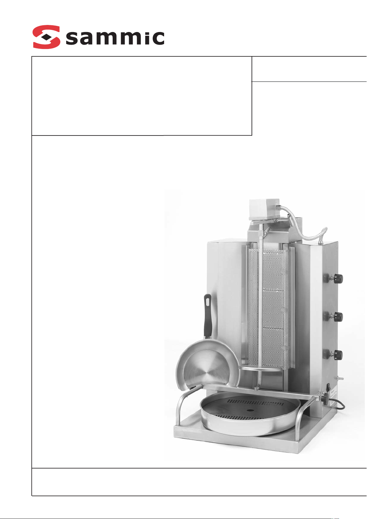
AG - 20/30/40
Asadores Gyros
Gas Gyros
Gas Gyros
Gyros à gaz
Ghiros a gas
Assadores Gyros
Page 2

INSTALACIÓN
Aviso
ESTE APARATO DEBE SER INSTALADO POR
TECNICO ESPECIALIZADO, DE ACUERDO
CON LAS LEYES Y LAS REGULACIONES QUE
ESTAN EN VIGOR EN EL PAIS DE DESTINO,
DONDE EL APARATO VA A SER UTILIZADO.
Normas de seguridad para la instalación
Para su instalación es necesario un con-
ducto de extraccion de productos de la
combustión.
Debe ser instalado y conectado de acuerdo
con las regulaciones que están en vigor.
Se debe dar suma importancia a los siste-
mas de la ventilación que usen.
La instalación, la conexión y la mantenimien-
to, se debe realizar solamente por técnicos
especializados, teniendo en cuenta las pre-
sentes instrucciones, así como las órdenes
correspondientes que se relacionan con el
lugar donde va a ser instalado el aparato.
Este aparato se prohibe instalarse y utili-
zarse en sotanos.
Se prohibe estrictamente la instalación, el
uso y el mantenimiento de este aparato por
los niños. Alejen a los niños y curriosos
mientras que el aparato está en funciona-
miento.
El aparato debe ser instalado en una super-
ficie horizontal que resista a una exposi-
ción permanente de temperatura mínima
de 90° C. Se prohiben todas las superficies
inflamables.
Para una ventilación adecuada debe existir
un hueco de al menos 0.20m alrededor del
aparato.
No cuelguen nada por encima del aparato a
una distancia inferior de 1.5 metros, por-
que la temperatura por encima del conduc-
to de escape (2), Figura A, es muy alta.
La altura entre la superficie en la que va a ins-
talarse el aparato, debe tener al menos una
altura desde el suelo entre 0.70m y 0.90m.
Conexión
La conexión del aparato se hace de tres
maneras, dependiendo del tipo de gas que
se va a utilizar.
El punto de conexión (4), Figura B, del apa-
rato y el conducto de gas, está situada en
la parte trasera del aparato.
Uso del aparato con Butano y Propano
Butano: Usar un regulador aprobado de
baja presión 28mbar.
Propano: Usar un regulador aprobado de
baja presión 37mbar.
En este caso puede usar la tobera de cone-
xión (1), Figura B, que acompaña al apara-
to, para que la conecten con un tubo flexi-
ble. Atornillen la tobera en la parte trasera
del aparato, en el encaje (4), con un diáme-
tro de 16mm (3/8).
Este tubo debe estar aprobado para este
uso.
Tienen que controlar la fecha del reempla-
zamiento del tubo.
Tienen que instalarlo de tal modo, que sea
visible toda su longitud (desde el aparato
hasta la llave de suministro o hasta la
botella).
El control para ver si las conexiones son her-
méticas para evitar el escape de gas debe
hacerse con la ayuda de agua jabonada.
Es decir, abran la botella o la llave de sumi-
nistro para permitir la circulación del gas y
asegúrense si la conexión es correcta, con-
trolada por la falta de burbujas del aire,
con la cual han cubierto las conexiones.
PELIGRO: SE PROHIBE ESTRICTAMENTE EL
USO DE LLAMAS, PARA CONTROLAR SI LAS
CONEXIONES SON HERMETICAS.
Uso del aparato con Gas Natural
Esta conexión puede hacerse con la ayuda
de la tobera (2), Figura B, cuando vaya a
utilizar un tubo flexible siguiendo las ins-
trucciones del parrafo anterior para la
conexión y el control hermético.
Si quieren hacer una conexión fija y perma-
nente con un tubo fuerte atornillado, será
necesario usar la tobera (3),Figura B.
Esta es la conexión que se recomienda.
PELIGRO: SE PROHIBE ESTRICTAMENTE EL
USO DE LLAMAS PARA CONTROLAR SI LAS
CONEXIONES SON HERMÉTICAS.
Uso del aparato con Propano & Butano
50mbar
Butano: Usar un regulador aprobado de
baja presión 50mbar.
Propano: Usar un regulador aprobado de
baja presión 50mbar.
Esta conexión puede hacerse con la ayuda
de la tobera (1), Figura B, cuando vaya a
utilizar un tubo flexible siguiendo las ins-
trucciones del párrafo anterior 3.1 para la
conexión y el control hermético.
Si quieren hacer una conexión fija y perma-
nente con un tubo fuerte atornillado , será
necesario usar la tobera (3),Figura B.
Esta es la conexión que se recomienda
PELIGRO: SE PROHIBE ESTRICTAMENTE EL
USO DE LLAMAS PARA CONTROLAR SI LAS
CONEXIONES SON HERMÉTICAS.
FUERZA ELECTRICA: El aparato está conec-
tado en la red electrica, usando un enchu-
fe de seguridad, 230 V, 50 Hz, conectado a
tierra.
TERMINAL EQUIPOTENTIAL: Ese terminal en
la parte trasera del aparato, sirve solamen-
te para conectar dos o más aparatos entre
ellos.
2
ES
Page 3

3
ES
Adaptación para el cambio del Gas
En la entrega, todos los aparatos están
adaptados por la industria, para que se
usen con Propano 37mbar (G31) o Butano
28mbar (G30). Sin embargo es necesario
determinar, si el regulador de presión baja
que está usando, está aprobado para
Propano 37mbar o para Butano 28mbar
respectivamente.
En el caso que el aparato se utilice con Gas
Natural o con Propano y Butano de presión
50mbar, se deben hacer las siguientes
regulaciones después de su conexión sola-
mente por técnico especializado como se
explica en los parrafos 4.1, 4.2 y 4.3:
- cambio de los pulverizadores ( beck).
- regulación de la entrada del aire en el
quemador.
- regulación de la llave de suministro de
cada quemador en la posición 'mini-
mum' (llama pequeña).
Cambio de los pulverizadores (beck)
El siguiente procedimiento se hace
teniendo cerrado el suministro de gas y
con el aparato desconectado del enchufe
eléctrico.
Para cambiar los pulverizadores (beck)
deben retirar la parte trasera de la máqui-
na. Después deben cambiar los pulveriza-
dores teniendo el aparato abierto por la
parte trasera o para una mayor comodidad
tienen que retirar toda la base de los que-
madores (2), Figura C. Para hacer ésto
deben destornillar los cuatro (1), Figura C,
los cuales sujetanla base en su lugar.
Retirar la base tirando hacia usted.
En la parte de atrás de cada una de las vál-
vulas termomagnéticas (1), Figura D, se
encuentran los pulverizadores (2). Con la
ayuda de una llave número 7, o con un
destornillador especial número 7, destor-
nillen los pulverizadores y reemplacenlos
por los pulverizadores que van a encontrar
dentro del embalaje del aparato bien con la
indicación 'Gas Natural' o bien con la indi-
cación 'I3 B/P : 50mbar', dependiendo del
gas que van a utilizar.
Regulación de la entrada del aire en el
quemador
El siguiente procedimiento se hace tenien-
do cerrado el suministro del gas y el apa-
rato desconectado del enchufe eléctrico.
Ahora se debe regular la entrada del aire en
el quemador por el aro (3), Figura D, que se
encuentra situado en el quemador y se
sostiene con el tornillo (4). Aflojen el torni-
llo (4) un poco , coloquen el aro en tal posi-
ción que tenga la distancia sea d= 10 mm,
para ´'Gas Natural' y d= 25 mm para el 'I3
B/P:50mbar'. Después aprieten de nuevo el
tornillo (4), de tal manera que el aro (3)
esté apropiadamente asegurado en el que-
mador.
Vuelvan a poner los quemadores en su
posición, colocándolos con cuidado
correctamente y atornillen los tornillos que
habían quitado. Coloquen en su lugar las
placas de asar y el cajón del aparato.
Regulación de la llave de suministro de
cada quemador en la posición 'minimum'
(llama pequeña)
El procedimiento siguiente se hace una vez
completados todos los procedimientos que
se describen en los parrafos anteriores 4.1
y 4.2.
Deben regular todas las válvulas termo-
magnéticas del aparato.
Después de haberse llevado a cabo la ins-
talación y la conexión del aparato según las
instrucciones anteriores, enciendan el que-
mador según las instrucciones del parrafo
B.2 Combustión.
Giren los botones de las válvulas termo-
magnéticas (1), Figura E, en la posición
'minimum' (llama pequeña), y saquénlas
tirando hacia fuera.
El tornillo de regulación se encuentra en el
agujero (2), Figura E, exactamente encima de
cada válvula termomagnética. Con la ayuda de
un destornillador especial muy fino, de anchu-
ra 2mm, regulen la intensidad de la llama que
deseen en cada quemador,empezando por el
quemador más bajo y avanzando hacia arriba.
No se olviden mantener las válvulas termo-
magnéticas en la posición 'minimum' (llama
pequeña).
Girando el destornillador hacia la izquie-
dra, la llama aumenta, mientras que hacia
la derecha disminuye, como se ve en la
Figura E. El aparato está bien regulado
cuando tiene una llama azul estable en el
quemador.
Se consigue una regulación correcta cuan-
do todos los quemadores han obtenido una
intensidad uniforme, la cual se ve por la
uniformidad de su color.
Es mucho más fácil hacer esta adaptación
con las luces un poco débiles.
Coloquen de nuevo en su lugar los botónes
de manipulación (1) de las válvulas termo-
magnéticas y apaguen el aparato girándo-
los en la posición (apagado).
USO
Normas de seguridad de uso
ESTE APARATO ESTÁ DESTINADO SOLAMEN-
TE PARA USO PROFESIONAL Y DEBE UTILI-
ZARSE POR PERSONAL ESPECIALIZADO.
Se prohibe estrictamente la instalación, el
uso y el mantenimiento del aparato por los
niños. Alejen a los niños y curiosos mien-
tras el aparato está en funcionamiento.
Se prohibe estrictamente el uso del apara-
to para cualquier otra razón, excepto para
asar la carne.
Page 4

Limpien frecuentemente las partes del apa-
rato donde se acumula la grasa para que se
evite su combustión a causa de recalenta-
miento.
Se prohibe estrictamente la colocación de
cualquier tipo de utensilios encima del
aparato (ollas, sartenes, bandejas, instru-
mentos, etc).
Se prohibe estrictamente echar liquidos en
el aparato ( aceite, agua, salsas etc).
Combustión
Una vez que el aparato está conectado de
acuerdo con las instrucciones anterior-
mente mencionadas, abran la válvula de
gas del aparato.
Cada uno de los quemadores infrarrojos
(10), Figura A, tiene su propio botón de
manipulación de la válvula termomagnética
(13), con el cual regula su intesidad.
El aparato se entrega con los botones de
las válvulas termomagnéticas cerradas, o
sea en la posición (apagado).
Cuando deseen encender el aparato, con una
mano gire hacia el lado izquierdo el botón de
la válvula termomagnética más baja (13),
sujetándolo a la vez en la posición (chispa).
Con la otra mano encienda el quemador
utilizando un encendedor. El quemador
infrarrojo más bajo se ha encendido.
Continue teniendo apretado el botón de la
válvula termomagnética (13) aproximada-
mente 15" segundos. En el caso de que el
quemador no se encienda, repita el proce-
dimiento anterior.
Ahora puede encender el segundo, el tercer
quemador infrarrojo... etc, avanzando para
mayor facilidad y para que eviten el uso del
encendedor, del quemador más bajo hacia
arriba.
Cada quemador debe encenderse de la
misma manera que el quemador más bajo,
lo que significa que debe mantener el
botón de la válvula termomagnética apre-
tado durante unos 15" segundos.
Regulen a su preferencia la intensidad de
cada quemador, girando lentamente los
botones de manipulación (4), hacia la posi-
ción 'minimum' (llama pequeña).
La temperatura alta o baja de los quema-
dores se consigue girando los botones de
manipulación (4) hacia la izquiedra o hacia
la derecha.
Para poner el motor en función, presionen el
interuptor (14), Figura A, en la posición ( I ).
Para colocar el asador en su lugar, primero
ponga su parte superior en la extención
debajo del motor, y después la parte infe-
rior en el centro de la base del asador (7).
Después asegure el asador en su parte de
arriba, con su 'chincheta asador' especial
de seguridad, lo cual acompaña al aparato.
La parte de arriba del asador se puede
mover destornillandola parte superior de la
abrazadera del asador (8), Figura A y la
parte de abajo, los dos asadores (8), que
están situadas en la parte izquiedra y dere-
cha de la base del asador.
NOTA 1: Este aparato tiene una grande
ventaja. Incluso en caso de corte de
corriente eléctrica o averia del motor pue-
den ustedes continuar el asado manual-
mente, quitando simplemente la 'chincheta
asador', que conecta el asador con el
motor.
NOTA 2: El borde metálico que acompaña
al aparato, se coloca para facilitar la prepa-
ración de la carne.
Apagado
Para que apaguen el aparato, tienen que
girar todos los botones de las válvulas ter-
momagnéticas (13), en la posición (apaga-
do), para que se apaguen los quemadores
infrarrojos.
Después, presione el interruptor del motor
(14), en la posición (O).
El aparato está apagado.
Ventilación
Durante el asado sale humo ya que se
quema la grasa que tiene la carne. Por esta
razón debe ventilarse bien el lugar donde
se utilice el aparato, bien con la ayuda de
un mecanismo específico de ventilación
(extractor de olores) o bien abriendo algu-
na ventana.
Siempre deben tener cuidado de no cubrir
el conducto de escape (2), Figura A.
MANTENIMIENTO
Limpieza y Mantenimiento
CUIDADO: ESTA ESTRICTAMENTE PROHIBI-
DO LIMPIAR EL APARATO CON CHORROS
DE AGUA.
LA LIMPIEZA REGULAR AYUDA AL CORREC-
TO Y BUEN FUNCIONAMIENTO DEL APARA-
TO.
LIMPIEN FRECUENTEMENTE LAS PARTES DEL
APARATO DONDE LA GRASA SE ACUMULA, PARA
QUE SE EVITE EL PELIGRO DE COMBUSTIÓN
A CAUSA DE RECALENTAMIENTO.
Durante la limpieza tanto el aparato como el
conducto de gas deben estar cerrados y el
cable desconectado del enchufe eléctrico.
Pueden quitar facilmente el asador y el
recolector de la grasa para que los limpien.
Pueden lavarlos con productos de limpieza
comercial , y frotar con cepillo de alambre
o con otro medio.
Enjuaguen siempre bien con abundante
agua y séquenlos bien antes de volver a
usarlos.
También limpien todas las partes de las
superficies exteriores del aparato, donde
se haya acumulado grasa.
Coloquen de nuevo de manera correcta
todos los accesorios, que se habian quita-
do para limpiarse.
4
ES
Page 5

El aparato ya está listo para usarse de
nuevo.
LISTA DE PIEZAS DE RECAMBIO & POSIBLES AVERIAS
1. Válvula de gas termomagnética: Se debe
reemplazar cuando se observe mal fun-
cionamiento en la rotación del eje (está
"muy ajustado" o se ha torcido).
También en caso de que se observe
escape de gas cerca del eje o del cuerpo
de la válvula.
ENGRASADO: Cada válvula de gas termo-
magnética se debe revisar una vez al año
para ser engrasada en su parte interna.
2. Termopar: Se debe reemplazar cuando
se obseve que el quemador no perma-
nece encendido tras el proceso de
encendido, a pesar de que el extremo
del termopar se encuentre dentro de la
llama.
2. Unidad Magnética: Se encuentra dentro
de la válvula de gas termomagnética. Se
debe reemplazar cuando se observe que
el quemador no permanece encendido
tras el proceso de encendido pero sola-
mente en el caso de que se esté seguro
de que el termopar funciona con norma-
lidad y esté bien atornillado.
4. Rejilla Frontal: Se debe reemplazar
cuando se haya agujereado de modo que
interrumpa el asado de la carne.
5. Motor: Se debe reemplazar cuando se
observe mal funcionamiento durante la
rotación o cuando no gire en absoluto,
tras asegurarse previamente de que el
resto del circuito eléctrico funciona
correctamente.
6. Interruptor del motor: Se debe reempla-
zar cuando se observe mal funciona-
miento del interruptor al pretarlo cuan-
do desee que el motor comience a rotar
o cuando el motor no gire en absoluto,
tras asegurarse previamente de que el
motor y el resto del circuito eléctrico
funcionan correctamente.
7. Cables del circuito eléctrico: Los cables
del circuito eléctrico que unen el motor
con el interruptor y que pasan por enci-
ma de puntos calientes del aparato, se
deben reemplazar cada año. El resto de
cables deben ser comprobados de forma
regular para asegurarse de que se
encuentran en buen estado.
8. Cable de Suministro: Si el cable de sumi-
nistro esta averiado, tiene que ser reem-
plazado por el fabricante, por su servicio
autorizado o por semejante personal
calificada, con el objetivo de evitar cual-
quier peligro.
ATENCIÓN: Las operaciones referidas en
todos los casos anteriores se deben llevar a
cabo solamente por técnicos especialistas.
OTRAS OBSERVACIONES IMPORTANTES
-
Este aparato no está destinado para ser
usado por personas (incluido niños) cuyas
capacidades físicas, sensoriales o mentales
estén reducidas, o carezcan de experiencia
o conocimiento, salvo si han tenido super-
visión o instrucciones relativas al uso del
aparato por una persona responsable de su
seguridad.
5
ES
Page 6

INSTALLATION
Warning
THIS APPLIANCE MUST BE INSTALLED BY A
SPECIALIST TECHNICIAN ACCORDING TO
THE LAWS AND REGULATIONS IN FORCE IN
THE COUNTRY OF DESTINATION, IN WHICH
THE APPLIANCE WILL BE USED.
Safety Rules for Installation
This appliance cannot be connected to a duct
for removing the products of combustion.
It must be installed and connected accor-
ding to the regulations in force.
Particular care must be taken with the ven-
tilation systems you use.
The installation, connection and mainte-
nance must be undertaken only by a spe-
cialist technician, taking into account all
the present instructions, as well as all the
remaining provisions concerning the site of
installation:
- An adequate flow of air in and out of the
area is needed.
- A site of at least 64m³ is required.
- A window, opening to at least 0.40m² is
required.
Installation and use of this appliance in
basement areas is prohibited.
The installation, use and maintenance of
this appliance by children is strictly prohi-
bited. Keep children and curious onlookers
away when the appliance is in operation.
The appliance must be installed on a hori-
zontal surface, with a constant heat resis-
tance of at least 90° C. All flammable sur-
faces are prohibited.
A space of 0.20m must be left around the
appliance for ventilation.
Do not hang anything over the appliance at
a distance of less than 1.5 metres, because
the temperature above the exhaust duct (2)
Figure A, is very high.
The height of the surface on which the
appliance is to be sited must be between
0.70m and 0.90m from the floor.
Connection
The appliance may be connected in three ways,
depending on the type of gas to be used.
The connection port (4) Figure B, between
the appliance and the gas supply is situa-
ted at the back side of the appliance.
Use of the Appliance with Butane and
Propane
Butane: Use an approved low pressure
regulator 28 - 30mbar.
Propane: Use an approved low pressure
regulator 37mbar.
In this case, you may use the connection
nozzle (1), Figure B, which accompanies the
appliance, to connect it with a flexible pipe.
Screw the nozzle on the backside of the
appliance, on the gas connection port (4),
with a diameter of 16 mm (3/8).
This pipe must be recognized for this use.
You must check the date of replacement of
the pipe.
You must install it in such a way that it is
visible along its whole length (from the
appliance to the supply tap or to the bottle).
The connections must be checked for leaks
in order to avoid gas escaping, with the
help of soapy water.
To do so: open the bottle or the supply-
tap, to allow the gas to circulate, and ensu-
re that the connection is correct by chec-
king for air bubbles in the soapy water
spread over the connections.
DANGER: THE USE OF A FLAME TO CHECK
FOR LEAKS AT CONNECTION POINTS IS
STRICTLY FORBIDDEN.
Use of the Appliance with Natural Gas
Connection may be made with the help of
the nozzle (2), Figure B, when a flexible
pipe is to be used, following the instruc-
tions on the previous paragraph with
regard to connection instructions and
checking for leaks.
If you wish to make a permanent, fixed
connection with a metallic pipe screwed
into position, it will be necessary to use the
nozzle (3), Figure B.
This is the recommended type of connec-
tion.
DANGER: THE USE OF A FLAME TO CHECK
FOR LEAKS AT CONNECTION POINTS IS
STRICTLY FORBIDDEN
Use of the Appliance with Propane &
Butane 50 mbar
Butane: Use an approved low pressure
regulator 50 mbar
Propane: Use an approved low pressure
regulator 50 mbar
Connection may be made with the help of
the nozzle (1), Figure B, when a flexible pipe
is to be used, following the instructions on
paragraph 3.1 with regard to connection
instructions and checking for leaks.
If you wish to make a permanent, fixed
connection with a metallic pipe screwed
into position, it will be necessary to use the
nozzle (3), Figure B.
This is the recommended type of connec-
tion.
DANGER: THE USE OF A FLAME TO CHECK
FOR LEAKS AT CONNECTION POINTS IS
STRICTLY FORBIDDEN
ELECTRIC POWER: The appliance is connec-
ted to the mains using a security socket,
230 V, 50 Hz, earthed.
6
EN
Page 7

EQUIPOTENTIAL TERMINAL: This terminal at
the back of the appliance, is only for connec-
ting two or more appliances together.
Adaptation for Gas Change
All appliances, on delivery, are factory adjus-
ted for use with Propane 37 mbar (G31) or
Butane 28- 30mbar (G30). However, it is
necessary to determine whether the low
pressure regulator you are using is approved
for 37 mbar Propane or 28- 30mbar for
Butane, respectively. In case the appliance is
to be used with natural gas, or with Propane
and Butane at a pressure of 50 mbar, the
following adjustments must be made after
installation only by a specialist technician, as
explained on paragraphs 4.1, 4.2 and 4.3:
- change of injectors.
- adjustment of the flow of air into the
burner.
- adjustment of the thermomagnetic gas
valve of each burner to the position
'minimum' (small flame).
Change of Injectors
The following procedure is followed having
the gas supply closed and the appliance
disconnected from the mains.
To change the injectors, you must first remove
the back of the appliance. The injectors may
then be changed, with the appliance open, or
for greater convenience, the whole base of the
burners (2) Figure C, may be removed.
To remove them, first unscrew the four
screws (1), Figure C, that hold it in position.
Remove the base by pulling it towards you.
On the back of each thermomagnetic gas
valve (1), Figure D, are the injectors (2).
With a number 7 spanner, or a special
screwdriver number 7, unscrew the injec-
tors and replace them with the injectors
you will find in the appliance packaging,
either those marked 'Natural Gas' or those
marked 'I3 B/P: 50 mbar', depending on the
gas you are using.
Adjustment of the Flow of Air into the
Burner
The following procedure is followed,
having the gas supply closed and the
appliance disconnected from the mains.
The flow of air into the burner must be
adjusted using the ring (3), Figure D, sited on
the burner and supported with a screw (4).
Loosen the screw (4), place the ring in a
position such that the distance d= 10mm
for Natural Gas and d= 25mm for the
'I3 B/P: 50 mbar'.
Tighten the screw (4) again so that the ring
(3) is properly secured on the burner.
Put the base of the burners back in position,
taking care to position them correctly and
replace the screws that have been removed.
Replace the back of the appliance.
Adjustment of the Thermomagnetic Gas
Valve of each Burner to the 'minimum'
position (small flame)
The following procedure is followed after
the procedures referred to on paragraphs
4.1 and 4.2 are completed.
All thermomagnetic gas valves of the
appliance must be adjusted.
After the appliance has been installed and
connected according to the above instruc-
tions, light the lower burner according to
the instructions on paragraph B.2 Ignition.
Turn the thermomagnetic valve knobs (1),
Figure E, to the 'minimum' position (small
flame) and then pull them out.
The adjustment screw is sited in the hole (2),
right above the thermomagnetic gas valve.
Using a very small screwdriver, 2 mm wide,
adjust the intensity of each burner, starting
from the lower radiant burner and moving
upwards.
Do not forget to keep all the gas valves at
the 'minimum' (small flame) position.
Turning the screwdriver to the left, the
flame gets larger, and to the right, the
flame gets smaller, as shown in Figure E.
The correct adjustment of the intensity
level is at exactly the point where the bur-
ner flame stops flickering.
A correct adjustment has been achieved
when all the radiant burners are at a uni-
form intensity level, which can be seen by
the uniformity of colour of them.
It is easier to make these adjustments with
the lights slightly dimmed.
Replace the valve knobs (1) and then turn
the appliance off, by turning the knobs
back to the position (off).
USE
Safety Rules for Use
THIS APPLIANCE IS DESTINED FOR PROFES-
SIONAL USE ONLY AND MUST BE USED BY
SKILLED PERSONNEL
Installation, use and maintenance of this
appliance by children is strictly prohibited.
Keep children and curious onlookers away
when the appliance is in operation.
Use of the appliance for any purpose other
than roasting meat is prohibited.
Placing utensils (e.g. pans, frying pans,
trays, tools etc) on the appliance is strictly
forbidden.
Clean the parts of the appliance where fat
may accumulate frequently, in order to
avoid its combustion due to overheating.
Pouring liquids (e.g. fat, water, sauces etc)
on the appliance is strictly forbidden.
Ignition
Having connected the appliance according
to the above directions, open the gas
supply to the appliance.
7
EN
Page 8

Each of the radiant burners (10) Figure A ,
has its own thermomagnetic valve knob
(13), which adjusts its intensity.
The appliance is delivered with the thermo-
magnetic valve knobs of the radiant bur-
ners closed, that is to the (off) position.
When you wish to start the appliance, with
one hand press down and turn the lower
thermomagnetic valve knob (13), to the
left, to the position (spark).
With the other hand approach a lit conven-
tional lighter in front of the lower radiant
burner.
The lower radiant burner is ignited.
Continue holding the thermomagnetic
valve knob (13) pressed down for about 15"
seconds.
In case the radiant burner fails to light,
repeat the above procedure.
You can now ignite the second, third... etc
radiant burners by moving, for greater
facility and to avoid using a lighter, from
the lower radiant burner, upwards.
Each radiant burner must be ignited in the
same way, as the lower radiant burner,
which means that you must keep the res-
pective thermomagnetic valve knob pres-
sed down for about 15" seconds.
Adjust the level of each radiant burner to
your preference, slowly turning the valve
knobs (13) towards the 'minimum' position
with the symbol (small flame).
The high or low temperature of the radiant
burners is achieved by turning the thermo-
magnetic valve knobs either to the left or to
the right.
To put the motor into operation, press the
motor switch (14) Figure A, to the (I) posi-
tion.
To place the spit in position, first put its
top side on the extension under the motor
and then its bottom side on the spit holder
(7) that is situated in its center.
Then, secure the spit on its top side with
the special safety "spit pin" that accompa-
nies the appliance.
The top side of the spit can be moved by
unscrewing the upper spit clamp (8), Figure
A, and the bottom, by unscrewing the two
bottom clamps (8), situated to the left and
right side of the spit holder (7).
NOTE 1: This appliance has a great advan-
tage. Even in case of power failure or
damage to the motor, you may continue to
roast the meat manually, by simply remo-
ving the safety "spit pin" that joins the spit
to the motor.
NOTE 2: The sharp metal component
accompanying the appliance is placed on
top of the spit, when preparing the meat,
so that it may be easily pierced. Keep it in
a safe place, away from children.
Turning Off
To turn the appliance off, first turn all the
thermomagnetic valve knobs (13) to the
position (off), so that the radiant burners
go out, too.
In order to stop the motor rotating, press
the motor switch (14) to the (O) position.
The appliance is then turned off.
Ventilation
During roasting, smoke is given off as the
fats of meat burn.
Therefore, the site where the appliance is
used must be sufficiently ventilated by ope-
ning a window or with the help of a special
ventilation mechanism (extractor fan).
Care must be taken never to cover the
exhaust duct (2) figure A.
MAINTENANCE
Cleaning & Maintenance
ATTENTION: IT IS STRICTLY FORBIDDEN TO
CLEAN THE APPLIANCE WITH WATER JETS.
REGULAR CLEANING HELPS TO THE PROPER
AND BETTER OPERATION OF THE APPLIANCE.
CLEAN THE PARTS OF THE APPLIANCE
WHERE FAT MAY ACCUMULATE, FRE-
QUENTLY, IN ORDER TO AVOID FAT COM-
BUSTION, DUE TO OVERHEATING.
During cleaning, the appliance as well as
the gas supply, should always be turned off
and disconnected from the mains.
You can easily remove the spit and the fat-
collector disk for cleaning.
You can wash them with brand- name clea-
ning materials and go over them with a
wire brush or similar means.
Also clean the outer surfaces of the
appliance where fat has accumulated.
Always rinse well, with water and dry befo-
re use.
Replace correctly all the above accessories
that were removed for cleaning.
The appliance is ready to be used again.
LIST OF SPARE PARTS
1. Thermomagnetic gas valve: It has to be
changed when you notice a malfunction
on the rotation of the axe (stiff, bent,
ect.) or when you notice leak of gas near
the axe, or the body of the valve.
GREASING: The thermomagnetic gas valve
must be checked for inside greasing, once
per year.
2. Thermocouple: It has to be changed
when you notice that it is not possible
for the burner to stay lit after you light it
up, although the nose of the thermo-
couple is inside the flame.
3. Magnet Unit: It is placed inside the ther-
momagnetic gas valve. It has to be
changed when you notice that it is not
possible for the burner to stay lit after
you light it up, but only if you are sure
8
EN
Page 9

that the thermocouple is working pro-
perly and is well screwed.
4. Face grid: It has to be changed when
there are holes or it is deformed or bro-
ken, so interrupt the cooking process.
5. Motor: It has to be changed when you
notice a malfunction on the rotation or
there is no rotation at all, although the
rest of the electric circuit is correct.
6. Motor switch: It has to be changed when
you notice a malfunction when you press
it, or when the motor does not tern at
all, although the rest of the electric cir-
cuit is correct.
7. Electric circuit cables: The cable of the
electric circuit that connects the motor
with the motor switch and pass over hot
arias of the appliance, must be changed
every year. The rest of the cables must
be checked often for their proper condi-
tion.
8. Supply Cable: If the supply cable is
damaged, it should be substituted by
the manufacturer, by its authorized ser-
vice or by similar qualified personal with
the objective to avoid a danger.
Attention: Only specialized technicians
should make the above cases.
OTHER IMPORTANT COMMENTS
- This machine is not designed to be used
by individuals (including children) with
reduced physical, sensorial or mental
facilities, or who lack the relevant expe-
rience or knowledge, unless they are
supervised by or have received instruc-
tion on how to use the apparatus from a
person responsible for their safety.
9
EN
Page 10

INSTALLIERUNG
Hinweis
DIESES GERÄT MUSS VON EINEM FACH-
MANN INSTALLIERT WERDEN UNTER EIN-
HALTUNG DER GÜLTIGEN GESETZE UND
REGELUNGEN DES BESTIMMUNGSLANDES,
IN WELCHEM DAS GERÄT VERWENDET WER-
DEN SOLL.
Sicherheitsvorschriften für die
Installierung
Dieses Gerät wird an keine Leitung zur Abfuhr
von Verbrennungsprodukten angeschlossen.
Es muss in Übereinstimmung mit den
jeweils gültigen Vorschriften installiert und
angeschlossen werden.
Den verwendeten Belüftungssystemen ist
eine besondere Bedeutung beizumessen.
Die Installierung, der Anschluss und die
Wartungsmassnahmen dürfen nur von
Fachkräften unter Beachtung dieser
Betriebsanleitung sowie der für den
Aufstellungsort bestehenden Vorschriften
durchgeführt werden:
Dieses Gerät darf nicht in Kellerräumen
aufgestellt und benutzt werden.
Das Gerät darf niemals von Kindern aufges-
tellt, benutzt und gewartet werden. Kinder
und Neugierige müssen während des
Betriebs vom Gerät ferngehalten werden.
Die Standfläche muss waagerecht und der
ständigen Aussetzung einer Temperatur
von mindestens 90º C gewachsen sein.
Brennbare Stellflächen sind unzulässig.
Durch Einhaltung eines Freiraumes von
mindestens 0,20 m um das Gerät herum
muss für eine geeignete Belüftung gesorgt
werden.
Es darf nichts in einem Abstand von weni-
ger als 1,5 m über dem Gerät aufgehängt
werden, weil in der Abluftleitung (2),
Abbildung A, sehr hohe Temperaturen
herrschen.
Die Standfläche, auf der das Gerät aufges-
tellt werden soll, muss einen Abstand von
mindestens 0,70 m bis 0,90 m zum
Fussboden bewahren.
Anschluss
Der Anschluss des Gerätes erfolgt auf drei
Arten, je nachdem welches Gas verwendet
wird.
Die Anschlussstelle (4), Abbildung B, des
Gerätes und die Gasleitung liegen auf der
Rückseite des Gerätes.
Verwendung des Gerätes mit Butan- und
Propangas
Butangas: Verwenden Sie einen geprüften
28mbar Niederdruckregler.
Propangas: Verwenden Sie einen geprüften
37mbar Niederdruckregler.
Für diesen Fall wird mit dem Gerät eine
Anschlussdüse (1), Abbildung B, mitgelie-
fert, an die Sie einen Schlauch anschliessen
können. Schrauben Sie die Düse auf der
Rückseite des Gerätes in der Aussparung
(4) mit einem Durchmesser von 16 mm
(3/8) fest.
Der Schlauch muss für diesen
Verwendungszweck zugelassen sein.
Überwachen Sie das Datum, an dem der
Schlauch ausgetauscht werden muss.
Der Schlauch muss so angebracht werden,
dass er in seiner ganzen Länge sichtbar ist
(vom Gerät bis zum Gashahn oder bis zur
Gasflasche).
Um nachzuprüfen, ob die Anschlüsse gas-
dicht sind und um ein Entweichen von Gas
verhindern zu können, verwenden Sie am
besten Seifenwasser.
Öffnen Sie die Flasche oder den Gashahn,
damit das Gas durch die Leitung strömen
kann. Der Anschluss ist perfekt, wenn sich
an den zuvor mit Seifenwasser befeuchte-
ten Anschlüssen keine Luftblasen bilden.
VORSICHT: ES IST STRENGSTENS VERBOTEN,
ZUM PRÜFEN DER GASDICHTIGKEIT DER
ANSCHLÜSSE EINE FLAMME ZU BENUTZEN.
Verwendung des Gerätes mit Erdgas
Wenn ein Schlauch verwendet werden soll,
können Sie diesen Anschluss mit der Düse
(2), Abbildung B, herstellen. Anschluss und
Prüfung der Gasdichtigkeit wie im vorheri-
gen Abschnitt beschrieben.
Für einen festen und dauerhaften
Anschluss mit einem widerstandsfähigen
angeschraubten Rohr verwenden Sie bitte
die Düse (3), Abbildung B.
Empfohlen wird diese letzte
Anschlussmöglichkeit.
VORSICHT: ES IST STRENGSTENS VERBO-
TEN, ZUM PRÜFEN DER GASDICHTIGKEIT
DER ANSCHLÜSSE EINE FLAMME ZU BENUT-
ZEN.
Verwendung des Gerätes mit Propanund Butangas bei 50mbar
Butangas: Verwenden Sie einen geprüften
50mbar Niederdruckregler.
Propan: Verwenden Sie einen geprüften
50mbar Niederdruckregler.
Wenn ein Schlauch verwendet werden soll,
können Sie den Anschluss mit der Düse (1)
Abbildung B, herstellen. Anschluss und
Prüfung der Gasdichtigkeit wie im vorheri-
gen Abschnitt 3.1 beschrieben.
Für einen festen und dauerhaften
Anschluss mit einem widerstandsfähigen
angeschraubten Rohr verwenden Sie bitte
die Düse (3), Abbildung B.
Empfohlen wird diese letzte
Anschlussmöglichkeit.
10
DE
Page 11

11
DE
VORSICHT: ES IST STRENGSTENS VERBOTEN,
ZUM PRÜFEN DER GASDICHTIGKEIT DER
ANSCHLÜSSE EINE FLAMME ZU BENUTZEN.
ELEKTRISCHER STROM: Das Gerät ist über
einen geerdeten Sicherheitsstecker für
230V, 50 Hz, an das Stromversorgungsnetz
angeschlossen.
ISOELEKTRISCHE ANSCHLUSSKLEMME.
Dieser Anschluss auf der Geräterückseite
hat den einzigen Zweck, zwei oder mehr
Geräte untereinander zu verbinden.
Anpassung für Gaswechsel
Die Geräte sind bei ihrer Auslieferung alle für
die Verwendung von Propangas 37mbar
(G31) oder Butangas 28mbar (G30) ange-
passt. Es muss jedoch noch festgestellt wer-
den, ob der verwendete Niederdruckregler
für Propan 37mbar oder für Butan 28mbar
zugelassen ist.
Sollte das Gerät mit Erdgas oder mit
Propangas und Butangas bei 50mbar Druck
verwendet werden, so sind folgende
Eingriffe vorzunehmen, nachdem das Gerät
von einem Fachmann gemäss den
Erklärungen unter Punkt 4.1, 4.2 und 4.3
angeschlossen worden ist:
- Austauschen der Injektoren ( beck).
- Einstellen des Lufteintritts in den Brenner.
- Einstellen des Gaseinlassreglers jeden ein-
zelnen Brenners auf die Minimalposition
(kleine Flamme).
Austauschen der Injektoren (beck)
Bei diesem Vorgang muss der Gashahn
zugedreht und das Gerät von der
Stromleitung abgetrennt sein.
Zum Austauschen der Injektoren (beck)
muss die Rückseite des Gerätes entfernt
werden. Das Austauschen der Injektoren
findet bei offener Rückseite statt.
Bequemer ist es, wenn man die gesamte
Grundplatte der Brenner entfernt (2),
Abbildung C. Lösen Sie hierzu die vier
Schrauben (1), Abbildung C, die die
Grundplatte an ihrem Platz festhalten.
Entfernen Sie die Platte, indem Sie sie zu
sich herausziehen.
Am hinteren Teil der einzelnen
Thermomagnetventile (1), Abbildung D,
befinden sich die Injektoren (2). Schrauben
Sie mit Hilfe eines Schraubenschlüssels Nr. 7
oder mit einem Spezialschraubenzieher 7 die
Injektoren heraus und ersetzen Sie sie durch
die Injektoren, die Sie in der Verpackung des
Gerätes mit der Angabe 'Naturgas' oder 'I3
B/P : 50mbar' finden, je nachdem, welches
Gas verwendet werden soll.
Regeln des Lufteintritts in den Brenner
Bei diesem Vorgang muss der Gashahn
zugedreht und das Gerät von der
Stromleitung getrennt sein.
Die Luftzufuhr wird über den Ring (3),
Abbildung D, eingestellt, der sich am
Brenner befindet und von der Schraube (4)
gehalten wird. Lockern Sie die Schraube (4)
ein wenig und stellen Sie den Ring so ein,
dass der Abstand d = 10 mm für "Erdgas"
und d= 25 mm für 'I3 B/P:50mbar' ist.
Ziehen Sie nun die Schraube (4) wieder fest,
so dass der Ring (3) genügend fest am
Brenner sitzt.
Bringen Sie die Brenner wieder in ihre urs-
prüngliche Lage und schrauben Sie die
abgenommenen Schrauben wieder ein.
Einstellen des Gaseinlassreglers jeden
einzelnen Brenners auf die
Minimalposition (kleine Flamme)
Der nachstehende Vorgang findet statt,
wenn alle in den Abschnitten 4.1 und 4.2
beschriebenen Massnahmen getroffen
worden sind.
Es müssen alle Thermomagnetventile des
Gerätes eingestellt werden.
Nachdem das Gerät gemäss der vorherigen
Anleitung installiert und angeschlossen
worden ist, zünden Sie den Brenner an und
beachten Sie dabei die Angaben im
Abschnitt B.2 Verbrennung.
Drehen Sie die Stellknöpfe der
Thermomagnetventile (2), Abbildung E, auf
die Position "Minimum" (kleine Flamme)
und ziehen Sie die Knöpfe heraus.
Die Verstellschraube befindet sich in der
Öffnung (2), Abbildung E, genau über
jedem Thermomagnetventil. Mit einem
sehr feinen Spezialschraubendreher, Breite
2mm, stellen Sie nun für jeden Brenner die
gewünschte Flammengrösse ein.
Angefangen wird beim untersten Brenner
und dann aufwärts.
Achten Sie darauf, dass die
Thermomagnetventile immer auf
"Minimum" (kleine Flamme) stehen.
Bei Linksdrehung des Schraubenziehers
vergrössert sich die Flamme, nach rechts
wird die Flamme kleiner, siehe hierzu
Abbildung E. Das Gerät ist richtig einges-
tellt, wenn der Brenner eine gleichmässige
blaue Flamme aufweist.
Die Einstellung ist korrekt, wenn alle
Brenner die gleiche Brennintensität erzielt
haben, was an der gleichmässigen Färbung
der Flammen zu erkennen ist.
Bei einer etwas schwachen Beleuchtung
lässt sich diese Einstellung leichter vorneh-
men.
Stecken Sie die Stellknöpfe (1) der
Thermomagnetventile wieder auf und
schalten Sie das Gerät aus, indem Sie die-
selben auf () stellen.
GEBRAUCH
Sicherheitshinweise für den Gebrauch
DIESES GERÄT IST NUR FÜR GEWERBLICHEN
GEBRAUCH VORGESEHEN UND MUSS VON
Page 12

FACHKUNDIGEM PERSONAL BEDIENT WER-
DEN.
Das Gerät darf niemals von Kindern auf-
gestellt, benutzt und gewartet werden.
Kinder und Neugierige müssen während
des Betriebs vom Gerät ferngehalten wer-
den.
Es ist strengstens untersagt, das Gerät für
einen anderen Zweck als zum Braten von
Fleisch verwendet werden.
Reinigen Sie regelmässig die Geräteteile, an
denen sich Fett ansammelt, damit dieses
aufgrund von Überhitzing nicht verbrennt.
Es dürfen auf keinen Fall irgendwelche
Utensilien auf dem Gerät abgestellt werden
(Töpfe, Pfannen, Bleche, Instrumente usw.).
Es dürfen auf keinen Fall Flüssigkeiten (Öl,
Wasser, Sossen usw.) auf das Gerät gegos-
sen werden.
Verbrennung
Nachdem das Gerät entsprechend den obi-
gen Hinweisen angeschlossen worden ist,
öffnen Sie bitte das Gasventil am Gerät.
Jeder der Infrarotbrenner (10), Abbildung
A, besitzt einen eigenen Stellknopf für das
Thermomagnetventil (13), mit dem die
Intensität reguliert wird.
Bei Auslieferung des Gerätes sind die
Stellknöpfe der Thermomagnetventile ges-
chlossen, d.h. in der Position (Funke).
Zum Anzünden des Gerätes drehen Sie
bitte mit einer Hand den Stellknopf des
untersten Thermomagnetventils (13) nach
links und halten Sie es in der Position ()
fest. Mit der anderen Hand zünden Sie nun
den Brenner mit Hilfe eines Anzünders an.
Der unterste Infrarotbrenner ist angezün-
det.
Halten Sie den Knopf des
Thermomagnetventils (13) noch etwa 15
Sekunden lang gedrückt. Falls der Brenner
nicht anzündet muss der obige Vorgang
wiederholt werden.
Nun können Sie den zweiten, dritten... usw.
Infrarotbrenner anzünden. Zünden Sie am
besten der Reihe nach von unten nach oben
die Brenner an, denn so benötigen Sie kei-
nen Anzünder mehr.
Jeder Brenner muss wie der unterste ange-
zündet werden, das heisst Sie müssen
jedesmal den Knopf des
Thermomagnetventils 15 Sekunden lang
eingedrückt halten.
Stellen Sie nach Wunsch die Intensität der
einzelnen Brenner ein, indem Sie die
Stellknöpfe (4) langsam in Richtung auf die
"Minimum" Position drehen (kleine
Flamme).
Durch Drehen der Stellknöpfe (4) nach links
oder rechts stellen Sie die Temperatur
höher oder niedriger.
Zum Ingangsetzen des Motors stellen Sie
bitte den Schalter (14), Abbildung A, auf ( I ).
Zum Anbringen des Grillspiesses stecken
Sie zuerst das obere Ende in die
Vorrichtung unterhalb des Motors und
dann das untere Ende in die Mitte der
Grundplatte des Gerätes (7).
Befestigen Sie dann den Spiess am oberen
Teil mit Hilfe der mitgelieferten
Spezialsicherung.
Das Teil oben am Grillspiess lässt sich
verschieben, wenn man die Schraube des
Befestigungshakens am Grillspiess (8),
Abbildung A, lockert. Ebenso lassen sich
die beiden Befestigungsschrauben links
und rechts unten am Grillspiess bewegen.
Hinweis 1: Dieses Gerät hat einen grossen
Vorteil. Bei Stromausfall oder
Motorschaden können Sie von Hand wei-
tergrillen, indem Sie lediglich den Stift ent-
fernen, der den Spiess mit dem Motor ver-
bindet.
Hinweis 2: Der mitgelieferte Metallrahmen
dient zum Herrichten des Fleisches.
Ausschalten
Zum Ausschalten des Gerätes drehen Sie
bitte alle Stellknöpfe der Thermomagnet-
ventile (13) auf die Position (), damit die
Infrarotbrenner erlöschen.
Schalten Sie anschliessend den
Motorschalter (14) auf die Position (O). Das
Gerät ist nun ausgeschaltet.
Lüftung
Beim Grillen entsteht Rauch, denn das Fett
im Fleisch verbrennt. Deshalb muss der Ort,
an dem das Gerät aufgestellt wird, gut belüf-
tet sein, entweder anhand einer besonderen
Belüftungsvorrichtung (Rauchabzug) oder
durch Öffnen eines Fensters.
Achten Sie darauf, dass die Abluftleitung
(2), Abbildung A, niemals zugedeckt wird.
WARTUNG
Reinigung und Wartung
VORSICHT: ES IST STRENGSTENS UNTER-
SAGT, DAS GERÄT MIT DEM WASSERSTRAHL
ZU REINIGEN.
EIN REGELMÄSSIGES REINIGEN SORGT FÜR
EINEN EINWANDFREIEN BETRIEB DES
GERÄTES.
REINIGEN SIE REGELMÄSSIG DIE
GERÄTETEILE, AN DENEN SICH FETT
ANSAMMELT, DAMIT DIESES AUFGRUND
VON ÜBERHITZUNG NICHT VERBRENNT.
Beim Reinigen muss sowohl das Gerät wie
auch die Abluftleitung geschlossen und das
Kabel aus der Steckdose gezogen sein.
Grillspiess und Fettwanne lassen sich zum
Reinigen leicht herausnehmen.
Zur Reinigung empfiehlt sich ein im Handel
erhältliches Produkt. Sie können auch eine
Stahlbürste o.ä. zu Hilfe nehmen.
12
DE
Page 13

Zum Abschluss immer mit reichlich Wasser
nachspülen und die Teile gründlich abtrock-
nen bevor sie wieder benutzt werden.
Reinigen Sie auch die äusseren Oberflächen
des Gerätes, an denen sich Fett abgesetzt hat.
Bringen Sie alle Teile, die Sie zum Reinigen
abgenommen haben, wieder an ihrer rich-
tigen Stelle an.
Nun ist das Gerät wieder gebrauchsbereit.
ERSATZTEILLISTE & MÖGLICHE STÖRUNGEN
1. Thermomagnetventil: Austauschen,
sobald sich die Achse nicht mehr ein-
wandfrei drehen lässt (sitzt sehr fest
oder hat sich verformt). Austauschen,
wenn dicht an der Achse oder am
Ventilkörper ein Entweichen von Gas
beobachtet wird.
SCHMIEREN: Jedes der thermomagnetis-
chen Gasventile muss einmal pro Jahr auf
seine Funktion überprüft und in seinem
Innenraum nachgeschmiert werden.
2. Thermopaar: Das Thermopaar muss
ausgetauscht werden, wenn der Brenner
nach dem Anzünden nicht anbleibt,
obwohl das Ende des Thermopaars in
der Flamme liegt.
3. Magneteinheit: Diese befindet sich im
thermomagnetischen Gasventil und
muss erneuert werden, wenn der
Brenner nach dem Anzünden nicht
anbleibt, aber nur wenn Sicherheit bes-
teht, dass das Thermopaar normal funk-
tioniert und gut festgeschraubt ist.
4. Brennergitter: Das Gitter muss erneuert
werden, sobald es Löcher bekommen
hat, die beim Grillen stören.
5. Motor: Der Motor muss erneuert werden,
sobald er schlecht dreht oder nicht mehr dreht
nachdem sichergestellt ist, dass der restliche
Stromkreis einwandfrei funktioniert.
6. Motorschalter: Der Schalter muss erneuert
werden, wenn er beim Einschalten des
Motors schlecht funktioniert oder wenn
der Motor sich überhaupt nicht dreht,
nachdem sichergestellt ist, dass der Motor
und der restliche Stromkreis einwandfrei
funktionieren.
7. Kabel des elektrischen Stromkreises:Die
Kabel des Stromkreises, die den Motor
mit dem Schalter verbinden und heisse
Stellen des Gerätes überqueren, müssen
einmal pro Jahr erneuert werden. Die
restlichen Kabel müssen regelmässig auf
ihren einwandfreien Zustand überprüft
werden.
8. Zuleitungskabel: Ein schadhaftes
Zuleitungskabel muss vom Hersteller,
von einer vom Hersteller zugelassenen
Kundendienststelle.
ACHTUNG: Alle in den obigen Fällen
erwähnten Vorgänge dürfen nur von fach-
kundigen Technikern ausgeführt werden.
ANDERE WICHTIGE HINWEISE
-
Dieses Gerät darf nicht von Personen
(einschl. Kindern) benutzt werden, die in
ihren körperlichen, sensorischen oder
geistigen Fähigkeiten behindert sind oder
nicht über die erforderliche Erfahrung und
Kenntnis verfügen, es sei denn sie sind von
einer für ihre Sicherheit verantwortliche
Person in den Gebrauch des Gerätes einge-
wiesen oder dabei überwacht worden.
13
DE
Page 14

INSTALLATION
Avertissement
CET APPAREIL DOIT ÊTRE INSTALLÉ PAR UN
TECHNICIEN QUALIFIÉ, CONFORMÉMENT
AUX LOIS ET RÈGLES EN VIGUEUR DANS LE
PAYS DE DESTINATION ET D'INSTALLATION.
Règles de Sécurité pour l'Installation
Cet appareil ne peut pas être raccordé à
une conduite d'évacuation des produits de
combustion.
Il faut qu'il soit installé et raccordé confor-
mément à la réglementation en vigueur.
Une attention particulière sera accordée
aux systèmes de ventilation utilisés.
L'installation, le raccordement et l'entretien
doivent être confiés à un technicien quali-
fié, qui prendra en compte les instructions
de cette notice, ainsi que toutes les provi-
sions respectives concernant la pièce ou
l'endroit où l'appareil sera installé:
- La pièce sera équipée d'une entrée et
d'une sortie d'air satisfaisantes.
- La pièce aura une superficie d'au moins
64m³.
- Une fenêtre à ouverture d'au moins
0.40m² est également indispensable.
Il est interdit d'installer et d'utiliser cet
appareil en sous- sol.
L'installation, usage ou entretien de l'appa-
reil par des enfants sont strictement inter-
dits. Éloignez les enfants et les curieux
lorsque l'appareil est en fonctionnement.
L'appareil doit être placé sur une surface
horizontale résistante à une température
permanente d'au moins 90° C. Toutes sur-
faces inflammables sont interdites.
L'appareil sera entouré d'un espace libre d'au
moins 0.20m pour une bonne ventilation.
N'accrochez rien à moins de 1.5m au- des-
sus de l'appareil, car la température au-
dessus du conduit d'expansion des gaz de
combustion (2), Schéma A, est très élevée.
La surface sur laquelle l'appareil sera placé
doit être à une hauteur du sol d'au moins
0.70m à 0.90m.
Raccordement
L'appareil peut être raccordé de trois
façons différentes, en fonction de la nature
du gaz utilisé. Le point de raccordement
(4), Schéma B, de l'appareil à la source d'a-
limentation en gaz se trouve à l'arrière.
Utilisation de l'Appareil avec du Butane
& du Propane
Butane: Utilisez un détendeur agréé de 28
mbar de pression.
Propane: Utilisez un détendeur agréé de
37 mbar de pression
Vous pouvez dans ce cas utiliser l'embout
de raccord (1), Schéma B, qui accompagne
l'appareil, pour le raccorder à un tube fle-
xible. Vissez l'embout à l'arrière de l'appa-
reil, dans le taraudage (4), diamètre 16mm
(3/8). Ce tube devra être certifié adéquat à
cet usage. Vérifiez la date à laquelle il fau-
dra remplacer le tube. Placez- le de façon à
ce qu'il soit visible sur toute sa longueur
(de l'appareil au robinet - interrupteur d'a-
rrivée ou jusqu'à la bouteille). Pour éviter
toute fuite de gaz, le contrôle de l'imper-
méabilité des raccords devra se faire à l'ai-
de d'eau savonneuse. En d'autres termes,
ouvrez la bouteille ou le robinet - interrup-
teur d'arrivée pour que le gaz circule et
vérifiez l'imperméabilité du raccord par
l'absence de bulles dans l'eau savonneuse
avec laquelle vous aurez auparavant cou-
vert les raccords
DANGER: IL EST STRICTEMENT INTERDIT
D'UTILISER UNE FLAMME POUR VÉRIFIER
L'IMPERMEABILITÉ DES RACCORDS.
Utilisation de l'Appareil avec du Gaz
Naturel
Ce raccordement peut se faire à l'aide de
l'embout (2), Schéma B, lorsqu'il s'agit de
tube flexible, en suivant les instructions du
paragraphe précédent pour le raccorde-
ment et la vérification de l'imperméabilité.
Si vous voulez avoir un raccordement per-
manent et stable par tube non flexible vis-
sable, utilisez l'embout (3), Schéma B.
Ce raccordement est celui recommandé.
DANGER: IL EST STRICTEMENT INTERDIT
D'UTILISER UNE FLAMME POUR VÉRIFIER
L'IMPERMEABILITÉ DES RACCORDS
Utilisation de l'Appareil avec du Propane
& du Butane 50 mbar
Butane: Utilisez un détendeur agréé de 50
mbar de pression.
Propane: Utilisez un détendeur agréé de
50 mbar de pression
Ce raccordement peut se faire à l'aide de
l'embout (1), Schéma B, lorsqu'il s'agit de
tube flexible, en suivant les instructions du
paragraphe 3.1, pour le raccordement et la
vérification de l'imperméabilité.
Si vous voulez avoir un raccordement per-
manent et stable par tube non flexible vis-
sable, utilisez l'embout (3), Schéma B.
Ce raccordement est celui recommandé.
DANGER: IL EST STRICTEMENT INTERDIT
D'UTILISER UNE FLAMME POUR VÉRIFIER
L'IMPERMEABILITÉ DES RACCORDS
PUISSANCE ÉLECTRIQUE: L'appareil est
branché au courant par une prise de sécu-
rité, 230 V, 50 Hz, avec prise de terre.
BORNE ÉQUIPOTENTIELLE: Cette borne prévue
au dos de l'appareil sert uniquement à con-
necter ensemble deux ou plusieurs appareils.
14
FR
Page 15

Adaptation au Changement de Gaz
Tous les appareils sont réglés au départ de
l'usine pour utilisation avec du Propane 37
mbar (G31) ou du Butane 28- 30 mbar
(G30). Il est toutefois indispensable de
vérifier si le détendeur de pression que
vous utilisez est agréé pour usage avec du
Propane 37 mbar ou du Butane 28- 30
mbar, respectivement.
Dans le cas où l'appareil serait utilisé avec
du gaz naturel ou du propane et butane
d'une pression de 50 mbar, les réglages sui-
vants devront être faits après le raccorde-
ment par un technicien qualifié, tel qu'expli-
qué dans les paragraphes 4.1, 4.2 et 4.3:
- Changement des injecteurs (beck).
- Réglage de l'arrivée de gaz au brûleur.
- Réglage du robinet de chaque brûleur
en position 'minimum' (petite flamme)
Changement des Injecteurs (Beck)
La procédure ci- après doit se faire alors que
l'arrivée de gaz est fermée et l'appareil
débranché de la prise du courant électrique.
Pour changer les injecteurs, il faut d'abord
ôter la partie arrière de l'appareil. Ensuite,
ôtez les injecteurs, en gardant l'appareil sim-
plement ouvert à l'arrière ou encore, pour une
plus grande facilité, vous pouvez ôter le sup-
port des brûleurs (2), Schéma C. Pour ce faire,
dévissez d'abord, les quatre vis (1), Schéma
C, qui le maintiennent en place. Ensuite, reti-
rez le support en le tirant vers vous.
Les injecteurs (2) se trouvent à l'arrière de
chaque vanne thermomagnétique chaque
vanne thermomagnétique (1), Schéma D.
A l'aide d'une clé numéro 7 ou d'une vis-
seuse spéciale numéro 7, dévisser les
injecteurs et remplacez les par ceux que
vous trouverez dans l'emballage de l'appa-
reil, portant l'indication 'Gaz Naturel' ou 'I3
B/P:50mbar', en fonction du gaz que vous
utilisez..
Réglage de l'Arrivée de Gaz au Brûleur
La procédure ci- après doit se faire alors que
l'arrivée de gaz est fermée et l'appareil
débranché de la prise du courant électrique.
Il faut maintenant régler l'arrivée du gaz au
brûleur à l'aide de la bague (3), Schéma D,
qui se trouve sur le brûleur et qui est fixée
par la vis (4).
Dévisser légèrement la vis (4), placez la
bague en position telle que la distance soit
de d= 10mm pour le 'Gaz Naturel' et d=
25mm pour le 'I3 B/P: 50mbar'. Resserrer
ensuite la vis (4) de sorte à bien fixer la
bague (3) sur le brûleur.
Remettez les brûleurs en place avec pré-
caution, et revissez les vis que vous aviez
ôtées. Remettez en place la partie arrière
de l'appareil.
Réglage du Robinet de chaque Brûleur
en Position 'Minimum' (petite flamme)
La procédure ci- après se fait une fois les
procédures décrites dans les paragraphes
4.1 et 4.2 terminées.
Il faut régler toutes les vannes thermomag-
nétiques de l'appareil.
Une fois l'appareil installé et raccordé con-
formément aux instructions ci- dessus,
mettez en marche le premier et le plus bas
des brûleurs suivant les instructions du
paragraphe B.2 Allumage.
Tournez les manettes des vannes thermo-
magnétiques (1), Schéma E, vers la position
'minimum' (petite flamme) et tirez les vers
l'extérieur. La vis de réglage se trouve dans
le trou (2), Schéma E, juste au- dessus de
chaque vanne thermomagnétique. A l'aide
d'une visseuse très fine, d'une largeur de
2mm, réglez la flamme de chaque brûleur
au niveau souhaité en commençant par le
brûleur à infrarouges du bas.
N'oubliez pas de garder les vannes ther-
momagnétiques en position 'minimum'
(petite flamme). En tournant la visseuse
vers la gauche, la flamme grandit alors que
vers la droite elle se réduit, tel que montré
dans le Schéma E. L'appareil est correcte-
ment réglé lorsque la flamme du brûleur
s'arrête de vaciller.
Vous avez un bon réglage, lorsque tous les
brûleurs à infrarouges ont une intensité
égale, et une couleur uniforme.
Il est plus facile de faire ces réglages en
ayant les lumières légèrement tamisées.
Remettez en place les manettes (1) des van-
nes thermomagnétiques et éteignez l'appa-
reil en les tournant vers la position (off).
MODE D'EMPLOI
Règles de Sécurité d'Emploi
CET APPAREIL EST UNIQUEMENT DESTINÉ A
L'USAGE PROFESSIONNEL ET NE DOIT ÊTRE
UTILISÉ QUE PAR UN PERSONNEL QUALIFIÉ
L'installation, usage ou entretien de l'appa-
reil par des enfants sont strictement inter-
dits. Éloignez les enfants et les curieux
lorsque l'appareil est en fonctionnement.
L'usage de l'appareil pour toute autre rai-
son que pour que la cuisson des viandes
est strictement interdit.
Il est strictement interdit de placer des
ustensiles sur l'appareil (ex. casseroles,
poêles, plateaux, etc.)
Il est strictement interdit de verser des
liquides sur l'appareil (ex. huile, eau, sau-
ces, etc.).
Nettoyez fréquemment les parties de l'ap-
pareil ayant accumulé des graisses pour
éviter le danger éventuel d'ignition par
échauffement.
Allumage
Une fois l'appareil installé conformément
aux instructions ci- dessus, ouvrez le robi-
net d'alimentation de l'appareil en gaz.
Chaque brûleur à infrarouges (10), Schéma
15
FR
Page 16

A, dispose de sa propre manette de con-
trôle de la vanne thermomagnétique (13),
servant à régler le débit.
L'appareil est livré avec les manettes des
vannes thermomagnétiques en position
fermée, c'est à dire en position (off).
Lorsque vous souhaitez mettre l'appareil
en marche, pressez d'une main et tourner
vers la gauche la manette de la vanne ther-
momagnétique la plus basse (13), pour
mettre en position (étincelle).
De l'autre main, allumez le brûleur en uti-
lisant un briquet. Le brûleur du bas est
allumé.
Maintenez appuyée la manette de la vanne
thermomagnétique (13), pendant environ
15" secondes. Dans le cas où le brûleur ne
s'allumerait pas, reprenez la procédure ci-
dessus.
Vous pouvez, alors successivement allumer
les autres brûleurs de bas en haut pour
plus de facilité et pour éviter l'utilisation
d'un briquet.
Chaque brûleur doit être allumé de la
même manière que celui du bas. Ce qui
signifie que vous devez appuyer pendant
environ 15" secondes, sur la manette de
chaque vanne thermomagnétique.
Réglez à volonté l'intensité de chaque brû-
leur, en tournant lentement la manette (13)
vers la position 'minimum' (petite flamme).
La température élevée ou basse des brû-
leurs à infrarouges est obtenue en tournant
les manettes (13), vers la gauche ou vers la
droite.
Pour mettre en marche le moteur, appuyez
sur l'interrupteur (14), Schéma A, sur la
position (I).
Pour mettre la broche à sa place, placez d'a-
bord le haut dans la saillie sous le moteur et
ensuite le bas dans la base de la broche (7).
Fixez ensuite la broche sur la partie haute
grâce à la goupille de sécurité spéciale qui
accompagne l'appareil.
Le haut de la broche peut être déplacé en
dévissant la vis de blocage du haut (8),
Schéma A. Le bas peut être déplacé en
dévissant les deux vis de blocage (8) qui se
trouvent à gauche et à droite de la base de
la broche.
NOTICE 1: Cet appareil présente un grand
avantage. Dans le cas d'une coupure d'é-
lectricité ou d'une panne du moteur, vous
pouvez continuer la cuisson manuellement,
en ôtant simplement la goupille de sécuri-
té qui lie la broche au moteur.
NOTICE 2: Pour plus de facilité lors de la
préparation de la viande, la pointe métalli-
que qui accompagne l'appareil se place sur
le haut de la broche.
Extinction (fermeture)
Pour éteindre l'appareil, mettez d'abord
toutes les manettes des vannes themo-
magnétiques (13) en position (off), afin
d'éteindre les brûleurs à infrarouges.
Ensuite, appuyez sur l'interrupteur du
moteur (14), sur la position (O)
Ventilation
Pendant la cuisson, les graisses de la vian-
de brûlent et dégagent de la fumée. Pour
cette raison, la pièce dans laquelle l'appa-
reil est installé doit être proprement aérée
soit à l'aide d'un mécanisme de ventilation
(hotte aspirante) soit en ouvrant une fenê-
tre quelconque.
Veillez toujours à ne pas recouvrir les trous
du conduit d'expansion des gaz de com-
bustion, (2), Schéma A.
ENTRETIEN
Nettoyage & Entretien
ATTENTION: IL EST STRICTEMENT INTERDIT
DE NETTOYER L'APPAREIL PAR JET D'EAU.
UN NETTOYAGE RÉGULIER AIDE AU BON
FONCTIONNEMENT DE L'APPAREIL
NETTOYEZ RÉGULIÈREMENT LES PARTIES DE
L'APPAREIL OÙ LES GRAISSES PEUVENT S'AC-
CUMULER POUR ÉVITER LE DANGER
ÉVENTUEL D'IGNITION PAR ÉCHAUFFEMENT.
Pendant le nettoyage, l'appareil doit être
éteint, le robinet d'alimentation en gaz
fermé et le cordon d'alimentation en élec-
tricité débranché.
Vous pouvez facilement ôter la broche et la
lèchefrite pour les nettoyer.
Vous pouvez les laver avec les détergents à
vaisselle disponibles dans le commerce et
les frotter avec une brosse métallique ou
par un autre moyen.
Rincez toujours abondamment à l'eau et
séchez les bien avant la réutilisation.
Nettoyez de même toutes les parties externes
de l'appareil ayant accumulé des graisses.
Remettez correctement en place les parties
ôtées auparavant pour le nettoyage.
L'appareil est prêt à être réutilisé.
LISTE DES PIÈCES DE RECHANGE
1. Valve thermomagnétique: Doit être rem-
placée lorsque vous vous apercevez
d'une défaillance dans la rotation de
l'axe (" serré " ou courbé, etc.) ou lors-
que vous vous apercevez d'une fuite de
gaz près de l'axe ou du corps de la valve.
GRAISSAGE: La valve thermomagnétique
doit être vérifiée en matière de graissage
interne, une fois par an.
2. Thermocouple: Doit être remplacé lors-
que vous vous apercevez que le brûleur
ne reste pas allumé après l'allumage,
bien que la buse du thermocouple soit
dans la flamme.
3. Élément magnétique: Placé à l'intérieur
de la valve thermomagnétique. Doit être
remplacé lorsque vous vous apercevez
16
FR
Page 17

que le brûleur ne reste pas allumé après
l'allumage, mais uniquement si vous
êtes sûr que le thermocouple fonctionne
correctement et est bien fixé.
4. Grille frontale: Doit être remplacée dans
le cas d'apparition de trous, de défor-
mation importante ou d'entrave au pro-
cessus de cuisson de la viande.
5. Moteur: Doit être remplacé lorsque vous
vous apercevez d'une défaillance dans la
rotation ou d'une absence de rotation,
après vous être assuré que le reste du
circuit électrique est en état correct.
6. Commutateur du moteur: Doit être rem-
placé lorsque vous vous apercevez d'une
défaillance du commutateur lorsque
vous appuyez pour mettre le moteur en
rotation ou lorsque le moteur ne tourne
pas du tout, après vous être assuré que
le moteur ainsi que le reste du circuit
électrique sont en état correct.
7. Câbles du circuit électrique: Les câbles
du circuit électrique qui relient le moteur
au commutateur et passent au- dessus
de points chauds de l'appareil doivent
être remplacés tous les ans. Les autres
câbles doivent être régulièrement véri-
fiés pour vous assurer de leur bon état.
8. Câble d'alimentation: Si le câble est
endommagé, il doit être remplacé par le
fabricant, par son service après- vente
agréé ou par un personnel similaire qua-
lifié dans le but d'éviter tout danger.
Attention: Seuls des techniciens spéciali-
sés peuvent procéder aux interventions ci-
dessus.
AUTRES OBSERVATIONS IMPORTANTES
- Cet appareil n'est pas destiné à être utilisé
par des personnes (y compris des enfants)
dont les capacités physiques, sensorielles
ou mentales sont diminuées, ou qui ne dis-
posent pas des connaissances ou de l'expé-
rience nécessaires, à moins qu'elles n'aient
été formées et encadrées pour l'utilisation
de cet appareil par une personne responsa-
ble de leur sécurité.
17
FR
Page 18

INSTALLAZIONE
Avvertimento
QUESTO APPARECCHIO DEVE ESSERE INS-
TALLATO DA UN TECNICO SPECIALIZZATO,
SECONDO LE NORME E I REGOLAMENTI
VIGENTI NEL PAESE A CUI È DESTINATO E
NEL QUALE VERRÀ UTILIZZATO.
Norme di sicurezza di installazione
Questo apparecchio non è collegato ad un
condotto di allontanamento dei prodotti
della combustione.
Deve essere installato e collegato secondo
i regolamenti vigenti.
E' necessario prestare particolare attenzio-
ne agli impianti di aereazione itilizzati.
L'installazione, il collegamento e la manuten-
zione devono essere effettuate soltanto da
tecnici specializzati, prendendo in considera-
zione le seguenti istruzioni, nonchè tutte le
disposizioni in materia riguardanti l'ambiente
in cui viene installato l'apparecchio.
- Sono necessarie adeguate vie di entrata
e di uscita dell'aria.
- Il locale deve essere almeno ai 64 m³ .
- È necessaria una finestra dell'apertura
di almeno 0.40 m².
Sono vietati l'installazione e l'uso di questo
apparecchio in locali sotterranei.
Sono severamente vietati l'installazione, l'uso
e la manutenzione dell'apparecchio da parte
di bambini. Tenere lontano i bambini ed i
curiosi quando l'apparecchio è in funzione.
L'apparecchio deve essere collocato su una
superficie orizzontale resistente all'esposizio-
ne duratura a temperature di almeno 90° C. E'
vietato posizionarlo su superfici infiammabili.
Intorno all'apparecchio deve rimanere uno
spazio di almeno 0.20 m per avere una
conveniente aereazione.
Non appendere nulla sopra l'apparecchio a una
distanza inferiore a 1.5 m, poiché la tempera-
tura sopra il condotto di espansione del gas di
combustione è molto alta (2), Schema A.
La superficie sulla quale verrà collocato
l'apparecchio deve trovarsi ad un'altezza
dal suolo di almeno 0.70 m fino a 0.90 m.
Collegamento
L'apparecchio può venire collegato in tre
modi, a seconda del tipo di gas che si uti-
lizza. Il punto di collegamento (4), Schema
B, dell'apparecchio con l'erogatore del gas,
è situato nella sua parte posteriore.
Uso dell'apparecchio con Butano e Propano
Butano: Utilizzare un riduttore di pressio-
ne omologato 28 - 30 mbar.
Propano: Utilizzare un riduttore di pres-
sione omologato 37 mbar
In questo caso, si può utilizzare il bocchet-
tone di collegamento (1), Schema B, che
accompagna l'apparecchio, per collegarlo
con un condotto flessibile. Avvitare il boc-
chettone nella parte posteriore dell'appa-
recchio, nell'apposito innesto (4), del dia-
metro di 16 mm (3/8).
Questo tubo deve essere omologato per
tale uso. Si deve controllare la data alla
quale va sostituito il condotto. Deve essere
sistemato in modo che esso rimanga visi-
bile per tutta la sua lunghezza (dall'appa-
recchio al rubinetto- interruttore dell'ero-
gazione o alla bombola).
Il controllo dell'ermeticità dei collegamenti,
onde evitare fughe di gas, si deve eseguire
usando acqua saponata. Si deve, cioè, apri-
re la bombola o il rubinetto- interruttore
dell'erogazione, per far circolare il gas,
accertandosi della giusta realizzazione dei
collegamenti attraverso l'assenza di bolle
di acqua saponata con la quale si è provve-
duto a cospargere i punti di collegamento.
PERICOLO: E' SEVERAMENTE VIETATO
L'USO DELLA FIAMMA PER CONTROLLARE
L'ERMETICITA' DEI COLLEGAMENTI.
Uso dell'apparecchio con metano
Tale collegamento si può eseguire median-
te l'uso del bocchettone (2), Schema B,
quando si intende utilizzare un condotto
flessibile, seguendo le istruzioni riportate
nel paragrafo precedente riguardo al colle-
gamento ed al controllo dell'ermeticità.
Se si desidera effettuare un collegamento
fisso e stabile con un condotto rigido a vite, si
deve utilizzare il bocchettone (3), Schema B.
Questo è il tipo di collegamento che si rac-
comanda.
PERICOLO: E' SEVERAMENTE VIETATO
L'USO DELLA FIAMMA PER CONTROLLARE
L'ERMETICITA' DEI COLLEGAMENTI.
Uso dell'apparecchio con propano e
butano 50mbar
Tale collegamento si può eseguire median-
te l'uso del bocchettone (1), Schema B,
quando si intende utilizzare un condotto
flessibile, seguendo le istruzioni riportate
nel paragrafo 3.1 riguardo al collegamento
ed al controllo dell'ermeticità.
Se si desidera effettuare un collegamento
fisso e stabile con un condotto rigido a
vite, si deve utilizzare il bocchettone (3),
Schema B
Questo è il tipo di collegamento che si rac-
comanda.
PERICOLO: E' SEVERAMENTE VIETATO
L'USO DELLA FIAMMA PER CONTROLLARE
L'ERMETICITA' DEI COLLEGAMENTI.
POTENZA ELETTRICA: l'apparecchio si
collega al circuito elettrico tramite presa
elettrica ad innesto di sicurezza di 230 V,
50 Hz, con messa a terra.
18
IT
Page 19

TERMINALE EQUIPOTENZIALE: questo ter-
minale posto sul retro dell'apparecchio
serve unicamente per collegare tra loro due
o più apparecchi.
Adattamento al cambiamento di gas
Tutti gli apparecchi, alla consegna, sono
regolati dalla fabbrica per essere utilizzati
con propano 37 mbar (G31) o con butano
28- 30 mbar (G30). E' comunque indispen-
sabile accertarsi che il riduttore di bassa
pressione utilizzato sia omologato per il
propano 37 mbar o per il butano 30 mbar,
rispettivamente .
Qualora l'apparecchio venisse usato con
gas metano o con propano e butano alla
pressione di 50 mbar, si devono effettuare
le seguenti regolazioni dopo il collegamen-
to, solo ad opera di un tecnico specializza-
to, come viene specificato nei paragrafi
4.1, 4.2 e 4.3 :
- cambio dei beccucci (beck).
- regolazione dell'entrata dell'aria nel
bruciatore.
- regolazione del rubinetto di ogni bru-
ciatore nella posizione 'minimum' (pic-
cola fiamma)
Cambio dei beccucci (Beck)
Il seguente procedimento deve avvenire
con l'erogazione del gas chiusa e con l'ap-
parecchio non collegato alla presa della
corrente elettrica.
Per cambiare i beccucci (beck), si deve prima
asportare il dorso dell'apparecchio.
Dopodichè si possono cambiare i beccucci,
tenendo semplicemente aperta la parte poste-
riore dell'apparecchio, oppure per essere
maggiormente facilitati si può asportare com-
pletamente la base dei bruciatori (2), Schema
C. Per fare questo, si svitano prima di tutto le
quattro viti (1), Schema C, che la fissano in
posizione. La si asporta tirandola verso di voi.
Nella parte posteriore di ogni valvola termo-
magnetica (1), Schema D, sono situati i bec-
cucci (2). Con l'aiuto di una chiave numero 7 o
di uno speciale cacciavite numero 7, svitare i
beccucci e sostituirli con i beccucci che trove-
rete all'interno della confezione dell'apparec-
chio, che recano l'indicazione 'Gas Metano'
oppure con l'indicazione 'I3 B/P': 50mbar' a
seconda del gas che verrà utilizzato.
Regolazione dell'entrata dell'aria nel
bruciatore
Il seguente procedimento deve avvenire
con l'erogazione del gas chiusa e con l'ap-
parecchio non collegato alla presa della
corrente elettrica.
Ora bisogna regolare l'entrata dell'aria nel
bruciatore dall'anello (3), Schema D, che si
trova sopra al bruciatore e che è fissato
dalla vite (4).
Svitare leggermente la vite (4), collocare
l'anello in posizione tale che sia a distanza
d= 10mm per il 'Gas Metano' e d= 25mm
per il 'I3 B/P : 50mbar'.
Dopodichè stringere nuovamente la vite (4)
in modo da fissare bene l'anello (3) sopra il
bruciatore. Rimettere i bruciatori ai loro
posti, badando a collocarli nel modo gius-
to, ed avvitare le viti asportate.
Rimettete al suo posto il dorso dell'appa-
recchio.
Regolazione del rubinetto di ogni bruciatore nella posizione 'minimum' (fiamma piccola)
Questo procedimento si può effettuare dopo
aver completato tutti i procedimenti descrit-
ti nei precedenti paragrafi 4.1 e 4.2.
Di devono regolare tutte le valvole termo-
magnetiche dell'apparecchio.
Dopo aver effettuato l'installazione ed il
collegamento dell'apparecchio secondo le
istruzioni precedentemente riportate,
accendere il primo bruciatore in basso
secondo le istruzioni del punto B.2
Accensione.
Girare i pomelli delle valvole termomagne-
tiche (1), Schema E, nella posizione 'mini-
mum' (piccola fiamma) e toglierli tirandoli
verso l'esterno.
La vite di regolazione si trova nel foro (2),
Schema E, proprio al di sopra di ogni val-
vola termomagnetica. Servendosi di un
cacciavite molto sottile, della larghezza di
2mm , regolare la grandezza della fiamma
come si desidera, cominciando dal più
basso bruciatore a infrarossi e procedendo
verso gli altri sopra.
Non dimenticare di tenere le valvole termo-
magnetiche nella posizione 'minimum'
(piccola fiamma).
Girando il cacciavite verso sinistra la fiam-
ma aumenta, mentre girandolo verso des-
tra la fiamma diminuisce, come mostra lo
Schema E. La giusta regolazione dell'inten-
sità sarà stata ottenuta quando la fiamma
smette di tremolare.
Una buona regolazione viene raggiunta
quando tutti i bruciatori infrarossi hanno
acquisito un'intensità uniforme, che verrà
evidenziata dal loro colore uniforme.
E' facile effettuare queste regolazioni aven-
do le luci leggermente attenuate.
Rimettere al loro posto i pomelli (1) delle
valvole termomagnetiche e spegnere l'ap-
parecchio girandoli nella posizione (off).
USO
Norme di sicurezza d'uso
QUESTO APPARECCHIO E' DESTINATO SOL-
TANTO ALL'USO PROFESSIONALE E VA QUINDI
UTILIZZATO SOLO DA PERSONALE SPECIALIZ-
ZATO.
È severamente vietata l'installazione, l'uso
o la manutenzione da parte di bambini.
Tenere lontani i bambini ed i curiosi quan-
do l'apparecchio è in funzione.
19
IT
Page 20

È severamente vietato l'uso dell'apparec-
chio per qualsiasi altro motivo che non sia
la cottura della carne.
Pulire spesso i punti dell'apparecchio dove
può accumularsi grasso, per evitare casuali
incendi che possono essere provocati da
surriscaldamento.
È severamente vietato appoggiare sopra l'ap-
parecchio qualsiasi tipo di suppellettile (per
es. casseruole, padelle, teglie, attrezzi, ecc.).
E' severamente vietato cospargere liquidi
sopra l'apparecchio (per es. olio, acqua,
salse, ecc.).
Accensione
Dopo aver collegato l'apparecchio secondo le
istruzioni precedentemente riportate, aprire
l'erogazione del gas verso l'apparecchio.
Ad ognuno dei bruciatori infrarossi (10),
Schema A, corrisponde un pomello di
manovra della valvola termomagnetica
(13), attraverso il quale si regola la sua
intensità.
L'apparecchio viene consegnato con i
pomelli delle valvole termomagnetiche
chiuse, cioè nella posizione (off).
Quando si desidera accendere l'apparecchio,
con una mano si deve girate verso sinistra il
pomello della valvola termomagnetica infe-
riore (13), tenendola contemporaneamente
premuta nella posizione (scintilla ).
Con l'altra mano si accende il bruciatore,
usando un accendino. Il bruciatore infra-
rosso più in basso è acceso.
Si deve continuare a tenere premuto il
pomello della valvola termomagnetica (13),
per circa 15'' secondi.
Nel caso il bruciatore non si accendesse,
bisogna ripetete il procedimento appena
descritto.
Poi si può accendere il secondo, il terzo,
ecc. bruciatore, procedendo per una mag-
giore agevolezza e per evitare l'uso dell'ac-
cendino, dal bruciatore più in basso verso
quello più in alto.
Ciascuno dei bruciatori deve essere acceso
nello stesso modo di quello più in basso,
ciò significa che si deve tenere il pomello di
ogni rispettiva valvola termomegnetica
premuto per circa 15'' secondi.
Regolare a piacere l'intensità della com-
bustione di ciascun bruciatore, girandone
lentamente i pomelli (13), verso la posizio-
ne 'minimum' (piccola fiamma).
La temperatura alta o bassa dei bruciatori
infrarossi si raggiunge girando i pomelli
(13), verso sinistra o verso destra.
Per fare avviare il motore premete l'inte-
rruttore (14), Schema A, nella posizione (I).
Per collocare lo spiedo al suo posto, pone-
te prima la sua parte superiore nella spor-
genza sotto il motore e dopo la parte infe-
riore al centro della base dello spiedo (7).
Fissare poi lo spiedo nella sua parte supe-
riore, con la speciale coppiglia di sicurez-
za, che correda l'apparecchio.
La parte superiore dello spiedo si può
spostare svitando il serrante superiore (8),
Schema A, e la parte inferiore mollando i
serranti inferiori (8), i quali sono situati a
sinistra ed a destra della base dello spiedo.
AVVERTENZA 1: Questo apparecchio pre-
senta un grande vantaggio. Perfino in caso
di interruzione di corrente o guasto del
motore, si può continuare la cottura a
mano, asportando semplicemente la cop-
piglia di sicurezza che collega lo spiedo al
motore.
AVVERTENZA 2: La sporgenza metallica
che accompagna l'apparecchio viene collo-
cata nella parte superiore dello spiedo, per
facilitare le operazioni di preparazione
della carne.
Spegnimento (Chiusura)
Per spegnere l'apparecchio si devono prima
girare tutti i pomelli delle valvole termo-
magnetiche (13) nella posizione (off), in
modo che si spengano tutti i bruciatori
infrarossi.
Poi premere l'interruttore del motore (14),
nella posizione (O).
A questo punto l'apparecchio è spento.
Aerazione
Durante la cottura si sviluppa del fumo
poichè vengono bruciati i grassi della
carne. Per questa ragione si deve provve-
dere ad una buona aereazione del locale in
cui viene utilizzato l'apparecchio, con l'au-
silio di uno speciale sistema di ventilazione
(aspiratore) oppure aprendo le finestre.
Si deve comunque sempre fare attenzione a
non coprire i fori del condotto di uscita dei
gas di scarico (2), Schema A.
MANUTENZIONE
Pulizia e Manutenzione
ATTENZIONE: È SEVERAMENTE VIETATO LAVA-
RE L'APPARECCHIO CON GETTO D'ACQUA.
LA PULIZIA SISTEMATICA FAVORISCE IL BUON
FUNZIONAMENTO DELL'APPARECCHIO.
PULIRE SPESSO LE PARTI DELL'APPAREC-
CHIO DOVE POSSONO DEPOSITARSI GRASSI,
PER EVITARE L'EVENTUALE PERICOLO CHE
PRENDANO FUOCO A CAUSA DEL SURRIS-
CALDAMENTO.
Durante le operazioni di pulizia, sia l'appa-
recchio che l'erogazione di gas devono
essere sempre chiusi e il cavo elettrico
staccato dalla presa di corrente elettrica.
Si possono facilmente asportare lo spiedo e
il tegame raccogli- grassi per pulirli.
Si possono lavare con i comuni detergenti
in commercio, utilizzando anche spazzole
di ferro o altri mezzi.
Sciacquare sempre con abbondante acqua
e asciugare bene prima di riutilizzarli.
20
IT
Page 21

Pulire anche tutte le parti esterne dell'ap-
parecchio in cui si sono depositati grassi.
Ricollocate tutte le suddette parti, asportate
per la pulizia, nella loro giusta posizione.
L'apparecchio è quindi pronto per essere
riutilizzato.
LISTA DEI RICAMBI E PROBABILI GUASTI
1. Valvola termomagnetica: deve essere
sostituita quando si osserva un cattivo
funzionamento della rotazione dell'asse
(quando risulta troppo "duro" o storto),
oppure quando si verifica una fuga di
gas in vicinanza dell'asse o del corpo
della valvola.
INGRASSAGGIO: ogni valvola termomagne-
tica deve essere controllata ed ingrassata
regolarmente all'interno una volta l'anno.
2. Termocoppia: deve essere sostituita
quando si osserva che il bruciatore ha
tendenza a spegnersi dopo il procedi-
mento di accensione, nonostante l'es-
tremità della termocoppia si trovi all'in-
terno della fiamma.
3. Elemento magnetico: si trova all'interno
della valvola termomagnetica, e va sos-
tituito quando si osserva che il bruciato-
re ha tendenza a spegnersi dopo il pro-
cedimento di accensione, ma solo una
volta essersi accertati che la termocop-
pia funzioni regolarmente e che sia
correttamente fissata.
4. Griglia di facciata: deve essere sostituita
in caso di fori o di deformazioni che
possono rendere difficoltosa la cottura
della carne.
5. Motore: deve essere sostituito quando si
osserva un cattivo funzionamento della
rotazione o quando questa funzione sia
del tutto assente, previa verifica che tutti
i circuiti elettrici siano a posto.
6. Interruttore del motore: deve essere
sostituito quando si osserva un cattivo
funzionamento dell'interruttore, premu-
to per attivare la funzione rotatoria del
motore, o quando il motore non si attiva
affatto, previa verifica che il motore e
tutti i circuiti elettrici siano a posto.
7. Cavi del circuito elettrico: i cavi del cir-
cuito elettrico che collegano il motore
all'interruttore e che passano vicino ai
punti dell'apparecchiatura in cui si svi-
luppa calore, devono essere sostituiti
ogni anno. Gli altri cavi devono essere
regolarmente controllati, per verificare
che siano in condizioni soddisfacenti.
8. Cavo di alimentazione: se il cavo di ali-
mentazione è danneggiato, deve essere
sostituito dal costruttore, dal laboratorio
per l'assistenza tecnica autorizzato o da
tecnici qualificati, per evitare che si veri-
fichino danni.
ATTENZIONE: tutte le suddette operazioni
devono essere sempre eseguite da un tec-
nico specializzato.
ALTRE OSSERVAZIONI IMPORTANTI
- Quest'apparecchiatura non è destinata
per essere usata da persone (compresi i
bambini) le cui capacità fisiche, sensoriali
o mentali siano ridotte, o siano prive di
esperienza o conoscenza, tranne il caso
in cui sia intervenuta la supervisione o
siano state impartite le istruzioni relative
all'uso dell'apparecchiatura da una per-
sona responsabile della sua sicurezza.
21
IT
Page 22

INSTALAÇÃO
Aviso
ESTE APARELHO DEVE SER INSTALADO POR
UM TÉCNICO ESPECIALIZADO, DE ACORDO
COM AS LEIS E OS REGULAMENTOS EM
VIGOR NO PAÍS ONDE O APARELHO VAI SER
UTILIZADO.
Normas de segurança para a instalação
Este aparelho não tem ligação a uma con-
duta de evacuação de produtos de com-
bustão.
Deve ser instalado e ligado de acordo com
os regulamentos que estão em vigor.
Os sistemas de ventilação usados têm uma
importância vital.
A instalação, a ligação e a manutenção
devem estar exclusivamente a cargo de
técnicos especializados, tendo em conta as
presentes instruções e as normas corres-
pondentes relacionadas com o lugar onde
o aparelho será instalado, requerendo:
É proibido instalar e utilizar este aparelho
em caves.
É terminantemente proibido a instalação, o
uso e a manutenção deste aparelho por
crianças. Manter afastadas as crianças e as
pessoas estranhas quando o aparelho esti-
ver em funcionamento.
O aparelho deve ser instalado numa super-
fície horizontal que resista a uma exposi-
ção permanente de temperatura mínima de
90° C. Estão proibidas todas as superfícies
inflamáveis.
Deve existir um espaço de pelo menos
0.20m à volta do aparelho por forma a per-
mitir uma ventilação adequada
Não pendurar nada a uma distância inferior
a 1.5 acima do aparelho porque a tempe-
ratura por cima da conduta de escape ( 2),
Figura A, é muito alta.
A altura entre a superfície na qual se vai
instalar o aparelho e o solo deve situar- se
pelo menos entre 0.70m e 0.90m.
Ligação
A ligação do aparelho processa- se de três
modos, dependendo do tipo de gás que se
vai utilizar.
O ponto de conexão (4), Figura B, do apa-
relho e da conduta de gás está situado na
parte traseira do aparelho.
Uso do aparelho com Butano e Propano
Butano: Usar um regulador homologado
de baixa pressão 28mbar.
Propano: Usar um regulador homologado
de baixa pressão 37mbar.
Neste caso pode- se usar a tubeira de
conexão (1), Figura B, que acompanha o
aparelho, para ser ligada a um tubo flexí-
vel. Aparafusar a tubeira no encaixe (4)
com um diâmetro de 16mm (3/8) na parte
traseira do aparelho.
Esse tubo deve estar homologado para este
uso específico.
Controlar a data de substituição do tubo.
O tubo deve ser instalado de modo a estar
visível em toda a sua extensão (desde o
aparelho até à torneira do gás ou até à
botija).
Verificar a estanquecidade das ligações
mediante a utilização de água e sabão, ou
seja, abrir a botija ou a torneira do gás para
permitir a sua circulação e, em caso de
ausência de bolhas de ar, a ligação é con-
siderada idónea.
PERIGO: É TERMINANTEMENTE PROIBIDO O
USO DE CHAMAS PARA VERIFICAR SE AS
LIGAÇÕES SÃO HERMÉTICAS.
Uso do aparelho com Gás Natural
Esta ligação pode ser efectuada com a
ajuda da tubeira (2), Figura B, seguindo as
instruções do parágrafo anterior referentes
à ligação e à verificação da hermeticidade
das conexões.
Se optar pela ligação fixa e permanente
com um tubo forte aparafusado, é neces-
sário usar a tubeira (3), Figura B.
Recomenda- se este último tipo de ligação.
PERIGO: É TERMINANTEMENTE PROIBIDO O
USO DE CHAMAS PARA VERIFICAR SE AS
LIGAÇÕES SÃO HERMÉTICAS.
Uso do aparelho com Propano e Butano
50mbar
Butano: Usar um regulador homologado
de baixa pressão 50mbar.
Propano: Usar um regulador homologado
de baixa pressão 50mbar.
Esta ligação pode ser efectuada com a
ajuda da tubeira (1), Figura B, seguindo as
instruções do parágrafo anterior 3.1 refe-
rentes à ligação e à verificação da estan-
quecidade das conexões.
Se optar pela ligação fixa e permanente
com um tubo forte aparafusado, é neces-
sário usar a tubeira (3), Figura B.
Recomenda- se este último tipo de ligação.
PERIGO: É ESTRITAMENTE PROIBIDO O USO
DE CHAMAS PARA VERIFICAR A ESTANQUE-
CIDADE DAS LIGAÇÕES.
FORÇA ELÉCTRICA: O aparelho está ligado
à rede eléctrica mediante uma tomada de
segurança, 230 V, 50 Hz, ligada à terra.
TERMINAL EQUIPOTENCIAL: Este terminal
situado na parte posterior do aparelho
serve exclusivamente para ligar dois ou
mais aparelhos entre si.
22
PT
Page 23

Adaptação para a mudança do gás
Na entrega, todos os aparelhos vêm adap-
tados para serem usados com Propano
37mbar (G31) ou Butano 28mbar (G30). No
entanto, é necessário determinar se o
regulador de pressão baixa que se vai usar
está homologado para Propano 37mbar ou
para Butano 28mbar respectivamente.
No caso de o aparelho utilizar Gás Natural
ou Propano e Butano de pressão 50mbar,
deve- se proceder às seguintes regulações
depois da sua ligação unicamente por parte
de um técnico especializado tal como se
explica nos parágrafos 4.1, 4.2 e 4.3:
- substituição dos injectores ( beck).
- regulação da entrada de ar no queimador.
- regulação do manípulo de cada quei-
mador na posição 'minimum' (chama
pequena).
Substituição dos injectores (beck)
O procedimento que se segue deve ser leva-
do a cabo com a entrada de gás cortada e o
aparelho desligado da corrente eléctrica.
Para substituir os injectores (beck) deve- se
retirar a parte traseira da máquina mantendo
o aparelho aberto pela parte traseira ou, para
uma maior comodidade, retirando toda a
base dos queimadores ( 2), Figura C. Para o
efeito é necessário desaparafusar os quatro
parafusos (1), Figura C, que fixam a base no
seu lugar. Extrair a base puxando para fora.
Na parte de trás de cada uma das válvulas
termomagnéticas (1), Figura D, encontram-
se os injectores (2). Com uma chave núme-
ro 7 ou com um chave de fendas especial
número 7, soltar os injectores e substituí-
los pelos que vão encontrar dentro da
embalagem do aparelho ou com a indica-
ção de 'Gás Natural' ou com a indicação 'I3
B/P : 50mbar', dependendo do gás que vai
utilizar.
Regulação da entrada de ar no queimador
O procedimento que se segue deve ser leva-
do a cabo com a entrada de gás cortada e o
aparelho desligado da corrente eléctrica.
Deve- se regular a entrada do ar no queima-
dor pelo aro (3), Figura D, que se situa no
queimador e que está fixo com o parafuso
(4). Afrouxar ligeiramente o parafuso (4),
colocar o aro de modo que a distância seja de
d= 10 mm para ´'Gás Natural' e de d= 25
mm para o 'I3 B/P:50mbar'. Posteriormente,
apertar de novo o parafuso (4) até que o aro
(3) esteja devidamente seguro no queimador.
Voltar a colocar os queimadores posicio-
nando- os correctamente e apertar os para-
fusos que tinham sido retirados.
Regulação do manípulo de cada queimador
na posição 'minimum' (chama pequena)
O procedimento seguinte realiza- se quan-
do todos os procedimentos anteriormente
descritos nos parágrafos 4.1 e 4.2 foram
completados.
Proceder à regulação de todas as válvulas
termomagnéticas do aparelho.
Após a instalação e a ligação do aparelho
conforme as instruções anteriores, acender
o queimador de acordo com as instruções
do parágrafo B.2, Combustão.
Girar os botões das válvulas termomagné-
ticas (1), Figura E, até à posição 'minimum'
(chama pequena) e extraí- los puxando
para fora.
O parafuso de regulação encontra- se no ori-
fício (2), Figura E, concretamente em cima de
cada válvula termomagnética. Com uma chave
de fendas especial muita fina, de 2 mm de lar-
gura, regular a intensidade da chama deseja-
da em cada queimador, começando pelo
queimador mais baixo e avançando para cima.
É importante manter as válvulas termo-
magnéticas na posição 'minimum' (chama
pequena).
Girando a chave de fendas para a esquer-
da, a chama aumenta e girando- a para a
direita, diminui, tal como se pode apreciar
na Figura E. O aparelho estará bem regula-
do se apresentar uma chama azul estável
no queimador.
Obtém- se uma regulação adequada quan-
do todos os queimadores apresentam uma
intensidade e cor uniformes.
Torna- se muito mais fácil fazer esta adap-
tação com as luzes um pouco ténues.
Colocar de novo os botões (1) das válvulas
termomagnéticas e apagar o aparelho
girando os botões à posição ().
USO
Normas de segurança de uso
ESTE APARELHO ESTÁ DESTINADO APENAS
PARA USO PROFISSIONAL E SÓ DEVE SER
UTILIZADO POR PESSOAL QUALIFICADO.
É estritamente proibido a instalação, o uso e
a manutenção deste aparelho por crianças.
Manter as crianças e pessoas estranhas afas-
tadas do aparelho em funcionamento.
É estritamente proibido o uso do aparelho
para qualquer outro fim, excepto para
assar carne.
Limpar frequentemente as partes do aparel-
ho onde a gordura se acumula por forma a
evitar a sua combustão por reaquecimento.
É estritamente proibido colocar qualquer
tipo de utensílios em cima do aparelho
(panelas, frigideiras, tabuleiros, instru-
mentos, etc).
É estritamente proibido deitar líquidos
(óleo, água, molhos, etc) no aparelho.
Combustão
Após a conexão do aparelho de acordo
com as instruções anteriormente mencio-
nadas, abrir a válvula de gás do aparelho.
Cada um dos queimadores infravermelhos
23
PT
Page 24

(10), Figura A, tem o seu próprio botão de
manipulação da válvula termomagnética
(13) com o qual regula a sua intensidade.
O aparelho é entregue com os botões das
válvulas termomagnéticas fechadas, isto é,
na posição ().
Para acender o aparelho, com uma mão
rode para a esquerda o botão da válvula
termomagnética mais baixa (13), fixando-
o ao mesmo tempo na posição ().
Com a outra mão acenda o queimador com
um acendedor. O queimador infravermelho
mais baixo acende- se.
Mantenha o botão da válvula termomagné-
tica (13) apertado durante aproximada-
mente 15 segundos. Caso o queimador não
se acenda, repita o processo anterior.
Agora poderá acender o segundo, o tercei-
ro queimador infravermelho, etc., avançan-
do em sequência para uma maior facilida-
de e para evitar o uso do acendedor, do
queimador mais baixo até acima.
Cada queimador deve acender- se do
mesmo modo que o queimador mais baixo,
o que significa que deve manter o botão da
válvula termomagnética apertado durante
cerca de 15 segundos.
Regular a intensidade de cada queimador
rodando lentamente os botões (4) até à
posição 'minimum' (chama pequena).
A temperatura alta ou baixa dos queima-
dores obtém- se girando os botões (4) para
a esquerda ou para a direita.
Para colocar o motor em funcionamento,
pressionar o interruptor (14), Figura A, na
posição ( I ).
Para colocar o espeto no seu lugar, ponha
primeiro a parte superior na extensão
debaixo do motor e depois coloque a parte
inferior no centro da base do assador (7).
Posteriormente fixe o extremo superior do
espeto com o seu dispositivo especial de
segurança que acompanha o aparelho.
A parte de cima do espeto pode ser movi-
da, afrouxando o parafuso da braçadeira
do espeto (8), Figura A, assim como a parte
de baixo, movendo os dois parafusos de
fixação ( 8) que estão situados na parte
esquerda e direita da base do assador.
NOTA 1: Este aparelho tem uma grande
vantagem. Mesmo em caso de corte de
corrente eléctrica ou de avaria do motor é
possível continuar a assar de forma manual
bastando, para o efeito, retirar o dispositi-
vo que liga o assador ao motor.
NOTA 2: A colocação do bordo metálico
que acompanha o aparelho visa facilitar a
preparação da carne.
Apagamento
Para apagar o aparelho, rodar todos os
botões das válvulas termomagnéticas (13)
até à posição (), para que os queimadores
infravermelhos se apaguem.
Depois, premir o interruptor do motor (14)
à posição (O).
O aparelho está apagado.
Ventilação
Durante o assado forma- se fumo pelo
aquecimento da gordura da carne. Por este
motivo deve- se ventilar adequadamente o
local de utilização do aparelho quer
mediante um mecanismo específico de
ventilação (extractor de fumos) quer abrin-
do simplesmente uma janela.
Deve- se ter o cuidado de nunca cobrir a
conduta de escape (2), Figura A.
MANUTENÇÃO
Limpeza e Manutenção
CUIDADO: É ESTRITAMENTE PROIBIDO LIM-
PAR O APARELHO COM JACTOS DE ÁGUA.
UMA LIMPEZA REGULAR FAVORECE O BOM
FUNCIONAMENTO DO APARELHO.
LIMPAR FREQUENTEMENTE AS PARTES DO
APARELHO ONDE SE ACUMULA GORDURA
POR FORMA A EVITAR O PERIGO DE
COMBUSTÃO POR REAQUECIMENTO.
Durante as intervenções de limpeza, tanto
o aparelho como a conduta de gás devem
estar fechados e o cabo desligado da
tomada eléctrica.
O espeto e o recolector de gordura podem
ser facilmente retirados e limpos.
Utilizar um produto de limpeza comercial e
esfregar com uma escova de arame ou um
utensílio similar.
Enxaguar sempre com água em abundância
e secar bem antes de os voltar a usar.
Limpar igualmente a parte exterior do apa-
relho onde se detecte acumulação de gor-
dura.
Voltar a colocar devidamente todos os
acessórios que se tinham retirado para
limpeza.
O aparelho está de novo pronto para fun-
cionar.
LISTA DE PEÇAS SOBRESSELENTES E
POSSÍVEIS AVARIAS
1. Válvula de gás termomagnética: deve ser
substituída se detectar um mau funcio-
namento na rotação do eixo (está "muito
ajustado" ou torcido). Também deve
substituir- se em caso de escape de gás
próximo do eixo ou do corpo da válvula.
LUBRIFICAÇÃO: cada válvula de gás termo-
magnética deve ser inspeccionada e lubrifi-
cada na sua parte interna uma vez por ano.
2. Termopar: deve ser substituído se
observar que o queimador não perma-
nece aceso após a ignição, apesar de o
extremo do termopar se encontrar den-
tro da chama.
3. Unidade Magnética: encontra- se dentro
da válvula de gás termomagnética. Deve
24
PT
Page 25

ser substituída se constatar que o quei-
mador não se mantém aceso após a
ignição, mas apenas no caso de estar
seguro de que o termopar funciona com
normalidade e está bem aparafusado.
4. Grelha Frontal: deve ser substituída em
caso de perfuração que interfira no pro-
cesso de assar a carne.
5. Motor: substituir em caso de um mau ou
de um nulo funcionamento durante a
rotação, assegurando- se previamente
que o resto do circuito eléctrico funcio-
na correctamente.
6. Interruptor do motor: substituir em caso
de mau funcionamento do interruptor,
depois de assegurar que o motor e o
resto do circuito eléctrico funcionam
correctamente.
7. Cabos do circuito eléctrico: os cabos do
circuito eléctrico que unem o motor com
o interruptor e que passam por cima de
pontos quentes do aparelho devem ser
substituídos anualmente. Os restantes
cabos devem ser controlados de forma
regular para verificar se se encontram
em bom estado.
8. Cabo de alimentação: em caso de dete-
rioro do cabo de alimentação, este deve-
rá ser substituído pelo fabricante, pelo
serviço autorizado.
ATENÇÃO: As operações mencionadas em
todos os casos anteriores devem ser levadas
a cabo apenas por técnicos qualificados.
OUTRAS OBSERVAÇÕES IMPORTANTES
- Este aparelho não se destina a ser utili-
zado por pessoas (incluindo crianças)
com capacidades físicas, sensoriais ou
mentais reduzidas, ou com uma expe-
riência e conhecimentos insuficientes, a
menos que sejam vigiadas ou ensinadas
por alguém responsável pela sua segu-
rança.
25
PT
Page 26

26
DESCRIPCION TECNICA
1 - Motor.
2 - Conducto de gases Escape.
3 - Chasis del aparato.
4 - Base.
5 - Columpio de Motor.
6 - Columpio de Base del asador.
7 - Soporte del asador.
8 - Abrazadera del asador.
9 - Fachada de la parilla.
10 - Quemadores infrarrojos.
11 - Asador.
12 - Disco del asador.
13 - Botones de la válvula termomag.
14 - Interruptor del motor.
15 - Cable 230V/50Hz.
TECHNICAL DESCRIPTION
1 - Motor.
2 - Exhaust Duct.
3 - Body.
4 - Bottom.
5 - Motor Glider.
6 - Spit Holder Glider.
7 - Spit Holder.
8 - Spit Clamps.
9 - Face Grid.
10 - Radiant Burners.
11 - Spit.
12 - Disc.
13 - Thermomagnetic Valve Knobs.
14 - Motor Switch.
15 - Cable 230V/50Hz.
DESCRIPTION TECHNIQUE
1 - Moteur.
2 - Conduit d'Exp. des Gaz de Comb.
3 - Châssis de l'Appareil.
4 - Fond.
5 - Glissière du Moteur.
6 - Glissière de la Base de la Broche.
7 - Base de la Broche.
8 - Vis de Blocage de la Broche.
9 - Maille Métallique Avant.
10 - Brûleurs à Infrarouges.
11 - Broche.
12 - Plateau de la Broche.
13 - Manette de la Vanne Thermomag.
14 - Interrupteur du Moteur.
15 - Câble 230V/50Hz.
DESCRIZIONE TECNICA
1 - Motore.
2 - Condotto espansione gas di scarico.
3 - Telaio dell'apparecchio.
4 - Fondo.
5 - Montante motore.
6 - Montante base spiedo.
7 - Base spiedo.
8 - Serranti spiedo.
9 - Graticola frontale.
10 - Bruciatori infrarossi.
11 - Spiedo.
12 - Vassoio spiedo.
13 - Pomello valvola termomagnetica.
14 - Interrutore motore.
15 - Cavo 230V/50Hz.
AG - 20 / 30 / 40
TECHNISCHE BESCHREIBUNG
1 - Motor.
2 - Abgasenschlauch.
3 - Gehäuse.
4 - Base.
5 - Motorhalter.
6 - Spießgrundhalter.
7 - Spießhalter.
8 - Spießklemme.
9 - Gitterfläche.
10 - Infrarot- Brenner.
11 - Spieß.
12 - Spießscheibe.
13 - Thermomagnetisches- Ventil- Knöpfe.
14 - Motorschalter.
15 - Kabel 230V/50Hz.
DESCRIÇÃO TÉCNICA
1 - Motor
2 - Conducto de gases escape
3 - Chassis da máquina
4 - Base
5 - Balanço do motor
6 - Balanço da base do queimador
7 - Suporte do queimador
8 - Braçadeira do queimador
9 - Frente da grelha
10 - Queimadores infra- vermelhos
11 - Queimador
12 - Disco do queimador
13 - Botões da válvula termomagnética
14 - Interruptor do motor
15 - Cabo 230V/50Hz.
Page 27

27
AG-30
AG-20CARATTERISTICHE
3
550
20 Kg
8100 W
590
530
870
18 Kg
B
RUCIATORI
SPIEDO (MM)
C
APACITÀ DI CARICO
POTENZA ELETTRICA
DIMENSIONI ESTERNE (MM)
- Larghezza
- Fondo
- Altezza
PESO NETTO
CARACTÉRISTIQUES
BRÛLEURS
BROCHE (MM)
C
APACITÉ DE CHARGE
PUISSANCE ÉLECTRIQUE
DIMENSIONS EXTÉRIEURES (MM)
- Largeur
- Profondeur
- Hauteur
POIDS NET
4
550
30 Kg
10800 W
590
530
870
21 Kg
AG-30
AG-20SPECIFICATIONS
3
655
20 Kg
8100 W
590
530
870
18 Kg
B
URNERS
SPIT (MM)
L
OADING CAPACITY
ELECTRICAL LOADING
EXTERNAL DIMENSIONS (MM)
- Width
- Depth
- Height
NET WEIGHT
CARACTERISTICAS
QUEMADORES
ESPADA (MM)
C
APACIDAD DE CARGA
POTENCIA
DIMENSIONES (MM)
- Ancho
- Fondo
- Alto
PESO NETO
4
655
40 Kg
10800 W
590
530
870
21 Kg
AG-40
4
845
35 Kg
10800 W
590
530
1070
30 Kg
AG-40
4
845
35 Kg
10800 W
590
530
1070
30 Kg
AG - 20 / 30 / 40
EIGENSCHAFTEN
CARACTERISTICAS
BRENNER-ANZAHL
HÖHE
FLEISCHMENGE
E
LECKTRISCHELEISTUNG
A
BMESSUNGEN
(MM)
-
Breite
-
Tiefe
-
Höhe
N
ETTOGEWICHT
QUEIMADORES
ESPADA (MM)
C
APACIDADE DE CARGA
P
OTÊNCIA ELÉCTRICA
D
IMENSÕES EXTERIORES(MM
)
-
Largura
-
Profundidade
-
Altura
PESO LÍQUIDO
Page 28

ER-0437/1/96
UNE-EN ISO 9001
SAMMIC, S.L. (Sociedad Unipersonal) Basarte, 1 - 20720 AZKOITIA - www .sammic.com
11-11/1
 Loading...