

Page 1

AUTOMATIC BATTERY CHARGER
MODELS
SEC - 1245A
SEC - 2425A
OWNER’S MANUAL
Please read this manual before operating your charger
Page 2

CONTENTS
Important safety precautions............................................................2
Description.......................................................................................3
Features............................................................................................3
Components and accessories...........................................................4
Specifying lead acid batteries and chargers.....................................5
Charging stages................................................................................9
Cooling...........................................................................................12
Protections.....................................................................................13
Installation.....................................................................................14
Preparing the charger for operation...............................................15
Remote Panel ................................................................................19
Operation.......................................................................................20
Troubleshooting.............................................................................23
Internal / external fuse ratings.......................................................25
Specifications.................................................................................26
Warranty information.....................................................................27
Page 1
Page 3

IMPORTANT SAFETY PRECAUTIONS
Hazardous conditions may result if the charger is not installed or operated correctly.
Please read the following instructions to prevent personal injury or damage to the
charger
BATTERY RELATED
• To reduce the risk of battery explosion, follow these instructions and those
marked on the battery
• Never smoke or allow an open spark or flame in the vicinity of the battery or
engine
• Charge only Lead Acid type of batteries (Flooded / Absorbed Glass Mat
(AGM) / Gel Cell). Do not charge other type of batteries like Nickel Cadmium
(NiCad), Nickel-Metal Hydride (Ni-MH), Dry-Cell etc. Other types of batteries
might burst causing personal injury
• Never charge a frozen battery
• Working in the vicinity of Lead Acid batteries is dangerous. Batteries generate
explosive gases during normal operation. Take necessary safety precautions
when installing the charger near a battery or in a battery compartment (Follow
safety instructions given by the battery manufacturer)
• Never place the charger directly above or below the battery being charged;
gases or fluids from the battery will corrode and damage the charger. Locate
the charger as far away from the battery as DC cables permit. Do not install in
the same compartment as batteries
CHARGER RELATED
• Do not operate the charger in a closed-in area or restrict ventilation in any way.
Install in a well ventilated, cool, dry place.
• The charger must not be operated in a damp or wet environment. When
mounting in a boat, make sure it is not subjected to bilge water splash
• Do not block the ventilation openings / openings for the cooling fan. There
should be at least 6 inches clearance all around the unit
• Installation and wiring must comply with the local and the national electrical
codes. It is recommended that installation and wiring may be done by a
certified electrician
• Wrong installation on a boat may lead to corrosion of the boat. It is recommended that installation on the boat must be carried out by a boat electrician
• Disconnect the AC input power to the charger before connecting / disconnecting the batteries or other DC loads or when working on the charger
• Disconnect the AC input power before changing setting of the Dip Switches
• The chassis of the charger is connected to the earth ground pin of the power
cord plug. Ensure that the earth ground pin of AC receptacle feeding the
charger is connected to earth ground
• Do not use an adapter. If a grounding type of receptacle is not available, do not
use this charger until the proper outlet is installed by a qualified electrician.
• Do not operate the charger if the power cord is damaged
Page 2
Page 4

DESCRIPTION
SEC-1245A (for 12 V batteries) and SEC-2425A (for 24 V batteries) are high current, 3
Stage Chargers that deliver 45 A and 25 A respectively for almost 75% to 80% of the
charging cycle ensuring a very fast, safe and complete charging of lead acid batteries.
The nomenclature “ I Uo U” is a DIN nomenclature and signifies the 3 charging stages –
I for constant current Bulk Charge Stage 1, Uo for constant over voltage Absorption /
Boost Stage 2 and U for constant voltage Float / Maintenance Stage 3 ( under DIN
specification, voltage is designated “U” and current is designated “I” . The subscript “o’
in “Uo” signifies over voltage)
FEATURES
• Fully automatic – “Connect and Forget” operation
• Suitable for flooded , AGM or Gel Cell type of lead acid batteries
• State-of-the-art switched mode technology is used for high efficiency, light-
weight and quiet operation
• User selectable 2 or 3-Stage automatic charging algorithm with timed Boost /
Absorption Stage and temperature compensation ensures rapid, safe and full
return of capacity.
• Ability to reduce maximum charging current to approximately 1/3 of the rated
capacity during “Mute Mode”. This allows safe charging of lower capacity
batteries
• Includes a Battery Temperature Sensor allowing temperature compensated
charging, if required
• 2 banks of batteries can be charged simultaneously without the use of an
external battery isolator. The charging current will be shared between the two
banks depending upon the depth of discharge of the connected batteries
• 3 colour LED indicates charging status
• Fan cooled with provision to switch off the fan under “Mute Mode”
• Protections against short circuit, over current, reverse battery connection and
over-temperature
• Can be used as a power supply or as a DC UPS ( Uninterruptible Power
Supply) when used in conjunction with a battery
• Optional Remote LED Panel with 10 Metres of wire for remote on / off control
and indication of charging status
Page 3
Page 5
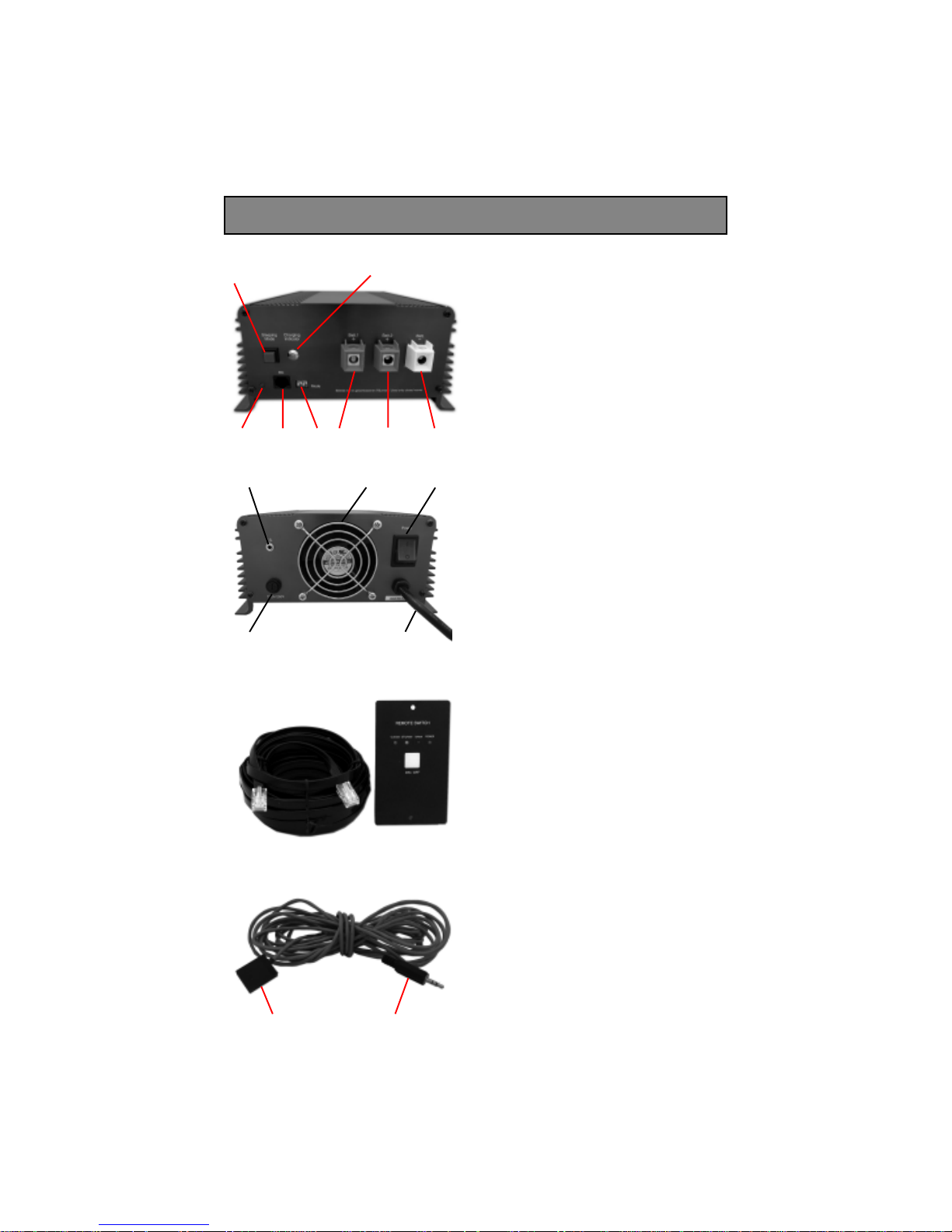
COMPONENTS AND ACCESSORIES
7
53
6812
12
10 13
4
11
1. Output connnector + Bank 1
2. Output Connector + Bank 2
3. Output Connector - Common
4. Charging Indicator LED
5. Dip Switches for mode selection
6. Jack for Remote Panel
7. Push Switch for Mute Mode
8. LED for Mute Mode indication
9
9. AC input Power On / Off Switch
10. AC fuse holder
11. Cooling fan
12. Jack for Temperature Sensor
13. AC power cord inlet
14
16 17
14*. Cable with plug
15*. Remote Panel
(*14 & 15 are optional accessories)
15
16. Temperature sensor element
17. plug
Page 4
Page 6

SPECIFYING LEAD ACID BA TTERIES AND CHARGERS
FLOODED / WET CELL AND SLA (SEALED LEAD ACID) BATTERIES
There are two categories of lead acid batteries – Flooded/Wet Cell and Sealed Lead Acid
(SLA). A flooded/wet cell battery has a high tolerance to overcharging. However, it will
release hydrogen gas when charging that must be properly vented and the water level
must be checked frequently. SLA batteries can either be Gel Cell or AGM (Absorbed
Glass Mat). Both the Gel Cell and AGM are maintenance free, have no liquid to spill and
gassing is minimal. The Gel Cell is the least affected by temperature extremes, storage at
low state of charge and has a low rate of self discharge. An AGM battery will handle
overcharging slightly better than the Gel Cell
Lead-acid batteries can be categorized by the type of application: automotive service -
Starting/Lighting/Ignition (SLI, a.k.a. cranking) and Deep Cycle service
SLI BATTERIES
Everybody is familiar with the SLI batteries that are used for automotive starting and
powering vehicular accessories. SLI batteries are designed to produce high power in short
bursts but must be constantly recharged (normally with an alternator while driving).
Vehicle starting typically discharges 1%-3% of a healthy SLI battery’s capacity.
The automotive SLI battery is not designed for repeated deep discharge where up to 80 %
of the battery capacity is discharged and then recharged. If an SLI battery is used for this
type of application, its useful service life will be drastically reduced
DEEP CYCLE BATTERIES
Deep cycle batteries are designed with thick-plate electrodes to serve as primary power
sources, to have a constant discharge rate, to have the capability to be deeply discharged
up to 80 % capacity and to repeatedly accept recharging. They are marketed for use in
recreation vehicles (RV), boats and electric golf carts – so they may be referred to as RV
batteries, marine batteries or golf cart batteries. There are two categories of deep cycle
lead acid batteries – wet and sealed. A wet cell battery has a high tolerance to overcharging. However, it will release hydrogen gas when charging that must be properly vented
and the water level must be checked frequently. Sealed batteries can either be Gel Cell or
AGM (Absorbed Glass Mat). Both the Gel Cell and AGM are maintenance free, have no
liquid to spill and gassing is minimal. The Gel Cell is the least affected by temperature
extremes, storage at low state of charge and has a low rate of self discharge. An AGM
battery will handle overcharging slightly better than the Gel Cell
Page 5
Page 7

UNITS OF BATTERY CAPACITY
The battery capacity is the measure of the energy the battery can store and deliver to a
load. It is determined by how much current any given battery can deliver over a stipulated period of time. The energy rating is expressed in Ampere Hours (AH). As a bench
mark, the battery industry rates batteries at 20 hour rate i.e. how many Amperes of
current the battery can deliver for 20 hours at 80 º F till the voltage drops to 10.5 Volts
for 12 V battery and 21 V for 24 V battery. For example, a 100 AH battery will deliver 5
Amperes for 20 hours. Battery capacity is also expressed as Reserve Capacity (RC) in
minutes. Reserve capacity is the time in minutes for which the battery can deliver 25
Amperes at 80 º F till the voltage drops to 10.5 Volts for 12 V battery and 21 V for 24 V
battery. Approximate relationship between the two units is as follows:
Capacity in AH = Reserve Capacity in RC minutes x 0.6
TYPICAL BATTERY SIZES
Below is a chart of some battery sizes applicable for powering
inverters:
BCI * Group Battery Voltage, V Battery AH
27 / 31 12 105
4 D 12 160
8D 12 225
GC2** 6 220
* Battery Council International ** Golf Cart
REDUCTION IN USABLE CAPACITY AT HIGHER DISCHARGE RATES.
As stated above, the rated capacity of the battery in AH is applicable at a discharge rate of
20 Hours. As the discharge rate is increased, the usable capacity reduces due to “Peukert
Effect”. This relationship is not linear but is more or less according to the table below:
Table 1 Battery Capacity versus Rate of Discharge
Hours of Discharge Usable Capacity
20 100%
10 87%
8 83%
6 75%
5 70%
3 60%
2 50%
1 40%
Using the above table will show that a 100 AH capacity battery will deliver 100% (i.e.
full 100 AH) capacity if it is slowly discharged over 20 hours at the rate of 5 Amperes.
However, if it is discharged at a rate of 50 Amperes then theoretically, it should provide
100 AH ÷ 50 = 2 hours. However, the Table above shows that for 2 hours discharge rate,
the capacity is reduced to 50% i.e. 50 AH. Therefore, at 50 Ampere discharge rate the
battery will actually last for 50 AH÷50 Amperes = 1 Hour
Page 6
Page 8

DEPTH OF DISCHARGE AND BATTERY LIFE
The more deeply a battery is discharged on each cycle, the shorter the battery life. Using
more batteries than the minimum required will result in longer life for the battery bank. A
typical cycle life chart is given at Table 2 below:
Table 2. – Typical Cycle Life Chart
Depth of Discharge Cycle Life Cycle Life Cycle Life
% of AH Capacity Group 27 / 31 Group 8D Group GC2
10 1000 1500 3800
50 320 480 1100
80 200 300 675
100 150 225 550
It is recommended that the depth of discharge should be limited to 50 %
LOSS OF BATTERY CAPACITY AT LOW TEMPERATURES.
Batteries lose capacity in low temperatures. At 32 º F, a battery will deliver about 70 to
80 % of its rated capacity at 80 º F. If the air temperature near the battery bank is lower
than 80 º F, additional batteries will be needed to provide the same usable capacity. For
very cold climates, an insulated / heated battery compartment is recommended.
SERIES AND PARALLEL CONNECTION OF BATTERIES AND BATTERY
BANKS
When two or more batteries are
connected in series, their voltages add up but their AH
capacity remains the same. This series connection is also called a “string”. For example,
when two 12 V, 105 AH batteries are connected in series, it becomes a 24 V, 105 AH
battery. (Positive of the first battery is the positive terminal of the series connection. The
negative of the first battery is connected to the positive of the second battery. The
negative of the second battery is the negative of the series connection)
When two or more batteries or battery “strings” are connected in parallel, their voltages
remain the same but their capacities add up. For example, if two 12 V, 105 AH batteries
are connected in parallel, their voltage remains 12 V but their capacity becomes 105 × 2
= 210 AH (Connect the positive terminal of the first battery to the positive terminal of the
second battery. These paralleled common positive terminals become the positive terminal
of the parallel combination. Connect the negative terminal of the first battery to the
negative terminal of the second battery. These paralleled common negative terminals
become the negative terminal of the parallel combination).
A “bank” of battery may be a single battery or a series / parallel combination of a group
of batteries that is used for a particular DC power system. Two or more independent DC
power systems may use two or more associated independent battery “banks”. For
example, in an RV, one “bank” of battery is used for the vehicle’s Starting , Lighting and
Ignition System. A second “bank” of Deep Cycle Auxiliary Batteries is used for running
other DC loads like inverter etc
Page 7
Page 9

CHARGING BA TTERIES
The batteries can be charged by using good quality AC powered battery charger or from
alternative energy sources like solar panels, wind or hydro systems. Make sure an
appropriate battery charge controller is used. It is recommended that the batteries may
not be charged at current > C/5 (where C is the AH capacity of the battery at 20 hour
discharge rate). Also, for complete charging (return of 100 % capacity ), it is recommended that a 3 stage, temperature compensated charger may be used (Constant current
bulk charging followed by constant voltage boost / absorption charging followed by
constant voltage float charging )
Page 8
Page 10
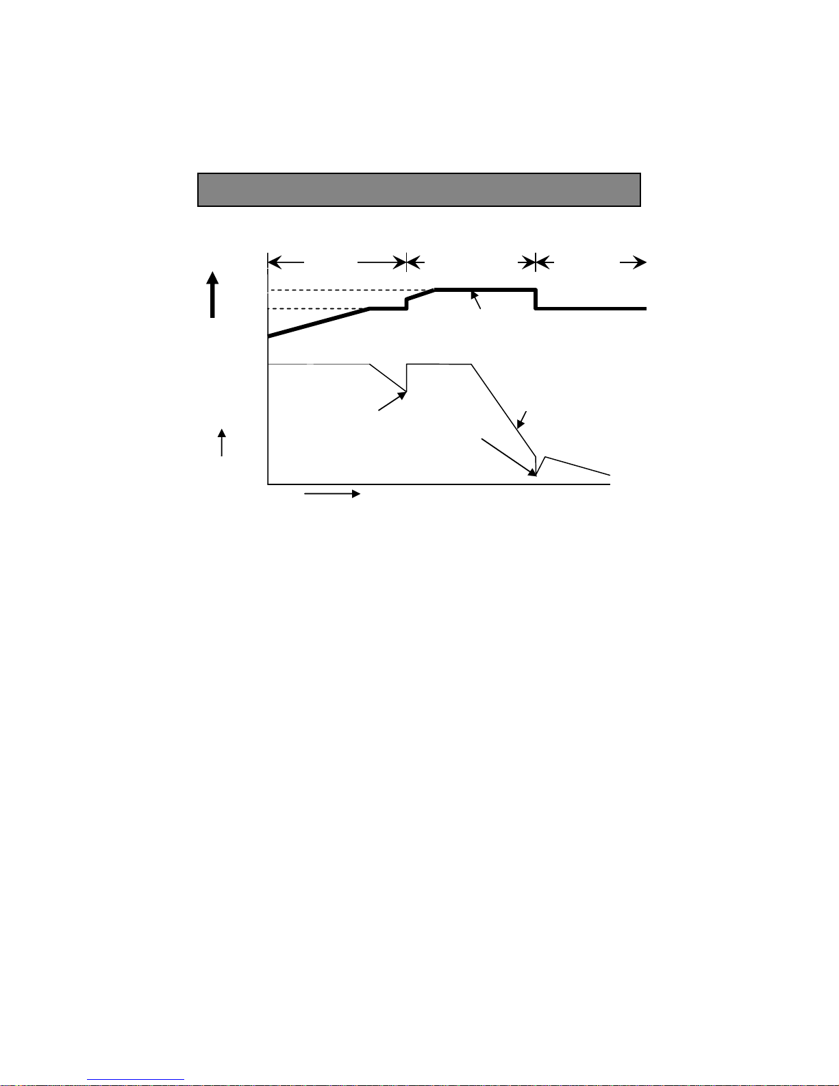
CHARGING STAGES
Stage 1
I Phase
Uo
Stage 2
Uo Phase
Timed for 4 / 8
Hours
Stage 3,
U Phase
U
Voltage V
80% of current
capacity of
charger
Current, I
Time, Hours
Figure 1 Charging Curve
Note! - Voltage reading on no load. The output terminals of the charger consist of one
common white / black negative terminal (3) and two red positive terminals (1, 2) for
charging two banks of batteries. Each of the two positive terminals of the two banks has a
Schottky Diode in series for isolation. These isolating diodes have a current dependent
forward voltage drop ranging from 0.2 to 0.3 V (at 0.1 A) to 0.6 V (at 45 A). Please note
that the forward voltage drop occurs only when current flows through the diode. The
Float and Absorption voltages are tightly regulated before the isolating diodes. However,
the voltages available at the terminals of the two banks will vary with the value of the
charging current because of the current dependent forward voltage drop across the
isolating diodes. The Float and Boost / Absorption voltages before the diodes are,
therefore, set 0.2 to 0.3 V higher to compensate for the above forward drop during float
condition when the charging current would have dropped to less than 1 A. Hence, the
output voltage at the terminals of the two banks at no load (nothing connected to the
terminals of the banks) will read 0.2 to 0.3 V higher because there is no forward voltage
drop as there is no current flow through the diodes. Please also note that the output
voltage at the two banks may differ between 0.2 to 0.6 V depending upon the different
values of the charging current being delivered through each.
Curve for
Voltage U, Uo
Curve for
Current I
10% of current
capacity of
charger
Page 9
Page 11

BATTERY VOLTAGES – CHARGED AND DISCHARGED CONDITIONS
The cell voltage of a battery depends upon the temperature of the battery and has a
negative temperature coefficient – the voltage level increases at lower temperature and
decreases at higher temperature. The voltages are normally specified at 80º F (26.7º C)
On a 12 volt battery, the no load battery voltage is between 11.4 VDC (fully discharged)
and 12.9-13.0 VDC (fully charged). On a 24 volt battery, the no load battery voltage is
between 22.8 VDC (fully discharged) and 25.8 -26.0 VDC (fully charged).
CHARGING STAGES - I, Uo, U
The charger is preset to charge in 3 stages as described in the succeeding paragraphs. The
charger is called “IUoU Charger” based on the DIN designation of the charging stages – I
Phase, Uo Phase and U Phase. Please refer to the charging curve given at Figure 1 for
understanding the 3 charging stages
NOTE: The charging voltages indicated below pertain to battery temperature of 80º F
Stage 1 - Constant Current, Bulk Charge Mode (I Phase): When the charger is first
connected to a battery, the battery will start drawing current proportional to the discharged condition of the battery. When the battery is deeply discharged, it will initially
try to draw a very large current. If this initial current draw is more than 45 A (SEC1245A) or more than 25A (SEC-2425A), the charger will enter Stage 1 – The Bulk
Charge Mode (I Phase). During this period, SEC-1245A will deliver a constant current I
= 45 A and SEC-2425A will deliver a constant current I = 25 A. The charger will be
operating under current limit condition and the voltage at the charging terminal will be
same as the actual voltage of the discharged battery. The voltage of the battery will
slowly start rising and when the battery voltage approaches voltage U = 13.8 V (SEC1245A) or voltage U = 27.6 V (SEC-2425A), the current drawn by the battery will
reduce below the current limit value of 45 A (SEC-1245A) and 25 A (SEC-2425A). The
charger will exit current limit condition and will now output constant voltage of U = 13.8
V (SEC-1245A) or constant voltage U = 27.6 V (SEC-2425A). The battery will continue
to charge at this constant voltage and its charging current draw will reduce further. When
the charging current drawn by the battery reduces below 80% of the charger capacity “I”
i.e. 36 A (for SEC-1245A) or 20 A (for SEC-2425A), the charger will automatically
switch over to Stage 2 – Constant Over-voltage, Timed Absorption / Boost Charge Stage
(Uo Phase).
During this Stage, following LED indications are provided:
• Charging Indicator LED (4) on the front panel turns red
• Red LED under “I Phase” is lighted on the Remote
Panel (15) ( Optional accessory)
Note: When Mute Mode is selected (See under “Mute Mode / Reduction of Maximum
Charging Capacity”), the fan is disabled to cut out fan noise for a quiet operation. To
reduce heat dissipation during the Mute Mode, the maximum charging capacity (current
limit value) of the charger is reduced as follows:
• Current limit of SEC-1245A is reduced to 16 – 18 A
instead of 45 A
• Current limit of SEC-2425A is reduced to 8 A to 10 A
instead of 25 A
Page 10
Page 12

Stage 2 - Constant Overcharge Voltage, Timed Absorption / Boost Charge Mode (Uo
Phase): When the charger enters Stage 2 from Stage 1, the battery is approximately 70%
to 80% recharged. As soon as it enters this stage, a timer circuit is also initiated. The
timer circuit can be selected to operate for 4 or 8 hours with the help of Dip Switches (5)
(See under “Selecting time for Absorption / Boost Stage”). During this stage, the charger
will output a higher constant overcharge voltage whose value will depend upon the type
of battery or charging stages selected ( The type of battery and charging stages are
selected with the help of Dip Switches (5) – See under “Selecting The Type of Battery
and Charging Stages”)
• 14.4 V (SEC-1245A) or 28.8 V (SEC-2425A) when Flooded / AGM battery is
selected
• 14 V (SEC-1245A) or 28 V (SEC-2425A) when Gel Cell battery is selected
• 13.5 V (SEC-1245A) or 27 V (SEC-2425A) when loaded battery is selected (2
stage charging)
The battery will further absorb charge at this voltage and the charging current will further
reduce. When the charging current reduces to approximately 10% of the charger capacity
“I” (10 % of 45 A = 4.5 A for SEC-1245A and 10% of 25 A = 2.5 A for SEC-2425A), the
charger automatically transitions to “Stage 3 - Float / Maintenance Charge Mode (U
Phase)”. However, if the charging current does not reduce to the above threshold level
(because of some defective / shorted cells or due to an external load in a loaded battery),
the charger will be forced to change-over to “Stage 3 or Float / Maintenance Charge
Mode (U Phase)” after elapse of 4 or 8 hours determined by the selected duration of the
timer circuit. The battery will be charged to approx. 95% of its capacity by the end of this
stage. Ideally it would be at 100%, but there are some practical limitations like temperature effect etc that usually prevent full recharge.
During this Stage, following LED indications are provided:
• Charging Indicator LED (4) on the front panel turns orange
• Yellow LED under “Uo Phase” is lighted on the Remote Panel (15) ( Optional
accessory)
Stage 3 – Constant Voltage, Float or Maintenance Charge Mode (U Phase): During
this mode, the charger outputs a constant voltage U = 13.5 V (SEC-1245A) or 27 V
(SEC-2425A). This helps in maintaining full capacity of the battery and also provides
replacement charge to overcome self discharge of the battery. The battery can remain
connected in this stage indefinitely without the risk discharging.
During this Stage, following LED indications are provided:
• Charging Indicator LED (4) on the front panel turns green
• Green LED under “U Phase” is lighted on the Remote Panel (15) ( Optional
accessory)
Page 11
Page 13

CAUTION!
3 stage charging is recommended for charging stand-alone unloaded batteries (there is no
load connected to the battery when it is being charged). If a load is also connected
simultaneously, a part of the charger’s output current will be diverted to this load. Thus,
the charger may remain locked in Stage 2 if the current drawn by the load is more than
the preset value of threshold current determining transition from Stage 2 to Stage 3 .This
will lead to overcharging and loss of electrolyte
For charging a battery when a load is also connected simultaneously, Stage 2 voltage
should be same as Stage 3. Select “Loaded Battery” with the help of Dip Switches (5) –
See under “Selecting the Type of Battery and Charging Stages”
COOLING
The charger is cooled by convection and in addition, has a fan (11) for forced air cooling.
The fan will automatically switch on when the charger enters the Boost / Absorption
Stage 2 (Charging Indicator LED (4) will be Orange) or the Bulk Charging Stage 1
(Charging Indicator LED (4) will be Red). The fan will automatically stop when the
charger enters Float Stage 3 (Charging Indicator LED will be Green). Please note that the
fan will be off in the Float Stage 3 (The Charging Indicator LED will be Green).
The fan will generate audible noise when it is on. If a quiet operation is required, the fan
can be temporarily disabled by pressing the “Mute Mode” push switch.
switched off during the “Mute Mode”, the current output during this mode will be
automatically reduced (16 to 18 A for SEC-1245A and 8 to 10 A for SEC-2425A) to limit
the temperature rise. Please see details under “Mute Mode / Reduction of Maximum
Charging Capacity”
As the fan will be
In case the fan fails or if the cooling is not adequate due to higher ambient temperature,
inadequate air circulation or blockage of air ventilation openings, the thermal sensor for
over-temperature protection will shut down the output voltage of the charger. The
Charging Indication LED on the front panel will turn red ( On the Remote Panel, the red
LED “I Phase” will light, the green LED “Power” will, however, remain lighted). The
charger will be latched in this shut down condition and will not reset automatically even
after the unit has cooled down. To reset, the AC input power on / off switch (9) at the
back of the unit has to be switched off and on again.
Page 12
Page 14

PROTECTION
The charger has the following protections:
SHORT CIRCUIT SHUT DOWN
In case of a short circuit on the output side, the output of the charger will be shut down.
The Charging Indication LED (4) on the front panel will turn red (On the Remote Panel
(15), the red LED “I Phase” will light, the green LED “Power” will, however, remain
lighted). The charger will be latched in this shut down condition and will NOT recover
automatically even after the short circuit condition is removed.
power on / off switch (9) at the back of the unit has to be switched off and on again.
OVER LOAD CURRENT LIMITING
The current drawn by the load is automatically limited to a maximum of 45 A for SEC1245A (16 A to 18 A when in “Mute Mode”) and 25 A for SEC-2425A (8 A to 10 A in
“Mute Mode”). If the load tries to draw a higher current than these limits, the output
voltage of the unit will start to drop. The unit will automatically recover when the
overload condition is removed
REVERSE BATTERY CONNECTION CUT OFF
The output is internally fused on the DC side – 2 x 30 A fuses for SEC-1245A and 2 X 20
A fuses for SEC-2425A. In case, the polarity of the battery connection is reversed, the
fuse(s) will blow. The Charging Indication LED (4) on the front panel will turn red (On
the Remote Panel (15), the red LED “I Phase” will light, the green LED “Power” will,
however, remain lighted). The fuse(s) will be required to be replaced for the unit to
function again
To reset, the AC input
THERMAL OVERLOAD SHUTDOWN
Caution
vent holes on the sides or the discharge openings of the cooling fan
In case the fan fails or if the cooling is not adequate due to higher ambient temperature,
inadequate air circulation or blockage of air ventilation openings, the thermal sensor for
over-temperature protection will shut down the output voltage of the charger. The
Charging Indication LED (4) on the front panel will turn red (On the Remote Panel (15),
the red LED “I Phase” will light, the green LED “Power” will, however, remain lighted).
The charger will be latched in this shut down condition and will NOT reset automatically
even after the unit has cooled down.
the back of the unit has to be switched off and on again.
PROTECTION AGAINST TRANSIENTS / SURGES IN THE AC INPUT
In a number of locations, the AC line input is not clean and may contain high voltage
transients / surges. To prevent damage to the internal components against these unwanted
high voltages, the charger uses MOV (Metal Oxide Varistor) for protection. If surge /
transient voltage higher than approximately 170 VAC appear in the AC input, the MOV
will conduct and will blow the AC side fuse.
! Keep the charger in a well ventilated, cool and open area. Do not block the
To reset, the AC input power on / off (9) switch at
Page 13
Page 15

INSTALLATION
LOCATION, MOUNTING AND SAFETY
The charger is required to be installed in a safe, well ventilated and dry location. Please
see the details given under “Important Safety Precautions”
The charger can be mounted horizontally or vertically. When mounting vertically, please
ensure that the axis of the fan rotor is horizontal (to reduce stress on the bearing)
OUTPUT CONNECTORS
Connectors with tubular, screw down type of terminals are used for output connection.
The diameter of the tubular hole of the connector is 8 mm (0.31 inches).
Two positive output connectors (1, 2) are provided for connecting to the positive
terminals of the 2 banks of batteries. One common connector (3) is provided for the
negative connection
For firm connection when using stranded cable, crimp / solder “pin” style terminal on the
charger end of the DC cables used for connecting to the battery / other DC loads
CABLES
To avoid polarity errors and possible damage, never use cables of only one color. Use red
insulated cable(s) for positive connection(s) and black for negative connection(s)
Recommended DC cable sizes are given below (Based on a voltage drop of 2%). The
length in feet is the length of the pair of the positive and negative DC cables from the
charger to the battery / other DC loads
Distance from battery SEC-1245A SEC-2425A
Up to 6 ft. AWG # 6 AWG # 8
6 to 10 ft AWG # 4 AWG # 6
10 to 20 ft. AWG # 2 AWG # 4
Page 14
Page 16

PREPARING THE CHARGER FOR OPERATION
AC INPUT CONNECTION
The charger is
provided with a 6 ft attached cord with molded NEMA5-15P plug. Please ensure that the
AC outlet is 2 pole, 3 wire grounding type – “NEMA5-15R”
CONNECTING THE BATTERIES OR OTHER DC LOADS
The output of the charger has a common Negative (-) connector (3) and 2 Positive
connectors (1, 2) for connection of 2 banks of batteries. Each Positive connector has its
own internal isolating diode which works as a battery isolator. If more than one bank of
batteries is connected, these will be charged at the same time as long as the AC power is
available to the charger (the maximum charging current of 45 A of SEC-1245A and 25 A
of SEC-2425A will be shared among the connected banks of
pre-set to operate from input AC voltage of 120 VAC, 60 Hz and is
the batteries depending
upon their discharged states). In case the AC power fails or if there is no output from
the charger, the isolating diodes will prevent charging / discharging among the batteries
connected to the banks.
Caution!
charged, make sure that their negatives are connected to the common negative connector
(3) of the charger and their positives are connected to the same positive connector ( either
1 or 2) of the charger. For example, when charging a bank consisting of 3 batteries
connected in parallel, their 3 negative terminals should be connected to the common
negative terminal (3) of the charger and all their 3 positive terminals should be connected
to the same positive terminal of the charger ( either 1 or 2). Alternatively, the negative
terminals of the 3 batteries should first be shorted and then connected to the common
negative terminal (3) of the charger and similarly, the 3 positive terminals of the battery
should first be shorted and then connected to one of the 2 positive terminals of the
charger (either 1 or 2)
When a single bank consisting of more than one battery in parallel is to be
When connecting a single battery or other DC load, it can be connected to the common
negative (3) and any one of the 2 positive terminals (either 1 or 2)
CHARGING MORE THAN ONE BANK OF BATTERIES
CAUTION! When charging more than one bank of batteries at the same time using 3
Stage Charging
condition. If one bank is completely discharged and another is almost fully charged, the
bank that is fully charged will be subjected to over charge condition during the time
when the charger remains in Stage 2 for charging the completely discharged bank.
If 2 banks of batteries are required to be charged and they are at different discharged
conditions, select “2 Stage Charging” with the help of switches S1 and S2 of the set of 4
Dip Switches (5) (both S1 & S2 in off condition) – See under “Selecting the Type of
Battery and Charging Stages”
, ensure that the batteries in the banks are in a similar discharged
Page 15
Page 17

SELECTING THE TYPE OF BATTERY AND CHARGING STAGES
The Float or Maintenance Charge Mode (U Phase) voltage and Absorption / Boost
Charge Mode (Uo Phase) voltage of different types of Lead Acid Batteries are different.
3 Stage charging (Stages 1, 2 and 3) is recommended when charging stand alone,
unloaded battery (The battery has no load connected to it when it is being charged).
When the charger is used to charge a battery and simultaneously supply an external load,
the voltage level of Stage 2 is required to be set to the same level as the voltage of Stage
3 to prevent over-charging. Effectively, the battery will be charged in 2 stages only –
Stage 1 and Stage 3. This also applies when two banks of batteries are being charged
simultaneously and the batteries in the two banks are in a dissimilar state of discharge
A pair of switches S1 & S2 out of a set of 4 Dip Switches (5) has been provided for
selecting the battery type and for modifying the Boost Stage when charging loaded
batteries / two banks of batteries with different discharged states. The following selections can be made with the help of the Dip Switches S1 and S2:
Caution!! :
Do not change the Dip Switch setting when the charger is operating. Always
change the Dip Switch setting when the charger is off, i.e. after disconnecting the charger
from the AC input power)
NOTE:
The voltages are for battery temperature of 80º F
DIP Switch Setting for SEC-1245A
S1 S2 Float Boost Battery Type Charging Stages
Stand-alone charging
OFF * ON * 13.5 V * 14.4 V * Flooded / AGM * 3 Stages (Stages 1, 2, 3)
ON OFF 13.5 V 14.0 V Gel Cell 3 Stages (Stages 1, 2, 3)
Charging loaded battery
or
Charging two banks and the batteries in the two banks are in dissimilar discharged
condition
OFF OFF 13.5 V 13.5 V Flooded / AGM / Gel 2 Stages (Stages 1, 3)
* Factory pre set in this position
Page 16
Page 18

DIP Switch Setting for SEC-2425A
S1 S2 Float Boost Battery Type Charging Stages
Stand-alone charging
OFF * ON * 27 V * 28.8 V * Flooded / AGM * 3 Stages (Stages 1, 2, 3)
ON OFF 27 V 28.0 V Gel Cell 3 Stages (Stages 1, 2, 3)
Charging loaded battery
or
Charging two banks and the batteries in the two banks are in dissimilar discharged
condition
OFF OFF 27 V 27.0 V Flooded / AGM / Gel 2 Stages (Stages 1, 3)
* Factory pre set in this position
Caution!
Please ensure that position S1- ON and
S2 – ON is never selected
SELECTING THE TIME FOR STAGE 2 - CONSTANT OVERCHARGE VOLTAGE, TIMED ABSORPTION / BOOST CHARGE MODE (Uo PHASE)
Stage 2 - Constant Overcharge Voltage, Timed Absorption / Boost Charge Mode (Uo
Phase) is controlled by an internal timer circuit. Time of 4 hours or 8 hours can be
selected with the help of a pair of switches S3 & S4 of the set of 4 Dip Switches (5).
Select the times as follows:
Time Dip Switch S3 Dip Switch S4 Type of Battery
4 hours* Off* On* Flooded / wet cell
8 hours On Off Gel Cell & AGM
Disable Off Off -
* Factory pre set in this position
Caution!
Please ensure that position S3- ON and
S4 – ON is never selected
MUTE MODE / REDUCTION OF MAXIMUM CHARGING CAPACITY
Switching off the cooling fan to eliminate fan noise for quiet operation
The cooling fan automatically switches on when the charger enters Stage 2. The fan will
generate noise when it is on. If a quiet operation is required, the fan can be temporarily
disabled by pressing the “Mute Mode” push switch (7). As the fan will be switched off
during the “Mute Mode”, the current output during this mode will be automatically
reduced to 16 to 18 A for SEC-1245A and 8 to 10 A for SEC-2425A to limit the temperature rise.
When the Mute Mode function is selected, a Green LED (8) located on the bottom left
corner of the front panel of the unit is lighted
Page 17
Page 19

Reducing Maximum Charging Current Capacity to Charge Lower Capacity Batteries
“Mute Mode” can also be selected to reduce the maximum charging capacity to approximately 1/3 of rated capacity of the charger. This can be used to safely charge lower
capacity batteries
Batteries should not be charged at very high currents to ensure long life. Normally, the
maximum charging current should be limited to approximately C/5 (where C is the AH
capacity of the battery at 20 hour rate). Thus, at the rated current capacities (45 A for SEC1245A and 25 A for SEC-2425A), the minimum AH capacity of the battery that should be
charged with the charger will be:
• 45 A x 5 = 225 AH for SEC-1245A
• 25 A x 5 = 125 AH for SEC-2425A
Thus, SEC-1245A should be used to charge battery with AH capacity > 225 AH and SEC2425A should be used to charge battery with AH capacity > 125 AH
However, when the Mute Mode is selected, the maximum
charging capacity is reduced to approximately 1/3. Hence, when
Mute Mode is selected, it will be possible to also charge lower
capacity batteries as follows;
• SEC-1245A - up to 75 AH ( 225 AH / 3 = 75 AH)
• SEC-2425A - up to 42 AH ( 125 AH / 3 = 42 AH)
TEMPERATURE COMPENSATION
The cell voltages of a battery depend upon the temperature of the cells inside the battery.
The cells have a negative temperature coefficient – their voltage levels increase at lower
temperature and decrease at higher temperature. The negative temperature coefficient is –
2.8 mV / º F / cell or - 16.8 mV / º F/ 6 cells for a 12 V battery or - 33.6 mV / º F / 12 cells
for a 24 V battery.
The battery and battery charger voltages are normally specified at a temperature of 80 º F
(26.7 º C). Thus, if the battery temperature is considerably lower than or higher than 80 º F,
it will be under-charged or over-charged unless the battery charger has temperature
compensation.
TEMPERATURE SENSOR PROBE TF-500
This charger has a provision for temperature compensation. A temperature sensor unit Model No. TF-500 (16, 17) is provided for this purpose.
CAUTION! This temperature sensor is matched and calibrated for each battery charger
and should not be interchanged with the sensor from another battery charger
The temperature sensor comes with 5 Metre cable. It has a plug (17) on one end. Connect
this plug into the jack marked TS (12) on the rear panel of the charger. The other end has
the temperature sensor element (16). Mount this temperature sensor element flush with the
top surface of the battery for proper heat transfer
When the temperature sensor is connected, the voltages during Stage 2 and Stage 3 are
automatically adjusted as per the temperature of the battery and the above temperature
coefficient
Page 18
Page 20

REMOTE PANEL - MODEL NO. 900-RC
An optional wired Remote Panel Model No. 900-RC (15) can be ordered. It comes with
10 metres of flat ribbon cable (14) that has 8 position modular male connector on either
end.
The Remote Panel (15) can be used to switch on / switch off the charger and also monitor
the charging status of the charger from a remote location.
CONTROLS AND INDICATIONS
The Remote Panel has the following controls / indications:
• Keypad switch for switching on and switching off
• Red LED under “I Phase”
• Yellow LED under “UoPhase”
• Green LED under “U Phase”
• Green LED under “Power”
CONNECTION
To connect the Remote Panel to the charger, insert one connector of the flat ribbon cable
(14) into the modular jack on the Remote Panel (15) and the other connector to the
modular jack (6) on the charger.
OPERATION
The charger should be first switched on with the help of the AC input power on / off
switch (9) located on rear panel of the charger.
The charger can now be switched on and off with the help of the keypad switch on the
Remote Panel (15)
INDICATIONS
Whenever the charger is switched on, the Green LED “Power” will be lighted. The other
LEDs indicate the charging status as follows:
• Red LED “I Phase” is lighted – Indicates that charger is in Stage 1 - Constant
Current, Bulk Charge Mode (I Phase) and is delivering 45 A to 36 A (SEC1245A) or 25 A to 20 A (SEC-2425A)
• Yellow LED “Uo Phase” is lighted – Indicates that the charger is in Stage 2 –
Constant Overcharge Voltage, Timed Absorption / Boost Charge Stage ( Uo
Phase) and is delivering between 36 A to 4.5 A (SEC-1245A) or between 20 A
to 2.5 A (SEC-2425A)
• Green LED “U Phase” is lighted – Indicates that the charger is in Stage 3 Constant Voltage, Float or Maintenance Charge Mode (U Phase). The charger
is delivering
< 4.5 A (SEC-1245A) or < 2.5 A (SEC-2425A). The battery is fully charged.
Page 19
Page 21

OPERATION
SWITCHING ON / OFF
The charger is switched on /off with the illuminated AC input power on / off switch (9)
located on the rear panel of the unit. The switch is illuminated red when switched on.
INDICATION OF NORMAL OPERATION AND CHARGING STATUS
When the charger is switched on without any load, the Charging Indicator LED (4) on
the front panel turns red, orange and then green. The fan (11) will come on momentarily
and switch off. If a Remote Panel is connected, its green LED “Power” will light and the
other 3 LEDs will light in sequence - I Phase (red), Uo Phase (yellow) and then U Phase
(green)
If a battery or load is connected, the colour of the Charging Indicator (4) on the front
panel will indicate the charging status as follows:
• Charging Indicator LED (4) on the front panel is red – Indicates that
charger is in Stage 1 - Constant Current, Bulk Charge Mode (I Phase) and is
delivering 45 A to 36 A (SEC-1245A) or 25 A to 20 A (SEC-2425A).
• Charging Indicator LED (4) on the front panel is orange – Indicates that the
charger is in Stage 2 – Constant Overcharge Voltage, Timed Absorption / Boost
Charge Stage ( Uo Phase) and is delivering between 36 A to 4.5 A (SEC1245A) or between 20 A to 2.5 A (SEC-2425A)
• Charging Indicator LED (4) on the front panel is green – Indicates that the
charger is in Stage 3 - Constant Voltage, Float or Maintenance Charge Mode (U
Phase). The charger is delivering < 4.5 A (SEC-1245A) or < 2.5 A (SEC2425A). The battery is fully charged. When the battery is fully charged, it
will draw very low current to compensate for its self discharge.
Page 20
Page 22

CHARGING A BATTER Y INSTALLED IN A VEHICLE
Follow these steps when the battery is installed in a vehicle. A spark near a battery may
cause battery explosion. For safety and to reduce the risk of spark near the battery:
1. Position AC and DC cords to reduce risk of damage by hood, door or moving
engine parts
2. Stay clear of fan blades, belts, pulleys and other parts that can cause injury to
persons
3. Check the polarity of the battery posts. A positive ( Pos, P, + ) battery post
usually has a larger diameter than a Negative (Neg, N, - ) post
4. Determine which post of the battery is grounded (Connected) to the chassis
(Engine Block). If the negative post is grounded to the Engine Block (As in
most vehicles), see sub paragraph 5. If the positive post is grounded, see sub
paragraph 6
5. For a negative grounded vehicle, connect the positive (red) DC cable from the
charger to the positive of the battery post. Connect the negative (black) DC
cable from the charger to a section of heavy gauge metal part of the frame or
engine block which is
away from battery. Do not connect to carburetor, fuel
lines or sheet metal body parts.
6. For a positive grounded vehicle, connect the negative (black) DC cable from
the charger to the negative of the battery post. Connect the positive (red) DC
cable from the charger to a section of heavy gauge metal part of the frame or
engine block which is away from battery. Do not connect to carburetor, fuel
lines or sheet metal body parts.
7. Connect the charger AC power cord to the AC outlet
8. When disconnecting the charger, turn switches to off, disconnect AC power
cord, remove connection from the vehicle chassis and then remove connection
from the battery terminal
CHARGING A BATTERY OUTSIDE THE VEHICLE
Follow these steps when the battery is outside the vehicle. A spark near the battery may
cause battery explosion. For safety and to reduce risk of spark near the battery, connect
the charger as follows:
1. Check the polarity of the battery posts. A positive ( Pos, P, + ) battery post
usually has a larger diameter than a Negative ( Neg, N, - ) post
2. Attach a piece of at least 3” of AWG #6 insulated battery cable to the negative
battery post
3. Connect the positive (red) DC cable from the charger to the positive battery
post
4. Position yourself and the free end of the piece of cable attached to the negative
post as far away from the battery as possible and then connect the negative
(black) DC cable from the charger to the free end of the piece of cable attached
to the negative battery post
5. Do not face the battery when making the final connection
6. Connect the charger AC power cord to the AC outlet
7. When disconnecting the charger, always do so in reverse sequence of connecting procedure and break the first connection while standing as far away from
the battery as practical
Page 21
Page 23

POWERING OTHER DC LOADS
The charger can be used as a power supply or as a DC UPS (DC Un-interruptible Power
Supply. For both these applications, first set switches S1 and S2 of Dip Switch (5) to off
position to set the charger to work in 2 stage mode (See under “Selecting the Type of
Battery and Charging Stages”)
USING THE CHARGER AS A POWER SUPPLY: To use as a power supply, first switch off
the DC load. Connect the DC load between the common negative terminal and one of the
2 positive terminals (either 1 or 2). Ensure that the maximum current drawn by the DC
load is below the maximum current rating of the charger. Switch on the charger and then
the DC load
USING THE CHARGER AS A DC UPS: In a DC UPS (Un-interruptible Power Supply) ,
the charger simultaneously powers the DC load as well as the battery. As long as the AC
power to the charger is available and the charger is working normally, the charger will
supply the DC load as well as charge / float the battery. In case the AC power fails or if
the charger stops working, the battery will automatically power the DC load. As soon as
the AC power to the charger is restored, the DC load will once again be fed by the
charger and at the same time the battery will be recharged.
Caution!! Please ensure that the sum of the current drawn by the DC load and the current
desired for charging the battery is less than the maximum current capacity of the charger
To use as a DC UPS, first switch off the DC load and connect it to the battery. Now
connect the battery to the charger as explained above under “Charging a Battery outside
the Vehicle”.
Switch on the charger and then switch on the DC load
Page 22
Page 24

TROUBLESHOOTING
The symptoms of abnormal operation and the possible cause(s) and remedies are given in
the succeeding paragraphs.
There is no output. The AC power on / off switch (9) does not illuminate when
switched on. The charging indicator LED (4) is off (On the Remote Panel (15), the
Green LED under “Power” is off)
There is no AC input voltage in the outlet: Check that AC power is available in the AC
outlet receptacle and that it is switched on
The AC input side fuse is blown due to:
•
High input voltage - Check that the input voltage is 120 VAC nominal (normal
range is 110 to 125 VAC)
• High voltage transients / surges in the AC input line – Ensure that the AC input
voltage is clean and does not have high voltage transients / surges. Input
voltage surges / transients > 170 VAC will blow the AC side fuse. Use a
suitable AC line conditioner / surge suppressor, if necessary
• The unit has become defective – If fuse is not blowing due to the above two
causes, the unit has become defective. Call Technical Support of assistance
There is no output voltage and the Charging Indicator LED (4) is red (On the
Remote Panel (15), the Red LED under “I Phase” is lighted, the Green LED under
“Power” is lighted)
The DC side output fuse is blown The DC side fuse will blow if the battery is connected
in wrong polarity. Ensure that the positive battery post is connected to the positive
connector of the charger (either Bank 1 or Bank 2) and the negative battery post is
connected to the negative connector (common) of the charger. Replace the fuse with the
fuse with the proper rating
The battery / DC load is shorted. Check and remove the short circuit. The charger will
latch in the off condition if it was shut down due to short circuit and will NOT re-set
automatically. To re-set, switch off the AC power input on / off switch (9) and switch on
again
Shut down due to high temperature Check that the cooling fan is working, the air vents
are not clogged and the ambient temperature is not very high. The charger will be latched
in this shut down condition and will NOT reset automatically even after the unit has
cooled down. To reset, the AC input power on / off (9) switch has to be switched off and
on
again.
Page 23
Page 25

When the charger is powered and is being used as a DC power supply / UPS, the
output voltage drops when the DC load is switched on or increased.
The charger is being forced into current limit condition The load is trying to draw current
more than the current limit value of the charger – 45 A for SEC-1245A and 25 A for
SEC-2425A (the current limit value is the maximum specified charging Amps). Once the
load current reaches the current limit value, the current limit circuit is activated and the
output voltage drops. Some loads like motors, compressors, incandescent lamps, halogen
lamps, heating elements, relays, coils, capacitors etc. draw very large inrush / starting
currents which may reach up to 10 times their normal operating currents. Ensure that the
starting / inrush current or the maximum operating current of the load is lower than the
current limit value of the charger. Do not use a load that draws more than 45 A for SEC1245A or more than 25 A for SEC-2425A. Once the load current is reduced below the
above limiting values, the charger will recover automatically.
The battery is getting over charged / overheated / loses water or boils
There is an external load connected to the battery when it is being charged 3-stage
charging is recommended for charging stand-alone or unloaded batteries (there is no load
connected to the battery when it is being charged). If a load is also connected simultaneously, a part of the charger’s output current will be diverted to this load. Thus, the
charger may remain locked in Stage 2 if the current drawn by the load is more than the
preset value of threshold current determining transition from Stage 2 to Stage 3 .This will
lead to overcharging, overheating and loss of electrolyte.
For charging a battery when a load is also connected simultaneously, Stage 2 voltage
should be the same as Stage 3 voltage (Stage 2 is disabled). Select “Loaded Battery” with
the help of Dip Switches S1 and S2 of the set of 4 Dip Switches (5) – See under
“Selecting the Type of Battery and Charging Stages”
Two banks of batteries are being charged and the batteries in the two banks are in
dissimilar state of discharge When charging more than one bank of batteries at the same
time using 3 Stage Charging, ensure that the batteries in the banks are in a similar
discharged condition. If one bank is completely discharged and another is almost fully
charged, the bank that is fully charged will be subjected to over charge condition during
the time when the charger remains in Stage 2 for charging the completely discharged
bank.
If 2 banks of batteries are required to be charged and they are at different discharged
conditions, select “2 Stage Charging” with the help of switches S1 and S2 of the set of 4
Dip Switches (5) (both S1 & S2 in off condition) – See under “Selecting the Type of
Battery and Charging Stages”
Page 24
Page 26

The battery is taking excessively long time to fully recharge
or
When the charger is powered and is being used as a DC power supply / UPS, the
output voltage drops at lower DC load currents
The unit is in Mute Mode. (Green LED (8) located on the bottom left corner of the front
panel of the unit is lighted). When this mode is selected, the maximum charging current
will be automatically reduced to 16 to 18 A for SEC-1245A and 5A and 8 to 10 A for
SEC-2425A to limit the temperature rise. Hence, the charging time will increase. Switch
off the Mute Mode if the full rated charging capacity is required
INTERNAL / EXTERNAL FUSE RATINGS
Both the AC input side and DC output side have fuses.
The AC input side fuse is housed in a fuse holder (10) and is located on the rear panel. It
is rated at 250 V, 12 A, Time Delay (Size 5mm x 20 mm, ceramic tube)
The DC side fuses are located inside the unit. To access these
fuses, remove the bottom cover.
These are automotive blade fuses (“Bussmann” Type ATC) rated as follows:
SEC-1245A 2 pieces, each rated at 32 V, 30 A
SEC-2425A 2 pieces, each rated at 32 V, 20 A
Page 25
Page 27

SPECIFICATIONS
PARAMETER SEC-1245A SEC-2425A
Nominal input voltage 120 VAC, 60 Hz 120 VAC, 60 Hz
Input voltage range 110 VAC to 125 VAC 110 VAC to 125 VAC
Output voltage, VDC
- Absorption / boost, Uo* 14.4* V or 14* V or 28.8* V or 28* V or
disabled* disabled*
- Float / maintenance, U* 13.5* V 27.0* V
Maximum charging current, I
- Normal operation 45 A 25 A
- Mute Mode 16 A to 18 A 8 A to 10 A
Duration for Absorption or 4 Hours or 8 Hours 4 Hours or 8 Hours
Boost Stage 2, Uo
T emperature compensation Yes. With sensor TF-500 Yes. With sensor TF-500
Wired Remote Panel(Optional)Yes. With 900-RC Yes. With 900-RC
Cooling By fan By fan
Protections
- Overload Yes Yes
- Short Circuit Yes Yes
- Reverse polarity Yes Yes
- Thermal overload Yes Yes
Output banks 2 2
Output connector Tubular hole (dia 8 mm) Tubular hole (dia 8 mm)
with set screw with set screw
Operating temperature range 0 to 40 C 0 to 40 C
Fuses
- AC input, 5 mmx20 mm 250 V, 12 A 250 V, 12 A
Time Delay
- DC output, Automotive 32 V, 30 A (2 pieces) 32 V, 20 A (2 pieces)
blade type (Bussmann, “ATC”)
Dimensions (L x W x H), mm 330 x 230 x 108 330 x 230 x 108
Weight 5 Kg. 5 Kg.
Notes
* The charging voltages shown are applicable at battery temperature of 80 F
The above specifications are subject to change without notice
Page 26
Page 28

WARRANTY INFORMATION
2 YEAR Limited Warranty
SEC-1245A / SEC-2425A battery chargers manufactured by Samlex America, Inc. ( the
“ Warrantor ” ) are warranted to be free from defects in workmanship and materials under
normal use and service. This warranty is in effect for 2 years from the date of purchase by
the user ( the “ Purchaser ” )
For a warranty claim, the Purchaser should contact the place of purchase to obtain a Return
Authorization Number.
The defective part or unit should be returned at the Purchaser’s expense to the authorized
location. A written statement describing the nature of the defect, the date of purchase, the
place of purchase, and the Purchaser’s name, address and telephone number should also be
included.
If upon the W arrantor’s examination, the defect proves to be the result of defective material
or workmanship, the equipment will be repaired or replaced at the W arrantor’s option without charge, and returned to the Purchaser at the Warrantor’s expense.
No refund of the purchase price will be granted to the Purchaser, unless the Warrantor is
unable to remedy the defect after having a reasonable number of opportunities to do so.
Warranty service shall be performed only by the Warrantor. Any attempt to remedy the
defect by anyone other than the Warrantor shall render this warranty void.
There shall be no warranty for defects or damages caused by faulty installation or hook-up,
abuse or misuse of the equipment including exposure to excessive heat, salt or fresh water
spray, or water immersion.
No other express warranty is hereby given and there are no warranties which extend beyond those described herein. This warranty is expressly in lieu of any other expressed or
implied warranties, including any implied warranty of merchantability, fitness for the ordinary purposes for which such goods are used, or fitness for a particular purpose, or any
other obligations on the part of the Warrantor or its employees and representatives.
There shall be no responsibility or liability whatsoever on the part of the Warrantor or its
employees and representatives for injury to any persons, or damage to person or persons, or
damage to property, or loss of income or profit, or any other consequential or resulting
damage which may be claimed to have been incurred through the use or sale of the equipment, including any possible failure of malfunction of the equipment, or part thereof.
The Warrantor assumes no liability for incidental or consequential damages of any kind.
Page 27
Page 29

Notes
Page 30

Attach receipt
Page 31

SEC1245A / 2425A (Apr. 2006)
Samlex America Inc.
110-17 Fawcett Road
Coquitlam B.C., Canada V3K 6V2
e-mail: [email protected]
website: www.samlexamerica.com
 Loading...