

Page 1

Remote Control for
EvolutionTM Series
Inverter/ Charger
Model: EVO-RC-PLUS
Please read this
manual BEFORE
operating.
Owner's
Manual
NOTE: REMOTE CONTROL MODEL NO. EVO-RC-PLUS IS OPTIONAL AND IS REQUIRED TO BE ORDERED SEPARATELY.
Page 2

EVO-RC OWNER'S MANUAL | Index
SECTION 1
Introduction and Layout ........................................................ 3
SECTION 2
Installation ........................................................................... 6
SECTION 3
Operation .......................................................................... 8
SECTION 4
Parameter Setup ................................................................ 27
SECTION 5
SD Card ......................................................................... 77
SECTION 6
Monitoring of Operation Using LED and Buzzer ................ 83
SECTION 7
Fault Messages and Troubleshooting Guide ....................... 84
SECTION 8
Specications ..................................................................... 87
SECTION 9
Warranty ......................................................................... 88
Disclaimer of Liability
UNLESS SPECIFICALLY AGREED TO IN WRITING, SAMLEX AMERICA INC:
1. MAKES NO WARRANTY AS TO THE ACCURACY, SUFFICIENCY OR SUITABILITY OF ANY TECHNICAL OR OTHER INFORMATION PROVIDED IN ITS MANUALS OR OTHER DOCUMENTATION.
2. ASSUMES NO RESPONSIBILITY OR LIABILITY FOR LOSSES, DAMAGES, COSTS OR EXPENSES, WHETHER SPECIAL, DIRECT, INDIRECT,
CONSEQUENTIAL OR INCIDENTAL, WHICH MIGHT ARISE OUT OF THE USE OF SUCH INFORMATION. THE USE OF ANY SUCH INFORMATION WILL BE ENTIRELY AT THE USERS RISK.
Samlex America Inc. reserves the right to revise this document and to periodically make changes to the content
hereof without obligation or organization of such revisions or changes.
Copyright Notice/Notice of Copyright
Copyright © 2016 by Samlex America Inc. All rights reserved. Permission to copy, distribute and /or modify this document is prohibited without express written permission by Samlex America Inc.
Page 3
SAMLEX AMERICA INC. | 3
1.0 INTRODUCTION
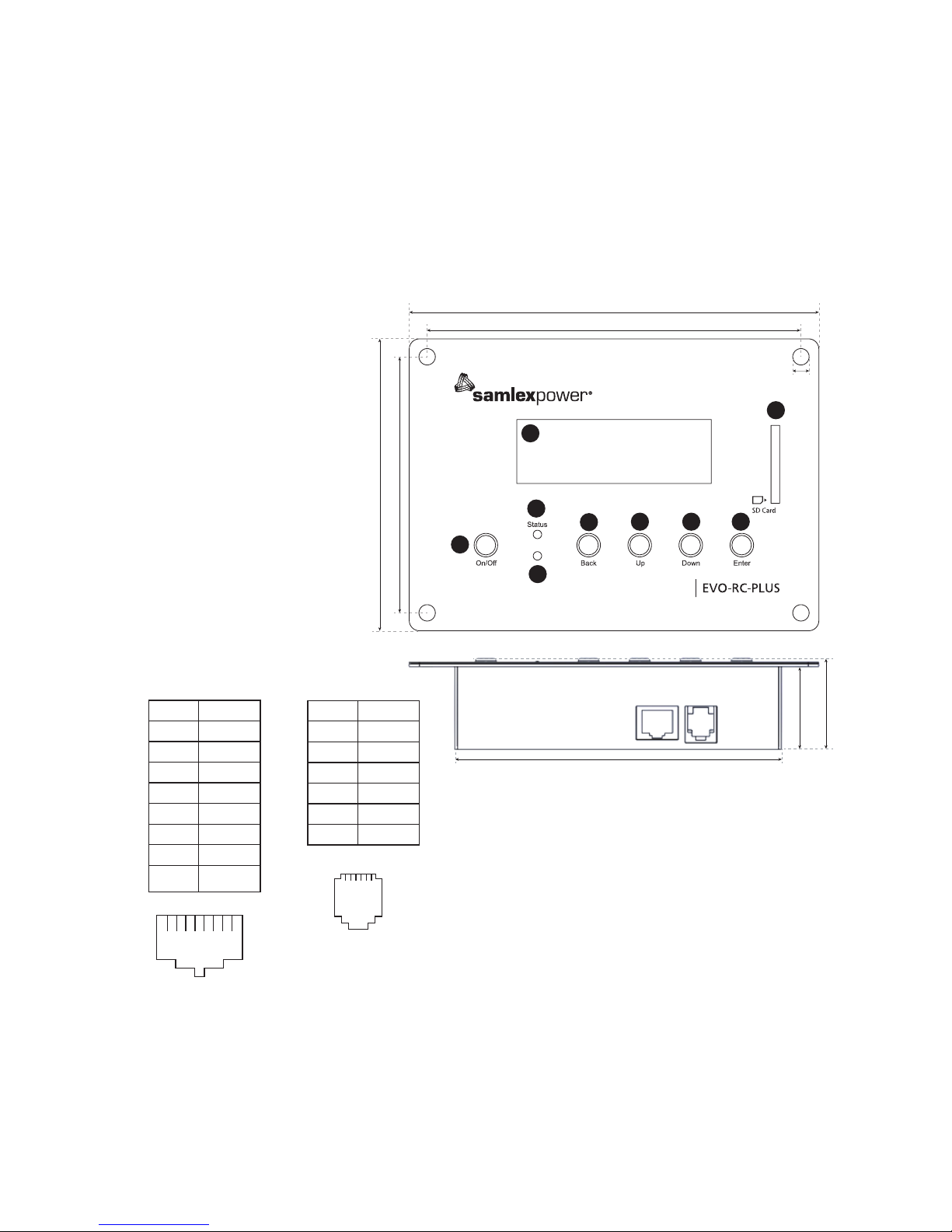
The EVO-RC-PLUS Remote Control allows you to monitor and customize the operating parameters of Samlex EVOTM Inverter/Chargers Models EVO-1212F / 1212F-HW, 1224F / 1224FHW, 2212, 2224, 3012 and 4024. Layout is shown in Fig 1 below.
It has its own internal Real Time Clock and Super Capacitor Type of Battery for clock operation.
1.1 LAYOUT AND DIMENSIONS
Fault
160
114.2
146
4.2
100
Fig 1.1 Layout and dimensions of
Remote Control Model EVO-RC PLUS
9
5
3
4
6
7
8
1
10 11
2
128
32.5
35.5
SECTION 1 | Introduction and Layout
1. LCD Screen:
- 4 rows of 20 characters each
- Blue screen with white
characters
2. ON/OFF Key
3. Blue LED “Status”
4. Red LED “Alarm”
5. Navigation Key “Back”
6. Navigation Key “Up”
7. Navigation Key “Down”
8. Navigation Key “Enter”
9. SD Card Slot – FAT16/32
format, up to 16 GB
10. RJ-45 Jack
Pin # Signal
1 12V
2 12V
3 ON/OFF
4 D+
5 D6 NC
7 GND
8 GND
11. RJ-12 Jack
Pin # Signal
1 NC
2 GND
3 D4 D+
5 12
6 ON/OFF
1.2 CONNECTING CABLE
Details of connecting cable provided with the Remote Control are as follows:
• Length: 10m / 33ft
• No of conductors: 8
• Modular Plug: 8P8C, RJ-45
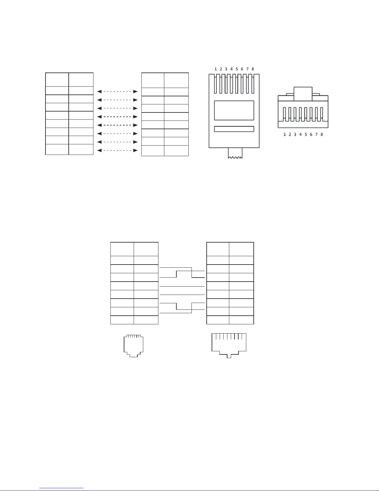
• Plug interconnection: Straight (See Pinout at Fig 1.2)
1 2 3 4 5 6 7 8
12 34 56
12 34 56
View - Looking into the Jack)
View - Looking into the Jack)
Page 4
4 | SAMLEX AMERICA INC.
SECTION 1 | Introduction and Layout
1.3 PINOUT DIAGRAMS & INTERNAL INTERCONNECTION OF RJ-45 &
RJ-12 JACKS
RJ-45 Jack (10, Fig 1.1) and RJ-12 Jack (11, Fig 1.1) are internally connected as pinout at Fig 1.3.
RJ-45
Pin # Signal
1 12V
2 12V
3 ON/OFF
4 D+
5 D6 NC
7 GND
8 GND
Pin Out of
Plug - End 1
RJ-45
Pin # Signal
1 12V
2 12V
3 ON/OFF
4 D+
5 D6 NC
7 GND
8 GND
Pin Out of
Plug - End 2
Top view of Plug -
Locking Tab facing down
Front view of Plug -
Locking Tab
facing up
Fig 1.2 Pin Out of Plugs for 8P8C, RJ-45 Connecting Cable
8P 8C, RJ-45 Modular Plug
RJ-12
Pin # Signal
6 ON/OFF
5 12V
4 D+
3 D2 GND
1 NC
RJ-45
Pin # Signal
1 12V
2 12V
3 ON/OFF
4 D+
5 D6 NC
7 GND
8 GND
Fig 1.3 Pinout and internal interconnections of RJ-45
and RJ-12 (6P6C) Jacks on EVO-RC-PLUS
Straight
Connection
1 2 3 4 5 6 7 8
12 34 56
12 34 56
RJ-12 (6P6C) Jack RJ-45 (8P8C) Jack
Page 5
SECTION 1 | Introduction and Layout
“B-6P4C”“A”
1 2 3 4 5 6 1 2 3 4 5 6
Black
Red
Green
Yellow
6P4C Modular Plug
(Locking Tab
Facing Down)
NC Not connected
6P4C Modular Plug
(Locking Tab
Facing Down)
NC 1
GND 2
D– 3
D+ 4
+12V 5
NC 6
1 NC
2 +12V
3 D+
4 D–
5 GND
6 NC
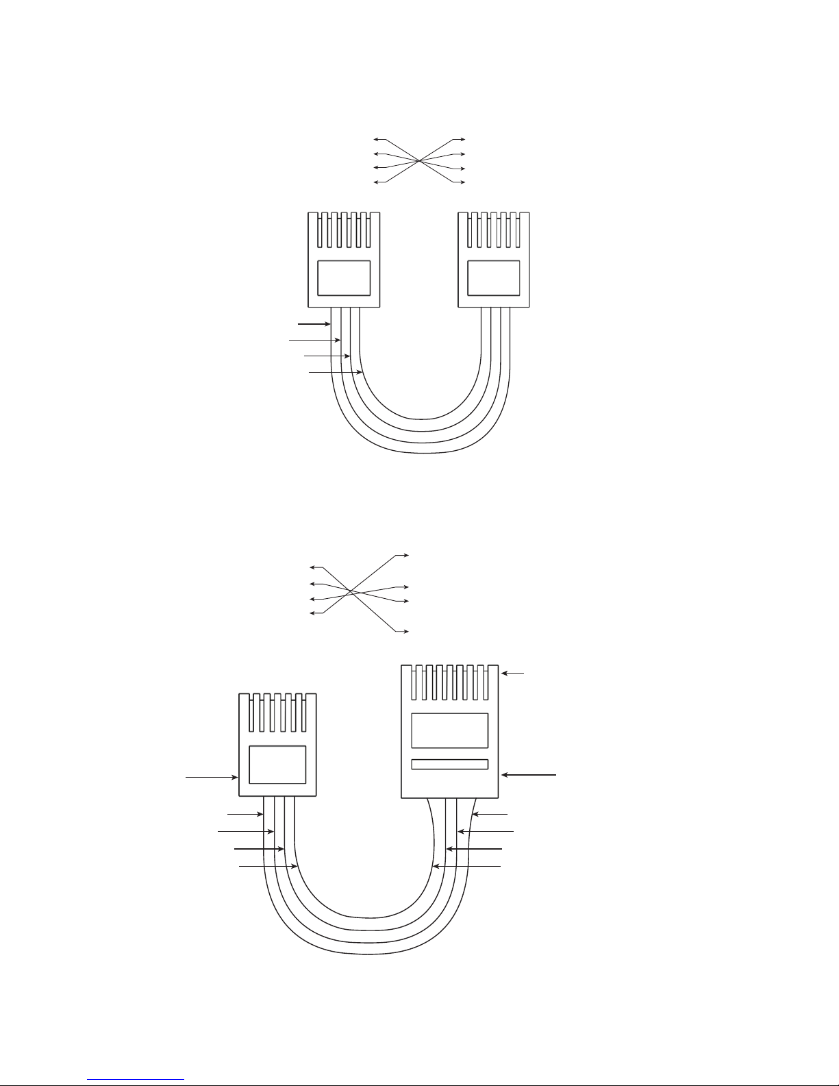
Fig 1.4 RJ-11 (6P4C) cross connected cable
“B-8P8C”
“A”
1 2 3 4 5 6 1 2 3 4 5 6 7 8
Black
Red
Green
Yellow
Black
Red
Green
Yellow
NC Not connected
NC 1
GND 2
D– 3
D+ 4
+12V 5
NC 6
1 NC
2 +12V
3 NC
4 D+
5 D–
6 NC
7 GND
8 NC
* Rewired 8P8C Plug
(Locking tab facing down)
* 6P4C Plug “B-6P4C” of
Fig 1.4 has been cut and
replaced with 8P8C plug
and rewired as shown
Connect to RJ-45 Jack
marked “Remote Control”
on EVO-2212/3012/2224/4024
or EVO-1212F/1212F-HW/
1224F/1224F-HW
Existing 6P6C
Modular Plug
(Locking tab
facing down)
[Fig 1.4]
Connect to
6P6C Jack on
EVO-RC-PLUS
Fig 1.5 RJ-11 (6P4C) cable [Fig 1.4) rewired on one end with RJ-45 (8P8C) Modular Plug
Page 6
6 | SAMLEX AMERICA INC.
SECTION 2 | Installation
2.0 INSTALLATION GUIDELINES
EVO-RC-PLUS is provided with 10M/33ft, RJ-45 data cable (straight wired). Check the proposed
routing distance of the wire and use longer wire, if necessary.
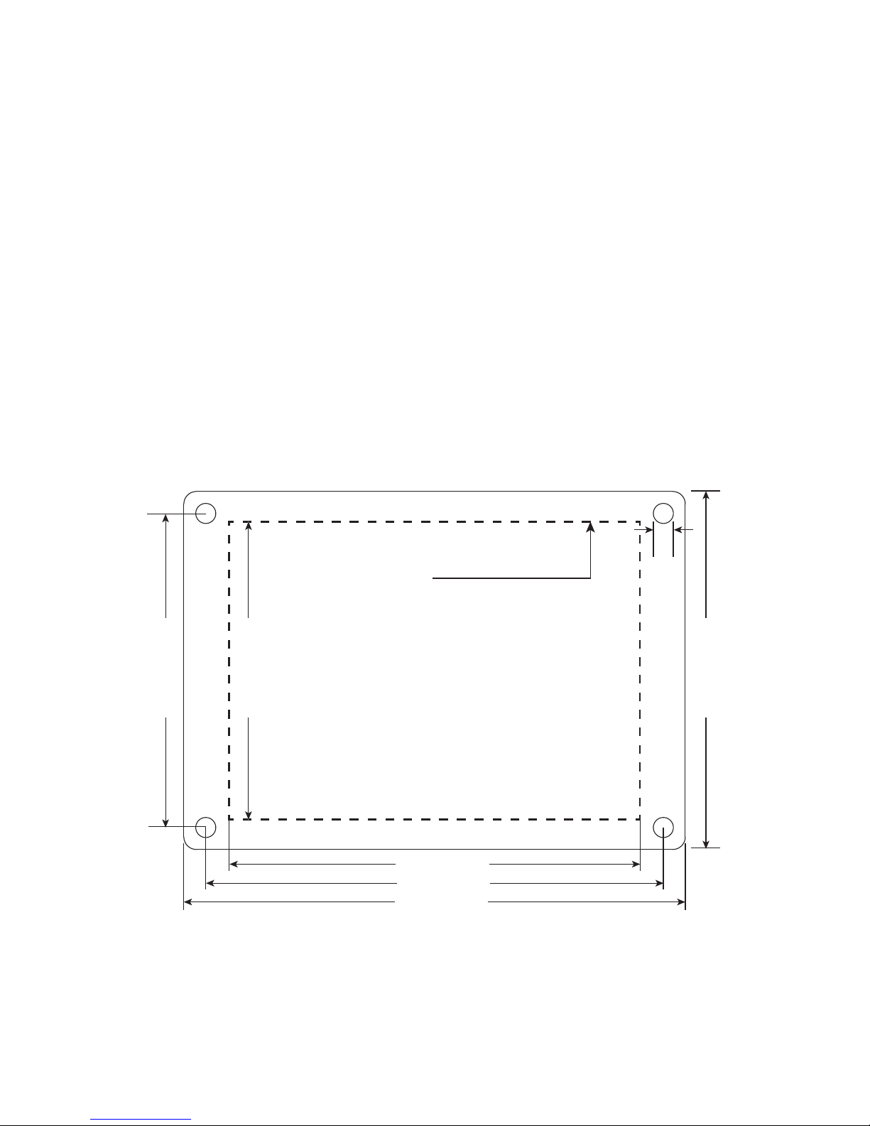
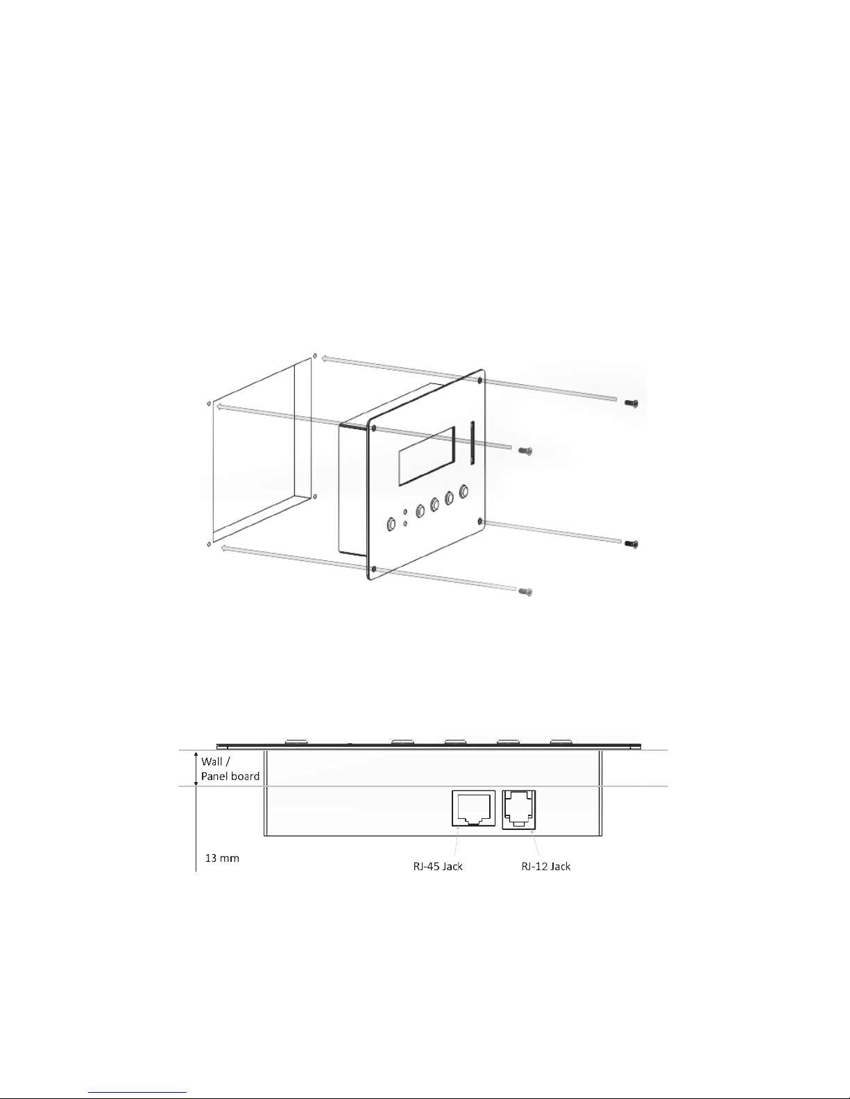
• Flush mounting of the Remote requires appropriate cut-out in the wall/panel - See Fig 2.1.
Full scale installation Template for panel cut-out and pilot holes for mounting screws is also
provided along with the unit. Take necessary precautions to ensure any wiring/plumbing running behind the wall/panel is not damaged.
• Route the wire to ensure there are no kinks.
• Use appropriate grommets when the wire is passed through holes in studs/partitions to
prevent damage to insulation.
2.1 TOOLS REQUIRED
Following tools are recommended:
• Phillips head screwdriver • Level • Hand Drill
• Knife/Saw • Pencil • Drill Bit (2mm / 5/64")
EVO-RC-PLUS Installation Template
100 mm / 3.94 in
4.2 mm / 0.17 in
114.2 mm / 4.5 in
95 mm / 3.74 in
131 mm / 5.16 in
146 mm / 5.75 in
160 mm / 6.3 in
Cut the wall / panel along the dotted
line with a jig saw.
This will create a pocket in the wall / panel
for ush mounting the EVO-RC-PLUS.
A to D: 4 pilot holes, 2mm (5/64") diameter for
accepting No. 6 x 5/7", Self Tapping,
Flat Head Screws.
A
C D
B
Fig 2.1 EVO-RC-PLUS Remote installation details
2.2 FLUSH MOUNT INSTALLATION
To ush mount, the wall opening must have at least 2” (5 cm) depth to make room for the
remote and cable. Also, the thickness of wall/panel board at the place of mounting should not be
more than 13 mm to ensure that the RJ-45 / RJ-12 Jack openings are not obstructed (see Fig. 2.3).
Page 7
SECTION 2 | Installation
1. Cut an opening in the wall using the supplied Installation Template (based on Fig 2.1).
2. Drill four pilot holes (use 2mm / 5/64" diameter drill bit) for 4 screw (Self Taping, Flat Head
No. 6 x 5/8" long) that will attach the remote to the wall (refer to Fig. 2.1 for hole locations and dimensions).
3. Route one end of the cable through wall opening to the EVOTM Inverter/Charger, and then
plug it into the RJ-45 Remote Control Jack port on the EVOTM Inverter/Charger
4. Take the other end of the remote cable and plug it into the RJ-45 / RJ-12 Jack at the back
of the EVO-RC-PLUS (Fig. 2.3).
5. Check the remote display to ensure the Power-up Self Test initiates.
6. If the self test is successful, secure the EVO-RC-PLUS to the wall using the four screws (Fig. 2.2).
Flush mounting the EVO-RC-PLUS on the wall with 4 screws:
No. 6 x 5/8", Self Tapping, Flat Head.
Fig 2.2 EVO-RC-PLUS Flush Mounting
The thickness of the wall/panel board at the place of mounting should not be
more than 13 mm to ensure that the RJ-45 / RJ-12 jack openings are not obstructed.
Fig 2.3 Wall/Panel Thickness
Page 8

8 | SAMLEX AMERICA INC.
SECTION 3 | Operation
3.0 GENERAL INFORMATION
EVO-RC-PLUS Remote Control provides the user with the ability to monitor the operation and
also to modify EVOTM Inverter/Charger’s operating parameters. The default settings in EVOTM
Inverter/Charger are adequate for some installations but may have to be modied for others.
This Section provides details on the remote functions, status and menu maps and displays, fault
messages and parameter settings.
3.1 NAVIGATING THE REMOTE
Please refer to the layout at Fig. 1.1.
• LCD Display (1) – The 4-line (20 characters each) LCD display shows status and information
for the EVOTM Inverter/Charger. All Setup Menus and faults also appear on the LCD display.
• ON/OFF Key (2) – The On/Off Key is used for switching on/ switching off the EVOTM
Inverter/Charger and also to enter/exit Standby Mode.
• Navigation Keys (5, 6, 7, 8) – These four keys allow simple access to Menu Item that
assists conguring, monitoring, and troubleshooting the EVOTM Inverter/Charger.
o Navigation Key Functions:
Back – Return to previous selection
Up – Move from lower to upper Menu Screen in various Menu Maps e.g. Fig 3.1 (a)
Down – Move from upper to lower Menu Screen in various Menu Maps
e.g. Fig 3.1(a)
Enter – Select/write a particular value or option.
• Status – Blue LED indicator for indicating operating status (see details at Section 6, Table 6.1).
• Fault – Red LED indicator for indicating fault conditions (see details at Section 6, Table 6.1).
• SD Card slot – This slot supports SD memory card (up to 16GB, FAT16/32). The SD Card
is used for data logging of EVOTM Inverter/Charger’s operational statistics and events and
saving and uploading of programmed parameters. See Section 5: SD Card.
Page 9
SECTION 3 | Operation
3.2 POWER ON / POWER OFF
i
INFO
a) Minimum battery voltage required for initiating manual switching ON of the unit
is as follows:
• 12V units ----- Higher than 9V
• 24V units ---- Higher than 18V
b) Please note that this unit is designed to POWER ON AUTOMATICALLY if (i) AC voltage of
70V ± 5 VAC is available at the AC Input Terminals and (ii) DC input voltage is > 12V for 12V
versions of EVOTM and >24V for 24V versions of EVOTM. If the AC input voltage and frequency
are within the programmed limits, the unit will automatically operate in “Charging Mode”.
If the AC input voltage and frequency are not within the programmed limits, the unit will
operate in “Inverting" Mode. Further, as long as AC input voltage > 70 ± 5 VAC is present, the
unit CANNOT BE POWERED OFF using the ON / OFF Button on the front panel of the unit or
on the Remote Control EVO-RC-PLUS. Switch OFF the AC input rst if the unit is required to
be powered off. However, if the unit is in “Fault Mode”, it will be possible to power OFF the
unit with the help of the ON/OFF Push Button.
c) Before proceeding, conrm that the unit is NOT in "Standby" Mode. If it is in "Standby
Mode", the "Status" LED (3, Fig 1.1) will ash once every 5 sec and the LED screen will
display one of the "Standby Mode" Screens show in Figs 3.1(a) / 3.1(b).
Press the On/Off Push Botton (2, Fig 1.1) on the EVO-RC-PLUS to exit the "Standby Mode"
to the current operating mode. Refer to Section 3.4 for more details on "Standby Mode".
3.2.1 Power ON - AC INPUT IS NOT PRESENT
The sequence given below is applicable when there is no AC input and the unit is switched ON.
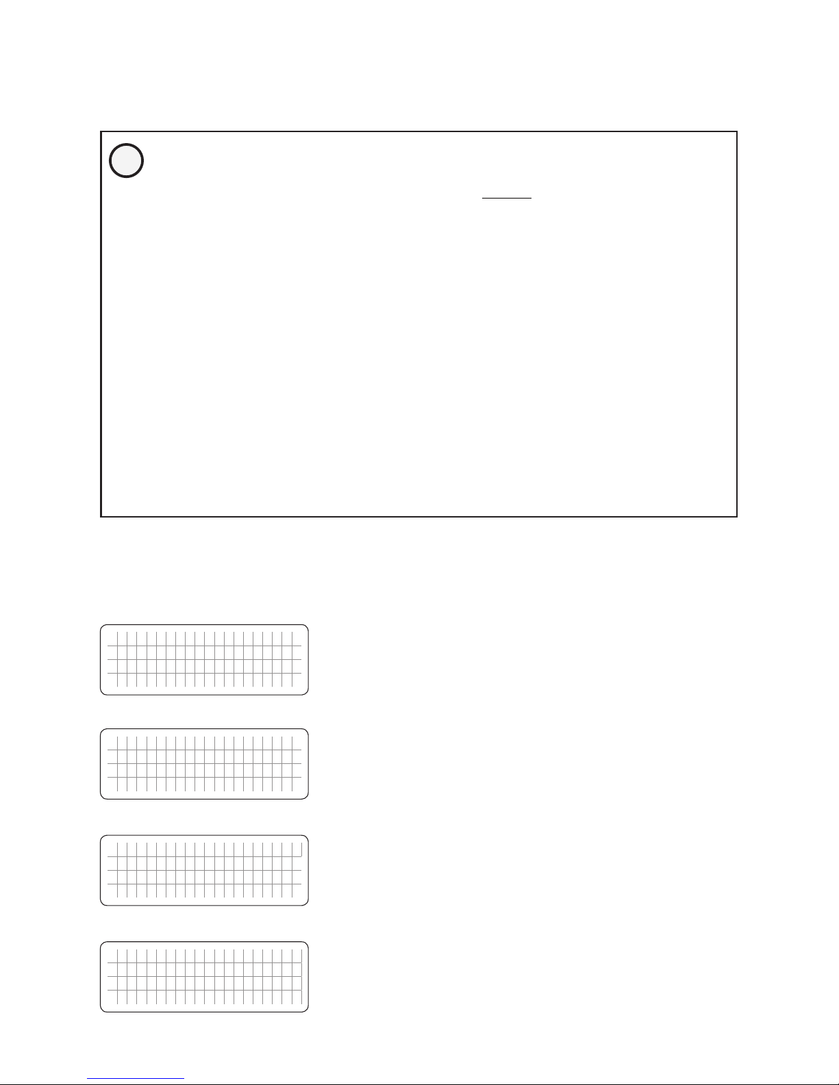
Press On/Off Key and hold for 2 second to turn the EVOTM Inverter/Charger ON.
P O W E R O N . . .
Screen (a)
S E A R C H I N G I D . . . 1
Screen (b)
E V O - 1 2 1 2 F V E R X . X X
I N V E R T E R / C H A R G E R
Screen (c)
E V O - 1 2 1 2 F I n v e r t i n g
A C o u t p u t : 1 2 0 . 0 V
< 0 . 1 A
6 0 . 0 0 H z
Screen (d)
When the EVO
TM
Inverter/Charger is OFF and the On/Off
Key is pressed and held, the LCD screen shows “POWER
ON…" [Screen (a)] and the Status LED ashes 3 times. On/
Off key may be released now. After 2 seconds, EVO-RCPLUS starts to search for the communication ID of the EVOTM
Inverter/Charger it is attached to. The LCD screen shows
“SEARCHING ID …” [Screen (b)] and the ID number which
is found is shown at the end of the line. When the default
ID of “1” is found, the display will then show the EVOTM
Inverter/Charger Model No. and rmware version (3 digit
number X.XX) [Screen (c)]. The screen will then change to
the Inverting Mode Screen [Screen (d)].
NOTE: If the EVO
TM
Inverter/Charger has AC input
voltage over 70 ± 5 VAC available at the Grid/
Generator inputs, the Power OFF function is disabled
and the unit will remain in the ON condition if the
power off sequence is attempted. The AC input must
be removed before the unit can be powered OFF.
Page 10

10 | SAMLEX AMERICA INC.
SECTION 3 | Operation
3.2.2 Power OFF - AC INPUT IS NOT PRESENT
The sequence given below is applicable when no AC input is present and the unit is powered OFF.
Press On/Off Key and hold for 5 seconds to turn OFF the EVO
TM
Inverter/Charger.
P O W E R O F F !
When EVOTM Inverter Charger is ON and the On/Off key is
pressed and held for minimum of 5 seconds, the LCD screen
will show “POWER OFF !” and both the Status and Alarm
LEDs will turn ON. Now release the On/Off key (please note
that Power Off sequence will be completed and display
“POWER OFF !” will disappear only when the On/Off
key is released).
NOTE: If the EVO
TM
Inverter/Charger has AC input
voltage over 70 ± 5 VAC available at the Grid/
Generator inputs, the Power OFF function is disabled
and the unit will remain in the ON condition if the
power off sequence is attempted. The AC input must
be removed before the unit can be powered OFF.
3.3 DATE AND TIME SETUP
Set date and time as per procedure given at Section 4.9: “Group 6 Parameter Setup: Time Setting”.
3.4 STANDBY MODE
When the EVOTM is in Standby Mode, inverting or charging / AC pass through will be suspended.
i
INFO
Standby Mode may be used to temporary halt normal operation of the Inverter/Char-
ger without switching OFF the unit completely.
For the Standby Mode to be switched ON, the EVOTM should be in ON condition and should be
operating in one of the 4 Operating Modes – “Inverting” or “Charging”, “Power Saving” or
"Online" (See Fig 3.1). When Standby Mode is switched ON, the EVOTM will exit its Operating
Mode i.e. inverting or charging / AC pass through will be suspended.
Standby Mode is toggled between ON and OFF conditions as follows:
• By momentary pressing (0.1 sec) of ON/OFF Push Key (2, Fig 1.1), OR
• By momentary pressing (0.1 sec) of ON/OFF Push Button on the front panel of the unit
(11, Fig 2.1 in the Owner’s Manual for EvolutionTM Series Inverter/Charger Models).
When the EVOTM is in “Standby Mode”, operational status will be displayed as follows:
• On the Remote Control EVO-RC-PLUS:
- Blue LED marked “Status” (3, Fig 1.1) will blink once every 5 sec. Red LED marked
“FAULT” (4, Fig 1.1) will be off
- The LCD will display "Standby" Mode screens as follows:
(i) For EVO-1212F/1212F-HW/1214F/1224F-HW: As per "Standby" Mode Menu Map
at Fig 3.2(a).
(ii) For EVO-2212/3012/2224/4024: As per "Standby" Mode Menu Map at Fig 3.2(b).
- No buzzer
Page 11

SECTION 3 | Operation
• On the front panel of EVOTM:
- No LED display. LED marked “ON” and Red LED marked “FAULT” will both be OFF.
- No buzzer
- LED marked "ON" (12, Fig 2.1 in the Owner's Manual for EvolutionTM Series
Inverter/Charger) will blink once every 5 sec.
- Red LED marked "FAULT" (13, Fig 2.1) in the Owner's Manual for EvolutionTM Series
Inverter/Charger) will be OFF.
- No buzzer
3.5. FAULT CLEARING
If any fault occurs, the LCD screen will display the Fault Message and the Red LED “Fault” will
be lighted. Remove cause of the fault. The unit will remain in Fault Mode unless it is cleared.
A short press (0.1 seconds) of the On/Off key will clear the Fault Message and the EVO
TM
Inverter/
Charger will return to the operational status (if the fault condition no longer exists). Refer to
section 7 on “Fault Messages”.
3.6 OPERATING MODES AND ASSOCIATED LCD DISPLAY SCREENS
3.6.1 General Information
When the unit is operating normally, the LCD Screen will display the name of the Operating
Mode and values of various associated operating parameters. As all the operating parameters
associated with a particular Operating Mode cannot be displayed in one screen, multiple
screens are available that can be accessed using the Up and Down Keys. For ease of navigating
through the various screens, all the screens covering a particular Operating Mode are shown and
arranged in a Menu Map – for example, see Menu Map for Inverting Mode at Figs 3.2(a) and
3.2(b). Table 3.1 shows the names of the Operating Modes and the Fig Nos. of the associated
Menu Maps.
Typical Operating Mode Display Screen is shown in Fig 3.0 [Copy of Screen 1 of Inverting Mode
Menu Map at Fig 3.2(a)]. There are 4 lines of display (up to 20 characters per line). The 1st line
shows the Model No on the left side and the Operating Mode on the right side. The 2nd, 3rd and
the 4
th
lines display various operating parameters and their values.
E V O - 1 2 1 2 F I n v e r t i n g
A C o u t p u t : 1 2 0 . 0 V
< 0 . 1
A
6 0 . 0 0 H
z
Fig 3.0 Typical Operating Mode Display Screen
[Screen No. 1 of Inverting Mode Menu Map at Fig 3.2(a)]
Page 12

12 | SAMLEX AMERICA INC.
SECTION 3 | Operation
Table 3.1 Operating Modes and Associated LCD Display Screens
Operating
Mode
Display Description
Operating Mode
Screen Menu Map
Models
EVO-1212F /
1212F HW / 1224F /
1224F-HW
Models
EVO-2212 / 3012 /
2224 / 4024
Standby Standby Mode: No output, No AC
bypass, No Charging
Fig 3.1(a),
Section 3.6.2.1
Fig 3.1 (b),
Section 3.6.2.2
Inverting Unit is operating as an inverter Fig 3.2(a),
Section 3.6.3.1
Fig 3.2(b),
Section 3.6.3.2
Charging Unit is operating as a battery charger
and passing through the AC input to
the loads
Fig 3.3(a),
Section 3.6.4.1
Fig 3.3(b),
Section 3.6.4.2
PowerSave Unit is in Power Saving Mode Fig 3.4(a),
Section 3.6.5.1
Fig 3.4(a),
Section 3.6.5.2
Online Unit is in On Line Mode Fig 3.5, Section 3.6.6
Chrg Only Under "ONLINE MODE" only (Option
2=Charger Only). Provides charging and
pass through when the AC input is available. No inverting when the AC input is
not available.
Fig 3.6(a),
Section 3.6.7.1
Fig 3.6(b),
Section 3.6.7.2
Charger Off
by BMS
Applicable when BATTERY TYPE
Option 1=Lithium is selected. This
mode is activated when the Lithium
Battery Management System (BMS)
sends command to EVO
TM
(contact
closure signal) to stop charging to
prevent battery over voltage or over
temperature.
Fig 3.7, Section 3.6.8
Inverter stop
by BMS
Applicable when BATTERY TYPE Option 1=Lithium is selected. This mode
is activated when the Lithium Battery
Management System (BMS) sends command to EVO
TM
(contact closure signal) to
stop inverting to prevent deep discharge
of the battery.
Fig 3.8, Section 3.6.9
Page 13
SECTION 3 | Operation
3.6.2 Menu Map for Standby Mode Screens
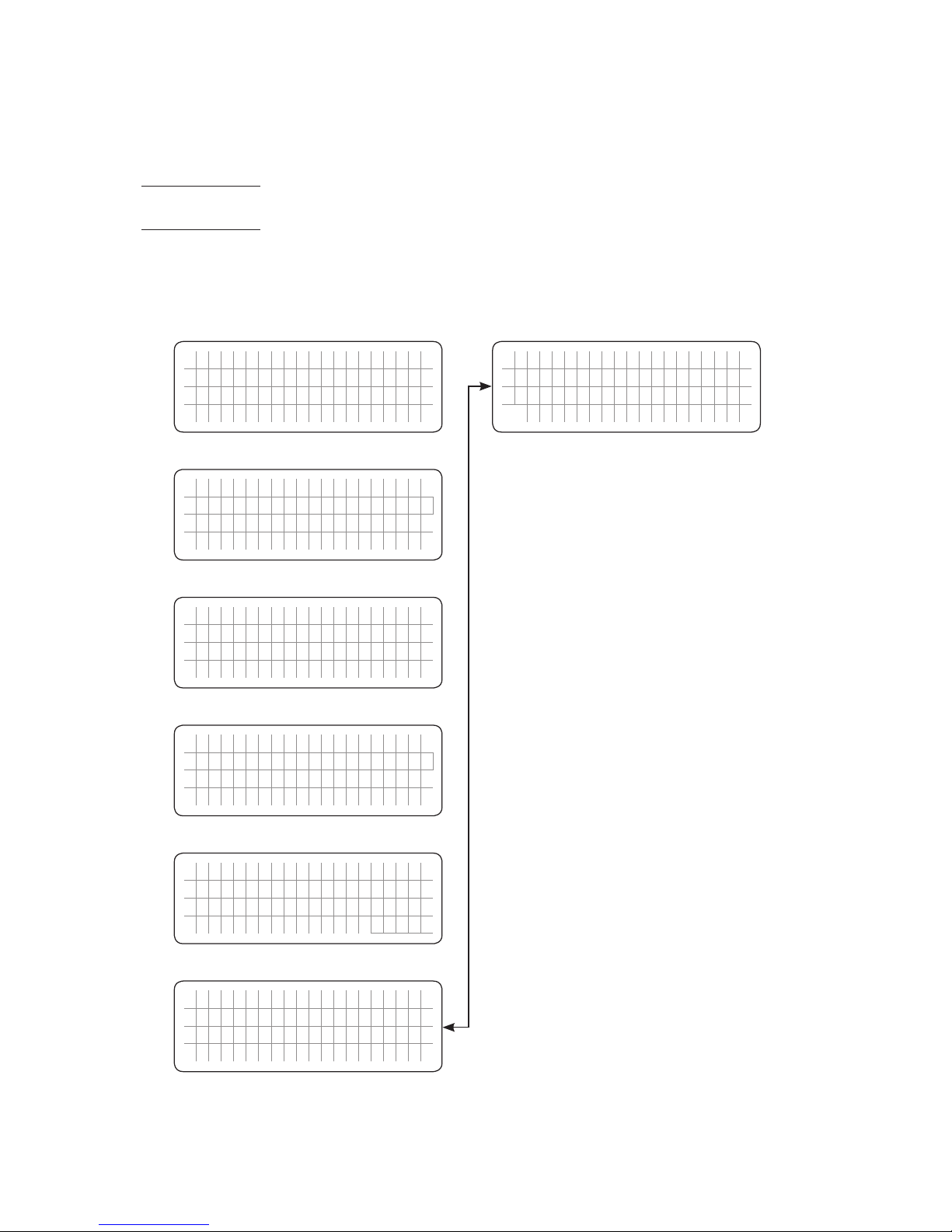
Menu Maps for the Operating Mode Screens for the Standby Mode are shown as follows:
Section 3.6.2.1: Fig 3.1(a) for Models EVO-1212F / 1212F-HW / 1224F / 1224F-HW
(Model No. shown in the screens is EVO-1212F)
Section 3.6.2.2: Fig 3.1(b) for Models EVO-2212 / 3012 / 2224 / 4024 (Model No. shown in
the screens is EVO-3012)
3.6.2.1 Menu Map for Standby Mode Screens for EVO-1212F / 1212F-HW /
1224F / 1224F-HW
NOTES:
1. The 1st line of the display screen shows
Model No. on the left and the Operating Mode
"Standby" on the right.
2. The 2
nd
, 3rd and the 4th lines show various
operating parameters and their values.
3. Use Up ñ and Down ò Keys to navigate to the
desired screen.
Up Key
Down Key
E V O - 1 2 1 2 F S t a n d b y
A C o u t p u t : 0 . 0 V
< 0 . 1 A
0 . 0 0 H z
Screen
No. 1
E V O - 1 2 1 2 F S t a n d b y
A C o u t p u t : < 1 2 W
< 1 2 V A
P F = 0 . 0 0 0
Screen
No. 2
E V O - 1 2 1 2 F S t a n d b y
A C i n p u t : 1 2 0 . 0 V
< 0 . 1 0 A
6 0 . 0 0 H z
Screen
No. 3
E V O - 1 2 1 2 F S t a n d b y
B a t t e r y : 1 2 . 0 0 V
0 . 0 A
E x t e r n a l :
0 . 0 A
Screen
No. 5
E V O - 1 2 1 2 F S t a n d b y
B a t t e r y 2 5 . 0 C
H e a t s i n k 2 5 . 0 C
T r a n s f o r m e r 2 5 . 0 C
Screen
No. 6
E V O - 1 2 1 2 F S t a n d b y
E V O V e r : x . x x I D = 1
R C V e r : x . x x
2 0 1 7 / 0 4 / 2 1 1 5 : 0 0
Screen
No. 7
ð ð ð ð
ð ð ð ð
ð
ð
E V O - 1 2 1 2 F S t a n d b y
A C i n p u t : < 1 2 W
< 1 2 V A
P F = 0 . 0 0 0
Screen
No. 4
ð
ð
Fig 3.1(a) Menu Map for Standby Mode Screens for Models EVO-1212F /
EVO-1212F-HW / 1224F / 1224F-HW (Model No. shown is EVO-1212F)
Page 14
14 | SAMLEX AMERICA INC.
SECTION 3 | Operation
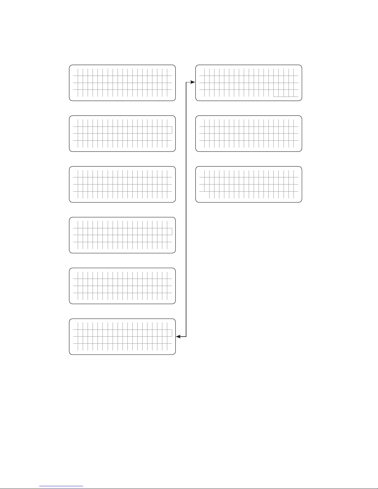
3.6.2.2 Menu Map for Standby Mode Screens for EVO-2212 / 3012 / 2224 / 4024
NOTES:
1. The 1st line of the display screen shows
Model No. on the left and the Operating Mode
"Standby" on the right.
2. The 2
nd
, 3rd and the 4th lines show various
operating parameters and their values.
3. Use Up ñ and Down ò Keys to navigate to the
desired screen.
Up Key
Down Key
E V O - 3 0 1 2 S t a n d b y
A C o u t p u t : 0 . 0 V
< 0 . 1 A
0 . 0 0 H z
Screen
No. 1
E V O - 3 0 1 2 S t a n d b y
A C o u t p u t : < 1 2 W
< 1 2 V A
P F = 0 . 0 0 0
Screen
No. 2
E V O - 3 0 1 2 S t a n d b y
G r i d : 1 2 0 . 0 V
< 0 . 1 0 A
6 0 . 0 0 H z
Screen
No. 3
E V O - 3 0 1 2 S t a n d b y
G E N : 1 2 0 . 0 V
< 0 . 1 0 A
P F = 6 0 . 0 0 H z
Screen
No. 5
E V O - 3 0 1 2 S t a n d b y
G E N : < 1 2 W
< 1 2 V A
P F = 0 . 0 0 0
Screen
No. 6
E V O - 3 0 1 2 S t a n d b y
B a t t e r y : 1 2 0 . 0 V
0 . 0 A
E x t e r n a l :
0 . 0 A
E V O - 3 0 1 2 S t a n d b y
B a t t e r y 2 5 . 0 C
H e a t s i n k 2 5 . 0 C
T r a n s f o r m e r 2 5 . 0 C
E V O - 3 0 1 2 S t a n d b y
E V O V e r : x . x x I D = 1
R C V e r : x . x x
2 0 1 7 / 0 4 / 2 1 1 5 : 0 0
Screen
No. 7
Screen
No. 8
Screen
No. 9
ð ð ð ð
ð ð ð ð
ð ð
ð ð
ð
ð
E V O - 1 2 1 2 F S t a n d b y
G r i d : < 1 2 W
< 1 2 V A
P F = 0 . 0 0 0
Screen
No. 4
ð
ð
Fig 3.1(b) Menu Map for Standby Mode Screens for
Models EVO-2212 / 3012 / 2224 / 4024
Page 15
SECTION 3 | Operation
3.6.3 Menu Map for Inverting Mode Screens
Menu Maps for the Operating Mode Screens for the "Inverting" Mode are shown as follows:
Section 3.6.3.1: Fig 3.2(a) for Models EVO-1212F / 1212F-HW / 1224F / 1224F-HW (Model
No. shown in the screens is EVO-1212F).
Section 3.6.3.2: Fig 3.2(b) for Models EVO-2212 / 3012 / 2224 / 4024 (Model No. shown
in the screens is EVO-3012).
3.6.3.1 Menu Map for Inverting Mode Screens for Models EVO-1212F /
1212F-HW / 1224F / 1224F-HW
NOTES:
1. The 1st line of the display screen shows Model
No. on the left and the Operating Mode
“Inverting” on the right
2. The 2
nd
, 3rd and the 4th lines show various
operating parameters and their values
3. Use Up ñ and Down ò Keys to navigate to the
desired screen.
Up Key
Down Key
E V O - 1 2 1 2 F I n v e r t i n g
A C O u t p u t : 1 2 0 . 0 V
< 0 . 1 0 A
6 0 . 0 0 H z
Screen
No. 1
E V O - 1 2 1 2 F I n v e r t i n g
A C O u t p u t : < 1 2 W
< 1 2 V A
P F = 0 . 0 0 0
Screen
No. 2
E V O - 1 2 1 2 F I n v e r t i n g
A C i n p u t : 1 2 0 . 0 V
< 0 . 1 0 A
6 0 . 0 0 H z
Screen
No. 3
E V O - 1 2 1 2 F I n v e r t i n g
B a t t e r y : 1 2 . 0 0 V
0 . 0 A
E x t e r n a l :
0 . 0 A
Screen
No. 5
E V O - 1 2 1 2 F I n v e r t i n g
B a t t e r y 2 5 . 0 C
H e a t s i n k 2 5 . 0 C
T r a n s f o r m e r 2 5 . 0 C
Screen
No. 6
E V O - 1 2 1 2 F I n v e r t i n g
E V O V e r : x . x x I D = 1
R C V e r : x . x x
2 0 1 7 / 0 4 / 2 1 1 5 : 0 0
Screen
No. 7
ð ð ð ð
ð ð ð ð
ð
ð
E V O - 1 2 1 2 F I n v e r t i n g
A C i n p u t : < 1 2 W
< 1 2 V A
P F = 0 . 0 0 0
Screen
No. 4
ð
ð
Fig 3.2(a) Menu Map for Inverting Mode Screens for Models EVO-1212F /
1212F-H / 1224F / 1224F-HW (Model No. Shown is EVO-1212F)
Page 16
16 | SAMLEX AMERICA INC.
SECTION 3 | Operation
3.6.3.2 Menu Map for Inverting Mode Screens for Models EVO-2212 / 3012 /
2224 / 4024
NOTES:
1. The 1st line of the display screen shows Model
No. on the left and the Operating Mode
“Inverting” on the right
2. The 2
nd
, 3rd and the 4th lines show various
operating parameters and their values
3. Use Up ñ and Down ò Keys to navigate to the
desired screen.
Up Key
Down Key
E V O - 3 0 1 2 I n v e r t i n g
O u t p u t : 1 2 0 . 0 V
< 0 . 1 0 A
6 0 . 0 0 H z
Screen
No. 1
E V O - 3 0 1 2 I n v e r t i n g
O u t p u t : < 1 2 W
< 1 2 V A
P F = 0 . 0 0 0
Screen
No. 2
E V O - 3 0 1 2 I n v e r t i n g
G r i d : 1 2 0 . 0 V
< 0 . 1 0 A
6 0 . 0 0 H z
Screen
No. 3
E V O - 3 0 1 2 I n v e r t i n g
G E N : 1 2 0 . 0 V
< 0 . 1 0 A
P F = 6 0 . 0 0 H z
Screen
No. 5
E V O - 3 0 1 2 I n v e r t i n g
< 1 2 W
< 1 2 V A
P F = 0 . 0 0 0
Screen
No. 6
E V O - 3 0 1 2 I n v e r t i n g
B a t t e r y : 1 2 . 0 0 V
0 . 0 A
E x t e r n a l : 0 . 0 A
Screen
No. 7
ð ð ð ð
ð ð ð ð
ð
ð
E V O - 3 0 1 2 I n v e r t i n g
G r i d : < 1 2 W
< 1 2 V A
P F = 0 . 0 0 0
Screen
No. 4
ð
ð
Fig 3.2(b) Menu Map for Inverting Mode Screens for Models
EVO-2212 / 3012 / 2224 / 4024 (Model No. shown is EVO-3012)
E V O - 3 0 1 2 I n v e r t i n g
B a t t e r y C
H e a t s i n k C
T r a n s f o r m e r C
E V O - 3 0 1 2 I n v e r t i n g
E V O V e r : x . x x 1 0 = 1
R C V e r : x . x x
2 0 1 7 / 0 4 / 2 1 1 5 : 0 0
ð ð
ðð
Screen
No. 8
Screen
No. 9
Page 17
SECTION 3 | Operation
3.6.4 Menu Map for Charging Mode Screens
Menu Map for the Operating Mode Screens for the "Charging" Mode are shown as follows:
Section 3.6.4.1: Fig 3.3(a) for Models EVO-1212F / 1212F-HW / 1224F / 1224F-HW
(Model No. shown in the screens is EVO-1212F).
Section 3.6.4.2: Fig 3.3(b) for Models EVO-2212 / 3012 / 2224 / 4024 (Model No. shown
in the screens is EVO-3012).
3.6.4.1 Menu Map for Charging Mode Screens for Models EVO-1212F /
1212F-HW / 1224F / 1224F-HW
Fig 3.3(a) Menu Map for Charging Mode Screens for Models EVO-1212F /
1212F-HW / 1224F / 1224F-HW (Model No. shown is EVO-1212F)
NOTES:
1. The 1st line of the display screen shows
Model No. on the left and the Operating Mode
“Charging” on the right
2. The 2
nd
line shows the Charging Stage preceded
by a numeral “0, or 1, or 2, or 3, or 4” or letter
“E” that is a code for specic type of Charging Prole (see Table 3.2). The 2nd line may also
show message “Charger off by BMS” when
parameter [Battery Type] is set for [1=Lithium].
See Section 3.6.8 and Fig 3.7 for details.
3. The 3
rd
and the 4th lines show various operating
parameters and their values
4. Use Up ñ and Down ò Keys to navigate to the
desired screen.
Up Key
Down Key
E V O - 1 2 1 2 F C h a r g i n g
0 - B u l k S t a g e
B a t t : 1 2 . 0 0 V 2 0 . 0 A
E x t e r n a l : 0 . 0 A
Screen
No. 1
E V O - 1 2 1 2 F C h a r g i n g
0 - B u l k S t a g e
A C i n : 1 2 0 . 0 V 1 0 . 0 0 A
6 0 . 0 0 H z
Screen
No. 2
E V O - 1 2 1 2 F C h a r g i n g
0 - B u l k S t a g e
A C i n : 1 2 0 0 V A 1 2 0 0 W
P F : 1 . 0 0
Screen
No. 3
E V O - 1 2 1 2 F C h a r g i n g
0 - B u l k S t a g e
A C o u t : 1 2 0 0 V A 1 2 0 0 W
P F : 1 . 0 0
Screen
No. 5
E V O - 1 2 1 2 F C h a r g i n g
B a t t e r y 2 5 . 0 C
H e a t s i n k 2 5 . 0 C
T r a n s f o r m e r 2 5 . 0 C
Screen
No. 6
E V O - 1 2 1 2 F C h a r g i n g
E V O V e r : x . x x I D = 1
R C V e r : x . x x
2 0 1 7 / 0 4 / 2 1 1 5 : 0 0
Screen
No. 7
ð ð ð ð
ð ð ð ð
ð
ð
E V O - 1 2 1 2 F C h a r g i n g
0 - B u l k S t a g e
A C o u t : 1 2 0 . 0 V 1 0 . 0 0 A
6 0 . 0 0 H z
Screen
No. 4
ð
ð
Page 18
18 | SAMLEX AMERICA INC.
SECTION 3 | Operation
3.6.4.2 Menu Map for Charging Mode Screens for Models EVO-2212 / 3012 /
2224 / 4024
Fig 3.3(b) Menu Map for Charging Mode Screens for Models
EVO-2212 / 3012 / 2224 / 4024 (Model No. shown is EVO-3012)
NOTES:
1. The 1st line of the display screen shows
Model No. on the left and the Operating Mode
“Charging” on the right
2. The 2
nd
line shows the Charging Stage preceded
by a numeral “0, or 1, or 2, or 3, or 4” or letter
“E” that is a code for specic type of Charging Prole (see Table 3.2). The 2nd line may also
show message “Charger off by BMS” when
parameter [Battery Type] is set for [1=Lithium].
See Section 3.6.8 and Fig 3.7 for details.
3. The 3
rd
and the 4th lines show various operating
parameters and their values
4. Use Up ñ and Down ò Keys to navigate to the
desired screen.
Up Key
Down Key
E V O - 3 0 1 2 C h a r g i n g
0 - B u l k S t a g e
B a t t : 1 2 . 0 0 V 2 0 . 0 A
E x t e r n a l : 0 . 0 A
Screen
No. 1
E V O - 3 0 1 2 C h a r g i n g
0 - B u l k S t a g e
A C i n : 1 2 0 . 0 V 1 0 . 0 0 A
6 0 . 0 0 H z
Screen
No. 2
E V O - 3 0 1 2 C h a r g i n g
0 - B u l k S t a g e
G r i d : 1 2 0 0 V A 1 2 0 0 W
P F : 1 . 0 0
Screen
No. 3
E V O - 3 0 1 2 C h a r g i n g
0 - B u l k S t a g e
A C o u t : 1 2 0 0 V A 1 2 0 0 W
P F : 1 . 0 0
Screen
No. 5
E V O - 3 0 1 2 C h a r g i n g
0 - B u l k S t a g e
G E N : 1 2 0 . 0 V 1 0 . 0 0 A
6 0 . 0 0 H z
Screen
No. 6
E V O - 3 0 1 2 F C h a r g i n g
0 - B u l k S t a g e
G E N : 1 2 0 0 V A 2 2 0 0 W
P F : 1 . 0 0
Screen
No. 7
ð ð ð ð
ð ð ð ð
ð
ð
E V O - 3 0 1 2 C h a r g i n g
0 - B u l k S t a g e
A C o u t : 1 2 0 . 0 V 1 0 . 0 0 A
6 0 . 0 0 H z
Screen
No. 4
ð
ð
E V O - 3 0 1 2 C h a r g i n g
B a t t e r y 2 5 . 0 C
H e a t s i n k 2 5 . 0 C
T r a n s f o r m e r 2 5 . 0 C
E V O - 3 0 1 2 C h a r g i n g
E V O V e r : x . x x 1 0 = 1
R C V e r : x . x x
2 0 1 7 / 0 4 / 2 1 1 5 : 0 0
Screen
No. 8
Screen
No. 9
Page 19

SECTION 3 | Operation
3.6.4.3 Details of Charging Proles in Charging Mode Screens
Refer to the 2nd Line of the following Charging Mode Screens:
Fig 3.3(a) under Section 3.6.4.1 for Models EVO-1212F / 1212F-HW / 1224F / 1224F-HW
Fig 3.3(b) under Section 3.6.4.2 for Models EVO-2212 / 3012 / 2224 / 4024
Details of information related to this line on the screen are shown in Table 3.2.
Table 3.2 Details of Charging Proles indicated in 2nd line of Charging Mode Screens
2
nd
Line of Screens in
Fig 3.3(a) & 3.3(b)
Description
0- Bulk Stage Constant Current, Bulk Stage, Charging Prole=0 (3-Stage Adaptive)
1- Bulk Stage Constant Current, Bulk Stage, Charging Prole=1 (3-Stage Type 1)
2- Bulk Stage Constant Current, Bulk Stage, Charging Prole=2 (3-Stage Type 2)
3- Bulk Stage Constant Current, Bulk Stage, Charging Prole=3 (2-Stage Type 1)
4- Bulk Stage Constant Current, Bulk Stage, Charging Prole=4 (2-Stage Type 2)
E- Bulk Stage Constant Current, Bulk Stage, Equalize - 4Stages (1=Yes)
0- Absorption Stage Constant Voltage, Absorption Stage, Charging Prole=0 (3-Stage Adaptive)
1- Absorption Stage Constant Voltage, Absorption Stage, Charging Prole=1 (3-Stage Type 1)
2- Absorption Stage Constant Voltage, Absorption Stage, Charging Prole=2 (3-Stage Type 2)
3- Absorption Stage Constant Voltage, Absorption Stage, Charging Prole=3 (2-Stage Type 1)
4- Absorption Stage Constant Voltage, Absorption Stage, Charging Prole=4 (2-Stage Type 2)
E- Absorption Stage Constant Voltage, Absorption Stage, Equalize - 4Stages (1=Yes)
E- Equalization Stage Constant Voltage, Equalization Stage, Equalize - 4Stages (1=Yes)
0-Float Stage Float Stage, Charging Prole=0 (3-Stage Adaptive)
1- Float Stage Float Stage, Charging Prole=1 (3-Stage Type 1)
2- Float Stage Float Stage, Charging Prole=2 (3-Stage Type 2)
3- Charger Off Charger Off, AC Bypass, Charging Prole=3 (2-Stage Type 1)
Charger Off by BMS Charger Off by BMS (Battery Type=Lithium)
Inverter Stop by BMS Inverter Stop by BMS (Battery Type: 1=Lithium)
Inverter Off Charger only, Inverter Off (Online Mode=2, Charger only)
Page 20
20 | SAMLEX AMERICA INC.
SECTION 3 | Operation
3.6.5 Menu Maps for Power Save Mode Screens
Menu Maps for the Operating Mode Screens for the Power Save Mode are shown as follows:
Section 3.6.5.1: Fig 3.4(a) for Models EVO-1212F / 1212F-HW / 1224F / 1224F-HW
(Model No. shown in the screens is EVO-1212F).
Section 3.6.5.2: Fig 3.4(b) for Models EVO-2212 / 3012 / 2224 / 4024 (Model No. shown
in the screens is EVO-3012).
3.6.5.1 Menu Maps for Power Save Mode Screens for EVO-1212F /
1212F-HW / 1224F / 1224-HW
NOTES:
1. The 1st line of the display screen shows Model
No. on the left and the Operating Mode“
PowerSave” on the right
2. The 2
nd
, 3rd and the 4th lines show various oper-
ating parameters and their values
3. Use Up ñ and Down ò Keys to navigate to the
desired screen.
Up Key
Down Key
E V O - 1 2 1 2 F P o w e r S a v e
A C o u t p u t : 0 . 0 V
< 0 . 1 0 A
6 0 . 0 0 H z
Screen
No. 1
E V O - 1 2 1 2 F P o w e r S a v e
A C o u t p u t : < 1 2 W
< 1 2 V A
P F = 0 . 0 0 0
Screen
No. 2
E V O - 1 2 1 2 F P o w e r S a v e
A C I n p u t : 1 2 0 . 0 V
< 0 . 1 0 A
6 0 . 0 0 H z
Screen
No. 3
E V O - 1 2 1 2 F P o w e r S a v e
B a t t e r y : 1 2 . 0 0 V
0 . 0 A
E x t e r n a l :
0 . 0 A
Screen
No. 5
E V O - 1 2 1 2 F P o w e r S a v e
B a t t e r y 2 5 . 0 C
H e a t s i n k 2 5 . 0 C
T r a n s f o r m e r 2 5 . 0 C
Screen
No. 6
E V O - 1 2 1 2 F P o w e r S a v e
E V O V e r : x . x x I D = 1
R C V e r : x . x x
2 0 1 7 / 0 4 / 2 1 1 5 : 0 0
Screen
No. 7
ð ð ð ð
ð ð ð ð
ð
ð
E V O - 1 2 1 2 F P o w e r S a v e
A C I n p u t : < 1 2 W
< 1 2 V A
P F = 0 . 0 0 0
Screen
No. 4
ð
ð
Fig 3.4(a) Menu Map for Power Save Mode Screens for EVO-1212F /
1212F-HW / 1224F / 1224F-HW (Model No. shown is EVO-1212F)
Page 21
3.6.5.2 Menu Maps for Power Save Mode Screens for EVO-2212 / 3012 /
2224 / 4024
NOTES:
1. The 1st line of the display screen shows Model
No. on the left and the Operating Mode“
PowerSave” on the right
2. The 2
nd
, 3rd and the 4th lines show various oper-
ating parameters and their values
3. Use Up ñ and Down ò Keys to navigate to the
desired screen.
Up Key
Down Key
E V O - 3 0 1 2 P o w e r S a v e
A C o u t p u t : 0 . 0 V
< 0 . 1 0 A
6 0 . 0 0 H z
Screen
No. 1
E V O - 3 0 1 2 P o w e r S a v e
A C o u t p u t : < 1 2 W
< 1 2 V A
P F = 0 . 0 0 0
Screen
No. 2
E V O - 3 0 1 2 P o w e r S a v e
G r i d : 1 2 0 . 0 V
< 0 . 1 0 A
6 0 . 0 0 H z
Screen
No. 3
E V O - 3 0 1 2 P o w e r S a v e
G E N : 1 2 0 . 0 V
< 0 . 1 0 A
P F = 6 0 . 0 0 H z
Screen
No. 5
E V O - 3 0 1 2 P o w e r S a v e
G E N : < 1 2 W
< 1 2 V A
P F = 0 . 0 0 0
Screen
No. 6
E V O - 3 0 1 2 P o w e r S a v e
B a t t e r y : 1 2 . 0 0 V
0 . 0 A
E x t e r n a l :
0 . 0 A
E V O - 3 0 1 2 P o w e r S a v e
B a t t e r y 2 5 . 0 C
H e a t s i n k 2 5 . 0 C
T r a n s f o r m e r 2 5 . 0 C
E V O - 3 0 1 2 P o w e r S a v e
E V O V e r : x . x x I D = 1
R C V e r : x . x x
2 0 1 7 / 0 4 / 2 1 1 5 : 0 0
Screen
No. 7
Screen
No. 8
Screen
No. 9
ð ð ð ð
ð ð ð ð
ð ð
ð ð
ð
ð
E V O - 3 0 1 2 P o w e r S a v e
G r i d : < 1 2 W
< 1 2 V A
P F = 0 . 0 0 0
Screen
No. 4
ð
ð
Fig 3.4(b) Menu Map for Power Save Mode Screens for
EVO-2212 / 3012 / 2224 / 4024 (Model No. shown is EVO-3012)
SECTION 3 | Operation
Page 22
22 | SAMLEX AMERICA INC.
SECTION 3 | Operation
3.6.6 Menu Maps for On-Line Mode Screens
Menu Maps for the On-Line Mode Screens will be similar to the following Menu Map Screens
for the default Off-Line Mode except for some changes explained below:
Mode
Menu Map Screens for Models
EVO-1212F / 1212F-HW / 1224F / 1224F-HW
Menu Map Screens for Models
EVO-2212 / 3012 / 2224 / 4024
Standby Mode Fig 3.1(a), Section 3.6.2.1 Fig 3.1(b), Section 3.6.2.2
Inverting Mode Fig 3.2(a), Section 3.6.3.1 Fig 3.2(b), Section 3.6.3.2
Charging Mode Fig 3.3(a), Section 3.6.4.1 Fig 3.3(b), Section 3.6.4.2
Power Save Mode Fig 3.4(a), Section 3.6.5.1 Fig 3.4(b), Section 3.6.5.2
In the On-Line Mode Screes, the top right of the 1st line displaying the "Operating Mode"
will switch every 2 sec between the "Operating Mode" and "Online" as shown in Fig 3.5(a)
to (d) below:
E V O - 1 2 1 2 F S t a n d b y
A C o u t p u t : 0 . 0 V
< 0 . 1 0 A
0 0 . 0 0 H z
E V O - 1 2 1 2 F I n v e r t i n g
A C o u t p u t : 1 2 0 . 0 V
< 0 . 1 0 A
6 0 . 0 0 H z
These 2 screens will switch every 2 sec These 2 screens will switch every 2 sec
E V O - 1 2 1 2 F O n l i n e
A C o u t p u t : 0 . 0 V
< 0 . 1 0 A
0 0 . 0 0 H z
E V O - 1 2 1 2 F O n l i n e
A C o u t p u t : 1 2 0 . 0 V
< 0 . 1 0 A
6 0 . 0 0 H z
Fig 3.5(a) Example of Screen No. 1
of Online / Standby Mode
Menu Map Screens
Fig 3.5(b) Example of Screen No. 1
of Online / Inverting Mode
Menu Map Screens
E V O - 1 2 1 2 F C h a r g i n g
0 - B u l k S t a g e
B a t t : 1 2 . 0 0 V 0 . 0 A
E x t e r n a l :
0 . 0 A
E V O - 1 2 1 2 F P o w e r S a v e
A C o u t p u t : 1 2 0 . 0 V
< 0 . 1 0 A
6 0 . 0 0 H z
These 2 screens will switch every 2 sec These 2 screens will switch every 2 sec
E V O - 1 2 1 2 F O n l i n e
0 - B u l k S t a g e
B a t t : 1 2 . 0 0 V 0 . 0 A
E x t e r n a l :
0 . 0 A
E V O - 1 2 1 2 F O n l i n e
A C o u t p u t : 1 2 0 . 0 V
< 0 . 1 0 A
6 0 . 0 0 H z
Fig 3.5(c) Example of Screen No. 1
of Online / Charging Mode
Menu Map Screens
Fig 3.5(d) Example of Screen No. 1
of Online / Power Save
Menu Map Screens
Page 23
SECTION 3 | Operation
3.6.7 Menu Maps for "Chgr Only" (Charger Only) Mode Screens
Menu Maps for the Operating Mode Screens for the "Chgr Only" Mode are shown as follows:
Fig 3.6(a) for Models EVO-1212F / 1212F-HW / 1224F / 1224F-HW (Model No. shown in
the screens is EVO-1212F).
Fig 3.6(b) for Models EVO-2212 / 3012 / 2224 / 4024 (Model No. shown in the screens is
EVO-3012).
3.6.7.1 Menu Map for "Chgr Only" (Charger Only) Mode Screens for
EVO-1212F / 1212F-HW / 1224F / 1224-HW
NOTES:
1.1 The 1st line of the display screen shows Model
No. on the left and “Chgr Only” Operating
Mode on the right.
1.2 When “Charger Only” Mode is selected, the
EVO
TM
will charge the batteries and pass through
the AC input power to the loads as long as AC
input is available. When the AC input fails, the
Inverter Section will NOT be activated and the
AC side loads will lose AC power. The EVOTM will
operate in Standby Mode as long as AC input
power is NOT available. LCD message on the 2nd
Line will be “Inverter Off”
2. The 2
nd
line shows message “Inverter Off” as
explained at NOTE 1.2 above
3. The 3
rd
and the 4th lines show various operating
parameters and their values
4. Use ñ and ò Keys to navigate to the desired
screen.
Up Key
Down Key
E V O - 1 2 1 2 F C h g r O n l y
I n v e r t e r O f f
B a t t : 1 2 . 0 0 V 0 . 0 A
E x t e r n a l :
0 . 0 A
Screen
No. 1
E V O - 1 2 1 2 F C h g r O n l y
I n v e r t e r O f f
A C i n : 0 . 0 V < 0 . 1 0 A
0 . 0 0 H z
Screen
No. 2
E V O - 1 2 1 2 F C h g r O n l y
I n v e r t e r O f f
A C i n : < 1 2 V A < 1 2 W
P F = 0 . 0 0 0
Screen
No. 3
E V O - 1 2 1 2 F C h g r O n l y
I n v e r t e r O f f
A C o u t : < 1 2 V A < 1 2 W
P F = 0 . 0 0 0
Screen
No. 5
E V O - 1 2 1 2 F C h g r O n l y
B a t t e r y 2 5 . 0 C
H e a t s i n k 2 5 . 0 C
T r a n s f o r m e r 2 5 . 0 C
Screen
No. 6
E V O - 1 2 1 2 F C h g r O n l y
E V O V e r : x . x x I D = 1
R C V e r : x . x x
2 0 1 7 / 0 4 / 2 1 1 5 : 0 0
Screen
No. 7
ð ð ð ð
ð ð ð ð
E V O - 1 2 1 2 F C h g r O n l y
I n v e r t e r O f f
A C o u t : 0 . 0 V < 0 . 0 0 A
0 . 0 0 H z
Screen
No. 4
ð
ð
Fig 3.6(a) Menu Map for "Charger Only" Mode Screens for Models
EVO-1212F / 1212F-HW / 1224F / 1224F-HW (Model No. shown is EVO-1212F)
ð
ð
Page 24
24 | SAMLEX AMERICA INC.
3.6.7.2 Menu Map for "Chgr Only" (Charger Only) Mode Screens for
EVO-2212 / 3012 / 2224 / 4024
NOTES:
1.1 The 1st line of the display screen shows Model
No. on the left and “Chgr Only” Operating
Mode on the right.
1.2 When “Charger Only” Mode is selected, the
EVO
TM
will charge the batteries and pass through
the AC input power to the loads as long as AC
input is available. When the AC input fails, the
Inverter Section will NOT be activated and the
AC side loads will lose AC power. The EVOTM will
operate in Standby Mode as long as AC input
power is NOT available. LCD message on the 2nd
Line will be “Inverter Off”
2. The 2
nd
line shows message “Inverter Off” as
explained at NOTE 1.2 above
3. The 3
rd
and the 4th lines show various operating
parameters and their values
4. Use ñ and ò Keys to navigate to the desired
screen.
Up Key
Down Key
E V O - 3 0 1 2 C h g r O n l y
I n v e r t e r O f f
B a t t : 1 2 . 0 0 V 0 . 0 A
E x t e r n a l :
0 . 0 A
Screen
No. 1
E V O - 3 0 1 2 C h g r O n l y
I n v e r t e r O f f
G r i d : 0 . 0 V < 0 . 1 0 A
0 . 0 0 H z
Screen
No. 2
E V O - 3 0 1 2 C h g r O n l y
I n v e r t e r O f f
G r i d : < 1 2 V A < 1 2 W
P F = 0 . 0 0 0
Screen
No. 3
E V O - 3 0 1 2 C h g r O n l y
I n v e r t e r O f f
O u t : < 1 2 V A < 1 2 W
P F = 0 . 0 0 0
Screen
No. 5
E V O - 3 0 1 2 C h g r O n l y
I n v e r t e r O f f
G E N : 0 . 0 V < 0 . 1 0 A
0 . 0 0 H z
Screen
No. 6
E V O - 3 0 1 2 C h g r O n l y
I n v e r t e r O f f
G E N : < 1 2 V A < 1 2 W
P F = 0 . 0 0 0
E V O - 3 0 1 2 C h g r O n l y
B a t t e r y 2 5 . 0 C
H e a t s i n k 2 5 . 0 C
T r a n s f o r m e r 2 5 . 0 C
E V O - 3 0 1 2 C h g r O n l y
E V O V e r : x . x x I D = 1
R C V e r : x . x x
2 0 1 7 / 0 4 / 2 1 1 5 : 0 0
Screen
No. 7
Screen
No. 8
Screen
No. 9
ð ð ð ð
ð ð ð ð
ð
ð
ð ð
E V O - 3 0 1 2 C h g r O n l y
I n v e r t e r O f f
O u t : 0 . 0 V < 0 . 0 0 A
0 . 0 0 H z
Screen
No. 4
ð
ð
Fig 3.6(b) Menu Map for "Charger Only" Mode Screens for
EVO-2212 / 3012 / 2224 / 4024 (Model No. shown is EVO-3012)
ð
ð
SECTION 3 | Operation
Page 25
SECTION 3 | Operation
3.6.8 Menu Map for "Charger Off by BMS" Mode Screens
This mode is applicable when option BATTERY TYPE 1 = Lithium is selected (see Screen No. 22 at
Table 4.3 for Group 1 Parameter Setup-CHARGE CURVE). This mode is activated when the Battery
Management System (BMS) of the Lithium Battery sends a command (contact closure) to pins 4
and 5 of the RJ-45 Temperature Sensor Jack on the EVOTM Inverter/Charger (Temperature Sensor is not required for Lithium Battery) to stop inverting to protect the Lithium Battery from deep
discharging condition. Please see details at Section 5.12.2 of Owner's Manual for EVO-1212F /
1212F-HW / 1224F / 1224F-HW.
E V O - 1 2 1 2 F C h g r O f f
E V O V e r : x . x x I D = 1
R C V e r : x . x x
2 0 1 7 / 0 4 / 2 1 1 5 : 0 0
Fig 3.7 Menu Map for "Charger Off by BMS" Mode Screens for Models
EVO-1212F / 1212F-HW / 1224F / 1224F-HW (Model No. shown is EVO-1212F)
NOTES:
1. The 1st line of the display screen will show the
following information:
• For Screens Nos. 1 to 5: Model No. on the
left and the Operating Mode “Charging”
on the right.
• For Screens Nos. 6 and 7: Model No. on
the left and the Operating Mode “Chgr
Off by BMS” on the right. This message is
shown in two parts – rst “Chgr Off” and
then “by BMS”. Each part is switched every
2 sec
2. The 2
nd
line will show the following information:
• For Screens Nos. 1 to 5: “Chgr Off by BMS”
• For Screen Nos. 6: Battery temperature :
e.g. “Battery 25.0C”
• For Screen Nos. 7: EVO Firmware Version
and Communication ID: e.g. “EVOTM Ver :
X.XX ID= 1”
3. The 3
rd
and the 4th lines show various operating
parameters and their values
4. Use Up ñ and Down ò Keys to navigate to the
desired screen.
Up Key
Down Key
E V O - 1 2 1 2 F C h a r g i n g
C h a r g e r O f f b y B M S
B a t t : 1 2 . 0 0 V 0 . 0 A
E x t e r n a l : 0 . 0 A
Screen
No. 1
E V O - 1 2 1 2 F C h a r g i n g
C h a r g e r O f f b y B M S
A C i n : 1 2 0 . 0 V 1 0 . 0 0 A
6 0 . 0 0 H z
Screen
No. 2
E V O - 1 2 1 2 F C h a r g i n g
C h a r g e r O f f b y B M S
A C i n : 1 2 0 0 V A 1 2 0 0 W
P F : 1 . 0 0
Screen
No. 3
E V O - 1 2 1 2 F C h a r g i n g
C h a r g e r O f f b y B M S
A C o u t : 1 2 0 0 V A 1 2 0 0 W
P F : 1 . 0 0
Screen
No. 5
E V O - 1 2 1 2 F C h g r O f f
B a t t e r y 2 5 . 0 C
H e a t s i n k 2 5 . 0 C
T r a n s f o r m e r 2 5 . 0 C
Screen
No. 6
Screen
No. 7
ð ð ð ð
ð ð ð ð
See
NOTE 1
ð
ð
E V O - 1 2 1 2 F C h a r g i n g
C h a r g e r O f f b y B M S
A C o u t : 1 2 0 . 0 V 1 0 . 0 0 A
6 0 . 0 0 H z
Screen
No. 4
ð
ð
"Chgr Off" for 2 sec
"by BMS" for 2 sec
"Chgr Off" for 2 sec
"by BMS" for 2 sec
See
NOTE 1
Page 26
26 | SAMLEX AMERICA INC.
SECTION 3 | Operation
3.6.9 Menu Map for "Inverter stop by BMS" Mode Screens for Models
EVO-1212F / 1212F-HW / 1224F / 1224F-HW
Menu Map for Operating Mode Screens for "Inverter stop by BMS" Mode is shown in Fig 3.8
below. This mode is applicable when option BATTERY TYPE 1 = Lithium is selected (see Screen No.
22 at Table 4.3 for Group 1 Parameter Setup-CHARGE CURVE). This mode is activated when the
Battery Management System (BMS) of Lithium Battery sends a command (contact closure) to pins
4 and 5 of the RJ-45 Temperature Sensor Jack on the EVOTM Inverter/Charger (Temperature Sensor
is not required for Lithium Battery) to stop inverting to protect the Lithium Battery from deep
discharging condition. Please see details at Section 5.12.2 of Owner's Manual for EVO-1212F /
1212F-HW / 1224F / 1224F-HW.
Fig 3.8 Menu Map for "Inverter stop by BMS" Mode Screens for Models
EVO-1212F / 1212F-HW / 1224F / 1224F-HW (Model No. shown is EVO-1212F)
"Inv stop" for 2 sec
"by BMS" for 2 sec
See NOTE 1
"Inv stop" for 2 sec
"by BMS" for 2 sec
See NOTE 1
"Inv stop" for 2 sec
"by BMS" for 2 sec
See NOTE 1
NOTES:
1. The 1st line of the display screen
shows Model No. on the left and the
Operating Mode “Inv stop by BMS”
on the right. This message is shown
in two parts – rst “Inv stop” and
then “by BMS”. Each part is switched
every 2 sec.
2. The 2
nd
, 3rd and the 4th lines show
various
operating parameters and their values
3. Use Up ñ and Down ò Keys to navigate to the desired screen.
Up Key
Down Key
E V O - 1 2 1 2 F
I n v S t o p
A C o u t p u t :
0 . 0 0 V
< 0 . 1 0 A
0 . 0 0 H z
Screen
No. 1
E V O - 1 2 1 2 F
I n v S t o p
A C o u t p u t :
< 1 2 W
< 1 2 V A
P F = 0 . 0 0 0
Screen
No. 2
E V O - 1 2 1 2 F I n v S t o p
A C i n p u t : 1 2 0 . 0 V
< 0 . 1 0 A
6 0 . 0 0 H z
Screen
No. 3
E V O - X X X X F I n v S t o p
B a t t e r y : 1 2 . 0 0 V
0 . 0 A
E x t e r n a l :
0 . 0 A
Screen
No. 5
E V O - 1 2 1 2 F I n v S t o p
B a t t e r y : 1 2 0 . 0 0 V
H e a t s i n k : 2 5 . 0 C
T r a n s f o r m e r : 2 5 . 0 C
Screen
No. 6
ð ð ð ð
ð ð ð ð
ð
ð
E V O - 1 2 1 2 F I n v S t o p
A C i n p u t : < 1 2 W
< 1 2 V A
P F = 0 . 0 0 0
Screen
No. 4
ð
ð
"Inv stop" for 2 sec
"by BMS" for 2 sec
See NOTE 1
E V O - 1 2 1 2 F I n v S t o p
E V O V e r : x . x x I D = 1
R C V e r : x . x x
2 0 1 7 / 0 4 / 2 1 1 5 : 0 0
"Inv stop" for 2 sec
"by BMS" for 2 sec
See NOTE 1
Screen
No. 7
Page 27
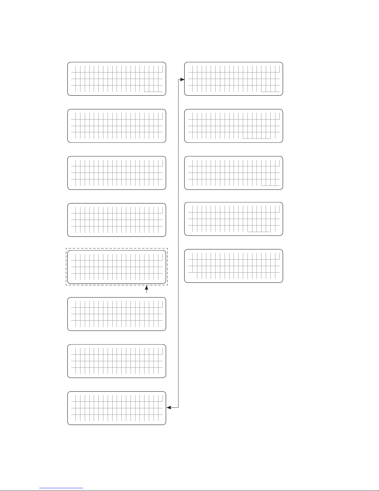
SECTION 4 | Parameter Setup
4.0 "SELECT GROUP" AND "SELECT PARAMETER" MENU MAPS
4.1.1 General Information
Up to 58 operating parameters can be programmed to suit the desired operating conditions.
The programmable parameters have been arranged under 7 Parameter Groups as per details at
Table 4.1 below. "Select Group" Menu Map for accessing the 7 Parameter Groups is shown at
Fig 4.1.
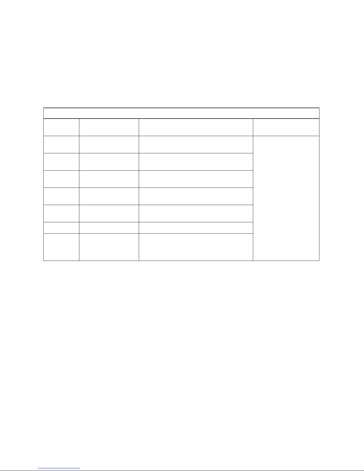
Table 4.1 List of Parameter Group Nos. 1 to 7
Parameter
Group No.
Parameter
Group Name Description
"Select Group"
Menu Map
1 CHARGE CURVE Parameters for battery charging/battery
protection
Fig 4.1
2 INPUT SETTING Parameters for Grid/Generator input
current level, frequency range
3 INPUT LOW LIMIT Parameters for Grid/Generator input low
voltage level
4 INPUT HIGH LIMIT Parameters for Grid/Generator input high
voltage level
5 OTHER FUNCTION Power Saving/Buzzer/Remote Switch/
Multi-function Relay/etc.
6 TIME SETTING Real Time Clock setting
7 STOP SD CARD Shown only when SD Card is inserted.
To stop SD Card accessed and to remove
the SD Card.
The 1st screen for Group 1 - CHARGE CURVE will be accessed when Enter key is pressed
momentarily from any of the Operating Mode Display Screens detailed at Table 3.1.
Fig 4.1 shows "Select Group" Menu Map for 7 Parameter Groups. Use the Up and Down
keys to navigate to the desired Parameter Group or the Back key to go back to the Operating
Mode Screen. Press Enter to access Parameters in the selected Parameter Group.
For explanation of the format of the "Select Group Screens" shown in Fig 4.1, consider
Group 1 Screen - CHARGE CURVE. The 1st line shows the action i.e. "Select Group". The 2
nd
line shows the name of the "Select Group" - CHARGE CURVE with an asterisk sign * against
it. The asterisk sign * indicates that this Group will be selected when Enter key is pressed.
Page 28
28 | SAMLEX AMERICA INC.
4.1.2 "Select Group" Menu Map
Menu Map for "Select Group" is shown at Fig 4.1 below:
S e l e c t G r o u p
* C H A R G E C U R V E
Screen No. 1
for Group 1
S e l e c t G r o u p
* I N P U T S E T T I N G
S e l e c t G r o u p
* I N P U T L O W L I M I T
S e l e c t G r o u p
* O T H E R F U N C T I O N
S e l e c t G r o u p
* T I M E S E T T I N G
ð ð ð ð
ð ð ð ð
NOTES:
1. Asterisk sign * in the beginning of the 2nd
line of the display screen points that the
parameter shown in this line will be selected
for further programming when the Enter Key
is pressed
2. Screen No. 7 for Group 7 will be displayed only
when the SD Card is inserted
3. Use Up ñ and Down ò Keys to navigate to
the desired screen.
Up Key
Down Key
ð
ð
S e l e c t G r o u p
* I N P U T H I G H L I M I T
ð
ð
Screen No. 2
for Group 2
Screen No. 3
for Group 3
Screen No. 4
for Group 4
Screen No. 5
for Group 5
Screen No. 6
for Group 6
S e l e c t G r o u p
* S T O P S D C A R D
ð
ð
Screen No. 7
for Group 7
See NOTE 2
Fig 4.1 "Select Group" Menu Map
SECTION 4 | Parameter Setup
Page 29
4.1.3 "Select Parameter" Menu Map
When any of the 7 Parameter Groups from the "Select Group" Menu Map (Fig 4.1) is selected,
access is available to the "Select Parameter" Menu Map pertaining to that Group. Location of
"Select Parameter" Menu Maps are given in Table 4.2.
Table 4.2 Locations of "Select Parameter" Menu Maps
"Select Group"
Menu Map (Fig 4.1)
Column (1)
Location of "Select
Parameter" Menu Map
Column (2)
Location of TABLES
for Parameter details
Column (3)
Group 1 - CHARGE CURVE Fig 4.2
Table 4.3 (Section 4.4)
Group 2 - INPUT SETTING Fig 4.3
Table 4.4 (Section 4.5)
Group 3 - INPUT LOW LIMIT Fig 4.3
Table 4.5 (Section 4.6)
Group 4 - INPUT HIGH LIMIT Fig 4.3
Table 4.6 (Section 4.7)
Group 5 - OTHER FUNCTION Fig 4.4
Table 4.7 (Section 4.8)
Group 6 - TIME SETTING Fig 4.5
Section 4.9
Group 7 - STOP SD CARD Fig 4.5
Section 4.10
NOTE: Figs 4.2 to 4.4 show the default/factory preset parameters for EVO-1212F / 1212F-HW.
For parameters for other Models, refer to Tables shown under Column (3) of Table 4.2.
For explanation of the format of the "Select Parameter" screen, refer to Fig 4.2, Screen
No. 1 - "Select Parameter" - BULK CURRENT (extract given below):
S e l e c t P a r a m e t e r
C H A R G E C U R V E
* B U L K C U R R E N T
2 0 A
Screen
No. 1
NOTE: The information in
this screen pertains to
Model No. EVO-1212F
• The 2nd line shows the Parameter Group - CHARGE CURVE in this case
• The 3rd line - "BULK CURRENT" in this case shows that this parameter is earmarked
for programming. The asterisk * against this line shows that this parameter will be
accessed for programming when Enter key is pressed.
• The 4th line shows the default/factory preset value for BULK CURRENT (20A for
EVO-1212F / 1212F-HW).
• Refer to Tables shown in Column 3 of TABLE 4.2 above for parameter details for
various models.
SECTION 4 | Parameter Setup
Page 30
30 | SAMLEX AMERICA INC.
SECTION 4 | Parameter Setup
4.1.3.1 "Select Parameter" Menu Map for Parameter Group 1: CHARGE CURVE
S e l e c t P a r a m e t e r
C H A R G E C U R V E
* B U L K C U R R E N T
2 0 A
Screen
No. 1
S e l e c t P a r a m e t e r
C H A R G E C U R V E
* A B S O R P V O L T A G E
1 4 . 4 0 V
Screen
No. 2
S e l e c t P a r a m e t e r
C H A R G E C U R V E
* E Q U A L I Z E V O L T A G E
1 4 . 4 0 V
Screen
No. 3
S e l e c t P a r a m e t e r
C H A R G E C U R V E
* C O M P E N S A T E
4 m V /°C / C e l l
Screen
No. 5
S e l e c t P a r a m e t e r
C H A R G E C U R V E
* B A T T O V E R V O L T
1 6 . 0 0 V
Screen
No. 6
ð ð ð ð
ð ð ð ð
S e l e c t P a r a m e t e r
C H A R G E C U R V E
* F L O A T V O L T A G E
1 3 . 5 0 V
Screen
No. 4
ð
ð
S e l e c t P a r a m e t e r
C H A R G E C U R V E
* R E S E T V O L T A G E
1 4 . 0 0 V
Screen
No. 7
S e l e c t P a r a m e t e r
C H A R G E C U R V E
* L O W V O L T A L A R M
1 1 . 0 0 V
Screen
No. 8
ð ð
ð ð
S e l e c t P a r a m e t e r
C H A R G E C U R V E
* B A T T L O W V O L T A G E
1 0 . 5 0 V
Screen
No. 9
S e l e c t P a r a m e t e r
C H A R G E C U R V E
* L V D E T E C T T I M E
1 0 s e c
Screen
No. 10
S e l e c t P a r a m e t e r
C H A R G E C U R V E
* L V C U T O F F T I M E
1 2 0 0 s e c
Screen
No. 11
S e l e c t P a r a m e t e r
C H A R G E C U R V E
* M O D E
0 = N o r m a l
Screen
No. 13
S e l e c t P a r a m e t e r
C H A R G E C U R V E
* O N L I N E O P T I O N
0 = O p t i o n 1
Screen
No. 14
ð ð ð ð
ð ð ð ð
S e l e c t P a r a m e t e r
C H A R G E C U R V E
* E Q U A L I Z E - 4 S T A G E S
0 = N o
Screen
No. 12
ð
ð
S e l e c t P a r a m e t e r
C H A R G E C U R V E
* R E S E T T O B U L K
1 2 . 0 0 V
Screen
No. 15
S e l e c t P a r a m e t e r
C H A R G E C U R V E
* G S D E T E C T T I M E
1 0 s e c
Screen
No. 16
ð ð
ð ð
S e l e c t P a r a m e t e r
C H A R G E C U R V E
* G E N O N T I M E
6 0 m i n
Screen
No. 17
S e l e c t P a r a m e t e r
C H A R G E C U R V E
* G E N O F F D E L A Y
6 0 m i n
Screen
No. 18
S e l e c t P a r a m e t e r
C H A R G E C U R V E
* A B S O R P T I M E
6 0 m i n
Screen
No. 19
S e l e c t P a r a m e t e r
C H A R G E C U R V E
* C H A R G I N G P R O F I L E
0 = 3 S t a g e A d a p t i v e
Screen
No. 21
S e l e c t P a r a m e t e r
C H A R G E C U R V E
* B A T T E R Y T Y P E
0 = L e a d A c i d
Screen
No. 22
ð ð ð ð
ð ð ð ð
S e l e c t P a r a m e t e r
C H A R G E C U R V E
* A B S O R P E X I T A M P S
4 A
Screen
No. 20
ð
ð
NOTES:
1. Value shown in the 4
th
line of the display screen is the default / factory pre-set values (EVO-1212F / 1212F-HW
in this case). Refer to Table 4.3 (Section 4.4.1) for the default / factory pre-set values and additional program
-
ming details for the other Models
2. Asterisk sign * in the beginning of the 3
rd
line of the display screen points that the parameter shown in this
line will be selected for further programming when the Enter Key is pressed
3. Use Up ñ and Down ò Keys to navigate to the desired screen.
Up Key
Down Key
ð
ð
Fig 4.2 "Select Parameter" Menu Map for Parameter Group 1 - CHARGE CURVE
Page 31
4.1.3.2 "Select Parameter" Menu Maps for (i) Parameter Group 2: INPUT
SETTING, (ii) Parameter Group 3: INPUT LOW LIMIT and (iii) Parameter
Group 4: INPUT HIGH LIMIT.
S e l e c t P a r a m e t e r
I N P U T S E T T I N G
* D E F A U L T F R E Q
0 = 6 0 H z
Screen
No. 1
S e l e c t P a r a m e t e r
I N P U T S E T T I N G
* G R I D M A X C U R R E N T
2 0 . 0 0 A
Screen
No. 2
S e l e c t P a r a m e t e r
I N P U T S E T T I N G
* G E N M A X C U R R E N T
3 0 . 0 0 A
Screen
No. 3
S e l e c t P a r a m e t e r
I N P U T S E T T I N G
* H I G H R E S E T
6 4 . 0 0 H z
Screen
No. 5
S e l e c t P a r a m e t e r
I N P U T S E T T I N G
* L O W C U T O F F
5 5 . 0 0 H z
Screen
No. 6
ð ð ð ð
ð ð ð ð
S e l e c t P a r a m e t e r
I N P U T S E T T I N G
* H I G H C U T O F F
6 5 . 0 0 H z
Screen
No. 4
ð
ð
S e l e c t P a r a m e t e r
I N P U T S E T T I N G
* L O W R E S E T
5 6 . 0 0 H z
Screen
No. 7
ð
ð
S e l e c t P a r a m e t e r
I N P U T L O W L I M I T
* R E S E T V O L T A G E
1 0 5 . 0 V
S e l e c t P a r a m e t e r
I N P U T L O W L I M I T
* C U T O F F V O L T 1
1 0 0 . 0 V
S e l e c t P a r a m e t e r
I N P U T L O W L I M I T
* D E T E C T T I M E 1
3 0 0 c y c l e
S e l e c t P a r a m e t e r
I N P U T L O W L I M I T
* D E T E C T T I M E 2
6 0 c y c l e
S e l e c t P a r a m e t e r
I N P U T L O W L I M I T
* C U T O F F V O L T 3
9 0 . 0 V
ð ð ð ð
ð ð ð ð
S e l e c t P a r a m e t e r
I N P U T L O W L I M I T
* C U T O F F V O L T 2
9 5 . 0 V
ð
ð
S e l e c t P a r a m e t e r
I N P U T L O W L I M I T
* D E T E C T T I M E 3
1 c y c l e
ð
ð
NOTES:
1. Value shown in the 4
th
line of the display screen is the default / factory pre-set values (EVO-1212F / 1212F-HW
in this case). For the default / factory pre-set values and additional programming details for the other Models,
refer to
(i) Table 4.5 (Section 4.5) for “INPUT SETTING”, (ii) Table 4.6 (Section 4.6) for “INPUT LOW LIMIT” and
(iii) Table 4.7 (Section 4.7) for “INPUT HIGH LIMIT”.
2. Asterisk sign * in the beginning of the 3rd line of the display screen points that the parameter shown in this
line will be selected for further programming when the Enter Key is pressed
3. Screen No. 3 is displayed only in Model Nos. that have Generator input terminals (EVO-2212 / 3012 / 2224 /
4024). These screens are NOT displayed in EVO-1212F / 1212F-HW and EVO-1224F / 1224F-HW
4. Use Up ñ and Down ò Keys to navigate to the desired screen.
Up Key
Down Key
ð
ð
S e l e c t P a r a m e t e r
I N P U T H I G H L I M I T
* R E S E T V O L T A G E
1 2 5 . 0 V
S e l e c t P a r a m e t e r
I N P U T H I G H L I M I T
* C U T O F F V O L T 1
1 3 5 . 0 V
S e l e c t P a r a m e t e r
I N P U T H I G H L I M I T
* D E T E C T T I M E 1
6 0 c y c l e
S e l e c t P a r a m e t e r
I N P U T H I G H L I M I T
* D E T E C T T I M E 2
1 5 c y c l e
S e l e c t P a r a m e t e r
I N P U T H I G H L I M I T
* C U T O F F V O L T 3
1 4 5 . 0 V
ð ð ð ð
ð ð ð ð
S e l e c t P a r a m e t e r
I N P U T H I G H L I M I T
* C U T O F F V O L T 2
1 4 0 . 0 V
ð
ð
S e l e c t P a r a m e t e r
I N P U T H I G H L I M I T
* D E T E C T T I M E 3
1 c y c l e
ð
ð
Screen
No. 1
Screen
No. 2
Screen
No. 3
Screen
No. 5
Screen
No. 6
Screen
No. 4
Screen
No. 7
Screen
No. 1
Screen
No. 2
Screen
No. 3
Screen
No. 5
Screen
No. 6
Screen
No. 4
Screen
No. 7
Parameter Group 2
"INPUT SETTING"
Parameter Group 3
"INPUT LOW LIMIT"
Parameter Group 4
"INPUT HIGH LIMIT"
Fig 4.3 "Select Parameter" Menu Maps for (i) Parameter Group 2:
INPUT SETTING, (ii) Parameter Group 3: INPUT LOW LIMIT and
(iii) Parameter Group 4: INPUT HIGH LIMIT.
SECTION 4 | Parameter Setup
See NOTE 3
Page 32
32 | SAMLEX AMERICA INC.
4.1.3.3 "Select Parameter" Menu Map for Parameter Group 5: OTHER FUNCTION
NOTES:
1. Value shown in the 4th line of the display screen
is the default / factory pre-set values (EVO-1212F
/ 1212F-HW in this case). For the default / factory
pre-set values and additional programming details
for the other Models, refer to Table 4.8 (Section 4.8)
for “OTHER FUNCTION”
2. Asterisk sign * in the beginning of the 3
rd
line of the
display screen points that the parameter shown in
this line will be selected for further programming
when the Enter Key is pressed
3. Screen No. 5 is displayed only in Model Nos. that have
Generator input terminals. These screens are NOT
displayed in EVO-1212F / 1212F-HW and EVO-1224F
/ 1224F-HW
4. Use ñ and ò Keys to navigate to the desired screen.
Up Key
Down Key
ð
ð
S e l e c t P a r a m e t e r
O T H E R F U N C T I O N
* P O W E R S A V I N G
0 = D i s a b l e
Screen
No. 1
S e l e c t P a r a m e t e r
O T H E R F U N C T I O N
* E N T E R P O I N T
6 W
Screen
No. 2
S e l e c t P a r a m e t e r
O T H E R F U N C T I O N
* W A K E U P P O I N T
7 W
Screen
No. 3
S e l e c t P a r a m e t e r
O T H E R F U N C T I O N
* R E L A Y F U N C T I O N
2 = G e n e r a t o r 0
Screen
No. 5
S e l e c t P a r a m e t e r
O T H E R F U N C T I O N
* C O M M . I D
1
Screen
No. 6
S e l e c t P a r a m e t e r
O T H E R F U N C T I O N
* D E F A U L T R E S E T
0 = N o
S e l e c t P a r a m e t e r
O T H E R F U N C T I O N
* D I A L O G T I M E
1 = 1 s e
c
S e l e c t P a r a m e t e r
O T H E R F U N C T I O N
* P A R A M E T E R S A V E
0 = N o
Screen
No. 9
Screen
No. 10
Screen
No. 11
ð ð ð ð
ð ð ð ð
ð
ð
ð ð
S e l e c t P a r a m e t e r
O T H E R F U N C T I O N
* R E M O T E S W I T C H
0 = B u t t o n
Screen
No. 4
ð
ð
S e l e c t P a r a m e t e r
O T H E R F U N C T I O N
* B U Z Z E R
1 = O n
Screen
No. 7
S e l e c t P a r a m e t e r
O T H E R F U N C T I O N
* D I S C H A R G E B E E P
1 = O f f
Screen
No. 8
ð ð
ð ð
S e l e c t P a r a m e t e r
O T H E R F U N C T I O N
* T E M P U N I T
0 = C
S e l e c t P a r a m e t e r
O T H E R F U N C T I O N
* P A S S W O R D D I S A B L E
0 = D i s a b l e
Screen
No. 12
Screen
No. 13
ð
ð
ð ð
See NOTE 3
Fig 4.4 "Select Parameter" Menu Map for Parameter Group 5: OTHER FUNCTION
SECTION 4 | Parameter Setup
Page 33

4.1.3.4 "Select Parameter" Menu Maps for (i) Parameter Group 6: TIME SETTING and (ii) Parameter Group 7: STOP SD CARD
S e l e c t P a r a m e t e r
T I M E S E T T I N G
* E n t e r t h e t i m e
2 0 0 0 / 0 1 / 0 1 0 0 : 0 0
S e l e c t P a r a m e t e r
S T O P S D C A R D
0 = N o
NOTE:
Value shown in the 4th line of the display screen is the default / factory pre-set value. For additional programming
details, refer to (i) Section 4.9 for “TIME SETTING” and (ii) Section 4.10 for STOP SD CARD”
Group 6
"TIME SETTING"
Group 7
"STOP SD CARD"
Fig 4.5 "Select Parameter" Menu Map for (i) Parameter Group 6:
TIME SETTING and (ii) Parameter Group 7: STOP SD CARD.
4.2 PARAMETER SETUP PROCEDURE
4.2.1 General Information - Parameter Setup Procedure
Please refer to Fig 4.6.
The Enter key is used to enter "Select Group" Menu Map from any Operating Mode Screen shown
in Figs 3.1 to 3.5.
Example in Fig 4.6 starts with Inverting Mode Screen [(Screen 1 in Figs 3.2(a) and 3.2(b)]. After
the Enter key is pressed, the Up/Down keys are used to navigate to one of the 7 "Select Group"
Screens (Fig 4.1). When the Group for the desired setting is displayed on the LCD, the Enter Key
is used again to select this Group. The Up and Down Keys are used to move to the individual
screens within the Group.
Pressing the Back Key will exit to the previous level.
i
INFO
There is a 30 second timeout for setting parameters; after 30 seconds the Setting
Mode will be cancelled and the display will revert to the Operating Mode Screen
associated with current operation.
It is highly recommended to set the EVOTM Date and Time (Parameter Group 6, Screen No. 6 in
Fig 4.1)) as this value is used to record data logging les. (Refer to Section 4.9 for Date
and Time set up).
SECTION 4 | Parameter Setup
Page 34

34 | SAMLEX AMERICA INC.
E V O - 1 2 1 2 F I n v e r t i n g
A C o u t p u t : 1 2 0 . 0 V
< 0 . 1 0 A
6 0 . 0 0 H z
S e l e c t G r o u p
* C H A R G E C U R V E
Screen
No. 1 for
Group 1
S e l e c t G r o u p
* I N P U T S E T T I N G
S e l e c t G r o u p
* I N P U T L O W L I M I T
S e l e c t G r o u p
* O T H E R F U N C T I O N
S e l e c t G r o u p
* T I M E S E T T I N G
ð ð ð ð
ð ð ð ð
S e l e c t G r o u p
* I N P U T H I G H L I M I T
ð
ð
S e l e c t G r o u p
* S T O P S D C A R D
ð
ð
S e l e c t P a r a m e t e r
C H A R G E C U R V E
* B U L K C U R R E N T
2 0 A
Any Operating Mode
Screen from Fig 3.1 to 3.5
"Select Group"
Menu Map (Fig 4.1)
"Select Parameter" Screen
(Figs 4.2 to 4.5)
(eg. BULK CURRENT:
Screen No. 1, Fig 4.2)
Press Down Key
Press Up Key
Press Enter Key
Press Back Key
ð
ð
ð
ð
Screen
No. 2 for
Group 2
Screen
No. 3 for
Group 3
Screen
No. 4 for
Group 4
Screen
No. 5 for
Group 5
Screen
No. 6 for
Group 6
Screen
No. 7 for
Group 7
ð
ð
ð
ð
NOTE:
Will be displayed only
when SD Card is inserted.
Fig 4.6 Example - Navigating from Operating Mode Screen to
"Select Parameter" Screen for Parameter "BULK CURRENT"
4.2.2 Changing / Entering Parameter Values
Each parameter has a programmable range of values specic to the model number of the
EVOTM. Please refer to Tables 4.3 and 4.5 to 4.8 and Sections 4.9 and 4.10 for details. During
parameter programming, the displayed numerical value of the parameter consists of multiple digits that are necessary to display the highest numerical value within the programmable
range. For example, the programmable range for the parameter BULK CURRENT for EVO1212F / 1212F-HW is 0-60A (Table 4.3). The highest numerical value is “60” and consists of
SECTION 4 | Parameter Setup
[Above screen is Screen 1 of Fig 3.2(a)]
Page 35

2 digits. Hence, for EVO-1212F / 1212F-HW, the numerical value of BULK CURRENT will be
displayed /entered as 2 digits. For example, 1A will be displayed / entered as “1A”; 20A will
be displayed / entered as "20A" and so on. The overall numerical value of the parameter is
changed digit by digit starting from the 1st digit on the left. On entering the desired "Select
Parameter" Screen (Figs 4.2 to 4.5), a curser will appear under the 1st digit and the cursor
and the digit will be blinking. Scroll to the desired numerical value for the 1st digit using Up
and Down Keys. Press the Enter Key momentarily to write the desired numerical value for
the 1st digit. The curser will automatically move to the 2nd digit on the right. The 2nd digit and
the curser and the digit will be blinking. Scroll to the desired numerical value for the 2nd digit
with the help of Up and Down Keys. Then, press the Enter Key momentarily to write the
desired numerical value for the 2nd digit. The overall numerical value of the parameter will be
selected after scrolling to the desired numerical value for the last digit. Now, press the Enter
Key, HOLD for 3 to 4 sec and then release. Process for writing the overall numerical value
of the parameter into the memory will be initiated – the screen will display message “Writing…” followed by message “Write Success!”.
Please read Section 4.3.1 for example of programming a typical parameter – BULK CURRENT
i
INFO
1. When the numerical value for any individual digit is changed that makes the
overall numerical value of the parameter outside the programmable range, an
Exclamation Sign “!” will appear on the left of the display screen warning you
to correct the overall numerical value of the parameter to within the programmable range before writing the new overall numerical value of the parameter to
memory. See Tables 4.3 and 4.5 to 4.8 and Sections 4.9 and 4.10 for programmable ranges.
2. If, after scrolling to the desired numerical value for the last digit, the overall numerical value of the parameter is out of the programmable range, the Exclamation
Sign “!” will continue to appear on the left of the display screen. If an attempt
is made to write this “out of range overall numerical value” into the memory (by
pressing and holding the Enter Key when the cursor is at the last digit), message
“Out of range!” will be displayed and the screen will go back to display the originally stored value of the parameter. Parameter set up procedure will have to
be re-started.
3. If there is some problem in writing to the memory, message “Write failure!” will
be displayed. Parameter set up procedure will have to be re-started.
4.3 PASSWORD PROTECTION FOR PARAMETER CHANGE
In the factory preset (Default) condition, all parameters except Time and Date are protected
with a Password. This has been done to prevent accidental / unintentional changes of
parameter values. When the required "Select Parameter" Screen is reached and is displayed and
Enter Key is pressed to modify the parameter value, the system will request a 4-digit Password.
The Password is 8052. Once you Enter the Password correctly, you don’t need to enter the
Password again until any Key is not pressed for over 60 seconds. An example of Parameter
setting is shown at Section 4.3.1. NOTE: Password protection may be disabled, if required
– See Section 4.3.2.
SECTION 4 | Parameter Setup
Page 36

36 | SAMLEX AMERICA INC.
SECTION 4 | Parameter Setup
4.3.1 Example of Password Activation and Changing Bulk Current Setting for
EVO-1212F / 1212F-HW from Default Value of 20A to 50A
S e l e c t G r o u p
* C H A R G E C U R V E
Starting from any of the 5 Operating Mode Screens (shown
at Figs 3.1 to 3.8), press Enter Key. Screen "Select Group,
CHARGE CURVE" as shown on the left will be displayed
(Parameter Group 1 of "Select Group" Menu Map, Fig 4.1)
Press Enter key to access 22 Parameter Screens under
"Select Parameter" Menu Map for Parameter Group 1
"Charge Curve" (Fig 4.2) [Parameters are detailed at Table
4.3 under Section 4.4.1].
S e l e c t G r o u p
* C H A R G E C U R V E
B U L K C U R R E N T
2 0 A
Screen "BULK CURRENT, 20A" as shown on the left will be
displayed (Screen No.1 of "Select Parameter" Menu Map
for Parameter Group 1: CHARGE CURVE at Fig 4.2). Default
current setting of 20A or previously set value will be displayed.
Press Enter Key to change Bulk Current parameter setting.
A Password will be requested. Password will not be
requested if disabled - see Section 4.3.2).
P a s w o r d k e y i n
0 0 0 0
Password consisting of 4 digits "0000" will be requested as
shown on the left. The rst digit will have a blinking cursor
" ". Use Up /Down Keys to scroll to number 8 for the rst
digit “8” of the password. Momentarily press Enter Key
(Short press). Digit 8 will be entered as the rst digit of the
Password and the blinking cursor will automatically move to
the 2nd digit (0) to the right. As the next digit in the Password
“8052” is already “0”, momentarily press Enter Key (Short
press) to enter “0” in the second digit. The blinking cursor will
automatically move to the 3rd digit (0). Use Up /Down Keys
to scroll to number 5 for the 3rd digit “5” of the password
“8052” and momentarily press Enter Key (Short press).
The blinking cursor will automatically move to the 4th digit
(0). Use Up /Down Keys to scroll to number 2 for the 4th
digit “2” of the password “8052”. Now keep the Enter Key
pressed continuously for longer time (3 to 4 sec) to write
the full password of 4 digits i.e. “8052”.
P a s w o r d c o r r e c t
Flashes twice when Password is correct. (8052)
P a s w o r d e r r o r ! !
Flashes twice when Password is not correct.
Page 37
SECTION 4 | Parameter Setup
S e t u p P a r a m e t e r
C H A R G E C U R V E
B U L K C U R R E N T
2 0 A
Screen No.1 of the "Select Parameter - CHARGE CURVE"
for BULK CURRENT setting appears as shown on the left..
The Default Value of 20A will be displayed as “20” using
2 digits. There will be a blinking cursor under the 1
st
digit
(“2”). The 1st digit (“2”) will also blink. To change the
setting to the new value of 50A, the 2 digits will have to be
changed from “20” to “50” one by one as follows:
• Press the Up Key to scroll the 1st digit to “5”. Press the
Enter Key MOMENTARILY to select “5” for the 1st digit.
The blinking cursor will automatically move to the 2nd
digit “0”. The 2nd digit “0” will be blinking.
• As the 2nd digit of the new setting “50” is already “0”,
there is no need to change this value. Now, the overall
numerical value will be “50”. The cursor and “0” at the
2nd digit will be blinking.
• Press the Enter Key, HOLD for 3 to 4 sec and then
release to write the new value of 50A into the memory.
W r i t e s u c c e s s !
Flashes twice when writing is successful.
S e t u p P a r a m e t e r
C H A R G E C U R V E
* B U L K C U R R E N T
2 0 A
End of setting.
Press Back Key to go back to the previous level "Select
Group - CHARGE CURVE" or Up/Down Key to the other
parameter(s) within the Select "Parameter - CHARGE
CURVE".
S e t u p P a r a m e t e r
C H A R G E C U R V E
* B U L K C U R R E N T
! 9 0 A
An exclamation sign ‘!’ is shown when the parameter is out
of the specied programming range. For example, if 90A was
entered for EVO-1212F / 1212F-HW (EVO-1212F / 1212F-HW
(programmable range is 0-60A), it will be out of range and
an exclamation sign ‘!’ will be displayed.
W r i t e f a i l u r e !
Flashes twice when there is a write failure.
O u t o f r a n g e !
Flashes twice when the set value is out of range. (90 A is out
of range for EVO-1212F).
Details of all the programmable parameters, their programmable ranges and default values
are detailed in Section 4.4 to 4.10.
Page 38

38 | SAMLEX AMERICA INC.
SECTION 4 | Parameter Setup
4.3.2 Disabling Password Protection
In the default / factory preset condition, Password Protection is enabled.
Password Protection may be disabled, if required.
Procedure is given below:
1. Press ENTER Key momentarily from any Operating Mode Screen (see details at Table 3.1)
S e l e c t G r o u p
* C H A R G E C U R V E
• Screen No. 1 of "Select Group * CHARGE CURVE"
(Fig 4.1) will appear as shown on the left.
2. Press "Down Key" 4 times to scroll to "*OTHER FUNCTION" screen.
S e l e c t G r o u p
* O T H E R F U N C T I O N
• Screen No. 5 of "Select Group * OTHER FUNCTION"
(Fig 4.1) will appear as shown on the left.
3. Press ENTER Key momentarily
S e l e c t G r o u p
O T H E R F U N C T I O N
* P O W E R S A V I N G
0 = D i s a b l e
• Screen No. 1 of "Select Parameter, OTHER FUNCTION,
*POWER SAVING, 0=Disable" (Fig 4.4) will appear as in
the left.
4. Press DOWN Key momentarily, (i) 11 times for EVO-1212F / 1212F-HW / 1224F / 1224F-HW or
(ii) 12 times for EVO-2212 / 3012 / 2224 / 4024
S e l e c t G r o u p
O T H E R F U N C T I O N
* P A S W O R D D I S A B L E
0 = D i s a b l e
• Screen "Select Parameter, OTHER FUNCTION, * PASSWORD
DISABLE, 0=Disable" (Fig 4.4) will appear as on the left.
NOTE: Default value is 0=Disable i.e. Disable the command
"DISABLE PASSWORD" which means enable
password protection.
5. Press ENTER Key momentarily
P a s w o r d k e y i n
0 0 0 0
• Password consisting of 4 digits "0000" will be requested as
shown on the left. The rst digit will have a blinking cursor
" "Use Up /Down Keys to scroll to number 8 for the rst
digit “8” of the password. Momentarily press Enter Key
(Short press). Digit 8 will be entered as the rst digit of the
Password and the blinking cursor will automatically move to
the 2nd digit (0) to the right. As the next digit in the Password
“8052” is already “0”, momentarily press Enter Key (Short
press) to enter “0” in the 2nd digit. The blinking cursor will
automatically move to the 3rd digit (0). Use Up /Down Keys
to scroll to number 5 for the 3rd digit “5” of the password
“8052” and momentarily press Enter Key (Short press).
The blinking cursor will automatically move to the 4th digit
(0). Use Up /Down Keys to scroll to number 2 for the 4th
digit “2” of the password “8052”. Now keep the Enter Key
pressed continuously for longer time (3 to 4 sec) to write
the full password of 4 digits i.e. “8052”.
Page 39
SECTION 4 | Parameter Setup
P a s w o r d c o r r e c t
• Flashes twice when Password is correct. (8052)
P a s w o r d e r r o r ! !
• Flashes twice when Password is not correct.
S e l e c t G r o u p
O T H E R F U N C T I O N
* P A S W O R D D I S A B L E
0 = D i s a b l e
• Screen as on the left will appear with a blinking cursor " "
under "0".
6. Use Up ñ Key to change 0 to 1.
S e l e c t G r o u p
O T H E R F U N C T I O N
* P A S W O R D D I S A B L E
1 = E n a b l e
• Screen as on the left will appear. Command will change to
1=Enable with a blinking cursor " " under "1".
7. Press Enter Key for longer time (3 to 4 sec) to write the new selection "1=Enable"
W r i t e s u c c e s s !
• New selection will be written with the message "Write
success!" as shown on the left.
S e l e c t G r o u p
O T H E R F U N C T I O N
* P A S W O R D D I S A B L E
1 = E n a b l e
• Screen as on left will appear conrming that the password
has been disabled.
8. Press "Back Key" two times to go back to the Operating Mode Screen.
Page 40

40 | SAMLEX AMERICA INC.
SECTION 4 | Parameter Setup
4.4 GROUP 1 PARAMETER SETUP: CHARGE CURVE
4.4.1 Programming Ranges and Default / Factory Preset Values or Parameters
Under - Group 1 - CHARGE CURVE
Table 4.3 below gives details of programming ranges and default values of parameters under
Group 1 - "CHARGE CURVE". Refer to Fig 4.2 under Section 4.1.3.1 for the Menu Map for
navigating through various parameters under this Group.
NOTE: Value shown within brackets "( )" indicate the "Default Setting".
Table 4.3 Group 1 Parameter Set Up: CHARGE CURVE (Refer to Menu Map at Fig 4.2, Section 4.1.3.1)
Screen
No. Parameter
EVO-1212F
EVO-1212F-HW EVO-2212 EVO-3012
EVO-1224F
EVO-1224F-HW EVO-2224 EVO-4024
1
“BULK CURRENT”
(Bulk Charge
Current “Io”)
0 – 60A
(20A)
0 –
100A
(40A)
0 – 130A
(40A)
0 – 40A
(15A)
0 – 70A
(40A)
0 – 110A
(40A)
2
“ABSORP VOLTAGE”
(Absorption Voltage)
13.50 – 16.00V
(14.40V)
27.00 – 32.00V
(28.80V)
3
“EQUALIZE VOLTAGE”
(Equalization Voltage)
14.00 – 16.00V
(14.40V)
28.00 – 32.00V
(28.80V)
4
“FLOAT VOLTAGE”
(Float Voltage)
13.00 – 15.00V
(13.50V)
26.00 – 30.00V
(27.00V)
5
“COMPENSATE”
(Temperature
Compensation)
-3mV to -5mV/°C/Cell
(-4mV/°C/Cell)
6
“BATT OVER VOLT”
(Battery Over Voltage
Shut Down)
14.00 – 17.00V
(16.00V)
28.00 – 35.00V
(32.00V)
7
“RESET VOLTAGE”
(Battery Low Voltage
Reset)
12.00 – 17.00V
(14.00V)
24.00 – 35.00V
(28.00V)
8
“LOW VOLT ALARM”
(Battery Low Voltage
Alarm)
9.50 – 12.50V
(11.00V)
19.00 – 25.00V
(22.00V)
9
“BATT LOW VOLTAGE”
(Battery Low Voltage
Shut Down)
>9.00 – 12.00V
(10.50V)
>18.00 – 24.00V
(21.00V)
10
“LV DETECT TIME”
(Detected Time to
Qualify as Battery Low
Voltage Shut Down
Condition)
0 – 600 sec
(10 sec)
11
“LV CUT OFF TIME”
(Time in Low Voltage
Shut Down Condition
before Shut Down is
Activated)
0 – 7200 sec
(1200 sec)
Page 41
SECTION 4 | Parameter Setup
Table 4.3 Group 1 Parameter Set Up: CHARGE CURVE (Continued)
Screen
No. Parameter
EVO-1212F
EVO-1212F-HW EVO-2212 EVO-3012
EVO-1224F
EVO-1224F-HW EVO-2224 EVO-4024
12
“EQUALIZE-4STAGES”
(4 Stage Charging
On/Off)
0=No (3-stage) ; 1=Yes (4-stage)
(0=No )
13 "MODE”
0 = Normal (Default).......Grid / Generator priority
Also called Off-Line Mode
1 = On-Line..................Inverter priority
Also called On-Line Mode
2 = Charger Only..........Charging and AC bypass only
No inverting
14 “ONLINE OPTION”
0 = Option 1 (Default)
1 = Option 2
15
“RESET TO BULK”
(Voltage to exit Float
Stage to re-charge
from Bulk Stage)
10.00 – 13.00V
(12.00V)
20.00 – 26.00V
(24.00V)
16 “GS DETECT TIME”
0 – 600 sec
(10 sec)
17 “GEN ON TIME”
0 – 240 minute
(60 minute)
18 “GEN OFF DELAY”
0 – 240 minute
(60 minute)
19 “ABSORP TIME”
0 – 600 min
(60 min)
20 “ABSORP EXIT AMPS”
0 – 20 A
(4 A)
21 “CHARGING PROFILE”
0 = 3 Stage Adaptive (default)
1 = 3 Stage Type 1
2 = 3 Stage Type 2
3 = 2 Stage Type 1
4 = 2 Stage Type 2
22 “BATTERY TYPE”
0 = Lead Acid (default)
1 = Lithium
4.4.2 Description of Parameters under Group 1 - CHARGE CURVE
4.4.2.1 BULK CURRENT (Table 4.3, Screen No. 1)
This sets the maximum charging current during the Bulk Charging Stage. The default value is 20A
for EVO-1212F / 1212F-HW, 15A for EVO-1224F / 1224F-HW and 40A for EVO-2212 / EVO-3012
/ EVO-2224 / EVO-4024.
Normally, Lead Acid batteries should not be charged at very high Bulk Charging Current as
this will damage the batteries due to overheating and cell degradation. Normal Bulk Charging
Page 42
42 | SAMLEX AMERICA INC.
SECTION 4 | Parameter Setup
Current is in the range of 10% to 20% of the Ah capacity of the battery bank at C/20
Discharge Rate. Check with the battery manufacturer regarding recommended Bulk Charging
Current for your battery bank. This value of “Bulk Charging Current” should be programmed
as “BULK CURRENT”.
Please refer to Section 5.4 in the Owner’s Manual for EVOTM Inverter/Charger. In case
External Solar Charge Controller is also charging the batteries through DC input terminals
marked “EXT Charger” (3,4 in Fig 2.1 in Owner’s Manual for EvolutionTM Series Inverter/
Charger), the amount of Bulk Charging Current produced by the internal Battery Charging
Section is adjusted in real time to satisfy the following condition:
• Internal Bulk Charging Current = Programmed Value of “BULK CURRENT” – External
Charging Current
For example, if the “BULK CURRENT” in the EVO-1212F is programmed at say the default
value of 20A and the external Solar Charge Controller is generating 15A, the internal Battery
Charging Section of EVO-1212F will reduce its current from 20A to 5A so that the net
charging current is equal to the programmed “BULK CURRENT” value of 20A
S e l e c t G r o u p
* C H A R G E C U R V E
ð
S e l e c t G r o u p
C H A R G E C U R V E
* B U L K C U R R E N T
2 0 A
ð
P a s s w o r d k e y i n
0 0 0 0
S e t u p P a r a m e t e r
C H A R G E C U R V E
B U L K C U R R E N T
2 0 A
Enter Key
Enter Key
i
INFO
In order to protect against over temperature shut down when operating in higher
ambient temperatures, the set value of “BULK CURRENT” is automatically reduced as
follows based on temperature sensed at the Power Transformer and at the Heat Sink
for the Power Mosfets:
1. Models: EVO-2212, EVO-3012, EVO-2224 and EVO-4024
• Power Transformer Temperature > 130°C: (i) EVO-2212: Reduce by 4A ev-
ery 10 sec, (ii) EVO-3012: Reduce by 20A every 10 sec, (iii) EVO-2224: Reduce
by 1A every 10 sec, (iv) EVO-4024: Reduce by 5A every 10 sec.
• Heat Sink Temperature is > 65 °C: (i) EVO-2212: Reduce by 4A every 10
sec, (ii) EVO-3012: Reduce by 20A every 10 sec, (iii) EVO-2224: Reduce by 1A
every 10 sec, (iv) EVO-4024: Reduce by 5A every 10 sec.
2. Models EVO-1212F, EVO-1212F-HW, EVO-1224F and EVO-1224F-HW
• Power Transformer Temperature > 130°C: Reduce by 0.2% every 20 sec
• Heat Sink Temperature is > 90 °C: Reduce by 0.2% every 20 sec
Password 8052
See Section 4.3.1
ð
Enter Key
See Table 4.3, Screen No. 1
for programmable range
Page 43
SECTION 4 | Parameter Setup
4.4.2.2 ABSORP VOLTAGE (Table 4.3 , Screen No. 2)
This sets the charging voltage in the Constant Voltage Absorption Stage.
S e l e c t G r o u p
* C H A R G E C U R V E
ð
S e l e c t P a r a m e t e r
C H A R G E C U R V E
* B U L K C U R R E N T
2 0 A
ð
S e l e c t P a r a m e t e r
C H A R G E C U R V E
* A B S O R P V O L T A G E
1 4 . 4 0 V
P a s s w o r d k e y i n
0 0 0 0
Enter Key
Down Key x 1 time Enter Key
ð
S e l e c t P a r a m e t e r
C H A R G E C U R V E
* A B S O R P V O L T A G E
1 4 . 4 0 V
Password 8052
See Section 4.3.1
4.4.2.3 EQUALIZE VOLTAGE (Table 4.3, Screen No. 3)
This sets the charging voltage in the Constant Voltage Stage in the 4-stage Equalization
Charging Stage.
S e l e c t G r o u p
* C H A R G E C U R V E
ð
S e l e c t P a r a m e t e r
C H A R G E C U R V E
* B U L K C U R R E N T
2 0 A
ð
S e l e c t P a r a m e t e r
C H A R G E C U R V E
* E Q U A L I Z E V O L T A G E
1 4 . 4 0 V
P a s s w o r d k e y i n
0 0 0 0
Enter Key
Down Key x 2 times Enter Key
ð
S e l e c t P a r a m e t e r
C H A R G E C U R V E
* E Q U A L I Z E V O L T A G E
1 4 . 4 0 V
Password 8052
See Section 4.3.1
4.4.2.4 FLOAT VOLTAGE (Table 4.3, Screen No. 4)
This sets the charging voltage in the Constant Voltage Float Stage.
S e l e c t G r o u p
* C H A R G E C U R V E
ð
S e l e c t P a r a m e t e r
C H A R G E C U R V E
* B U L K C U R R E N T
2 0 A
ð
S e l e c t P a r a m e t e r
C H A R G E C U R V E
* F L O A T V O L T A G E
1 3 . 5 0 V
P a s s w o r d k e y i n
0 0 0 0
Enter Key
Down Key x 3 times Enter Key
ð
S e l e c t P a r a m e t e r
C H A R G E C U R V E
* F L O A T V O L T A G E
1 3 . 5 0 V
Password 8052
See Section 4.3.1
See Table 4.3, Screen No. 2
for programmable range
ð
ð
Enter Key
See Table 4.3, Screen No. 3
for programmable range
ð
Enter Key
See Table 4.3, Screen No. 4
for programmable range
Enter Key
Page 44
44 | SAMLEX AMERICA INC.
SECTION 4 | Parameter Setup
4.4.2.5 COMPENSATE (Table 4.3, Screen No. 5)
This parameter sets the temperature compensation for the battery. The operational range of
the EVOTM Inverter/Charger is -20°C to 60°C.
This compensation voltage will affect the Absorption Voltage/Equalize Voltage/Floating Voltage/
Batt Over Volt/Restart Voltage/Low Volt Alarm/Batt Low Voltage when the Temperature Sensor is
installed on the battery (see Fig 2.5 in the Owner's Manual for EvolutionTM Series Inverter/Charger).
S e l e c t G r o u p
* C H A R G E C U R V E
ð
S e l e c t P a r a m e t e r
C H A R G E C U R V E
* B U L K C U R R E N T
2 0 A
ð
S e l e c t P a r a m e t e r
C H A R G E C U R V E
* C O M P E N S A T E
4 m V /°C / C e l l
P a s s w o r d k e y i n
0 0 0 0
Enter Key
Down Key x 4 times Enter Key
ð
S e l e c t P a r a m e t e r
C H A R G E C U R V E
* C O M P E N S A T E
4 m V /°C / C e l l
Password 8052
See Section 4.3.1
4.4.2.6 BATT OVER VOLT (Table 4.3, Screen No. 6)
This parameter sets the upper battery voltage threshold at which inverting / charging
operations are switched OFF to protect the unit against damage due to battery overvoltage:
• AC input is not available and EVOTM Inverter/Charger is operating in Inverting
Mode: When the battery voltage rises to the set upper threshold of “BATT OVER VOLT”,
the Inverter Section will be shut down and fault message “Battery over voltage!” will be
displayed on the LCD screen. The Blue LED marked “Status” will switch OFF and the Red
LED marked “Fault” will remain ON steady. The buzzer on EVOTM Inverter/Charger will beep
steady. The fault will be cleared automatically when the battery voltage drops to 0.5V
below the set upper threshold of “BATT OVER VOLT”
• AC input is available and EVOTM Inverter/Charger is operating in Charging Mode:
When the battery voltage rises to the set upper threshold of “BATT OVER VOLT”, the Transfer
Relay will be de-energized, charging and pass through will be stopped and PWM drive to the
Inverter Section will be switched OFF. Fault message “Battery over voltage!” will be displayed
on the LCD screen. The Blue LED marked “Status” will switch OFF and the Red LED marked
“Fault” will remain ON steady. The Buzzer on EVOTM Inverter/Charger will beep steady. The fault
will be cleared automatically when the battery voltage drops to 0.5V below to the set upper
threshold of “BATT OVER VOLT”. The unit will start in Inverting Mode, synchronize with the AC
input and then, the Transfer Relay will be energized to transfer to AC input at zero crossing.
The unit will, thus, resume operation in “Charging Mode”.
S e l e c t G r o u p
* C H A R G E C U R V E
ð
S e l e c t P a r a m e t e r
C H A R G E C U R V E
* B U L K C U R R E N T
2 0 A
ð
S e l e c t P a r a m e t e r
C H A R G E C U R V E
* B A T T O V E R V O L T
1 6 . 0 0 V
P a s s w o r d k e y i n
0 0 0 0
Enter Key
Down Key x 5 times Enter Key
ð
S e l e c t P a r a m e t e r
C H A R G E C U R V E
* B A T T O V E R V O L T
1 6 . 0 0 V
Password 8052
See Section 4.3.1
ð
Enter Key
See Table 4.3, Screen 5
for programmable range
ð
Enter Key
See Table 4.3, Screen 6
for programmable range
Page 45
SECTION 4 | Parameter Setup
4.4.2.7 RESET VOLTAGE (Table 4.3, Screen No. 7)
• The inverter will restart when the battery voltage rises to this set value or above after "Bat-
tery low voltage!" shutdown occurs.
• If automatic starting / stopping of Generator is used with RELAY FUNCTION set at "3=
Generator 1" [Section 4.8.2.5.2(b)], the Relay will turn off when the battery voltage remains
at this value or higher for time period equal to "GEN OFF DELAY" (Section 4.4.2.18). Turning
Off the Relay will automatically stop the Generator [Refer to Section 4.8.2.5.2(b) for details].
S e l e c t G r o u p
* C H A R G E C U R V E
ð
S e l e c t P a r a m e t e r
C H A R G E C U R V E
* B U L K C U R R E N T
2 0 A
ð
S e l e c t P a r a m e t e r
C H A R G E C U R V E
* R E S E T V O L T A G E
1 4 . 0 0 V
P a s s w o r d k e y i n
0 0 0 0
Enter Key
Down Key x 6 times Enter Key
ð
S e l e c t P a r a m e t e r
C H A R G E C U R V E
* R E S E T V O L T A G E
1 4 . 0 0 V
Password 8052
See Section 4.3.1
4.4.2.8 LOW VOLT ALARM (Table 4.3, Screen No. 8)
• When inverting, if battery voltage is under the set value of "LOW VOLTAGE ALARM", the
Red LED marked "Fault" ashes once per second. The buzzer in EVOTM Inverter/Charger
will beep once per second.
• If automatic starting / stopping of Generator is used with "RELAY FUNCTION" pro-
grammed at "2=Generator 0" [Section 4.8.2.5.2(a)] or "3= Generator 1" [Section
4.8.2.5.2(b)] or "4= Generator 2" [Section 4.8.2.5.2(c)], the Relay will turn ON if the
battery voltage drips to the value of "LOW VOLTAGE ALARM" and remains at this level or
lower for time period equal to the value of "GS DETECT TIME" (Section 4.4.2.16). Turning
ON of the relay will automatically start the Generator [Refer to Sections 4.8.2.5.2(a) to (c)
for details].
• If parameter "MODE" is programmed at "1= Online" (see Section 4.4.2.13) and param-
eter "ONLINE OPTION" is programmed at 0= Option 1" or "1 = Option 2" (see Section
4.4.2.14), the Transfer Relay will be switched ON if the battery voltage drops to the programmed value of "LOW VOLTAGE ALARM" or lower for a period equal to the parameter
"GS DETECT TIME" (Section 4.4.2.16). Switching ON of the Transfer Relay will initiate
battery charging and AC pass-through (See Section 4.4.2.14 for details).
S e l e c t G r o u p
* C H A R G E C U R V E
ð
S e l e c t P a r a m e t e r
C H A R G E C U R V E
* B U L K C U R R E N T
2 0 A
ð
S e l e c t P a r a m e t e r
C H A R G E C U R V E
* L O W V O L T A L A R M
1 1 . 0 V
P a s s w o r d k e y i n
0 0 0 0
Enter Key
Down Key x 7 times Enter Key
ð
S e l e c t P a r a m e t e r
C H A R G E C U R V E
* L O W V O L T A L A R M
1 1 . 0 V
Password 8052
See Section 4.3.1
ð
Enter Key
See Table 4.3, Screen No. 7
for programmable range
Enter Key
ð
See Table 4.3, Screen No. 8
for programmable range
Page 46
46 | SAMLEX AMERICA INC.
4.4.2.9 BATT LOW VOLTAGE (Table 4.3, Screen No. 9)
This parameter sets the battery low voltage threshold at which the Inverter Section / the complete EVOTM Inverter/Charger will be shut down to protect the battery from deep discharge:
• When the battery voltage drops to the set threshold of “BATT LOW VOLTAGE”, the Red
LED marked “Fault” will ash once per second. The buzzer in EVOTM Inverter/Charger will
beep once per second. The Inverter Section will continue to operate normally and the Blue
LED marked “Status” will continue to be ON steady.
• If the battery voltage stays at or below the above threshold for duration equal to the “LV
DETECT TIME” (Section 4.4.2.10), only the Inverter Section will be switched OFF and fault
message “Battery low voltage!” will be displayed. The Blue LED marked “Status” will be
switched OFF and the Red LED marked “Fault” will remain ON steady. The buzzer in EVOTM
Inverter/Charger will beep steady.
• If the “Battery low voltage!” fault condition is not reset within the “LV CUTOFF TIME”
(Section 4.4.2.11), the EVOTM Inverter/Charger will be shut down completely after “LV
CUTOFF TIME” has elapsed (LCD Display / LED / Buzzer will be OFF).
• If the batteries are charged by external Solar Charge Controller connected directly to the
batteries or through the External Charger Input (3, 4 in Fig 2.1 in the Owner's Manual for
EvolutionTM Series Inverter/Chargers) and the battery voltage recovers to the set “RESET
VOLTAGE” (Section 4.4.2.7) before the expiry of “LV CUT OFF TIME” (Section 4.4.2.11),
while in “Battery low voltage!” fault condition, the Inverter Section will restart and the
“Battery low voltage!” fault condition will be cleared.
• While in “Battery low voltage!” fault condition, if AC input is made available before the
expiry of “LV CUT OFF TIME” (Section 4.4.2.11), the “Battery low voltage!” fault condition
will be cleared. The EVOTM Inverter/Charger will restart in Inverter Mode, synchronize with
the AC input and then, transfer to the AC input at zero crossing. It will now operate in
Charging Mode.
S e l e c t G r o u p
* C H A R G E C U R V E
ð
S e l e c t P a r a m e t e r
C H A R G E C U R V E
* B U L K C U R R E N T
2 0 A
ð
S e l e c t P a r a m e t e r
C H A R G E C U R V E
* B A T T L O W V O L T A G E
1 0 . 5 0 V
P a s s w o r d k e y i n
0 0 0 0
Enter Key
Down Key x 8 times Enter Key
ð
S e l e c t P a r a m e t e r
C H A R G E C U R V E
* B A T T L O W V O L T A G E
1 0 . 5 0 V
Password 8052
See Section 4.3.1
SECTION 4 | Parameter Setup
ð
Enter Key
See Table 4.3, Screen No. 9
for programmable range
Page 47
4.4.2.10 LV DETECT TIME (Table 4.3, Screen No. 10)
To prevent "Battery low voltage!" fault and shut down of the inverter due to momentary dips
in battery voltage as a result of high power, short duration AC loading (e.g. motor starting,
inrush current etc.), a timer is used to qualify "BATT LOW VOLTAGE"(Section 4.4.2.9) condition
only if the battery voltage drops to or below the set “BATT LOW VOLTAGE” threshold for the
set “LV DETECT TIME” (Section 4.4.2.10). The timer starts as soon as the battery voltage drops
to the set threshold of “BATT LOW VOLTAGE” described at Section 4.4.2.9.
S e l e c t G r o u p
* C H A R G E C U R V E
ð
S e l e c t P a r a m e t e r
C H A R G E C U R V E
* B U L K C U R R E N T
2 0 A
ð
S e l e c t P a r a m e t e r
C H A R G E C U R V E
* L V D E T E C T T I M E
1 0 s e c
P a s s w o r d k e y i n
0 0 0 0
Enter Key
Down Key x 9 times Enter Key
ð
S e l e c t P a r a m e t e r
C H A R G E C U R V E
* L V D E T E C T T I M E
1 0 s e c
Password 8052
See Section 4.3.1
4.4.2.11 LV CUT OFF TIME (Table 4.3, Screen No. 11)
Even when the Inverter Section is shut down due to “Battery low voltage!” fault condition
as described above, there will still be some power drawn from the battery to keep the other
circuitry in the EVOTM Inverter/Charger alive so that the inverter can be switched on when the
fault gets cleared automatically after the battery has been recharged to the “RESET VOLTAGE”
(Section 4.4.2.7) or when AC input voltage is available. However, if the fault is not cleared
over a long period of time, the battery may get completely discharged. Hence, a timer is used
to record the duration of “Battery low voltage!” condition. The EVOTM Inverter/Charger will
be completely shut down (LCD Display / LED / Buzzer will be OFF) when the duration of the
“Battery low voltage!” fault condition as described above is equal to the “LV CUT OFF TIME”.
S e l e c t G r o u p
* C H A R G E C U R V E
ð
S e l e c t P a r a m e t e r
C H A R G E C U R V E
* B U L K C U R R E N T
2 0 A
ð
S e l e c t P a r a m e t e r
C H A R G E C U R V E
* L V C U T O F F T I M E
1 2 0 0 s e c
P a s s w o r d k e y i n
0 0 0 0
Enter Key
Down Key x 10 times Enter Key
ð
S e l e c t P a r a m e t e r
C H A R G E C U R V E
* L V C U T O F F T I M E
1 2 0 0 s e c
Password 8052
See Section 4.3.1
SECTION 4 | Parameter Setup
ð
Enter Key
See Table 4.3, Screen No. 10
for programmable range
Enter Key
ð
See Table 4.3, Screen No. 11
for programmable range
Page 48
48 | SAMLEX AMERICA INC.
4.4.2.12 EQUALIZE – 4 STAGES (Table 4.3, Screen No. 12)
Parameter "CHARGING PROFILE" (Section 4.4.2.21) allows option to select from 3 versions of
3-Stage and 2 versions of 2-Stage charging Proles. Default option is "0=3-Stage Adaptive". The
charging prole can be changed AT ANY TIME to 4-Stage Equalize prole through programmable
parameter "EQUALIZE-4STAGES" set to "1=Yes". The Default Setting is "0=No" i.e. charging
will be carried out as per 3 or 2-Stage prole set by parameter "CHARGING PROFILE" (Section
4.4.2.21). After "Equalization Mode" is completed (the charger enters Float Stage after complet-
ing Equalization Stage), the option automatically resets to "0=No" and the charging prole reverts
to the prole programmed through parameter "CHARGING PROFILE" (Section 4.4.2.21).
S e l e c t G r o u p
* C H A R G E C U R V E
ð
S e l e c t P a r a m e t e r
C H A R G E C U R V E
* B U L K C U R R E N T
2 0 A
ð
S e l e c t P a r a m e t e r
C H A R G E C U R V E
* E Q U A L I Z E - 4 S T A G E S
0 = N o
P a s s w o r d k e y i n
0 0 0 0
Enter Key
Down Key x 11 times Enter Key
ð
S e l e c t P a r a m e t e r
C H A R G E C U R V E
* E Q U A L I Z E - 4 S T A G E S
0 = N o
Password 8052
See Section 4.3.1
4.4.2.13 MODE (Table 4.3, Screen No. 13)
Under the "MODE" Menu, 3 options can be programmed: 0= Normal (Ofine) [Default),
1= Online and 2= "Charger Only".
For more information on the applications of these 3 modes, please refer to the following sections:
• Section 4.6.5 of Owners Manual for Models EVO-1212F / 1212F-HW / 1224F / 1224F-HW
• Section 4.8.5 of Owners Manual for Models EVO-2212 / 3012 / 2224 / 4024
The default factory setting for this unit is Normal (Ofine) Mode (MODE, 0 = Normal). Programming steps are shown below to change from the default setting of Normal (Ofine) Mode
(MODE, 0 = Normal) to (i) Online Mode (MODE, 1 = On-line) or (ii) Charger only (explained
further at Section 4.4.2.13.1)
Password 8052
See Section 4.3.1
S e l e c t G r o u p
* C H A R G E C U R V E
ð
S e l e c t P a r a m e t e r
C H A R G E C U R V E
* B U L K C U R R E N T
2 0 A
ð
S e l e c t P a r a m e t e r
C H A R G E C U R V E
* M O D E
0 = N o r m a l
P a s s w o r d k e y i n
0 0 0 0
Enter Key
Down Key x 12 times Enter Key
ð
S e l e c t P a r a m e t e r
C H A R G E C U R V E
* M O D E
0 = N o r m a l
SECTION 4 | Parameter Setup
Enter Key
ð
See Table 4.3, Screen No. 12
for programmable options
ð
Enter Key
See Table 4.3, Screen No. 13
for programmable options
Page 49
4.4.2.13.1 Charger Only Mode (Table 4.3, Screen No. 13)
Under the MODE Menu (Section 4.4.2.13), 3 options can be programmed: 0=Normal (Ofine
Mode) or 1=Online or 2=Charger Only.
When “Charger Only” Mode is selected (2=Charger Only), the EVOTM will charge the batteries
and pass through the AC input power to the loads as long as AC input is available.
• Operating Mode Screens for Charging Mode will be displayed (See Operating Mode
Screens in the Charging Mode Menu Map at Fig 3.3(a) for EVO-1212F / 1212F-HW /
1224F / 1212F-HW and at Fig 3.3(b) for EVO-2212 / 3012 / 2224 / 4024). Extract of
Screen No.1 for EVO-1212F is shown below as an example.
E V O - 1 2 1 2 F C h a r g i n g
0 - B u l k S t a g e
B a t t : 1 2 . 0 0 V 1 0 0 . 0 A
E x t e r n a l :
0 . 0 A
When the AC input fails, the Inverter Section will NOT be activated and the AC side loads will lose
AC power. The EVOTM will operate in Standby Mode as long as AC input power is NOT available.
• Operating Mode Screens for Standby Mode will be displayed (See Operating Mode
Screens in the Standby Mode Menu Map at Fig 3.1(a) for EVO-1212F / 1212F-HW / 1224F
/ 1212F-HW and at Fig 3.1(b) for EVO-2212 / 3012 / 2224 / 4024). Extract of screen for
EVO-1212F is shown below as an example.
E V O - 1 2 1 2 F S t a n d b y
O u t p u t : 0 . 0 0 V
< 0 . 1 0 A
6 0
. 0 0 H
z
• If attempt is made to exit Standby Mode by momentarily pressing the On/Off Key, the
following message will be seen for some time and the screen will revert back to Standby
Mode Screen
C h a r g e r O n l y
I n v e r t e r O f f
4.4.2.14 ONLINE OPTION (Table 4.3, Screen No. 14)
This setting is effective only when (MODE: "1=On-Line", Section 4.4.2.13). The default setting is: 0=Option 1. Programming steps are given below:
S e l e c t G r o u p
* C H A R G E C U R V E
ð
S e l e c t P a r a m e t e r
C H A R G E C U R V E
* B U L K C U R R E N T
2 0 A
ð
S e l e c t P a r a m e t e r
C H A R G E C U R V E
* O N L I N E O P T I O N
0 = O p t i o n 1
P a s s w o r d k e y i n
0 0 0 0
Enter Key
Down Key x 13 times Enter Key
ð
S e l e c t P a r a m e t e r
C H A R G E C U R V E
* O N L I N E O P T I O N
0 = O p t i o n 1
Password 8052
See Section 4.3.1
SECTION 4 | Parameter Setup
Enter Key
See Table 4.3, Screen No. 14
for programmable options
ð
Page 50

50 | SAMLEX AMERICA INC.
Details of the two options are given below:
0= Option 1 (Default):
• The Transfer Relay will be switched ON (energized) if the battery voltage drops to
“LOW VOLT ALARM” (Section 4.4.2.8) or lower for sustained period = “GS DETECT
TIME” (Section 4. 4.2.16). The EVOTM will change over to “Charging Mode” and
qualied AC input from the Grid will be passed through to the AC Output and at
the same time, the Internal AC Charger will start charging the battery. If an external
Solar Charge Controller is also connected to the External Charging Terminals (3 and
4, Fig 2.1 in Owner's Manual for EvolutionTM Series Inverter/Charger), the internal AC
Charger will limit the charging current to a value = (Programmed Value of "BULK
CURRENT" – Value of Current fed from the external Solar Charge Controller).
• Charging will take place as per the charging prole set through the programmable
parameter "CHARGING PROFILE" (Section 4.4.2.21).
• Transfer Relay will be switched OFF (de-energized) on entering “Float Stage” on
completion of “Absorption Stage” and the unit will change over to “Inverting Mode”
(NOTE: The battery will be charged to 100% State of Charge after the Transfer Relay
has de-energized on entering Float Stage)
1= Option 2:
• The Transfer Relay will be switched ON (energized) if the battery voltage drops to
“LOW VOLT ALARM” (Section 4.4.2.8), or lower for sustained period = “GS DETECT
TIME” (Section 4.4.2.16). The EVOTM will change over to “Charging Mode” and
qualied AC input from the Grid will be passed through to the AC Output and at
the same time, the Internal AC Charger will start charging the battery. If an external
Solar Charge Controller is also connected to the External Charging Terminals (3 and
4, Fig 2.1 in Owner's Manual for EvolutionTM Series Inverter/Charger), the internal AC
Charger will limit the charging current to a value = (Programmed Value of "BULK
CURRENT" – Value of Current fed from the external Solar Charge Controller).
• Charging will proceed as per the charging prole set through the programmable
parameter "CHARGING PROFILE" (Section 4.4.2.21).
• The Transfer Relay will be switched OFF (de-energized) after the programmed value of
“GEN OFF DELAY” (Section 4.4.2.18) counted from the time the battery voltage rises to
the programmed value of “RESET VOLTAGE” (Section 4.4.2.7). The unit will exit “Charg-
ing Mode” and revert to “Inverting” Mode.
NOTE: There is a possibility that the following situations may occur:
(i) The battery voltage may rise higher than the programmed value of "RESET
VOLTAGE" up to the programed value of "ABSORP VOLTAGE" (If the programmed value of "ABSORP VOLTAGE" is > the "RESET VOLTAGE") due to
continuation of charging for the programmed value of "GEN OFF DELAY" after
the voltage has reached the programmed value of "RESET VOLTAGE"
(ii) The battery may not be charged fully after the Transfer Relay has de-energized
because the programmed values of "RESET VOLTAGE" and "GEN OFF DELAY"
may not match the desired Absorption Voltage / Absorption Time of the battery
being used.
SECTION 4 | Parameter Setup
Page 51
SECTION 4 | Parameter Setup
4.4.2.15 RESET TO BULK (Table 4.3, Screen No. 15)
Please refer to Sections 5.7.4 and 5.9.1 of the Owner's Manual for EvolutionTM Series Inverter/
Chargers EVO-1212F / 1212F-HW / 1224F / 1224F-HW regarding automatic resetting of charging proles. When charging is in Float Stage and the battery discharges to the programmed
discharged voltage level "RESET TO BULK", the Charging Cycle is reset to the Bulk Stage of the
charging prole programmed through parameter "CHARGING PROFILE" (Section 4.4.2.21).
The programmable range of this voltage level is 10 to 13V for 12V battery and 20 to 26V for
24V battery and the Default Setting is 12V for 12V battery and 24V for 24V battery.
Password 8052
See Section 4.3.1
S e l e c t G r o u p
* C H A R G E C U R V E
ð
S e l e c t P a r a m e t e r
C H A R G E C U R V E
* B U L K C U R R E N T
2 0 A
ð
S e l e c t P a r a m e t e r
C H A R G E C U R V E
* R E S E T T O B U L K
1 2 . 0 0 V
P a s s w o r d k e y i n
0 0 0 0
Enter Key
Down Key x 14 times Enter Key
ð
S e l e c t P a r a m e t e r
C H A R G E C U R V E
* R E S E T T O B U L K
1 2 . 0 0 V
4.4.2.16 GS DETECT TIME (Table 4.3, Screen No. 16)
This parameter is a Programmable Timer (0-600 sec; Default: 10 sec). The Timer sets the
duration the battery voltage has to remain at threshold of “LOW VOLT ALARM” condition
(Section 4.4.2.8), or lower before the following actions are initiated:
• Automatic Starting and Stopping of Generator: Switching ON (energizing) the
Status Relay to initiate Generator starting [see Sections 4.8.2.5.2(a) to (c)].
• On-Line Mode: Switching ON of the Transfer Relay to transfer from “Inverting” Mode
to “Charging” Mode (see Section 4.4.2.14).
S e l e c t G r o u p
* C H A R G E C U R V E
ð
S e l e c t P a r a m e t e r
C H A R G E C U R V E
* B U L K C U R R E N T
2 0 A
ð
S e l e c t P a r a m e t e r
C H A R G E C U R V E
* G S D E T E C T T I M E
1 0 s e c
P a s s w o r d k e y i n
0 0 0 0
Enter Key
Down Key x 14 times Enter Key
ð
S e l e c t P a r a m e t e r
C H A R G E C U R V E
* G S D E T E C T T I M E
1 0 s e c
Password 8052
See Section 4.3.1
Enter Key
See Table 4.3, Screen No. 15
for programmable range
Enter Key
See Table 4.3, Screen No. 16
for programmable range
ð
ð
Page 52
52 | SAMLEX AMERICA INC.
4.4.2.17 GEN ON TIME (Table 4.3, Screen No. 17)
This parameter is a Programmable Timer (0-240 min; Default: 60 min) that is used for programming Automatic Starting and Stopping of Generator [Section 4.8.2.5.2(c)]. The Timer sets the
duration the Generator will remain ON from the time the Status Relay has been switched ON
(energized). The Status Relay will switch ON (energize) and start the Generator if the battery
voltage remains at threshold of “LOW VOLT ALARM” (Section 4.4.2.8) or lower for continuous
period = “GS DETECT TIME” (Section 4.4.2.16).
Password 8052
See Section 4.3.1
S e l e c t G r o u p
* C H A R G E C U R V E
ð
S e l e c t P a r a m e t e r
C H A R G E C U R V E
* B U L K C U R R E N T
2 0 A
ð
S e l e c t P a r a m e t e r
C H A R G E C U R V E
* G E N O N T I M E
6 0 m i n
P a s s w o r d k e y i n
0 0 0 0
Enter Key
Down Key x 16 times Enter Key
ð
S e l e c t P a r a m e t e r
C H A R G E C U R V E
* G E N O N T I M E
6 0 m i n
4.4.2.18 GEN OFF DELAY (Table 4.3, Screen No. 18)
This parameter is a Programmable Timer (0-240 min; Default: 60 min) that is used for the following:
• Programming Automatic Starting and Stopping of Generator [Section
4.8.2.5.2(b)]: The Timer sets the time period the batteries are required to remain charged
at the desired programmed level of voltage = “RESET VOLTAGE” (Section 4.4.2.7) or
higher before the Status Relay is switched OFF (de-energized) to stop the Generator.
• Programming Option "1=Option2" in "ONLINE OPTION" (Section 4.4.2.14) The Timer
sets the time period the batteries are required to remain charged at the desired programmed level of voltage = “RESET VOLTAGE” (Section 4.4.2.7) or higher before the
Transfer Relay is switched OFF (de-energized) to exit “Charging” Mode and revert to
“Inverting” Mode.
Password 8052
See Section 4.3.1
S e l e c t G r o u p
* C H A R G E C U R V E
ð
S e l e c t P a r a m e t e r
C H A R G E C U R V E
* B U L K C U R R E N T
2 0 A
ð
S e l e c t P a r a m e t e r
C H A R G E C U R V E
* G E N O F F D E L A Y
6 0 m i n
P a s s w o r d k e y i n
0 0 0 0
Enter Key
Down Key x 17 times Enter Key
ð
S e l e c t P a r a m e t e r
C H A R G E C U R V E
* G E N O F F D E L A Y
6 0 m i n
SECTION 4 | Parameter Setup
ð
See Table 4.3, Screen No. 17
for programmable range
ð
Enter Key
See Table 4.3, Screen No. 18
for programmable range
Enter Key
Page 53
4.4.2.19 ABSORP TIME (Table 4.3 , Screen No. 19)
Parameter “ABSORP TIME” is used to set the time the charger will remain in Absorption
Stage when the following "CHARGING PROFILE" options are selected:
• 1=3 Stage Type 1
• 3=2 Stage Type 1
Programmable range is 0 – 600 min. Default value is 60 min.
Password 8052
See Section 4.3.1
S e l e c t G r o u p
* C H A R G E C U R V E
ð
S e l e c t P a r a m e t e r
C H A R G E C U R V E
* B U L K C U R R E N T
2 0 A
ð
S e l e c t P a r a m e t e r
C H A R G E C U R V E
* A B S O R P T I M E
6 0 m i n
P a s s w o r d k e y i n
0 0 0 0
Enter Key
Down Key x 18 times Enter Key
ð
S e l e c t P a r a m e t e r
C H A R G E C U R V E
* A B S O R P T I M E
6 0 m i n
4.4.2.20 ABSORP EXIT AMPS (Table 4.3, Screen No. 20)
Parameter “ABSORP EXIT AMPS” is used to set the value of the charging current at which
the charger will exit the Absorption Stage and transition to Float Stage when the following
"CHARGING PROFILE" option is selected.
• 2=3 Stage Type 2
Programmable range is 0 – 20A. Default value is 4A. (Refer to Section 4.4.2.21)
Password 8052
See Section 4.3.1
S e l e c t G r o u p
* C H A R G E C U R V E
ð
S e l e c t P a r a m e t e r
C H A R G E C U R V E
* B U L K C U R R E N T
2 0 A
ð
S e l e c t P a r a m e t e r
C H A R G E C U R V E
* A B S O R P E X I T A M P S
4 A
P a s s w o r d k e y i n
0 0 0 0
Enter Key
Down Key x 19 times Enter Key
ð
S e l e c t P a r a m e t e r
C H A R G E C U R V E
* A B S O R P E X I T A M P S
4 A
4.4.2.21 CHARGING PROFILE (Table 4.3, Screen No. 21)
Parameter “CHARGING PROFILE” is used to select one of 6 available options for the charging prole that are designed to cover various charging requirements for Lead Acid and Lithium Batteries.
(See NOTE on the next page)
• 0 = 3 Stage Adaptive (Default)
• 1 = 3 Stage Type 1
• 2 = 3 Stage Type 2
• 3 = 2 Stage Type 1
• 4 = 2 Stage Type 2
3 Stage Adaptive Charging Prole setting “0=3 Stage Adaptive” is the default charging prole applicable for Lead Acid Batteries
SECTION 4 | Parameter Setup
(Refer to Section 4.4.2.21)
}
Enter Key
ð
See Table 4.3, Screen No. 19
for programmable range
ð
Enter Key
See Table 4.3, Screen No. 20
for programmable range
Page 54

54 | SAMLEX AMERICA INC.
Details of the 5 programmable charging proles are given in Table 5.2.
NOTE: 4-Stage Equalize Charging Prole is also available and can be activated anytime dur-
ing charging taking place under one of the 5 Charging Prole options given above.
Procedure to activate Equalize Charging Prole is described under programmable
Parameter "EQUALIZE-4STAGES" at Section 4.4.2.12.
!
CAUTION!
The Battery Management System (BMS) that comes with the type of Lithium Battery
being used will need to have control over charging and discharging of the battery.
For this, Pins 4 and 5 of the temperature Sensor Jack (6, Fig 4.1) may be used to
feed potential free contact closing signal from the BMS to “Stop Charging” or “Stop
Inverting” Refer to Section 5.12 of the EVO 1212F / 1212F-HW / 1224 / 1224-HW
Owner's Manual for details.
Table 4.4 Programmable Options for Parameter "CHARGING PROFILE"
Options for Parameter "CHARGING
PROFILE"
Charging Stages
Battery Type and
Battery Loading
Condition
0=3 Stage Adaptive
(Default)
1. Bulk Stage: Charge at constant current equal to
programmable parameter “BULK CURRENT”
• Transition to Absorption Stage when voltage rises to
programmable parameter “ABSORP VOLTAGE”.
2. Absorption Stage: Charge at constant voltage at
programmable parameter “ABSORP VOLTAGE”.
• Adaptive Time Algorithm: Time in Absorption
Stage is computed automatically based on time
in Bulk Stage. Transition to Float Stage thereafter.
3. Float Stage: Charge at constant voltage equal to
programmable parameter “ “FLOAT VOLTAGE”
• Reset to Bulk Stage under the following conditions:
ú After 10 days in Float Stage, or
ú Voltage drops to programmable voltage
parameter “RESET TO BULK”
• Lead Acid: Flooded
and sealed – AGM/
Gel Cell
• ENSURE that
there are no other
DC load(s) on the
batteries. Load(s)
on the battery may
drain full or part of
the charging current
and will upset the
“Adaptive Algorithm” for Absorption Stage time
1 = 3 Stage Type 1 1. Bulk Stage: Charge at constant current equal to
programmable parameter “BULK CURRENT”
• Transition to Absorption Stage when voltage
rises to programmable parameter “ABSORP
VOLTAGE”.
2. Absorption Stage: Charge at constant voltage at
programmable parameter “ABSORP VOLTAGE”.
• Time in Absorption Stage is programmable
through parameter “ABSORP TIME”. Transition
to Float Stage thereafter
3. Float Stage: Charge at constant voltage equal to
programmable parameter “ “FLOAT VOLTAGE”
• Reset to Bulk Stage under the following conditions:
ú After 10 days in Float Stage, or
ú Voltage drops to programmable voltage
parameter “RESET TO BULK”
• Lead Acid: Flooded
and sealed – AGM/
Gel Cell
• Lithium
(See Section 5.12
and Table 5.2(a)
of the Owner’s
Manual for EVO1212F, EVO-1212FHW, EVO-1224F,
EVO-1224F-HW for
details on charging
Lithium Batteries)
SECTION 4 | Parameter Setup
Page 55

Options for Parameter "CHARGING
PROFILE"
Charging Stages
Battery Type and
Battery Loading
Condition
2 = 3 Stage Type 2 1. Bulk Stage: Charge at constant current equal to
programmable parameter “BULK CURRENT”
• Transition to Absorption Stage when voltage
rises to programmable parameter “ABSORP
VOLTAGE”.
2. Absorption Stage: Charge at constant voltage at
programmable parameter “ABSORP VOLTAGE”.
• Transition from Absorption to Float when current
drops to programmable parameter “ABSORP
EXIT AMPS”
3. Float Stage: Charge at constant voltage equal to
programmable parameter “ “FLOAT VOLTAGE”
• Reset to Bulk Stage under the following conditions:
ú After 10 days in Float Stage, or
ú Voltage drops to programmable voltage
parameter “RESET TO BULK”
• Lead Acid: Flooded
and Sealed – AGM/
Gel Cell
• Lithium
(See Section 5.12
and Table 5.2(a)
of the Owner’s
Manual for EVO1212F, EVO-1212FHW, EVO-1224F,
EVO-1224F-HW for
details on charging
Lithium Batteries)
3 = 2 Stage Type 1 1. Bulk Stage: Charge at constant current equal to
programmable parameter “BULK CURRENT”
• Transition to Absorption Stage when voltage rises
to programmable parameter “ABSORP VOLTAGE”.
2. Absorption Stage: Charge at constant voltage at
programmable parameter “ABSORP VOLTAGE”.
• Remain in Absorption Stage for programmable
parameter “ABSORP TIME”
• Switch OFF charging thereafter
• Reset to Bulk Stage under the following conditions:
ú After 10 days in Float Stage, or
ú Voltage drops to programmable voltage
parameter “RESET TO BULK”
• Lithium
(See Section 5.12
and Table 5.2(a)
of the Owner’s
Manual for EVO1212F, EVO-1212FHW, EVO-1224F,
EVO-1224F-HW for
details on charging
Lithium Batteries)
4 = 2 Stage Type 2 1. Bulk Stage: Charge at constant current equal to
programmable parameter “BULK CURRENT”
• Transition to Absorption Stage when voltage rises
to programmable parameter “ABSORP VOLTAGE”.
2. Absorption Stage: Charge at constant voltage at
programmable parameter “ABSORP VOLTAGE”.
• Lithium
(See Section 5.12
and Table 5.2(a)
of the Owner’s
Manual for EVO1212F, EVO-1212FHW, EVO-1224F,
EVO-1224F-HW for
details on charging
Lithium Batteries)
Password 8052
See Section 4.3.1
S e l e c t G r o u p
* C H A R G E C U R V E
ð
S e l e c t P a r a m e t e r
C H A R G E C U R V E
* B U L K C U R R E N T
2 0 A
ð
S e l e c t P a r a m e t e r
C H A R G E C U R V E
* C H A R G E P R O F I L E
0 = 3 S t a g e A d a p t i v e
P a s s w o r d k e y i n
0 0 0 0
Enter Key
Down Key x 20 times Enter Key
ð
S e l e c t P a r a m e t e r
C H A R G E C U R V E
* C H A R G E P R O F I L E
0 = 3 S t a g e A d a p t i v e
SECTION 4 | Parameter Setup
Enter Key
See Table 4.3, Screen No. 21
for programmable options
ð
Page 56

56 | SAMLEX AMERICA INC.
SECTION 4 | Parameter Setup
4.4.2.22 BATTERY TYPE (Table 4.3, Screen No. 22)
Parameter “BATTERY TYPE” is used to change the function of the Temperature Sensor Jack
on the EVOTM Inverter / Chargers (6, Fig 2.1 in the EVOTM Manual) to accept potential free relay
contact closure control signal from the Battery Management System (BMS) of Lithium Battery
for stopping charging / inverting. The Battery Charger Section is designed to operate with either
Lead Acid Battery or Lithium Battery. The default setting is 0=Lead Acid where the Temperature
Sensor Jack will be used for battery temperature compensation.
When using Lithium Battery where its BMS has capability of generating contact closure control signal for stopping charging / inverting, programmable parameter “BATTERY TYPE” has
to be changed from Setting 0=Lead Acid (Default setting) to Setting 1=Lithium.
NOTE: Parameter “CHARGING PROFILE” (Section 4.4.2.21)will be required to be programmed
to select the desired charging prole for the Lithium Battery from the following options:
• 0=3 Stage Adaptive (Default for Lead Acid Battery)
• 1=3 Stage Type 1
• 2=3 Stage Type 2
• 3=2 Stage Type 1
• 4=2 Stage Type 2
[For details, please refer to parameter “CHARGING PROFILE” explained under
Section 4.4.2.21 above]
Lead Acid Battery charging voltages are required to be compensated based on the temperature of the battery cells. Hence, Battery Temperature Sensor [Fig 2.5(a) in the EVOTM Manual] is
required to be connected to the RJ-45 Jack marked “Battery Temp. Sensor” (6, Fig 2.1 in the
EVOTM Manual). Please see details at Section 3.15 in the EVOTM Manual for Models EVO-1212F /
1212F-HW / 1224F / 1224F-HW.
Charging voltages of Lithium Battery are not affected by temperature and hence, Battery
Temperature Sensor is not required to be used.
Pins 4 and 5 of the RJ-45 Jack marked “Battery Temp. Sensor” (6, Fig 2.1) are required to be
connected to the Normally Open Contacts of relay in the Battery Management System (BMS)
of the Lithium Battery for “Stop Charging or “Stop Inverting” signals (For details, refer to
Section 3.16 of the EVOTM Manual for Models EVO-1212F / 1212F-HW / 1224F / 1224F-HW).
The BMS will close the Relay contacts as follows:
• To “Stop Charging”: Due to (i) overvoltage of individual cell / overall battery pack, or
(ii) over temperature of individual cell or overall battery pack
• To “Stop Inverting”: Due to deep discharge to the level of Low Battery Cut Off Voltage
When the Relay contacts in the BMS close, Pins 4 and 5 of RJ-45 Jack will be shorted. The
following actions will be activated:
• EVOTM in Charging Mode: The charging will stop (charging current will be reduced to
0A). The 2nd Line of the Charging Mode Screens shown in the Menu Map for Charging Mode Screens [Fig 3.1(a) and 3.3(b)] will show “Charger Off by BMS” as shown in
example below for Screen No. 1
E V O - 1 2 1 2 F C h a r g i n g
C h a r g e r O f f b y B M S
B a t t e r y X X . X X V 0 . 0 A
Page 57
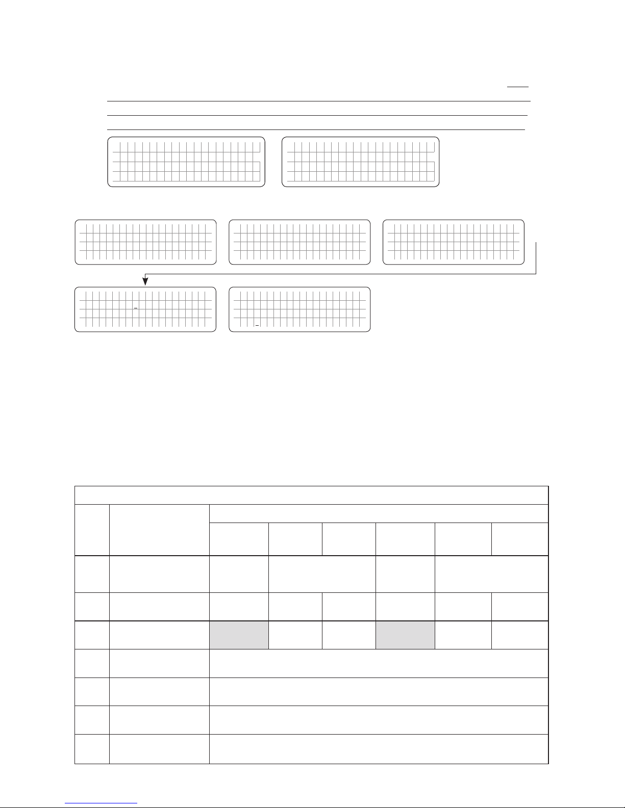
SECTION 4 | Parameter Setup
• EVOTM in Inverting Mode: Inverting will stop. EVOTM will go to Standby Mode. The
right half of the 1st Line of the Standby Mode Screens shown in the Menu Map for
Standby Mode Screens [Fig 3.1(a) and 3.1(b)] will show “Inv stop by BMS” in 2 consecutive displays - rst “Inv stop” and then “by BMS” as shown in example below:
E V O - 1 2 1 2 F I n v s t o p
O u t p u t : 0 . 0 0 V
< 0 .1 0 A
E V O - 1 2 1 2 F b y B M S
O u t p u t : 0 . 0 0 V
< 0 .1 0 A
Password 8052
See Section 4.3.1
S e l e c t G r o u p
* C H A R G E C U R V E
ð
S e l e c t P a r a m e t e r
C H A R G E C U R V E
* B U L K C U R R E N T
2 0 A
ð
S e l e c t P a r a m e t e r
C H A R G E C U R V E
* B A T T E R Y T Y P E
0 = L e a d A c i d
P a s s w o r d k e y i n
0 0 0 0
Enter Key
Down Key x 21 times Enter Key
ð
S e l e c t P a r a m e t e r
C H A R G E C U R V E
* B A T T E R Y T Y P E
0 = L e a d A c i d
4.5 GROUP 2 PARAMETER SET UP: INPUT SETTING
4.5.1 Programming Ranges and Default / Factory Preset Values of Parameters
under Group 2 - INPUT SETTING
Table 4.5 below gives details of programming ranges and default values of parameters under
Group 2 - "Select Group - INPUT SETTING". Refer to Fig 4.3 under Section 4.1.3.2 for the
Menu Map for navigating through the various parameters under this Group.
Table 4.5 Group 2 Parameter Set Up: INPUT SETTING (Refer to Menu Map at Fig 4.3, Section 4.1.3.2)
Screen
No.
Parameter
Setting range
EVO-1212F
EVO-1212F-HW EVO-2212 EVO-3012
EVO-1224F
EVO-1224F-HW EVO-2224 EVO-4024
1 DEFAULT FREQ
See NOTE
0=60Hz
(60Hz)
0=60Hz, 1=50Hz
(60Hz)
See NOTE
0=60Hz
(60Hz)
0=60Hz, 1=50Hz
(60Hz)
2 GRID MAX CURRENT
5 - 20A
(20A)
5 - 40A
(30A)
5 - 70A
(30A)
5 - 20A
(20A)
5 - 40A
(30A)
5 - 70A
(30A)
3 GEN MAX CURRENT
5 - 40A
(30A)
5 - 70A
(30A)
5 - 40A
(30A)
5 - 70A
(30A)
4 HIGH CUT OFF
50 - 70Hz
(65Hz)
5 HIGH RESET
50 - 70Hz
(64Hz)
6 LOW CUT OFF
40 - 60Hz
(55Hz)
7 LOW RESET
40 - 60Hz
(56Hz)
Enter Key
ð
See Table 4.3, Screen No. 22
for programmable options
Page 58
58 | SAMLEX AMERICA INC.
NOTES for Table 4.5:
1. Values within brackets "( )" show the Default Setting.
2. DEFAULT FREQ parameter is xed al 60Hz for EVO-1212F / 1212F-HW and EVO-1224F
/ 1224F-HW (Option 0=60Hz). If option 1 is entered, the screen line will show "!
1=xxHz" meaning that Option 1 is invalid.
3. Parameter "GEN MAX CURRENT" is not available for EVO-1212F / 1212F-HW and
EVO-1224F / 1224F-HW as separate Generator input is not available in these models.
4.5.2 Description of Parameters under Group 2 - INPUT SETTING
4.5.2.1 DEFAULT FREQ (Table 4.5, Screen No. 1)
Default frequency sets the Inverter frequency, which is also the standard frequency for AC input.
Password 8052
See Section 4.3.1
S e l e c t G r o u p
* C H A R G E C U R V E
ð
S e l e c t P a r a m e t e r
* I N P U T S E T T I N G
ð
S e l e c t P a r a m e t e r
* I N P U T S E T T I N G
D E F A U L T F R E Q
0 = 6 0 H z
P a s s w o r d k e y i n
0 0 0 0
Down Key x 1 time
Enter Key Enter Key
ð
S e l e c t P a r a m e t e r
* I N P U T S E T T I N G
D E F A U L T F R E Q
0 = 6 0 H z
NOTE: DEFAULT FREQ parameter is xed al 60Hz for EVO-1212F / 1212F-HW and
EVO-1224F / 1224F-HW (Option 0=60Hz). If option 1 is entered for these
models, the screen line will show "! 1=xxHz" meaning that Option 1 is invalid.
4.5.2.2 GRID MAX CURRENT / GEN MAX CURRENT (Table 4.5, Screen Nos. 2 & 3)
In Charging Mode, the net AC input current from the Grid/Generator is the sum of the AC
side charging current and the pass through load current. Based on the rated capacity of the
Grid Branch Circuit/Generator, the net AC input current will be required to be limited to
prevent overloading of the Grid Branch Circuit/Generator.
EVOTM Series has a very powerful battery charger that will require a proportionate higher AC
input current from the Grid/Generator. The Grid Branch Circuit/Generator will also be required
to provide current to the AC loads. The desired maximum value of input current from Grid/
Generator can be programmed (Default setting is 20A for Models EVO-1212F / 1212F-HW
/ 1224F / 1224F-HW and 30A for Models EVO-2212 / 3012 / 2224 / 4024). The EVOTM will
automatically reduce charging current to support the AC loads on priority and use whatever is
extra for charging. This will prevent overloading of the Grid Branch Circuit/Generator. If the AC
input current is over the setting value by 1A for 5 seconds, the EVOTM Inverter/Charger will stop
outputting and display an error message “Input over current!” on LCD screen. For more details,
please refer to Section 5.2.1 of the Owner's Manual for EvolutionTM Series Inverter/Charger.
SECTION 4 | Parameter Setup
ð
Enter Key
See Table 4.5, Screen No. 1
for programmable range
Page 59
4.5.2.2.1 GRID MAX CURRENT (Table 4.5, Screen No. 2)
Password 8052
See Section 4.3.1
S e l e c t G r o u p
* C H A R G E C U R V E
ð
S e l e c t P a r a m e t e r
* I N P U T S E T T I N G
ð
S e l e c t P a r a m e t e r
I N P U T S E T T I N G
* D E F A U L T F R E Q
0 = 6 0 H z
S e l e c t P a r a m e t e r
I N P U T S E T T I N G
* G R I D M A X C U R R E N T
2 0 A
Down Key x 1 time
Enter Key Down Key x 1 time
ð
P a s s w o r d k e y i n
0 0 0 0
ð
S e l e c t P a r a m e t e r
I N P U T S E T T I N G
* G R I D M A X C U R R E N T
2 0 A
Enter Key
4.5.2.3 GEN MAX CURRENT (Table 4.5, Screen No. 3)
NOTE: This parameter setting is NOT available for EVO-1212F / 1212F-HW and EVO-1224F /
1224F-HW.
Password 8052
See Section 4.3.1
S e l e c t G r o u p
* C H A R G E C U R V E
ð
S e l e c t P a r a m e t e r
* I N P U T S E T T I N G
ð
S e l e c t P a r a m e t e r
I N P U T S E T T I N G
* D E F A U L T F R E Q
0 = 6 0 H z
S e l e c t P a r a m e t e r
I N P U T S E T T I N G
* G E N M A X C U R R E N T
2 0 A
Down Key x 1 time
Enter Key
ð
P a s s w o r d k e y i n
0 0 0 0
ð
S e l e c t P a r a m e t e r
I N P U T S E T T I N G
* G E N M A X C U R R E N T
2 0 A
Enter Key
Down Key x 2 times
4.5.2.4 HIGH CUT OFF (Table 4.5, Screen No. 4)
If the AC input frequency is over the value of “HIGH CUT OFF” when in "Charging Mode",
the EVOTM Inverter/Charger will transfer to Inverting Mode.
Password 8052
See Section 4.3.1
S e l e c t G r o u p
* C H A R G E C U R V E
ð
S e l e c t P a r a m e t e r
* I N P U T S E T T I N G
ð
S e l e c t P a r a m e t e r
I N P U T S E T T I N G
* D E F A U L T F R E Q
0 = 6 0 H z
S e l e c t P a r a m e t e r
I N P U T S E T T I N G
* H I G H C U T O F F
6 5 H Z
Down Key x 1 time
Enter Key Down Key x 3 times
ð
P a s s w o r d k e y i n
0 0 0 0
ð
S e l e c t P a r a m e t e r
I N P U T S E T T I N G
* H I G H C U T O F F
6 5 H Z
Enter Key
SECTION 4 | Parameter Setup
ð
See Table 4.5, Screen No. 2
for programmable range
Enter Key
Enter Key
See Table 4.5, Screen No. 3
for programmable range
ð
Enter Key
See Table 4.5, Screen No. 4
for programmable range
ð
Page 60
60 | SAMLEX AMERICA INC.
SECTION 4 | Parameter Setup
4.5.2.5 HIGH RESET (Table 4.5, Screen No. 5)
This is the reset frequency at which the unit will revert to "Charging Mode" after it has
switched over to "Inverter Mode" due to input frequency rising above "HIGH CUT OFF".
Password 8052
See Section 4.3.1
S e l e c t G r o u p
* C H A R G E C U R V E
ð
S e l e c t P a r a m e t e r
* I N P U T S E T T I N G
ð
S e l e c t P a r a m e t e r
I N P U T S E T T I N G
* D E F A U L T F R E Q
0 = 6 0 H z
S e l e c t P a r a m e t e r
I N P U T S E T T I N G
* H I G H R E S E T
6 4 H Z
Down Key
Enter Key Down Key x 4 times
ð
P a s s w o r d k e y i n
0 0 0 0
ð
S e l e c t P a r a m e t e r
I N P U T S E T T I N G
* H I G H R E S E T
6 4 H Z
Enter Key
4.5.2.6 LOW CUT OFF (Table 4.5, Screen No. 6)
If the AC input frequency is below “LOW CUT OFF” value when in "Charging Mode", the
EVOTM Inverter/Charger will transfer to Inverting Mode.
Password 8052
See Section 4.3.1
S e l e c t G r o u p
* C H A R G E C U R V E
ð
S e l e c t P a r a m e t e r
* I N P U T S E T T I N G
ð
S e l e c t P a r a m e t e r
I N P U T S E T T I N G
* D E F A U L T F R E Q
0 = 6 0 H z
S e l e c t P a r a m e t e r
I N P U T S E T T I N G
* L O W C U T O F F
5 5 H Z
Down Key
Enter Key Down Key x 5 times
ð
P a s s w o r d k e y i n
0 0 0 0
ð
S e l e c t P a r a m e t e r
I N P U T S E T T I N G
* L O W C U T O F F
5 5 H Z
Enter Key
4.5.2.7 LOW RESET (Table 4.5, Screen No. 7)
This is the reset frequency at which the unit will revert to "Charging Mode" after it has
switched over to "Inverting Mode" due to input frequency falling below "LOW CUT OFF".
Password 8052
See Section 4.3.1
S e l e c t G r o u p
* C H A R G E C U R V E
ð
S e l e c t P a r a m e t e r
* I N P U T S E T T I N G
ð
S e l e c t P a r a m e t e r
I N P U T S E T T I N G
* D E F A U L T F R E Q
0 = 6 0 H z
S e l e c t P a r a m e t e r
I N P U T S E T T I N G
* L O W R E S E T
5 6 H Z
Down Key
Enter Key Down Key x 6 times
ð
P a s s w o r d k e y i n
0 0 0 0
ð
S e l e c t P a r a m e t e r
I N P U T S E T T I N G
* L O W R E S E T
5 6 H Z
Enter Key
Enter Key
ð
See Table 4.5, Screen No. 5
for programmable range
Enter Key
ð
See Table 4.5, Screen No. 6
for programmable range
Enter Key
ð
See Table 4.5, Screen No. 7
for programmable range
Page 61
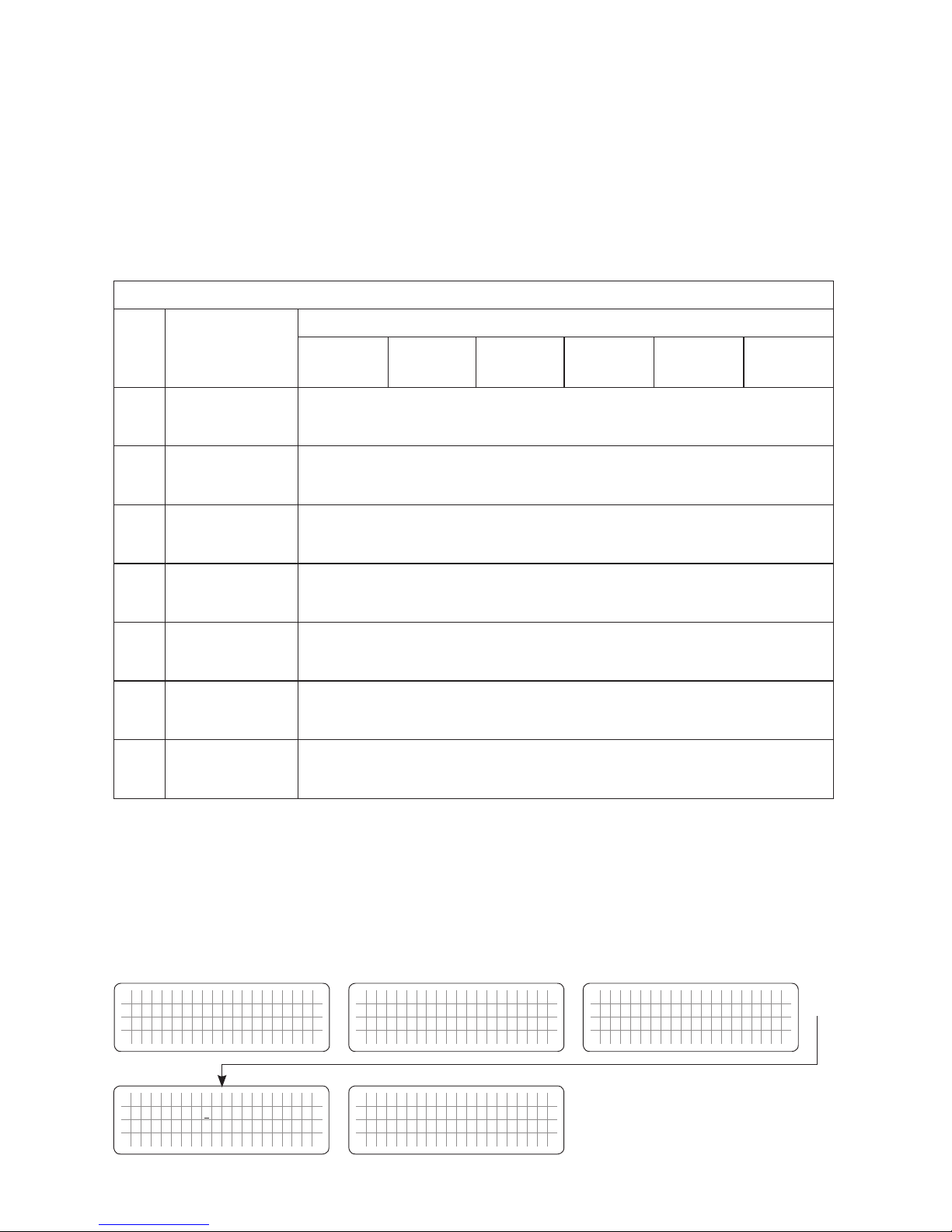
SECTION 4 | Parameter Setup
4.6 GROUP 3 PARAMETER SET UP: INPUT LOW LIMIT
4.6.1 Programming Ranges and Default / Factory Preset Values of Parameters
under Group 3 - INPUT LOW LIMIT
Table 4.6 below gives details of programming ranges and default values of parameters under
Group 3 - INPUT LOW LIMIT. Refer to Fig 4.3 under Section 4.1.3.2 for Menu Map for navigating through the various parameters under this Group.
Table 4.6 Group 3 Parameter Set Up: INPUT LOW LIMIT (Refer to Menu Map at Fig 4.3, Section 4.1.3.2)
Screen
No.
Parameter
Setting range
EVO-1212F
EVO-1212F-HW EVO-2212 EVO-3012
EVO-1224F
EVO-1224F-HW EVO-2224 EVO-4024
1 RESET VOLTAGE
60.00 - 120.0V
(105.0V)
2 CUT OFF VOLT 1
60.00 - 120.0V
(100.0V)
3 DETECT TIME 1
0 - 2000 cycles
(300 cycles)
4 CUT OFF VOLT 2
60.00 - 120.0V
(95.0V)
5 DETECT TIME 2
0 - 2000 cycles
(60 cycles)
6 CUT OFF VOLT 3
60.00 - 120.0V
(90.0V)
7 DETECT TIME 3
0 - 2000 cycles
(1 cycle)
NOTE for Table 4.6: Values within brackets "( )" show the Default Setting.
4.6.2 Description of Parameters under Group 3 - INPUT LOW LIMIT
4.6.2.1 RESET VOLTAGE (Table 4.6, Screen No. 1)
This is the reset voltage at which the unit will revert to "Charging Mode" after it has switched over to
"Inverting Mode" due to input voltage falling to "CUT-OFF VOLT 1/CUT-OFF VOLT 2/CUT-OFF VOLT3".
Password 8052
See Section 4.3.1
S e l e c t G r o u p
* C H A R G E C U R V E
ð
S e l e c t P a r a m e t e r
* I N P U T L O W L I M I T
ð
S e l e c t P a r a m e t e r
I N P U T L O W L I M I T
* R E S E T V O L T A G E
1 0 5 . 0 V
P a s s w o r d k e y i n
0 0 0 0
Down Key x 2 times
Enter Key Enter Key
ð
S e l e c t P a r a m e t e r
I N P U T L O W L I M I T
* R E S E T V O L T A G E
1 0 5 . 0 V
ð
Enter Key
See Table 4.6, Screen No. 1
for programmable range
Page 62
62 | SAMLEX AMERICA INC.
SECTION 4 | Parameter Setup
4.6.2.2 CUT OFF VOLT 1 (Table 4.6, Screen No. 2)
If during "Charging Mode", the AC input voltage falls below "CUT-OFF VOLT 1" for period >
"DETECT TIME 1", the EVOTM Inverter/Charger will transfer to Inverting Mode from "Charging Mode".
Password 8052
See Section 4.3.1
S e l e c t G r o u p
* C H A R G E C U R V E
ð
S e l e c t P a r a m e t e r
* I N P U T L O W L I M I T
ð
S e l e c t P a r a m e t e r
I N P U T L O W L I M I T
* R E S E T V O L T A G E
1 0 5 . 0 V
S e l e c t P a r a m e t e r
I N P U T L O W L I M I T
* C U T O F F V O L T 1
1 0 0 . 0 V
Down Key x 2 times
Enter Key Down Key x 1 time
P a s s w o r d k e y i n
0 0 0 0
ð
S e l e c t P a r a m e t e r
I N P U T L O W L I M I T
* C U T O F F V O L T 1
1 0 0 . 0 V
Enter Key
ð
4.6.2.3 DETECT TIME 1 (Table 4.6, Screen No. 3)
This is the time limit in cycles up to which low AC input voltage "CUT-OFF VOLT 1" is allowed.
Password 8052
See Section 4.3.1
S e l e c t G r o u p
* C H A R G E C U R V E
ð
S e l e c t P a r a m e t e r
* I N P U T L O W L I M I T
ð
S e l e c t P a r a m e t e r
I N P U T L O W L I M I T
* R E S E T V O L T A G E
1 0 5 . 0 V
S e l e c t P a r a m e t e r
I N P U T L O W L I M I T
* D E T E C T T I M E 1
3 0 0 c y c l e
Down Key x 2 times
Enter Key Down Key x 2 times
ð
P a s s w o r d k e y i n
0 0 0 0
ð
S e l e c t P a r a m e t e r
I N P U T L O W L I M I T
* D E T E C T T I M E 1
3 0 0 c y c l e
Enter Key
4.6.2.4 CUT OFF VOLT 2 (Table 4.6, Screen No. 4)
If during "Charging Mode", the AC input voltage falls below "CUT-OFF VOLT 2" for period >
"DETECT TIME 2", the EVOTM Inverter/Charger will transfer to "Inverting Mode".
Password 8052
See Section 4.3.1
S e l e c t G r o u p
* C H A R G E C U R V E
ð
S e l e c t P a r a m e t e r
* I N P U T L O W L I M I T
ð
S e l e c t P a r a m e t e r
I N P U T L O W L I M I T
* R E S E T V O L T A G E
1 0 5 . 0 V
S e l e c t P a r a m e t e r
I N P U T L O W L I M I T
* C U T O F F V O L T 2
9 5 . 0 V
Down Key x 2 times
Enter Key Down Key x 3 times
ð
P a s s w o r d k e y i n
0 0 0 0
ð
S e l e c t P a r a m e t e r
I N P U T L O W L I M I T
* C U T O F F V O L T 2
9 5 . 0 V
Enter Key
ð
Enter Key
See Table 4.6, Screen No. 2
for programmable range
ð
Enter Key
See Table 4.6, Screen No. 3
for programmable range
Enter Key
ð
See Table 4.6, Screen No. 4
for programmable range
Page 63
SECTION 4 | Parameter Setup
4.6.2.5 DETECT TIME 2 (Table 4.6, Screen No. 5)
This is the time limit in cycles up to which low AC input voltage "CUT-OFF 2" is allowed.
Password 8052
See Section 4.3.1
S e l e c t G r o u p
* C H A R G E C U R V E
ð
S e l e c t P a r a m e t e r
* I N P U T L O W L I M I T
ð
S e l e c t P a r a m e t e r
I N P U T L O W L I M I T
* R E S E T V O L T A G E
1 0 5 . 0 V
S e l e c t P a r a m e t e r
I N P U T L O W L I M I T
* D E T E C T T I M E 2
6 0 c y c l e
Down Key x 2 times
Enter Key Down Key x 4 times
ð
P a s s w o r d k e y i n
0 0 0 0
ð
S e l e c t P a r a m e t e r
I N P U T L O W L I M I T
* D E T E C T T I M E 2
6 0 c y c l e
Enter Key
4.6.2.6 CUT OFF VOLT 3 (Table 4.6, Screen No. 6)
If during "Charging Mode", the AC input voltage falls below "CUT-OFF VOLT 3" for period >
"DETECT TIME 3", the EVOTM Inverter/Charger will transfer to "Inverting Mode".
Password 8052
See Section 4.3.1
S e l e c t G r o u p
* C H A R G E C U R V E
ð
S e l e c t P a r a m e t e r
* I N P U T L O W L I M I T
ð
S e l e c t P a r a m e t e r
I N P U T L O W L I M I T
* R E S E T V O L T A G E
1 0 5 . 0 V
S e l e c t P a r a m e t e r
I N P U T L O W L I M I T
* C U T O F F V O L T 3
9 0 . 0 V
Down Key x 2 times
Enter Key Down Key x 5 times
ð
P a s s w o r d k e y i n
0 0 0 0
ð
S e l e c t P a r a m e t e r
I N P U T L O W L I M I T
* C U T O F F V O L T 3
9 0 . 0 V
Enter Key
4.6.2.7 DETECT TIME 3 (Table 4.6, Screen No. 7)
This is the time limit in cycles up to which the low AC input voltage "CUT-OFF 3" is allowed.
Password 8052
See Section 4.3.1
S e l e c t G r o u p
* C H A R G E C U R V E
ð
S e l e c t P a r a m e t e r
* I N P U T L O W L I M I T
ð
S e l e c t P a r a m e t e r
I N P U T L O W L I M I T
* R E S E T V O L T A G E
1 0 5 . 0 V
S e l e c t P a r a m e t e r
I N P U T L O W L I M I T
* D E T E C T T I M E 3
1 c y c l e
Down Key x 2 times
Enter Key Down Key x 6 times
ð
P a s s w o r d k e y i n
0 0 0 0
ð
S e l e c t P a r a m e t e r
I N P U T L O W L I M I T
* D E T E C T T I M E 3
1 c y c l e
Enter Key
Enter Key
See Table 4.6, Screen No. 5
for programmable range
ð
See Table 4.6, Screen No. 6
for programmable range
ð
Enter Key
Enter Key
See Table 4.6, Screen No. 7
for programmable range
ð
Page 64
64 | SAMLEX AMERICA INC.
SECTION 4 | Parameter Setup
4.7 GROUP 4 PARAMETER SET UP: INPUT HIGH LIMIT
4.7.1 Programming Ranges and Default / Factory Preset Values of Parameters
under Group 4 - INPUT HIGH LIMIT
TABLE 4.7 below gives details of programming ranges and default values of parameters under
Group 4 - INPUT HIGH LIMIT. Refer to Fig 4.3 under Section 4.1.3.2 for Menu Map for navigating through the various parameters under this Group.
Table 4.7 Group 4 Parameter Set Up: INPUT HIGH LIMIT (Refer to Menu Map at Fig 4.3, Section 4.1.3.2)
Screen
No.
Parameter
Setting range
EVO-1212F
EVO-1212F-HW EVO-2212 EVO-3012
EVO-1224F
EVO-1224F-HW EVO-2224 EVO-4024
1 RESET VOLTAGE
120.0 - 150.0V
(125.0V)
2 CUT OFF VOLT 1
120.0 - 150.0V
(135.0V)
3 DETECT TIME 1
0 - 2000 cycles
(60 cycles)
4 CUT OFF VOLT 2
120.00 - 150.0V
(140.0V)
5 DETECT TIME 2
0 - 2000 cycles
(15 cycles)
6 CUT OFF VOLT 3
120.0 150V
(145.0V)
7 DETECT TIME 3
0 - 2000 cycles
(1 cycle)
NOTE for Table 4.6: Values within brackets "( )" show the Default Setting.
4.7.2 Description of Parameters under Group 4 - INPUT HIGH LIMIT
4.7.2.1 RESET VOLTAGE (Table 4.7, Screen No. 1)
This is the reset voltage at which the unit will revert to "Charging Mode" after it has switched
over to "Inverting Mode" due to input AC voltage rising to "CUT-OFF VOLT 1/CUT-OFF VOLT 2/
CUT-OFF VOLT 3.
Password 8052
See Section 4.3.1
S e l e c t G r o u p
* C H A R G E C U R V E
ð
S e l e c t P a r a m e t e r
* I N P U T H I G H L I M I T
ð
S e l e c t P a r a m e t e r
I N P U T H I G H L I M I T
* R E S E T V O L T A G E
1 2 5 . 0 V
P a s s w o r d k e y i n
0 0 0 0
Down Key x 3 times
Enter Key Enter Key
ð
S e l e c t P a r a m e t e r
I N P U T H I G H L I M I T
* R E S E T V O L T A G E
1 2 5 . 0 V
ð
Enter Key
See Table 4.7, Screen No. 1
for programmable range
Page 65
SECTION 4 | Parameter Setup
4.7.2.2 CUT OFF VOLT 1 (Table 4.7, Screen No. 2)
If during "Charging Mode", the AC input voltage rises above "CUT-OFF VOLT 1" for period >
"DETECT TIME 1", the EVOTM Inverter/Charger will transfer to "Inverting Mode".
Password 8052
See Section 4.3.1
S e l e c t G r o u p
* C H A R G E C U R V E
ð
S e l e c t P a r a m e t e r
* I N P U T H I G H L I M I T
ð
S e l e c t P a r a m e t e r
I N P U T H I G H L I M I T
* R E S E T V O L T A G E
1 2 5 . 0 V
S e l e c t P a r a m e t e r
I N P U T H I G H L I M I T
* C U T O F F V O L T 1
1 3 5 . 0 V
Down Key x 3 times
Enter Key Down Key x 1 time
ð
P a s s w o r d k e y i n
0 0 0 0
ð
S e l e c t P a r a m e t e r
I N P U T H I G H L I M I T
* C U T O F F V O L T 1
1 3 5 . 0 V
Enter Key
4.7.2.3 DETECT TIME 1 (Table 4.7, Screen No. 3)
This is the time limit in cycles up to which high AC input voltage "CUT-OFF VOLT 1" is allowed.
Password 8052
See Section 4.3.1
S e l e c t G r o u p
* C H A R G E C U R V E
ð
S e l e c t P a r a m e t e r
* I N P U T H I G H L I M I T
ð
S e l e c t P a r a m e t e r
I N P U T H I G H L I M I T
* R E S E T V O L T A G E
1 2 5 . 0 V
S e l e c t P a r a m e t e r
I N P U T H I G H L I M I T
* D E T E C T T I M E 1
6 0 c y c l e
Down Key x 3 times
Enter Key Down Key x 2 times
ð
P a s s w o r d k e y i n
0 0 0 0
ð
S e l e c t P a r a m e t e r
I N P U T H I G H L I M I T
* D E T E C T T I M E 1
6 0 c y c l e
Enter Key
4.7.2.4 CUT OFF VOLT 2 (Table 4.7, Screen No. 4)
If during "Charging Mode", the AC input voltage rises above "CUT-OFF VOLT 2" for period >
"DETECT TIME 2", the EVOTM Inverter/Charger will transfer to "Inverting Mode".
Password 8052
See Section 4.3.1
S e l e c t G r o u p
* C H A R G E C U R V E
ð
S e l e c t P a r a m e t e r
* I N P U T H I G H L I M I T
ð
S e l e c t P a r a m e t e r
I N P U T H I G H L I M I T
* R E S E T V O L T A G E
1 2 5 . 0 V
S e l e c t P a r a m e t e r
I N P U T H I G H L I M I T
* C U T O F F V O L T 2
1 4 0 . 0 V
Down Key x 3 times
Enter Key Down Key x 3 times
ð
P a s s w o r d k e y i n
0 0 0 0
ð
S e l e c t P a r a m e t e r
I N P U T H I G H L I M I T
* C U T O F F V O L T 2
1 4 0 . 0 V
Enter Key
Enter Key
See Table 4.7, Screen No. 2
for programmable range
ð
Enter Key
See Table 4.7, Screen No. 3
for programmable range
ð
Enter Key
See Table 4.7, Screen No. 4
for programmable range
ð
Page 66
66 | SAMLEX AMERICA INC.
4.7.2.5 DETECT TIME 2 (Table 4.7, Screen No. 5)
This is the time limit in cycles up to which high AC input voltage "CUT-OFF VOLT 2" is allowed.
Password 8052
See Section 4.3.1
S e l e c t G r o u p
* C H A R G E C U R V E
ð
S e l e c t P a r a m e t e r
* I N P U T H I G H L I M I T
ð
S e l e c t P a r a m e t e r
I N P U T H I G H L I M I T
* R E S E T V O L T A G E
1 2 5 . 0 V
S e l e c t P a r a m e t e r
I N P U T H I G H L I M I T
* D E T E C T T I M E 2
1 5 c y c l e
Down Key x 3 times
Enter Key Down Key x 4 times
ð
P a s s w o r d k e y i n
0 0 0 0
ð
S e l e c t P a r a m e t e r
I N P U T H I G H L I M I T
* D E T E C T T I M E 2
1 5 c y c l e
Enter Key
4.7.2.6 CUT OFF VOLT 3 (Table 4.7, Screen No. 6)
If during "Charging Mode", the AC input voltage rises above "CUT-OFF VOLT 3" for period >
"DETECT TIME 3", the EVOTM Inverter/Charger will transfer to "Inverting Mode".
Password 8052
See Section 4.3.1
S e l e c t G r o u p
* C H A R G E C U R V E
ð
S e l e c t P a r a m e t e r
* I N P U T H I G H L I M I T
ð
S e l e c t P a r a m e t e r
I N P U T H I G H L I M I T
* R E S E T V O L T A G E
1 2 5 . 0 V
S e l e c t P a r a m e t e r
I N P U T H I G H L I M I T
* C U T O F F V O L T 3
1 4 5 . 0 V
Down Key x 3 times
Enter Key Down Key x 5 times
ð
P a s s w o r d k e y i n
0 0 0 0
ð
S e l e c t P a r a m e t e r
I N P U T H I G H L I M I T
* C U T O F F V O L T 3
1 4 5 . 0 V
Enter Key
4.7.2.7 DETECT TIME 3 (Table 4.7, Screen No. 7)
This is the time limit in cycles up to which high AC input voltage "CUT-OFF VOLT 3" is allowed.
Password 8052
See Section 4.3.1
S e l e c t G r o u p
* C H A R G E C U R V E
ð
S e l e c t P a r a m e t e r
* I N P U T H I G H L I M I T
ð
S e l e c t P a r a m e t e r
I N P U T H I G H L I M I T
* R E S E T V O L T A G E
1 2 5 . 0 V
S e l e c t P a r a m e t e r
I N P U T H I G H L I M I T
* D E T E C T T I M E 3
1 c y c l e
Down Key x 3 times
Enter Key Down Key x 6 times
ð
P a s s w o r d k e y i n
0 0 0 0
ð
S e l e c t P a r a m e t e r
I N P U T L O W L I M I T
* D E T E C T T I M E 3
1 c y c l e
Enter Key
SECTION 4 | Parameter Setup
Enter Key
See Table 4.7, Screen No. 5
for programmable range
ð
Enter Key
See Table 4.7, Screen No. 6
for programmable range
See Table 4.7, Screen No. 7
for programmable range
ð
Enter Key
ð
Page 67
4.8 GROUP 5 PARAMETER SET UP: OTHER FUNCTIONS
Please refer to Parameters under Group 5 at Fig 4.2. Details of Parameter set up are given below:
4.8.1 Programming Ranges and Default / Factory Preset Values of Parameters
under Group 5 - OTHER FUNCTION
Table 4.8 below gives details of programming ranges and default values of parameters under
Group 5 - OTHER FUNCTION. Refer to Fig 4.4 under Section 4.1.3.3 for Menu Map for navigating through the various parameters under this Group.
Table 4.8 Group 5 Parameter Set Up: INPUT LOW LIMIT (Refer to Menu Map at Fig 4.4, Section 4.1.3.3)
Screen
No.
Parameter
Setting range
EVO-1212F
EVO-1212F-HW EVO-2212 EVO-3012
EVO-1224F
EVO-1224F-HW EVO-2224 EVO-4024
1 POWER SAVING
0 = Disable , 1 = Enable
(0 = Disable)
2 ENTER POINT
4 - 50W
(6W)
4 - 50W
(6W)
4 - 50W
(8W)
4 - 50W
(6W)
4 - 50W
(6W)
4 - 50W
(8W)
3 WAKE UP POINT
4 - 50W
(7W)
4 - 50W
(7W)
4 - 50W
(10W)
4 - 50W
(7W)
4 - 50W
(7W)
4 - 50W
(10W)
4 REMOTE SWITCH
0 = Button Type , 1 = Switch Type
(0 = Button Type)
5 RELAY FUNCTION
0 = Charger / Other
1 = Normal / Fault
2 = Generator 0
3 = Generator 1
0 = Charger / Other
1 = Normal / Fault
2 = Generator 0
3 = Generator 1
6 COMM ID
1 - 255
(1)
7 BUZZER
0 = OFF , 1 = ON
(1 = ON)
8 DISCHARGE BEEP
0 = OFF , 1 = ON
(0 = ON)
9 DEFAULT RESET
0 = No , 1 = Yes
(0 = No)
10 DATALOG TIME
0 = Disable, 1 = 1 sec, 2 = 10 sec, 3 = 30 sec,
4 = 1 min, 5 = 5 min, 6 = 10 min
(1 = 1 sec)
11 PARAMETER SAVE
0 = No , 1 = Yes
(0 = No)
12 TEMP UNIT
0 = °C ; 1 = °F
(0 = °C)
13
PASSWORD
DISABLE
0 = No , 1 = Yes
(0 = No)
NOTES for Table 4.8:
1. Values with brackets "( )" show the Default Setting.
2. RELAY FUNCTION is not available for EVO-1212F / 1212F-HW / 1224F / 1224F-HW
SECTION 4 | Parameter Setup
Page 68
68 | SAMLEX AMERICA INC.
4.8.2 Description of Parameters under Group 5 - OTHER FUNCTION
4.8.2.1 POWER SAVING (Table 4.8, Screen No. 1)
Enable or disable Power Saving Mode when in "Inverting Mode".
Password 8052
See Section 4.3.1
S e l e c t G r o u p
* C H A R G E C U R V E
ð
S e l e c t P a r a m e t e r
* O T H E R F U N C T I O N
ð
S e l e c t P a r a m e t e r
O T H E R F U N C T I O N
* P O W E R S A V I N G
0 = D i s a b l e
Down Key x 4 times
Enter Key
P a s s w o r d k e y i n
0 0 0 0
ð
S e l e c t P a r a m e t e r
O T H E R F U N C T I O N
* P O W E R S A V I N G
0 = D i s a b l e
Enter Key
4.8.2.2 ENTER POINT (Table 4.8, Screen No. 2)
If the value of power drawn by AC load falls to the "ENTER POINT" value for 5 sec, the unit
will enter "Power Save Mode".
Password 8052
See Section 4.3.1
S e l e c t G r o u p
* C H A R G E C U R V E
ð
S e l e c t P a r a m e t e r
* O T H E R F U N C T I O N
ð
S e l e c t P a r a m e t e r
O T H E R F U N C T I O N
* P O W E R S A V I N G
0 = D i s a b l e
S e l e c t P a r a m e t e r
O T H E R F U N C T I O N
* E N T E R P O I N T
6 W
Down Key x 4 times
Enter Key Down Key x 1 time
ð
P a s s w o r d k e y i n
0 0 0 0
ð
S e l e c t P a r a m e t e r
O T H E R F U N C T I O N
* E N T E R P O I N T
6 W
Enter Key
4.8.2.3 WAKE UP POINT (Table 4.8, Screen No. 3)
If the unit is in "Power Save Mode" and the value of the AC power of the load rises to "WAKE UP
POINT", the unit will quit "Power Save Mode" and will start operating in full voltage "Inverting Mode".
Password 8052
See Section 4.3.1
S e l e c t G r o u p
* C H A R G E C U R V E
ð
S e l e c t P a r a m e t e r
* O T H E R F U N C T I O N
ð
S e l e c t P a r a m e t e r
O T H E R F U N C T I O N
* P O W E R S A V I N G
0 = D i s a b l e
S e l e c t P a r a m e t e r
O T H E R F U N C T I O N
* W A K E U P P O I N T
7 W
Down Key x 4 times
Enter Key Down Key x 2 times
ð
P a s s w o r d k e y i n
0 0 0 0
ð
S e l e c t P a r a m e t e r
O T H E R F U N C T I O N
* W A K E U P P O I N T
7 W
Enter Key
SECTION 4 | Parameter Setup
Enter Key
See Table 4.8, Screen No. 1
for programmable options
ð
Enter Key
ð
See Table 4.8, Screen No. 2
for programmable range
Enter Key
See Table 4.8, Screen No. 3
for programmable range
ð
Page 69
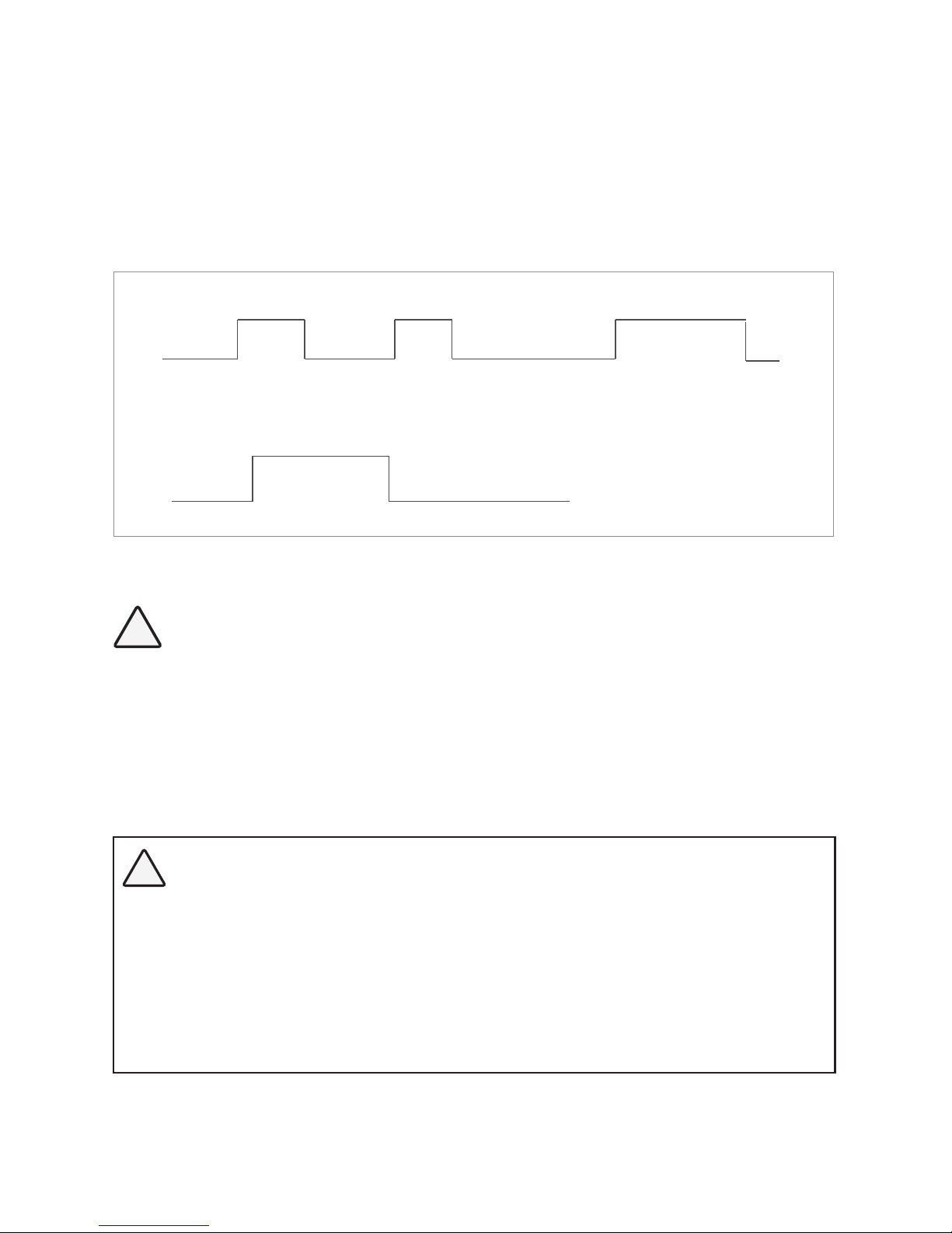
4.8.2.4 REMOTE SWITCH (Table 4.8, Screen No. 4)
This selection is used when ON/OFF control of EVOTM Inverter/Charger is desired through external
12 VDC signal fed to Remote ON/OFF terminals on the Front Panel of EVOTM Inverter/Charger
[(i)15, Fig 2.1 in EVOTM Inverter/Charger Owner's Manual for EVO-2212/3012/2224/4024 and
(ii) 16, Fig 2.1 for EVO-1212F/1212F-HW and EVO-1224F/1224-HW] On/Off Logic Diagram is
shown in Fig 4.8 below:
(i) 0 = Button Type:
External 12VDC signal is fed through Push Button Type of Switch.
•
Momentary contact of Push Button > 2 sec will switch EVO Inverter Charger ON
External +12V signal is fed through external On/Off Switch or through
relay contact closure. EVO will be ON as long as the external On/Off
switch is ON / relay contact is closed.
(ii) 1 = Switch Type:
1st 12VDC input
> 2 sec will switch ON
EVO Inverter Charger
After power ON,
12VDC input < 5 sec
will have no effect
After power ON,
12VDC input > 5 sec
will switch OFF
EVO Inverter Charger
12VDC input is
available - Power On
No 12VDC input
for 2 sec - Off
Fig 4.8. On/Off Logic Diagram for Remote Switch Options
!
CAUTION!
1. On/Off Logic shown in Fig 4.8 also controls the operation of the On/Off Button
on the front panel of EVO
TM
Inverter/Charger (11, Fig 2.1 in EVOTM Inverter/Charger
Owner's Manual). The Default Setting is "0 = Button".
2. If the On/Off control is changed to external "Remote Switch", it will not be possible to switch On/Off the EVOTM Inverter/Charger from the front panel On/Off
Push Button because it will work with Switch Type Logic at Fig 4.8: it will be ON
only as long as the Push Button is kept pressed and will switch off when released.
!
ATTENTION!
1. Logique On / Off montré dans la gure 4,8 contrôle également le fonctionnement du bouton ON/OFF sur
le panneau d’avant de l’onduleur chargeur de l' EVOTM (11 , gure 2,1 dans le manuel d'EVOTM onduleur
chargeur propriétaire ) . Le réglage par défaut est « Button Type ».
2. Si la commande de On / Off externe est changé en « l'interrupteur à distance », il ne sera pas possible
d'activer / désactiver l'onduleur/chargeur EVO
TM
à partir du panneau avant sur le bouton-poussoir On /
Off qu'il travaillera avec le type de commutateur logique à Fig 4.8 : il sera sur qu'aussi longtemps que le
bouton est maintenu enfoncé et s'éteint lorsqu'il est relâché.
SECTION 4 | Parameter Setup
Page 70
70 | SAMLEX AMERICA INC.
SECTION 4 | Parameter Setup
Password 8052
See Section 4.3.1
S e l e c t G r o u p
* C H A R G E C U R V E
ð
S e l e c t P a r a m e t e r
* O T H E R F U N C T I O N
ð
S e l e c t P a r a m e t e r
O T H E R F U N C T I O N
* P O W E R S A V I N G
0 = D i s a b l e
S e l e c t P a r a m e t e r
O T H E R F U N C T I O N
* R E M O T E S W I T C H
0 = B u t t o n
Down Key x 4 times
Enter Key Down Key x 3 times
ð
P a s s w o r d k e y i n
0 0 0 0
ð
S e l e c t P a r a m e t e r
O T H E R F U N C T I O N
* R E M O T E S W I T C H
0 = B u t t o n
Enter Key
4.8.2.5 RELAY FUNCTION (Table 4.8, Screen No. 5)
i
INFO
Menu "RELAY FUNCTION" will be displayed only for Models EVO-2212 / 3012 /
2224 / 4024 that have Generator Input Terminals. It will not be displayed for
Models EVO-1212F / 1212F-HW / 1224F / 1224F-HW.
A Single Pole Double Throw (SPDT) Status Relay with 3 contacts (Contact Rating: 3A ; 125
VAC / 30 VDC) has been provided in the Evolution
TM
Series (EVOTM) Inverter/Chargers EVO-2212
/ 3012 / 2224 / 4024 that can be used for (i) signaling of operational status (Options 0 and 1)
and (ii) providing contact closure / opening for automatic starting and stopping of generator
through appropriate optional Generator Auto Start / Stop Control Module (Options 2, 3 and
4). The 3 contacts of the Status Relay are connected to 3 terminals of Terminal Block (14, Fig
2.1 in Owner's Manual for EvolutionTM Series Models EVO-2212 / 3012 / 2224 / 4024) on the
front panel. The contacts are marked “NO” (Normally Open), “Common” and “NC” (Normally
Closed). When the Status Relay is OFF (de-energized), contacts marked “Common” and
“NO” will be in open condition and contacts marked “Common” and “NC” will be in closed
condition. When the Status Relay is ON (energized), contacts marked “Common” and “NO”
will close and contacts marked “Common” and “NC” will open.
Diagram showing steps for programming the RELAY FUNCTION parameter and details of 5
different associated Options 0 to 4 are provided in the succeeding paragraphs.
4.8.2.5.1 (a) Signaling of Operational States (Options 0 and 1)
NOTE: Applicable for Models EVO-2212 / 3012 / 2224 / 4024 ONLY.
Option 0 = Charger/Other: When the EVOTM Inverter/Charger Model EVO-2212 / 3012 / 2224
/ 4024 is in “Charging” Mode, the Status Relay will be OFF (de-energized) [(i) “Common” and
“NO” contacts will be in open condition and (ii) “Common” and “NC” contacts will be in closed
condition]. In “Other” operating modes i.e. in “Inverting”, “Power Save” or in “Standby” Modes,
the Status Relay will be ON (energized)
[(i) Common and “NO” contacts will close and (ii) “Common” and “NC” contacts will open].
Option 1 = Normal/Fault: When in “Normal” operational state i.e. when not in Fault Mode,
the Status Relay will be OFF (de-energized) [(i) “Common” and “NO” contacts will be in open
condition and (ii) “Common” and “NC” contacts will be in closed condition]. When the EVO
TM
Inverter/Charger is in “Fault” mode, the Status Relay will be ON (energized) [(i) Common and
“NO” contacts will close and (ii) “Common” and “NC” contacts will open].
Enter Key
See Table 4.8, Screen No. 4
for programmable options
ð
Page 71

SECTION 4 | Parameter Setup
4.8.2.5.1 (b) Automatic Starting and Stopping of Generator (Options 2, 3 and 4)
NOTE: Applicable for Models EVO-2212 / 3012 / 2224 / 4024 ONLY.
i
INFO
The following programmable parameters have been referred to in the description below. Links to detailed information on these parameters are given below:
• “LOW VOLT ALARM”: Please refer to Section 4.4.2.8
• “GS DETECT TIME”: Please refer to Section 4.4.2.16
• “EQUALIZE-4STAGES”: Please refer to Section 4.4.2.12
• “GEN ON TIME”: Please refer to Section 4.4.2.17
• “GEN OFF TIME”: Please refer to Section 4.4.2.18
• “RESET VOLTAGE”: Please refer to Section 4.4.2.7
The Normally Open “NO” and “Common” contacts of Status Relay (14, Fig 2.1 in the Owner's
Manual for EvolutionTM Series Inverter/Charger Models EVO-2212 / 3012 / 2224 / 4024) can be
used to also automatically start and stop generator through appropriate external Generator
Auto Start / Stop Module. 3 options (Options 2, 3 and 4) explained below are available for
carrying out this function depending upon user requirements. The “Common” and “NO”
terminals are wired to the optional Generator Auto Start / Stop Control Module which, in turn,
is wired to the Remote Start / Stop connections on the Generator. The AC output terminals
of the Generator are wired to the Generator Input Terminals on the EVOTM (7, 8, 9 in Fig 2.3 in
Owner's Manual for EVOTM Series Inverter/Charger Models EVO-2212 / 3012 / 2224 / 4024).
For installation details, please refer to Section 3.15 / Fig 3.13 and Section 3.16 / Fig 3.14 in the
Owner's Manual for EVOTM Series Inverter/Charger Models EVO-2212 / 3012 / 2224 / 4024.
i
INFO
It is recommended that “GSCM-Mini” Series of Generator Start / Stop Control Module,
appropriate for the generator to be used, may ordered directly from
Atkinson Electronics www.atkinsonelectronics.com
Based on the Generator Start Logic contained in of one of the selected Options 2, 3 or
4 explained below, the Status Relay will be switched ON (energized), its “Common” and
“NO” contacts will close and the external Generator Start / Stop Control Module will initiate
automatic starting of the Generator. Once the Generator has started and starts feeding AC
output to EVOTM (within the programmed limits of voltage and frequency), the EVOTM will be
synchronized with the Generator and once synchronization is completed, the load will be
transferred instantly (within 1 ms) to the Generator at Zero Crossing of the voltage waveform
for seamless transfer and for better protection of Transfer Relay contacts. The EVOTM will now
operate in “Charging Mode” with the AC power from the Generator charging the batteries as
well as providing power to the AC load(s).
Based on the Generator Stop Logic contained in one of the selected Options 2, 3 or 4 explained
below, the Status Relay will be switched OFF (de-energized), its “Common” and “NO” contacts
will open and the external Generator Auto Start Control Control Module will initiate automatic
stopping of the Generator. When AC output of the generator is shut down, the EVOTM will
automatically transfer the AC load(s) to the “Inverter Section” within 16 ms.
Page 72

72 | SAMLEX AMERICA INC.
SECTION 4 | Parameter Setup
Relay Options 2, 3 and 4 related to automatic starting and stopping of generator are explained below:
4.8.2.5.2(a) Option 2 = Generator 0 (This is the Default Option):
This Option will start the Generator at “LOW VOLT ALARM” and stop the Generator when the
batteries are fully charged till completion of 3-Stage Charging Cycle.
• If the battery voltage drops to “LOW VOLT ALARM” [(i) for 12V: 9.5V – 12.5V / Default 11.0V
(ii) for 24V: 19.0V – 25.0V / Default 22.0V] or lower for continuous period = “GS DETECT
TIME” (0-600 sec; Default 10 sec), the Status Relay will be energized. “Common” and “NO”
contacts of the Status Relay will close to initiate automatic starting of the Generator.
• Once the generator has started and starts feeding AC output (within the programmed
limits of voltage and frequency), the EVOTM will change over from “Inverting Mode” to
“Charging Mode”. Battery charging will be initiated as per full and complete 3-Stage
Charging Algorithm ("EQUALIZE-4STAGES", Option 0 = No).
• On entering “Float Stage” on completion of “Absorption Stage”, the Status Relay will be
switched OFF (de-energized). “Common” and “NO” contacts of the Status Relay will open to
initiate automatic stopping of the Generator. When AC output from the Generator switches
OFF, EVOTM will change over to “Inverting Mode” (NOTE: The battery will be charged to 100%
State of Charge after the Transfer Relay has de-energized on entering Float Stage).
4.8.2.5.2 (b) Option 3 = Generator 1
This Option will start the Generator at “LOW VOLT ALARM” and stop the Generator when the
batteries are charged to the desired programmed level of voltage (“RESET VOLTAGE”) and stay at
this desired level of voltage or higher for the desired programmed time period = “GEN OFF DELAY”.
• If the battery voltage drops to “LOW VOLT ALARM” [(i) for 12V: 9.5V – 12.5V / Default 11.0V (ii)
for 24V: 19.0V – 25.0V / Default 22.0V] or lower for continuous period = “GS DETECT TIME” (0600 sec; Default 10 sec), the Status Relay will be switched ON (energized). “Common” and “NO”
contacts of the Status Relay will close to initiate automatic starting of the Generator.
• Once the generator has started and starts feeding AC output (within the programmed
limits of voltage and frequency), the EVOTM will change over from “Inverting Mode” to
“Charging Mode”. Battery charging will be initiated as per full and complete 3-Stage
Charging Algorithm (“EQUALIZE-4STAGES”, Option 0 = No).
• When the batteries are charged to the desired programmed level of voltage = “RESET
VOLTAGE” [(i) for 12V: 12.0V – 17.0V / Default 14.0V (ii) for 24V: 24.0V – 35.0V / Default
28.0V] and stay at this desired level of voltage, or higher for the desired programmed
time period = “GEN OFF DELAY” (0-240 min; Default 60 min), the Status Relay will be
switched OFF (de-energized). “Common” and “NO” contacts of the Status Relay will open
to initiate automatic stopping of the Generator. When AC output from the Generator
switches OFF, EVOTM will change over to “Inverting Mode” (NOTE: The State of Charge of
the battery after the Status Relay has been switched OFF (de-energized) and Generator is
stopped will be indeterminate).
4.8.2.5.2 (c) Option 4 = Generator 2
This Option will start the Generator at “LOW VOLT ALARM” and stop the Generator after the
desired programmed value of run time of the Generator = “GEN ON TIME” (0-240 min; Default
= 60 min) counted from the time the Status Relay is switched ON (energized).
Page 73
SECTION 4 | Parameter Setup
• If the battery voltage drops to “LOW VOLT ALARM” [(i) for 12V: 9.5V – 12.5V / Default
11.0V (ii) for 24V: 19.0V – 25.0V / Default 22.0V] or lower for continuous period =
“GS DETECT TIME” (0-600 sec; Default 10 sec), the Status Relay will be switched ON
(energized). “Common” and “NO” contacts of the Status Relay will close to initiate
automatic starting of the Generator.
• Once the generator has started and starts feeding AC output (within the programmed
limits of voltage and frequency), the EVOTM will change over from “Inverting Mode” to
“Charging Mode”. Battery charging will be initiated as per full and complete 3-Stage
Charging Algorithm (“EQUALIZE-4STAGES", Option 0 = No).
• The Status Relay will be switched OFF (de-energized) after expiry of the desired
programmed Generator run time = “GEN ON TIME” (0-240 min; Default = 60 min)
counted from the time the Status Relay is switched ON (energized). “Common” and
“NO” contacts of the Status Relay will open to initiate automatic stopping of the
Generator. When AC output from the Generator switches OFF, EVOTM will change over to
“Inverting Mode” (NOTE: The State of Charge of the battery after the Status Relay has
been switched OFF (de-energized) and Generator is stopped will be indeterminate).
Diagram showing steps for programming the above RELAY FUNCTION is given below:
Password 8052
See Section 4.3.1
S e l e c t G r o u p
* C H A R G E C U R V E
ð
S e l e c t P a r a m e t e r
* O T H E R F U N C T I O N
ð
S e l e c t P a r a m e t e r
O T H E R F U N C T I O N
* P O W E R S A V I N G
0 = D i s a b l e
S e l e c t P a r a m e t e r
O T H E R F U N C T I O N
* R E L A Y F U N C T I O N
2 = G e n e r a t o r 0
Down Key x 4 times
Enter Key Down Key x 4 times
ð
P a s s w o r d k e y i n
0 0 0 0
ð
S e l e c t P a r a m e t e r
O T H E R F U N C T I O N
* R E L A Y F U N C T I O N
2 = G e n e r a t o r 0
Enter Key
4.8.2.6 COMM ID (Table 4.8, Screen No. 6)
Communication ID- This sets the ID number for the COMM Port and EVO-RC Remote Control.
Password 8052
See Section 4.3.1
S e l e c t G r o u p
* C H A R G E C U R V E
ð
S e l e c t P a r a m e t e r
* O T H E R F U N C T I O N
ð
S e l e c t P a r a m e t e r
O T H E R F U N C T I O N
* P O W E R S A V I N G
0 = D i s a b l e
S e l e c t P a r a m e t e r
O T H E R F U N C T I O N
* C O M M . I D
1
Down Key x 4 times
Enter Key Down Key x 5 times
ð
P a s s w o r d k e y i n
0 0 0 0
ð
S e l e c t P a r a m e t e r
O T H E R F U N C T I O N
* C O M M . I D
1
Enter Key
Enter Key
ð
See Table 4.8, Screen No. 5
for programmable options
Enter Key
ð
See Table 4.8, Screen No. 6
for programmable options
Page 74
74 | SAMLEX AMERICA INC.
SECTION 4 | Parameter Setup
4.8.2.7 BUZZER (Table 4.8, Screen No. 7)
Set the buzzer ON/OFF.
Password 8052
See Section 4.3.1
S e l e c t G r o u p
* C H A R G E C U R V E
ð
S e l e c t P a r a m e t e r
* O T H E R F U N C T I O N
ð
S e l e c t P a r a m e t e r
O T H E R F U N C T I O N
* P O W E R S A V I N G
0 = D i s a b l e
S e l e c t P a r a m e t e r
O T H E R F U N C T I O N
* B U Z Z E R
1 = O n
Down Key x 4 times
Enter Key Down Key x 6 times
ð
P a s s w o r d k e y i n
0 0 0 0
ð
S e l e c t P a r a m e t e r
O T H E R F U N C T I O N
* B U Z Z E R
1 = O n
Enter Key
4.8.2.8 DISCHARGE BEEP (Table 4.8, Screen No. 8)
To select the buzzer ON/OFF while in "Inverting Mode".
Password 8052
See Section 4.3.1
S e l e c t G r o u p
* C H A R G E C U R V E
ð
S e l e c t P a r a m e t e r
* O T H E R F U N C T I O N
ð
S e l e c t P a r a m e t e r
O T H E R F U N C T I O N
* P O W E R S A V I N G
0 = D i s a b l e
S e l e c t P a r a m e t e r
O T H E R F U N C T I O N
* D I S C H A R G E B E E P
0 = O f f
Down Key x 4 times
Enter Key Down Key x 7 times
ð
P a s s w o r d k e y i n
0 0 0 0
ð
S e l e c t P a r a m e t e r
O T H E R F U N C T I O N
* D I S C H A R G E B E E P
0 = O f f
Enter Key
4.8.2.9 DEFAULT RESET (Table 4.8, Screen No. 9)
This is to reset all of the parameters to the Default Values.
Password 8052
See Section 4.3.1
S e l e c t G r o u p
* C H A R G E C U R V E
ð
S e l e c t P a r a m e t e r
* O T H E R F U N C T I O N
ð
S e l e c t P a r a m e t e r
O T H E R F U N C T I O N
* P O W E R S A V I N G
0 = D i s a b l e
S e l e c t P a r a m e t e r
O T H E R F U N C T I O N
* D E F A U L T P R E S E T
0 = N o
Down Key x 4 times
Enter Key Down Key x 8 times
ð
P a s s w o r d k e y i n
0 0 0 0
ð
S e l e c t P a r a m e t e r
O T H E R F U N C T I O N
* D E F A U L T P R E S E T
0 = N o
Enter Key
4.8.2.10 DATALOG TIME AND DATALOG DISABLE (Table 4.8, Screen No. 10)
Refer to Sections 5.2 to 5.3 on Data Logging. There are 25 Data Fields in Model Nos. EVO1212F / 1212F-HW / 1224F / 1224F-HW and 28 Data Fields in Model Nos. EVO-2212 / 3012
/ 2224 / 4024 that can be logged in external SD Card (Refer to Section 5.2.2 and 5.2.3 for
details of the Data Fields). A Real Time Clock inside the EVO-RC-PLUS Remote Control records
Enter Key
See Table 4.8, Screen No. 7
for programmable options
ð
Enter Key
See Table 4.8, Screen No. 8
for programmable options
ð
Enter Key
See Table 4.8, Screen No. 9
for programmable options
ð
Page 75
SECTION 4 | Parameter Setup
timing. Time interval between recordings (called “DATALOG TIME”) is programmable. “Events”
and “Errors” are recorded as soon as they are sensed. In the default setting, Data Logging is
enabled. Data Logging can be disabled by setting programming option “0=Disable”.
Programming options and procedure are shown below:
Programming Options (i) 0=Disable, (ii) 1=1 sec (Default), (iii) 2=10 sec, (iv) 3=30 sec,
(iv) 4=60 sec, (vi) 5=5 min, (vii) 6=10 min
Password 8052
See Section 4.3.1
S e l e c t G r o u p
* C H A R G E C U R V E
ð
S e l e c t P a r a m e t e r
* O T H E R F U N C T I O N
ð
S e l e c t P a r a m e t e r
O T H E R F U N C T I O N
* P O W E R S A V I N G
0 = D i s a b l e
S e l e c t P a r a m e t e r
O T H E R F U N C T I O N
* D A T A L O G T I M E
1 = 1 s e c
Down Key x 4 times
Enter Key Down Key x 9 times
ð
P a s s w o r d k e y i n
0 0 0 0
ð
S e l e c t P a r a m e t e r
O T H E R F U N C T I O N
* D A T A L O G T I M E
1 = 1 s e c
Enter Key
4.8.2.11 PARAMETER SAVE (Table 4.8, Screen No. 11)
Save all parameters to SD Card. (see Details at Section 5.4)
Password 8052
See Section 4.3.1
S e l e c t G r o u p
* C H A R G E C U R V E
ð
S e l e c t P a r a m e t e r
* O T H E R F U N C T I O N
ð
S e l e c t P a r a m e t e r
O T H E R F U N C T I O N
* P O W E R S A V I N G
0 = D i s a b l e
S e l e c t P a r a m e t e r
O T H E R F U N C T I O N
* P A R A M E T E R S A V E
0 = N o
Down Key x 4 times
Enter Key Down Key x 10 times
ð
P a s s w o r d k e y i n
0 0 0 0
ð
S e l e c t P a r a m e t e r
O T H E R F U N C T I O N
* P A R A M E T E R S A V E
0 = N o
Enter Key
4.8.2.12 TEMP UNIT (Table 4.8, Screen No. 12)
Temperature display can be selected in °C or °F. Default is in °C.
Password 8052
See Section 4.3.1
S e l e c t G r o u p
* C H A R G E C U R V E
ð
S e l e c t P a r a m e t e r
* O T H E R F U N C T I O N
ð
S e l e c t P a r a m e t e r
O T H E R F U N C T I O N
* P O W E R S A V I N G
0 = D i s a b l e
S e l e c t P a r a m e t e r
O T H E R F U N C T I O N
* T E M P U N I T
0 = C
Down Key x 4 times
Enter Key Down Key x 11 times
ð
P a s s w o r d k e y i n
0 0 0 0
ð
S e l e c t P a r a m e t e r
O T H E R F U N C T I O N
* T E M P U N I T
0 = C
Enter Key
Enter Key
ð
See Table 4.8, Screen No. 10
for programmable range
Enter Key
See Table 4.8, Screen No. 11
for programmable options
ð
Enter Key
See Table 4.8, Screen No. 12
for programmable options
ð
Page 76
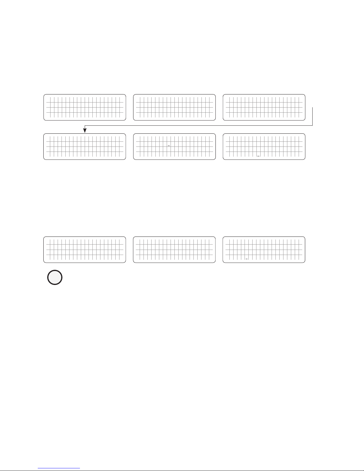
76 | SAMLEX AMERICA INC.
SECTION 4 | Parameter Setup
4.8.2.13 PASSWORD DISABLE (Table 4.8, Screen No. 13)
In default condition, Password (8052) is required to change the value of programmable parameter. Use of Password prevents accidental change of parameter setting.
Password may be disabled, if required.
Password 8052
See Section 4.3.1
S e l e c t G r o u p
* C H A R G E C U R V E
ð
S e l e c t P a r a m e t e r
* O T H E R F U N C T I O N
ð
S e l e c t P a r a m e t e r
O T H E R F U N C T I O N
* P O W E R S A V I N G
0 = D i s a b l e
S e l e c t P a r a m e t e r
O T H E R F U N C T I O N
* P A S S W O R D D I S A B L E
0 = N o
Down Key x 4 times
Enter Key Down Key x 12 times
ð
P a s s w o r d k e y i n
0 0 0 0
ð
S e l e c t P a r a m e t e r
O T H E R F U N C T I O N
* P A S S W O R D D I S A B L E
0 = N o
Enter Key
4.9 GROUP 6 PARAMETER SETUP: TIME SETTING
Please refer to Parameter "TIME SETTING" under Screen No. 6 for Group 6 at Fig 4.1. Set up details are given below. The Date and Time Format is Year/Month/Day Hour:Minute (24 hour clock):
NOTE: Password is not required for setting this parameter.
S e l e c t G r o u p
* C H A R G E C U R V E
ð
S e l e c t G r o u p
* T I M E S E T T I N G
ð
S e l e c t P a r a m e t e r
T I M E S E T T I N G
E n t e r t h e t i m e
2 0
0 0 / 0 1 / 0 1 0 : 0 0
Down Key x 5 times
Enter Key
i
INFO
• Time can be programmed from Year 2000 to 2099 only.
• Month can be programmed from 01 to 12 only.
• Day can be programmed from 01 to 31 only.
• Hour can be programmed from 00 to 24 only.
• Minute can be programmed from 00 to 60 only.
• If the numbers Entered for Month, Day, Hour and Minute are not within
the above ranges, message "OUT OF RANGE!" will be displayed and the
display screen will go back to the previously set time. Setting procedure
will have to be re-started.
4.10 GROUP 7 PARAMETER SETUP: STOP SD CARD
Please refer to Parameter "STOP SD CARD" under Group 7 at Fig 4.2. Please note that this
set up is displayed / accessible only when SD Card is inserted in the SD Card Slot (9, Fig 1.1a).
Set up details are given below:
Once SD Card is being used, it should be removed/ejected only after the operation of the
Card has been stopped as shown below and message "Please remove SD Card" appears. If
the SD card is not removed within 30 sec, it will reset. After the card is removed, it reverts to
the original operating screen.
Enter Key
See Table 4.8, Screen No. 13
for programmable options
ð
Page 77
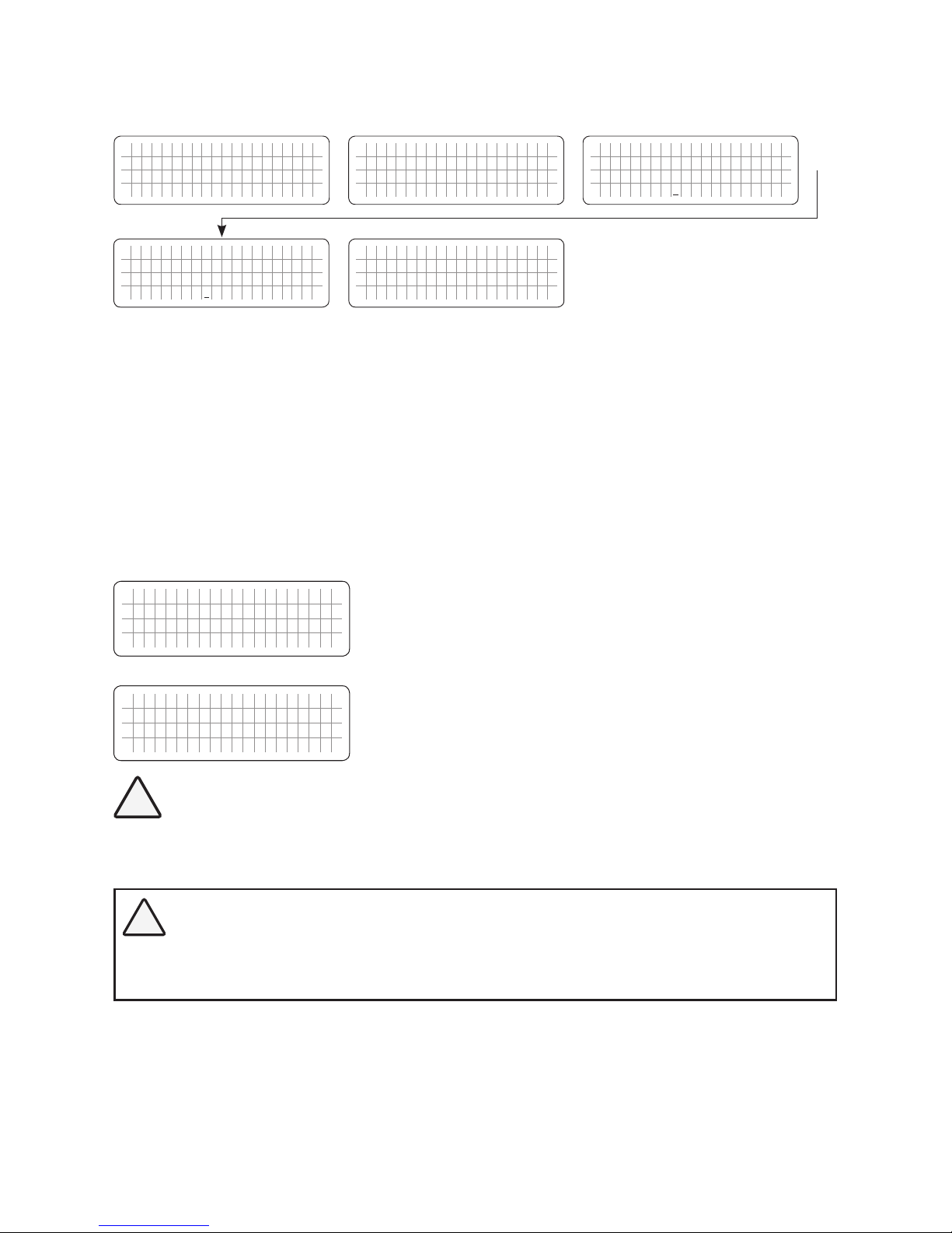
SECTION 4 | Parameter Setup
If SD Card is not
removed within 30 sec,
the unit will reset.
S e l e c t G r o u p
* C H A R G E C U R V E
ð
S e l e c t G r o u p
* S T O P S D C A R D
ð
S e l e c t P a r a m e t e r
S T O P S D C A R D
0 = N o
S e l e c t P a r a m e t e r
S T O P S D C A R D
1 = Y e s
Down Key x 6 times
Enter Key Down Key x 1 time
ð
P l e a s e r e m o v e
S D C a r d
Enter Key
SECTION 5 | SD Card
5.1 SD CARD GENERAL INFORMATION
SD Card slot has been provided for using an SD card for (i) data logging and (ii) saving programmed parameters. SD card supports FAT16/FAT32 format up to 16GB in size.
When the SD card is inserted, the LCD screen will display the following.
S D C a r d d e t e c t e d
V 2 . X H C 4 G B
SD card is detected and shows the Version and capacity. "xx" is
the capacity.
S D C a r d
u n u s a b l e !
Not supported card.
!
CAUTION!
Do not remove SD Card when data logging has been enabled (may corrupt les).
Follow "STOP SD CARD" procedure (Section 4.10) before removing the SD Card.
!
ATTENTION!
Ne pas retirer la carte SD lorsque « data loggin » a été activée (peut corrompue les chiers). Suivez la procé-
dure "STOP SD CARD" (article 4.10 ) avant de retirer la carte SD .
ð
Page 78
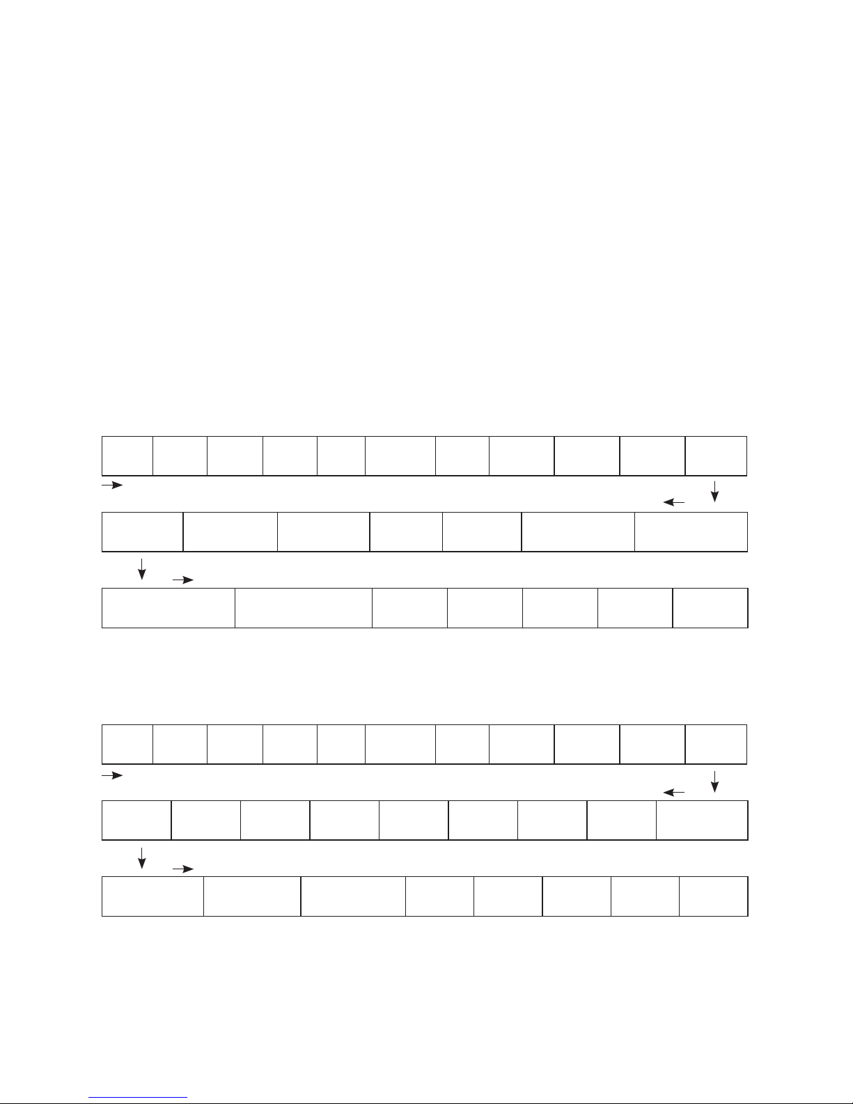
78 | SAMLEX AMERICA INC.
5.2 DATA LOGGING
As mentioned at Section 5.1 above, external SD Card may be used to log operating information.
• When the SD Card is inserted in the SD Card Slot, data logging is activated automatically
(it will be disabled only if programmable setting has been changed to “0=Disable)
A Real Time Clock inside the EVO-RC Remote Control records timing. Time interval between
recordings (called “DATALOG TIME”) is programmable. Refer to Section 4.8.2.10 for
programming details. Available options for “DATALOG TIME” are:
• 0=Disable ; 1=1 sec (Default); 2=10 sec; 3=30 sec; 4=60 sec; 5=5 min; 6=10 min
• “Events” and “Error Codes” are recorded as soon as they are sensed.
5.2.2 DATA LOGGING Fields for Models EVO-1212F / 1212F-HW / 1224F /
1224F-HW
The following 25 Data Fields consisting of various electrical parameters, events and error codes
are recorded for Models EVO-1212F/1212F-HW/1224F/1224F-HW:
Date Time
Grid
status
Grid
freq
Grid
volt
Input
current
Input VAInputt
watt
Output
freq
Output
Volt
Output
current
Output VA Output watt Battery volt
Battery
current
External
current
Battery
temperature (C)
Transformer
temperature (C)
Hear sink
temperature 1 (C)
Hear sink
temperature 2 (C)
Fan
speed
Mode
Error
code
Charge
stage
Event
5.2.3 DATA LOGGING Fields for Models EVO-2212 / 3012 / 2224 / 4024
The following 28 Data Fields consisting of various electrical parameters, events and error codes
are recorded for Models EVO-2212 / 3012 / 2224 / 4024:
Date Time
Gen
status
Gen
freq
Gen
volt
Grid
status
Grid
freq
Grid
volt
Input
current
Input
VA
Inputt
watt
Output
freq
Output
Volt
Output
current
Output VAOutput
watt
Battery
volt
Battery
current
External
current
Battery
temperature
Transformer
temperature
Busbar
temperature
Heat sink
temperature
Fan
speed
Mode
Error
Code
Charge
stage
Event
SECTION 5 | SD Card
Page 79
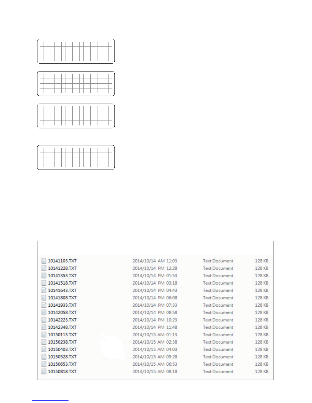
F i l e c r e a t i n g . . .
Data log function has been initiated and new le is being
created. Do not remove the SD card when le creating is
displayed.
S D C a r d
e r r o r !
Read error, the data log function/update/upload will stop.
S D C a r d
W r i t e e r r o r !
Write error. The Data logging function will stop.
S D C a r d f u l l !
1. Card full. Data logging function has stopped.
2. There is not enough space to create Data Log File Folder
or to save le with saved programmed parameters.
NOTE: Once there is enough space to create a Data Log
File Folder and subsequently, it runs out of capacity due to
recording newer data, it will start to overwrite on older les.
5.3 DATA LOG FILES AND VIEWING DATA LOG FILES USING MICROSOFT EXCEL
The Data Log Files are written as Text Files (.txt) in the DATALOG Folder on the SD Card’s Root
Directory. Table 5.1 is an image of the DATALOG Folder showing example of the Data Log Files.
The File Name Format is month/day/hour/minute.txt (MMDDhhmm.txt). Each le has 512 rows
of records (Each row has multiple data elds as described at Section 5.2.2 and 5.2.3). Each le
size is 128KB.
Table 5.1 Example of Data Log Folder in SD Card's Root Directory
SECTION 5 | SD Card
Page 80
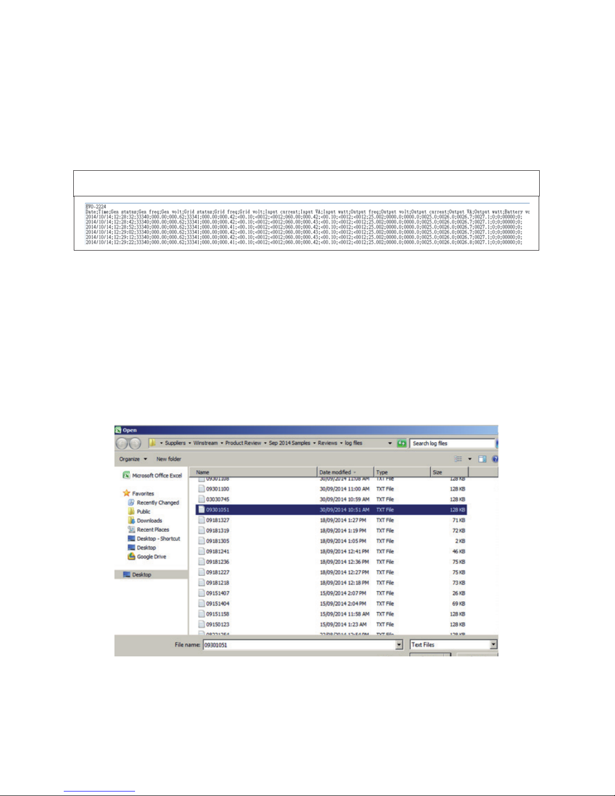
80 | SAMLEX AMERICA INC.
Table 5.2 shows an example of one of the File’s contents opened with a general purpose Text
Reader. The 1st Row shows the Model No. of the EVOTM.The 2nd Row shows Data elds separated by semicolon i.e. ";" (see details of the Data elds at Section 5.2.2 and 5.2.3). The 3rd
Row onwards shows the status of the Data Fields at time interval equal to the programmed
value of DATALOG TIME (See Section 4.8.2.10).
NOTE: Event / Error Code will be logged as soon as they occur.
TABLE 5.2 Contents of Data Log File
Follow procedure given below to open Data Log Files in Microsoft Ofce Excel:
• Start Microsoft Ofce Excel.
• Click File Microsoft Ofce Button on the top left hand corner.
• Click "Open" from the Drop Down Menu.
• Navigate to the Directory where the Log Files downloaded from the SD Card are located.
• Click on "File Types"selection button at the bottom right corner (shows "All Excel Files"
as default) and select Text les from the Drop Down Menu.
• All Text Files (.txt) will be displayed. The screen will look like Fig 5.1.
Fig 5.1 Screen Showing .txt Files
• Click "Open" Button (Bottom right corner of Fig 5.1).
• Text Import Wizard – Step 1 will be shown (Fig 5.2). Choose "Delimited"File Type".
SECTION 5 | SD Card
Page 81
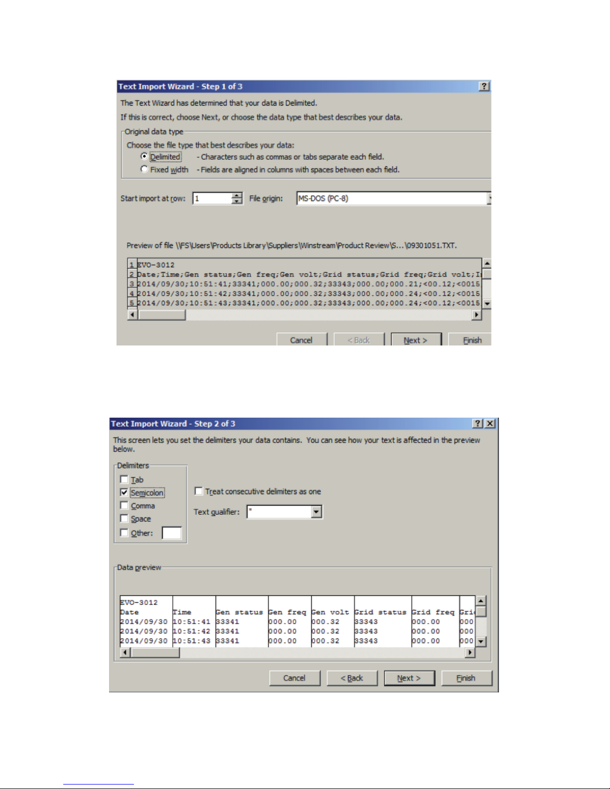
SECTION 5 | SD Card
Fig 5.2 Screen Shot of Step 1 of "Text Import Wizard" in Excel
• Text Import Wizard – Step 2 will appear (see Fig 5.3). Choose "Semicolon" and click 'Finish'
button.
Fig 5.3 Screen Shot of Step 2 of "Text Import Wizard" in Excel
Page 82
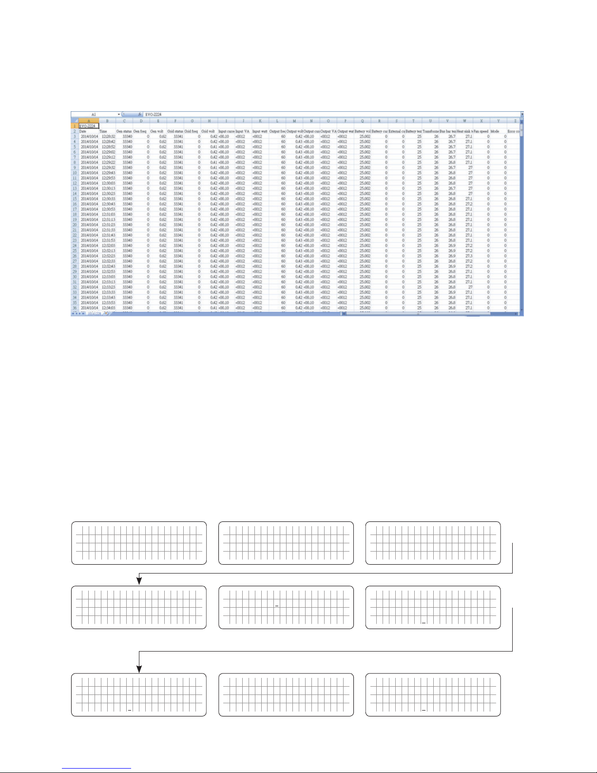
82 | SAMLEX AMERICA INC.
• Data as in Fig 5.4 will be displayed on your Worksheet, with the Log Data stored in
Columns and Rows.
Fig 5.4 Screen Shot and Data Log Work Sheet
5.4 SAVING / UPLOADING PROGRAMMED PARAMETERS
5.4.1 Saving Programmed Parameters
All the programmed parameters can be saved on an SD Card (FAT 16 / FAT 32 Format, up to
16 GB capacity). The parameters will be saved in File named “xxxx_yyy.cfg”, where the rst
group of 4 digits xxxx is the Model No. e.g. 1212F or 1224F or 2212 or 2224 or 3012 or
4024 and the second group of 3 digits YYY is the Revision No. for that Model e.g. 074.
• For saving, rst insert the SD Card in the SD Card Slot.
• Then, go to “Parameter Save” Screen (See Table 4.8 and Section 4.8.2.11) – under
heading "PARAMETER SAVE"). Steps are given below:
Password 8052
See Section 4.3.1
S e l e c t G r o u p
* C H A R G E C U R V E
ð
S e l e c t P a r a m e t e r
* O T H E R F U N C T I O N
ð
S e l e c t P a r a m e t e r
O T H E R F U N C T I O N
* P O W E R S A V I N G
0 = D i s a b l e
S e l e c t P a r a m e t e r
O T H E R F U N C T I O N
* P A R A M E T E R S A V E
0 = N o
Down Key x 4 times
Enter Key Down Key x 10 times
ð
P a s s w o r d k e y i n
0 0 0 0
ð
S e l e c t P a r a m e t e r
O T H E R F U N C T I O N
* P A R A M E T E R S A V E
0 = N o
Enter Key
S e l e c t P a r a m e t e r
O T H E R F U N C T I O N
P A R A M E T E R S A V E
1 = Y e s
ð
S a v e d f i l e e n d .
ð
S e l e c t P a r a m e t e r
O T H E R F U N C T I O N
* P A R A M E T E R S A V E
0 = N o
Down Key
Press Enter Key, hold for
3 to 4 sec and release
SECTION 5 | SD Card
Enter Key
Enter Key
ð
ð
Page 83
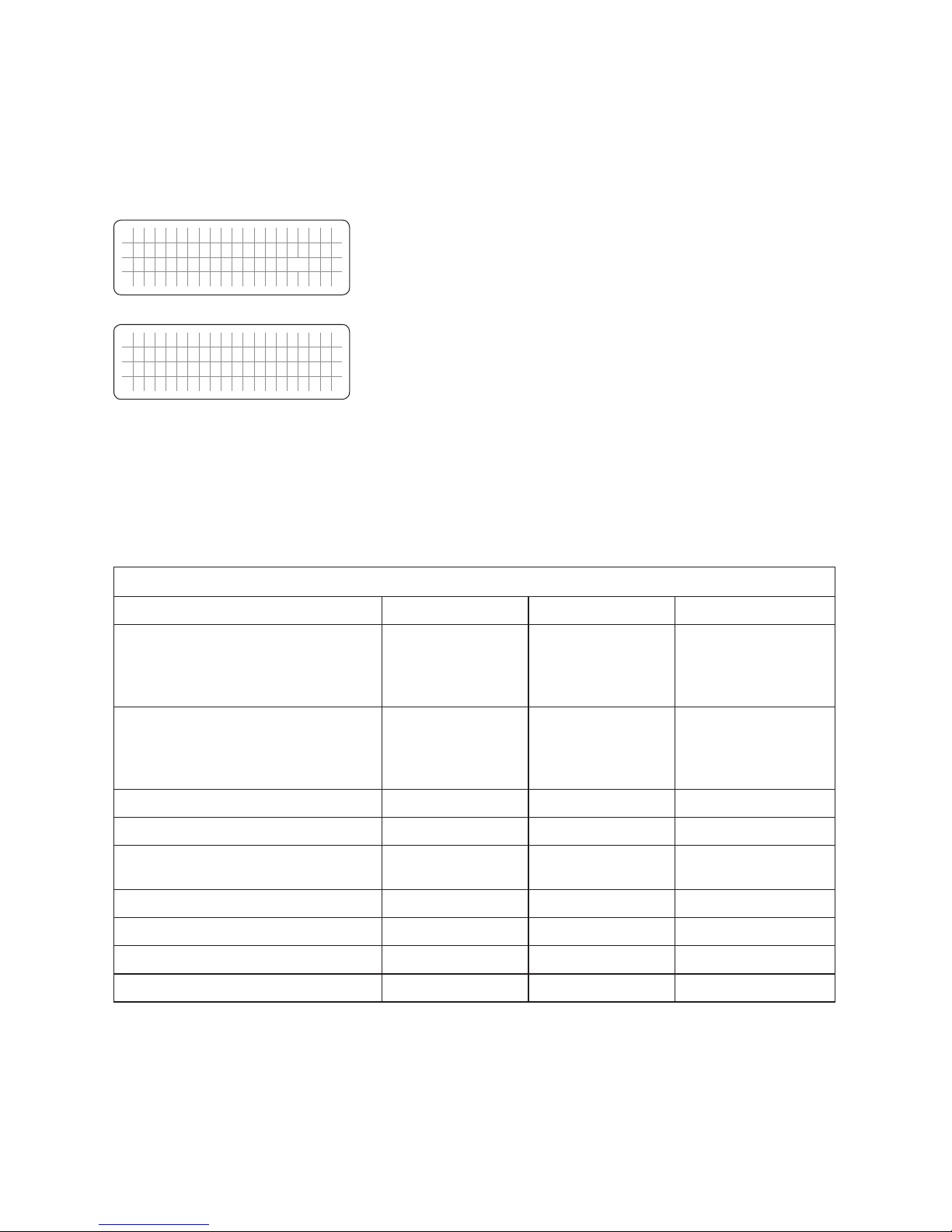
5.4.2 Uploading Saved Parameters
If there is a “xxxx_yyy.cfg” le in the SD card with stored programmed parameters, then on
inserting the card, the Remote Control will ask to upload the Cong File. Press Enter Button
to conrm or Back Key to cancel.
U p l o a d c o n f ?
Y e s = E n t e r k e y
N o = B a c k k e y
• Asks to conrm or cancel uploading of saved parameters.
• Choose Yes by pressing Enter Key.
U p l o a d c o n f
1 %
Conguration uploading.
SECTION 6 | Monitoring of Operation
Using LED and Buzzer
TABLE 6.1 LED & BUZZER INDICATIONS FOR OPERATION MONITORING
Status Blue LED "Status" Red LED "Fault" Buzzer (See Note 1)
Seen during Power-On Sequence
Indicates completion of Power-On
Sequence after Power ON/OFF Button
is pressed for 2 sec
Blink 3 times OFF OFF
Seen during Power-Off Sequence
Indicates completion of Power-Off
Sequence after Power ON/OFF Button
is pressed for 5 sec
ON ON OFF
Normal charging Blink once per sec OFF OFF
Equalization charging Blink twice per sec OFF OFF
Inverting ON OFF
Beep per 3 second
(Default OFF)
Low battery alarm ON Blink once per sec Beep per second
Power saving Blink once per 3 sec OFF OFF
Standby Blink once per 5 sec OFF OFF
Fault OFF ON ON
NOTE: Buzzer is available only in EVOTM Inverter/Charger. There is no buzzer in Remote Control
EVO-RC-PLUS.
SECTION 5 | SD Card
Page 84

84 | SAMLEX AMERICA INC.
TABLE 7.1 FAULT MESSAGES AND TROUBLESHOOTING GUIDE
NOTES: 1. Please see Table 6.1 for LED indications in EVO-RC and buzzer indications in EVOTM Inverter/Charger
2. Buzzer is available only in EVOTM Inverter/Charger. There is no buzzer in Remote Control EVO-RC
Fault Message Symptoms and Trouble Shooting
Battery low voltage!
• EVO
TM
Inverter/Charger is in FAULT MODE because the battery voltage has dropped to
the set lower threshold of “BATT LOW VOLTAGE”
• When the battery voltage drops to the set lower threshold of “BATT LOW VOLTAGE”,
activation of this fault protection is initiated. The Red LED marked “Fault” will ash once
per second and the buzzer in EVOTM Inverter/Charger will beep once per second. The
Inverter Section will continue to operate normally and the Blue LED marked “Status”
will continue to be ON steady (NOTE: Fault message “Battery low voltage!” will not be
displayed during this time)
• If the battery voltage stays at or below the above threshold for duration equal to the set “LV
DETECT TIME”, only the Inverter Section will be switched OFF and fault message “Battery
low voltage!” will be displayed. The Red LED marked “Fault” will now change to steady
ON, the Blue LED marked “Status” will switch OFF and the buzzer in EVO
TM
Inverter/Charger
will now beep steady. If the “Battery low voltage!” fault condition is not reset within the “LV
CUT OFF TIME”, EVO
TM
Inverter/Charger will be shut down completely after the expiry
of “LV CUT OFF TIME” (LCD Display / LED / Buzzer will be OFF).
• If the batteries are charged by external charger connected directly to the batteries or
through the External Charger Input (3, 4 in Fig 2.1 in EVO
TM
Inverter/Charger Manual)
and the battery voltage recovers to the set “RESET VOLTAGE” before the expiry of “LV
CUT OFF TIME” while in “Battery low voltage!” fault condition, the Inverter Section will
restart and “Battery low voltage!” fault condition will be cleared.
• While in “Battery low voltage!” fault condition, if AC input is made available before the
expiry of “LV CUT OFF TIME”, the “Battery low voltage!” fault condition will be cleared.
The EVOTM Inverter/Charger will restart in Inverter Mode, synchronize with the AC input
and then, transfer to the AC input at zero crossing. It will now operate in Charging Mode
Battery ultra
low voltage!
• EVO
TM
Inverter/Charger is in FAULT MODE because the battery voltage has dropped to 9V
or lower for the 12VDC input Models EVO-1212F / 1212F-HW / 2212 / 3012 or to 18 V or
lower for the 24 VDC input Models EVO-1224F / 1224F-HW / 2224 / 4024.
• When the battery voltage drops to 9V or lower for the 12 VDC version of EVOTM Inverter/
Charger or 18V or lower for the 24 VDC version, only the Inverter Section will be switched
OFF and message “Battery ultra low voltage!” will be displayed. Red LED marked
“Fault” will be steady ON, the Blue LED marked “Status” will be switched OFF and the
buzzer in EVOTM Inverter/Charger will beep steady.
• When the duration in “Battery ultra low voltage!” fault condition is equal to the set
duration of “LV DETECT TIME”, the message will change to “Battery low voltage!” If
“Battery low voltage!” fault condition is not reset within the “LV CUT OFF TIME”, EVOTM
Inverter/Charger will be shut down completely after the expiry of “LV CUT OFF
TIME” (LCD Display / LED / Buzzer will be OFF).
• If the batteries are charged by external charger connected directly to the batteries or
through the External Charger Input (3, 4 in Fig 2.1 in EVOTM Inverter/Charger Manual)
and the battery voltage recovers to the set “RESET VOLTAGE” before the expiry of “LV
CUT OFF TIME” while in “Battery low voltage!” fault condition, the Inverter Section will
restart and “Battery low voltage!” fault condition will be cleared.
• While in “Battery low voltage!” fault condition, if AC input is made available before the
expiry of “LV CUT OFF TIME”, the “Battery low voltage!” fault condition will be cleared.
The EVOTM Inverter/Charger will restart in Inverter Mode, synchronize with the AC input
and then, transfer to the AC input at zero crossing. It will now operate in Charging Mode
SECTION 7 | Fault Messages and
Troubleshooting Guide
Page 85

Battery over voltage!
EVOTM Inverter/Charger is in FAULT MODE because the battery voltage has risen to the set
upper threshold of “BATT OVER VOLTAGE”
(a) AC input is not available and EVOTM Inverter/Charger is operating in Inverting Mode:
• There will be no AC output because the Inverter Section will be switched OFF. The Blue
LED marked “Status” will be switched OFF and the Red LED marked “Fault” will be
steady ON. The buzzer in EVOTM Inverter/Charger will beep steady
• The fault will be cleared automatically when the battery voltage drops to 0.5V below
the set upper threshold of “BATT OVER VOLT”
(b) AC input is available and EVOTM Inverter/Charger is operating in Charging Mode:
• There will be no AC output or charging because the Transfer Relay will be de-energized
and PWM drive to the Inverter Section will be switched OFF.
• The fault will be cleared automatically when the battery voltage drops to 0.5V below to the
set upper threshold of “BATT OVER VOLT”. The EVOTM Inverter/Charger will restart in Inverting
Mode, synchronize with the AC input and then, the Transfer Relay will be energized to transfer
to AC input at zero crossing. The unit will, thus, resume operation in “Charging Mode”
Input over current!
EVO
TM
Inverter/Charger is in FAULT MODE because the input current being drawn from the
AC input source (Input current = Charging Current + Pass Through Current to the load) is 1A
more than the set threshold of “ GRID MAX CURRENT” / "GEN MAX CURRENT"
for 5 seconds (current is sampled every 33.3 µs).
• There will be no AC output because the Transfer Relay will be de-energized, charging will
be stopped and PWM drive to the Inverter Section will be switched OFF. The Blue LED
marked “Status” will be switched OFF and the Red LED marked “Fault” will be steady ON.
The buzzer in EVOTM Inverter/Charger will beep steady
• EVOTM Inverter/Charger will be latched in OFF condition and will require manual reset
by powering OFF, waiting for 1 minute and then powering ON again
• The set threshold of “ GRID MAX CURRENT” / "GEN MAX CURRENT" (Section 4.5.2.2)
should match the breaker capacity of the AC input source / AC input Branch Circuit. If
AC input current capacity cannot be increased, reduce the AC load / “BULK CURRENT”
(Section 4.4.2.1) accordingly.
Output over current!
EVO
TM
Inverter/Charger is in FAULT MODE because the instantaneous output current
being drawn by the AC load in Inverting Mode is 330% of the rated value of the EVO
TM
Inverter/Charger for 2 samples (current is sampled every 33.3 µs).
• There will be no AC output because the Inverter Section will be switched OFF. The Blue
LED marked “Status” will be switched OFF and the Red LED marked “Fault” will be
steady ON. The buzzer in EVO
TM
Inverter/Charger will beep steady
• EVO
TM
Inverter/Charger will be latched in OFF condition and will require manual
reset by powering OFF, waiting for 1 minute and then powering ON again
• Ensure that the maximum instantaneous surge current of the load is not more than
300% of the rated current of the EVO
TM
Inverter/Charger for 1 millisecond
EVO
TM
Inverter/Charger is in FAULT MODE because of overload conditions in Inverting Mode:
• There will be no AC output because the Inverter Section will be switched OFF. The Blue
LED marked “Status” will be switched OFF and the Red LED marked “Fault” will be
steady ON. The buzzer in EVOTM Inverter/Charger will beep steady
• EVOTM Inverter/Charger will be latched in OFF condition and will require manual
reset by powering OFF, waiting for 1 minute and then powering ON again
• Ensure that overloading is limited to the specied limit
Output over load!
Output voltage is less than 96Vrms for 300 cycles (5 seconds at 60Hz)
Output over load 1!
Output power is over the Power Boost Rating: 110% for 30 min
Output over load 2!
Output power is over the Power Boost Rating:
• 120% for 10 min for EVO-1212F / 1212F / 1224F / 1224F-HW
• 120% for 5 min for EVO-2212 / 3012 / 2224 / 4024
Output over load 3!
Output power is over the Power Boost Rating:
• 140% for 1 min for EVO-1212F / 1212F / 1224F / 1224F-HW
• 140% for 30 sec for EVO-2212 / 3012 / 2224 / 4024
Output over load 4!
Output power is over the Power Boost Rating:
• 150% for 30 sec for EVO-1212F / 1212F / 1224F / 1224F-HW
• 150% for 5 sec for EVO-2212 / 3012 / 2224 / 4024
SECTION 7 | Fault Messages and
Troubleshooting Guide
Page 86

86 | SAMLEX AMERICA INC.
Fault Message Symptoms and Trouble Shooting
Output short circuit!
EVO
TM
Inverter/Charger is in FAULT MODE because there is a short circuit on the output
side in Inverter Mode. Short circuit protection is activated when: (i) EVO-1212F/1212F-
HW/1224F/1224F-HW: Output voltage is < 15Vrms for 6 cycles and output current is > the
rated output current of 10.00Arms, (ii) EVO-2212/2224: Output voltage is < 15Vrms for 6
cycles and output current is > the rated output current of 18.33Arms (iii) EVO-3012: Output
voltage is < 15Vrms for 6 cycles and output current is > the rated output current of 25.00Arms
and (iv) EVO-4024: Output voltage is < 15Vrms for 6 cycles and output current is > the rated
output current of 33.33Arms
• There is no AC output because the Inverter Section has been switched OFF. The Blue
LED marked “Status” will be switched OFF and the Red LED marked “Fault” will be
steady ON. The buzzer in EVOTM Inverter/Charger will beep steady
• EVOTM Inverter/Charger will be latched in OFF condition and will require manual reset
by powering OFF, waiting for 1 minute and then powering ON again
NOTE: If there is short circuit condition in Charging Mode i.e. when AC input is available,
short circuit condition on the output side will trip the AC input breaker. The load will
be transferred to the Inverter Section and the Inverter Section will then see short circuit
condition and will shut down as described above
Output failure!
EVO
TM
Inverter/Charger is in FAULT MODE because AC input from Grid / Generator has been
connected to the AC Output terminals by mistake. 10VAC or above seen at the AC Output
Terminals at the time of boot up of EVOTM Inverter/Charger will activate this protection
• The Blue LED marked “Status” will be switched OFF and the Red LED marked “Fault”
will be steady ON. The buzzer in EVOTM Inverter/Charger will beep steady
• EVOTM Inverter/Charger will be latched in OFF condition and will require manual
reset by powering OFF, waiting for 1 minute and then powering ON again
Check the connection. If there is 10V over at the output terminal, remove the connection and
connect to the input terminals.
Transformer over
heat!
EVO
TM
Inverter/Charger is in FAULT MODE because the main Bidirectional Transformer in the
EVOTM Inverter/Charger has overheated to 150°C
• The Blue LED marked “Status” will be switched OFF and the Red LED marked “Fault” will
be steady ON. The buzzer in EVOTM Inverter/Charger will beep steady
• If in Inverting Mode, Inverter Section will be switched OFF. If in Charging Mode, the
Transfer Relay will be de-energized and the Inverter Section will be switched OFF.
• Check that the fans are working properly, there is no blockage of air suction and
discharge vents, adequate cool replacement air is available and the ambient temperature
is within the limits. Reduce the load / “BULK CURRENT” (Section 4.4.2.1)
• The fault will be cleared when the transformer has cooled down to 80°C
Heat sink over heat!
EVO
TM
Inverter/Charger is in FAULT MODE because the internal heat sink in the EVOTM Inverter/
Charger has overheated to 70°C
• The Blue LED marked “Status” will be switched OFF and the Red LED marked “Fault” will
be steady ON. The buzzer in EVOTM Inverter/Charger will beep steady
• If in Inverting Mode, Inverter Section will be switched OFF. If in Charging Mode, the
Transfer Relay will be de-energized and the Inverter Section will be switched OFF.
• Check that the fans are working properly, there is no blockage of air suction and discharge
vents, adequate cool replacement air is available and the ambient temperature is within the
limits. Reduce the load and “BULK CURRENT” (Section 4.4.2.1)
• The fault will be cleared when the heat sink has cooled down to 40°C
SECTION 7 | Fault Messages and
Troubleshooting Guide
Page 87
SECTION 7 | Fault Messages and
Troubleshooting Guide
Fault Message Symptoms and Trouble Shooting
SD card unusable!
• Data logging will not start.
• Check that the format is FAT16/FAT32.
• Check that the capacity is less than 16 GB.
• Re-format the card.
SD card read error!
• Data logging stops.
• Remove and re-insert the card.
SD card write error!
• Data logging stops.
• Remove and re-insert the card.
SD card full!
• Data logging stops.
• Move or delete les or re-format the card.
WRITE FAILURE!
• The entered value of programmable parameter could not be written. Call Technical Support.
OUT OF RANGE!
• The entered value of programmable parameter is out of the programmable range.
Change parameter value to within the specied range.
SECTION 8 | Specications
8.1 SPECIFICATIONS – EVO-RC-PLUS
ITEM DESCRIPTION / SPECIFICATIONS
Compatible
Inverter/Chargers
EVO
TM
Series Inverter/Charger
Display LCD Display 4 Rows, 20 Character each,
Alpha-Numeric LCD Display
LED Indicators Blue (Status); Red (Fault)
Input/Output Jacks RJ-45 Modular Jack, 8P8C
RJ-12 Modular Jack, 6P6C
Cable Set Provided RJ-45 Data Cable (Straight Wired); 10 Meters / 33 ft
Environment Operating
Temperature Range
-20°C to 60°C
Dimensions (W X H X D), mm 160 x 114.2 x 35.5
(W X H X D), inches 6.3 x 4.5 x 1.4
Weight Weight without cable 0.3 kg / 0.6 lb
Weight with cable 0.4 kg / 1.0 lb
Page 88

88 | SAMLEX AMERICA INC.
SECTION 9 | Warranty
2 YEAR LIMITED WARRANTY
EVO-RC-PLUS manufactured by Samlex America, Inc. (the “Warrantor“) is warranted to be free from
defects in workmanship and materials under normal use and service. The warranty period is 2 years for the
United States and Canada, and is in effect from the date of purchase by the user (the “Purchaser“).
Warranty outside of the United States and Canada is limited to 6 months. For a warranty claim, the
Purchaser should contact the place of purchase to obtain a Return Authorization Number.
The defective part or unit should be returned at the Purchaser’s expense to the authorized location. A
written statement describing the nature of the defect, the date of purchase, the place of purchase, and the
Purchaser’s name, address and telephone number should also be included.
If upon the Warrantor’s examination, the defect proves to be the result of defective material or
workmanship, the equipment will be repaired or replaced at the Warrantor’s option without charge, and
returned to the Purchaser at the Warrantor’s expense. (Contiguous US and Canada only) using a carrier of
the warrantor’s choice.
Warranty service shall be performed only by the Warrantor. Any attempt to remedy the defect by anyone
other than the Warrantor shall render this warranty void. The warranty does not apply to units with a serial
number that has been altered, removed or modied in any way.
There is no warranty for defects or damages to equipment or parts caused by:
• Installation, alternation, inspection or removal
• Normal wear and tear
• Abuse or misuse of the equipment including exposure to excessive heat, salt or fresh water spray, or
water immersion
• Corrosion, re, lightening, biological infestations or Acts of God
• Repairs attempted by anyone other than the Warrantor
• Improper use, contrary to operational instructions provided in product manual
• Shipping or transport
No other express warranty is hereby given and there are no warranties which extend beyond those
described herein. This warranty is expressly in lieu of any other expressed or implied warranties, including
any implied warranty of merchantability, tness for the ordinary purposes for which such goods are used, or
tness for a particular purpose, or any other obligations on the part of the Warrantor or its employees and
representatives.
There shall be no responsibility or liability whatsoever on the part of the Warrantor or its employees and
representatives for injury to any persons, or damage to person or persons, or damage to property, or loss
of income or prot, or any other consequential or resulting damage which may be claimed to have been
incurred through the use or sale of the equipment, including any possible failure of malfunction of the
equipment, or part thereof. The Warrantor assumes no liability for incidental or consequential damages of
any kind.
Samlex America Inc. (the “Warrantor”)
www.samlexamerica.com
Page 89

Notes
Page 90

90 | SAMLEX AMERICA INC.
Notes
Page 91

Notes
Page 92

11025-EVO-RC-PLUS-0218
Contact
Information
Toll Free Numbers
Ph: 1 800 561 5885
Fax: 1 888 814 5210
Local Numbers
Ph: 604 525 3836
Fax: 604 525 5221
Website
www.samlexamerica.com
USA Shipping Warehouses
Kent, WA
Plymouth, MI
Canadian Shipping Warehouse
Delta, BC
Email purchase orders to
 Loading...