

Samlexpower Evolution EVO-2212, Evolution EVO-3012, Evolution EVO-2224, Evolution EVO-4024, EVO-2212E Owner's Manual
...Page 1

EvolutionTM Series
Inverter/Charger
Pure Sine Wave
Models:
EVO-2212
EVO-3012
EVO-2224
EVO-4024
Please read this
manual BEFORE
operating.
Firmware:
Rev 0.68
Owner's
Manual
Page 2

2 | SAMLEX AMERICA INC.
EVO INVERTER/CHARGER MANUAL | Index
SECTION 1
Safety Instructions & General Information ............................ 3
SECTION 2
Components & Layout ....................................................... 25
SECTION 3
Installation ......................................................................... 29
SECTION 4
General Description and Principles of Operation ................. 62
SECTION 5
Battery Charging in Evolution Series .................................. 73
SECTION 6
Operation, Protections and Troubleshooting ...................... 81
SECTION 7
Specications ...................................................................... 90
SECTION 8
Warranty ........................................................................ 93
APPENDIX A
EVO-RC (Optional Remote Control) Owner's Manual
Page 3
SECTION 1 | Safety Instructions & General Information
1.1 IMPORTANT SAFETY INSTRUCTIONS
SAVE THESE INSTRUCTIONS. THIS MANUAL CONTAINS IMPORTANT INSTRUCTIONS
FOR MODELS: EVO-2212, EVO-2224, EVO-3012, EVO-4024 THAT SHALL BE FOLLOWED
DURING INSTALLATION & MAINTENANCE OF THE INVERTER/CHARGER.
THE FOLLOWING SYMBOLS WILL BE USED IN THIS MANUAL TO HIGHLIGHT SAFETY AND
IMPORTANT INFORMATION:
WARNING!
Indicates possibility of physical harm to the user in case of non-compliance.
ATTENTION!
Il y a une possibilité de faire du mal physique à l'utilisateur si les consignes de sécurités
sont pas suivies
!
CAUTION!
Indicates possibility of damage to the equipment in case of non-compliance.
ATTENTION!
Il y a une risque de faire des dégâts à l'équipement si l'utilisateur ne suit pas les instructions
i
INFO
Indicates useful supplemental information.
Please read these instructions BEFORE installing or operating the unit to prevent personal injury or damage to the unit.
WARNING!
1. DANGER! To reduce risk of explosion, do not install in machinery space or in area in
which ignition-protected equipment is required to be used.
2 CAUTIONS! (a) To prevent damage due to excessive vibration / shock, use on marine
vessels with lengths more than 65 ft. (19.8M). (b) This unit is NOT designed for weatherdeck installation. To reduce risk of electrical shock, do not expose to rain or spray.
3. CAUTIONS! (a) EVO Inverter/Charger with fully automatic charging circuit charges only
properly rated 12V (6 Cell) / 24V (12 Cell) Lead Acid Batteries (Gel Cell, AGM, Flooded,
Lead Antimony / Lead Calcium) and (b) When EVO Inverter/Charger is in Charge Mode,
Green LED marked "ON" would be ashing.
4. For indoors use only.
5. Hot Surfaces! To prevent burns, do not touch.
Page 4

4 | SAMLEX AMERICA INC.
6. The AC input / output wiring terminals are intended for eld connection using Copper
conductors that are to be sized based on 75°C and NOT larger than AWG #1(42.4
mm2). See Tables 1.1(a) and 1.1 (b) and for sizing of conductors for AC INPUT circuits
and Table 1.2 for sizing of conductors for AC OUTPUT circuits.
7. Over current protection (AC Breakers) for the AC input / output circuits has NOT been
provided and has to be provided by the installer / user. See guidelines at Tables 1.1(a)
and 1.1 (b) for sizing of breakers for AC INPUT circuits and Table 1.2 for sizing of breakers for AC OUTPUT circuits. National and Local Electrical Codes will supersede these
guidelines.
8. The battery terminals are intended for eld connection using Copper conductors that
are sized based on 90°C and are LARGER than AWG #1(42.4 mm
2
). See Tables 1.3(a)
and 1.3(b) for recommended sizes for installation in free air and conduit respectively.
9. Over current protection (fuse) for battery and External Charger circuits has NOT been
provided and has to provided by the installer / user. See guidelines at Tables 1.3(a) and
1.3(b) for recommended sizes for installation in free air and conduit respectively. National
and Local Electrical Codes will supersede these guidelines.
10. Tightening torques to be applied to the wiring terminals are given in Table 1.4.
11. This unit has been provided with integral protections against overloads.
12. WARNING! To reduce risk of electric shock and re:
Installation should be carried out by certied installer and as per Local and National
Electrical Codes.
Do not connect to circuit operating at more than 150 Volts to Ground.
Do not connect to AC Load Center (Circuit Breaker Panel) having Multi-wire Branch
Circuits connected .
Both AC and DC voltage sources are terminated inside this equipment. Each circuit
must be individually disconnected before servicing.
Do not remove cover. No user serviceable part inside. Refer servicing to qualied
servicing personnel.
Do not mount in zero clearance compartment.
Do not cover or obstruct ventilation openings.
Fuse(s) should be replaced with the same type and rating as of the original installed
fuse(s).
13. WARNING! Risk of electric shock. Use only those GFCIs that are listed at Table 1.5.
Other types may fail to operate properly when connected to this unit.
14. GROUNDING: The Grounding symbol shown below is used for identifying only the eld
wiring equipment-grounding terminal. However, this symbol is usable with the circle
omitted for identifying various points within the unit that are bonded to Ground.
Grounding Symbol / Défaut à la terre
15. Precautions When Working With Batteries.
Batteries contain very corrosive diluted Sulphuric Acid as electrolyte. Precautions
should be taken to prevent contact with skin, eyes or clothing. Wear eye protection.
SECTION 1 | Safety Instructions & General Information
Page 5
Batteries generate Hydrogen and Oxygen during charging resulting in evolution of
explosive gas mixture. Care should be taken to ventilate the battery area and follow
the battery manufacturer’s recommendations.
Never smoke or allow a spark or ame near the batteries.
Use caution to reduce the risk of dropping a metal tool on the battery. It could spark
or short circuit the battery or other electrical parts and could cause an explosion.
Always use insulated tools.
Remove metal items like rings, bracelets and watches when working with batteries.
Batteries can produce a short circuit current high enough to weld a ring or the like to
metal and thus cause a severe burn.
If you need to remove a battery, always remove the Ground terminal from the battery
rst. Make sure that all the accessories are off so that you do not cause a spark.
TABLE 1.1(a) SIZING OF GRID AND GENERATOR INPUT WIRING AND BREAKERS (FOR DEFAULT INPUT
CURRENT LIMIT PROGRAMMED AT 30A FOR EVO-2212, EVO-2224, EVO-3012, EVO-4024)
Model No. and
Rated Output
Power in Inverter Mode
(Column 1)
Rated
AC Pass
Through
Current
(See Note
1)
(Column 2)
Rated AC
Charging
Current
(See Note
2)
(Column 3)
Total Rated
AC Input
Current
(Columns
2 +3)
(See Note 3)
(Column 4)
Pro-
grammed
AC Input
Current
Limit
[GRID MAX
CURRENT/
GEN MAX
CURRENT]
(See Note 4)
(Column 5)
NEC Ampac-
ity = 125% of
Column 5
(See Note 5)
(Column 6)
Conductor
Size Based
on NEC
Ampacity at
Column 6
(See Note 6)
(Column 7)
External
Breaker
Size
Based
on NEC
Ampacity at
Column 6
(See Note 7)
(Column 8)
EVO-2212
(2200VA, 18A)
18 A 15A 33A
30A
(Default)
37.5A AWG #8 40A
EVO-2224
(2200VA, 18A)
18A 19A 37A
EVO-3012
(3000VA, 25A)
25A 20A 45A
EVO-4024
(4000VA, 33A)
33A 29A 62A
TABLE 1.1(b) SIZING OF GRID AND GENERATOR INPUT WIRING AND BREAKERS FOR FULL RATED
AC INPUT CURRENTS FOR EVO-2212, EVO-2224, EVO-3012, EVO-4024
Model No. and
Rated Output
Power in Inverter Mode
(Column 1)
Rated
AC Pass
Through
Current
(See Note
1)
(Column 2)
Rated AC
Charging
Current
(See Note
2)
(Column 3)
Total Rated
AC Input
Current
(Columns
2 +3)
(See Note 3)
(Column 4)
Pro-
grammed
AC Input
Current
Limit
[GRID MAX
CURRENT/
GEN MAX
CURRENT]
(See Note 4)
(Column 5)
NEC Ampac-
ity = 125% of
Column 5
(See Note 5)
(Column 6)
Conductor
Size Based
on NEC
Ampacity at
Column 6
(See Note 6)
(Column 7)
External
Breaker
Size
Based
on NEC
Ampacity at
Column 6
(See Note 7)
(Column 8)
EVO-2212
(2200VA, 18A)
18 A 15A 33A 33A 41.25A AWG #8 45A
EVO-2224
(2200VA, 18A)
18A 19A 37A 37A 46.25A AWG #8 50A
EVO-3012
(3000VA, 25A)
25A 20A 45A 45A 56.25A AWG #6 60A
EVO-4024
(4000VA, 33A)
33A 29A 62A 62A 77.5A
AWG #4 or
2X AWG #6
80A
SECTION 1 | Safety Instructions & General Information
Page 6
6 | SAMLEX AMERICA INC.
Table 1.2 AC OUTPUT WIRING AND BREAKERS
Item
(Column 1)
Rated AC Output
Current in In-
verter Mode
(Column 2)
NEC Ampacity =
125% of Column
2
(Column 3)
Wire Size based on NEC
Ampacity at Column 3
and 75°C Copper Conduc-
tor in Conduit
(Column 4)
Breaker Size
(Based on NEC Ampacity at Column 3)
(Column 5)
EVO-2212 18.33A 22.91 AWG #10 25A
EVO-2224 18.33A 22.91 AWG #10 25A
EVO-3012 25A 31.25 AWG #8 35A
EVO-4024 33.33A 41.66 AWG #8 45A
TABLE 1.3(a) BATTERY CABLES IN FREE AIR AND EXTERNAL BATTERY SIDE FUSES
Item Copper, 90°C Fuse
Up to 5 ft. Up to 10 ft.
EVO-2212 AWG #3/0 AWG #4/0 350A
EVO-2224 AWG #2 AWG #2 175A
EVO-3012 2 X AWG #3/0 (MCM 300) 2 X AWG #3/0 (MCM 300) 500A
EVO-4024 AWG #3/0 AWG #4/0 350A
External Charger AWG #6 AWG #2 70A
TABLE 1.3 (B) BATTERY CABLES IN RACEWAY AND EXTERNAL BATTERY SIDE FUSES
Item Copper, 90°C Fuse
Up to 5 ft. Up to 10 ft.
EVO-2212 2 X AWG #4/0 (MCM 350) 2 X AWG #4/0 (MCM 350) 350A
EVO-2224 AWG #1/0 AWG #1/0 175A
EVO-3012 Not recommended Not recommended 500A
EVO-4024 2 X AWG #4/0 (MCM 350) 2 X AWG #4/0 (MCM 350) 300A
External Charger AWG #6 AWG #2 70A
TABLE 1.4 TIGHTENING TORQUES
Battery Input
Connectors
External Charger Input
Connectors
AC Input and Output
Connectors
70 kgf.cm
(5.0 lbf.ft)
35 kgf.cm
(2.5 lbf.ft)
7 to 12 kgf.cm
(0.5 to 0.9 lbf.ft)
SECTION 1 | Safety Instructions & General Information
Page 7
TABLE 1.5 USE OF SPECIFIED GROUND FAULT CIRCUIT INTERRUPTER (GFCI) FOR DISTRIBU-
TION OF AC OUTPUT POWER IN RECREATION VEHICLES
Manufacturer of GFCI Manufacturers’ Model No. Description
Pass & Seymour 2095W NEMA5-20, Duplex, 20A
Pass & Seymour 1595W NEMA5-15, Duplex, 15A
Leviton 7899-W NEMA5-20, Duplex, 20A
Leviton T7599W NEMA5-15, Duplex, 15A
Leviton 7599W NEMA5-15, Duplex, 15A
ATTENTION!
1. DANGER! Pour réduire les risques d’explosion, ne pas installer dans les locaux de machines ou dans la zone où
l’équipement protégé contre les incendies doit être utilisé.
2. ATTENTION! Cet appareil est conçu pour une installation PAS Météo-pont. Pour réduire les risques de choc
électrique, ne pas exposer à la pluie ou à la neige.
3. Pour une utilisation en intérieur uniquement.
4. Pour éviter les dommages dus à des vibrations excessives / choc, ne pas utiliser sur les navires plus petits avec des
longueurs de moins de 65 pi. (19,8).
5. Surfaces chaudes! Pour éviter les brûlures, ne touchez pas.
6. Les bornes de câblage entrée / sortie CA sont prévus pour un raccordement sur le terrain avec des conducteurs
de cuivre qui doivent être dimensionnés en fonction de 75 ° C et ne dépasse pas AWG n ° 1 (42,4 mm2). Voir les
tableaux 1.1 (a), 1.1 (b) et 1.1 (c) pour le dimensionnement des conducteurs pour les circuits d’entrée CA et le
tableau 1.2 pour le dimensionnement des conducteurs pour les circuits de sortie AC.
7. Protection contre les surintensités (AC Breakers) pour les circuits d’entrée / sortie AC n’a pas été fournis et doit
fourni par l’installateur / utilisateur. Voir les lignes directrices à tableaux 1.1 (a), 1.1 (b) et 1.1 (c) pour le dimensionnement des disjoncteurs pour les circuits d’entrée CA et le tableau 1.2 pour le dimensionnement des disjoncteurs pour les circuits de sortie AC. Codes électriques nationaux et locaux remplaceront ces lignes directrices.
8. Les bornes de la batterie sont conçus pour se connecter sur le terrain avec des conducteurs en cuivre qui sont
dimensionnés en fonction de 90 ° C et sont plus grandes que AWG n ° 1 (42,4 mm2). Voir les tableaux 1.3 (a) et
1.3 (b) pour les tailles recommandées pour l’installation à l’air libre et conduit respectivement.
9. Protection contre les surintensités (fusible) pour la batterie et les circuits chargeur externe n’a pas été fournis et a
fourni à l’installateur / utilisateur. Voir les lignes directrices à tableaux 1.3 (a) et 1.3 (b) pour les tailles recommandées
pour l’installation à l’air libre et conduit respectivement. Codes électriques nationaux et locaux remplaceront ces lignes
directrices.
10. Couples de serrage pour être appliqués sur les bornes de câblage sont donnés dans le tableau 1.4.
11. Cet appareil a été fourni avec des protections intégrées contre les surcharges.
12. ATTENTION! Pour réduire les risques de choc électrique et d’incendie:
L’installation doit être effectuée par un installateur certié et selon les codes électriques locaux et nationaux
Ne pas se connecter au circuit fonctionnant à plus de 150 volts à la terre
Ne pas se connecter au Centre de charge AC (Circuit de panneau de disjoncteurs) ayant Direction Multi-l
circuits reliés
Les deux sources de tension AC et DC sont terminées à l’intérieur de cet équipement. Chaque circuit doit
être déconnecté individuellement avant l’entretien
Ne pas retirer le couvercle. Aucune partie réparable par l’utilisateur à l’intérieur. Faites appel à un installateur
qualié
Ne pas monter dans zéro compartiment de jeu
Ne pas couvrir ou obstruer les ouvertures de ventilation.
Fusible (s) doit être remplacé par le même type de fusible du fusible installé d’origine (s)
SECTION 1 | Safety Instructions & General Information
Page 8

8 | SAMLEX AMERICA INC.
13. ATTENTION! Risque de choc électrique. Utilisez uniquement les GFCIs suivantes. D’autres types peuvent ne pas
fonctionner correctement lorsqu’il est connecté à cet appareil.
14. MISE À LA TERRE: Le symbole de mise à la terre ci-dessous est utilisé pour identier uniquement l’équipement
terminal de terre-câblage. Toutefois, ce symbole est utilisable avec le cercle omis pour identier divers points de
l’unité qui sont liés à la masse.
Grounding Symbol / Défaut à la terre
15. Précautions lorsque vous travaillez avec des piles.
Les piles contiennent très corrosif acide sulfurique dilué comme électrolyte. Des précautions doivent être
prises pour empêcher tout contact avec la peau, les yeux ou les vêtements. Porter des lunettes de protection
Les batteries produisent de l’hydrogène et de l’oxygène lors de la charge résultant de l’évolution du mélange
de gaz explosif. Il faut prendre soin de ventiler la zone de la batterie et de suivre les recommandations du
fabricant de la batterie.
Ne jamais fumer ou permettre une étincelle ou une amme près des batteries.
Faites preuve de prudence an de réduire le risque de chute d’un outil métallique sur la batterie. Il pourrait
provoquer un court-circuit ou la batterie ou d’autres pièces électriques et pourrait causer une explosion.
Toujours utiliser des outils isolés
Retirez les articles métalliques tels que des bagues, des bracelets et des montres lorsque vous travaillez avec
des batteries. Les batteries peuvent produire un court-circuit sufsamment élevé pour souder une bague ou
autre métal et ainsi causer de graves brûlures.
Si vous devez retirer la batterie, retirez toujours la borne de terre de la batterie. Assurez-vous que tous les
accessoires sont hors de sorte que vous ne causent pas une étincelle.
1.2 DEFINITIONS
The following denitions are used in this manual for explaining various electrical concepts,
specications and operations:
Peak Value: It is the maximum value of electrical parameter like voltage / current.
RMS (Root Mean Square) Value: It is a statistical average value of a quantity that varies in
value with respect to time. For example, a pure sine wave that alternates between peak values
of Positive 169.68V and Negative 169.68V has an RMS value of 120 VAC. Also, for a pure sine
wave, the RMS value = Peak value ÷ 1.414.
Voltage (V), Volts: It is denoted by “V” and the unit is “Volts”. It is the electrical force that
drives electrical current (I) when connected to a load. It can be DC (Direct Current – ow in
one direction only) or AC (Alternating Current – direction of ow changes periodically). The AC
value shown in the specications is the RMS (Root Mean Square) value.
Current (I), Amps, A: It is denoted by “I” and the unit is Amperes – shown as “A”. It is the
ow of electrons through a conductor when a voltage (V) is applied across it.
Frequency (F), Hz: It is a measure of the number of occurrences of a repeating event per unit
time. For example, cycles per second (or Hertz) in a sinusoidal voltage.
Efciency, (η): This is the ratio of Power Output ÷ Power Input.
Phase Angle, (φ): It is denoted by “φ” and species the angle in degrees by which the current
vector leads or lags the voltage vector in a sinusoidal voltage. In a purely inductive load, the
current vector lags the voltage vector by Phase Angle (φ) = 90°. In a purely capacitive load, the
current vector leads the voltage vector by Phase Angle, (φ) = 90°. In a purely resistive load, the
current vector is in phase with the voltage vector and hence, the Phase Angle, (φ) = 0°. In a load
SECTION 1 | Safety Instructions & General Information
Page 9

consisting of a combination of resistances, inductances and capacitances, the Phase Angle (φ) of
the net current vector will be > 0° < 90° and may lag or lead the voltage vector.
Resistance (R), Ohm, : It is the property of a conductor that opposes the ow of current
when a voltage is applied across it. In a resistance, the current is in phase with the voltage. It is
denoted by “R” and its unit is “Ohm” - also denoted as “”.
Inductive Reactance (X
L
), Capacitive Reactance (XC) and Reactance (X): Reactance is the
opposition of a circuit element to a change of electric current or voltage due to that element’s
inductance or capacitance. Inductive Reactance (X
L
) is the property of a coil of wire in resisting
any change of electric current through the coil. It is proportional to frequency and inductance
and causes the current vector to lag the voltage vector by Phase Angle (φ) = 90°. Capacitive reactance (X
C
) is the property of capacitive elements to oppose changes in voltage. XC is inversely
proportional to the frequency and capacitance and causes the current vector to lead the voltage
vector by Phase Angle (φ) = 90°. The unit of both X
L
and XC is “Ohm” - also denoted as “”.
The effects of inductive reactance X
L
to cause the current to lag the voltage by 90° and that of
the capacitive reactance X
C
to cause the current to lead the voltage by 90° are exactly oppo-
site and the net effect is a tendency to cancel each other. Hence, in a circuit containing both
inductances and capacitances, the net Reactance (X) will be equal to the difference between
the values of the inductive and capacitive reactances. The net Reactance (X) will be inductive if
X
L
> XC and capacitive if XC > XL.
Impedance, Z: It is the vectorial sum of Resistance and Reactance vectors in a circuit.
Active Power (P), Watts: It is denoted as “P” and the unit is “Watt”. It is the power that is
consumed in the resistive elements of the load. A load will require additional Reactive Power
for powering the inductive and capacitive elements. The effective power required would be the
Apparent Power that is a vectorial sum of the Active and Reactive Powers.
Reactive Power (Q), VAR: Is denoted as “Q” and the unit is VAR. Over a cycle, this power is
alternatively stored and returned by the inductive and capacitive elements of the load. It is not
consumed by the inductive and capacitive elements in the load but a certain value travels from
the AC source to these elements in the (+) half cycle of the sinusoidal voltage (Positive value) and
the same value is returned back to the AC source in the (-) half cycle of the sinusoidal voltage
(Negative value). Hence, when averaged over a span of one cycle, the net value of this power is 0.
However, on an instantaneous basis, this power has to be provided by the AC source. Hence, the
inverter, AC wiring and over current protection devices have to be sized based on the combined
effect of the Active and Reactive Powers that is called the Apparent Power.
Apparent Power (S), VA: This power, denoted by “S”, is the vectorial sum of the Active
Power in Watts and the Reactive Power in “VAR”. In magnitude, it is equal to the RMS value of
voltage “V” X the RMS value of current “A”. The Unit is VA. Please note that Apparent Power
VA is more than the Active Power in Watts. Hence, the inverter, AC wiring and over current
protection devices have to be sized based on the Apparent Power.
Maximum Continuous Running AC Power Rating: This rating may be specied as “Active
Power” in Watts (W) or “Apparent Power” in Volt Amps (VA). It is normally specied in “Active
Power (P)” in Watts for Resistive type of loads that have Power Factor =1. Reactive types of
loads will draw higher value of “Apparent Power” that is the sum of “Active and Reactive
SECTION 1 | Safety Instructions & General Information
Page 10

10 | SAMLEX AMERICA INC.
Powers”. Thus, AC power source should be sized based on the higher “Apparent Power”
Rating in (VA) for all Reactive Types of AC loads. If the AC power source is sized based on the
lower “Active Power” Rating in Watts (W), the AC power source may be subjected to overload
conditions when powering Reactive Type of loads.
Starting Surge Power Rating: Certain loads require considerably higher Starting Surge Power
for short duration (lasting from tens of millisecs to few seconds) as compared to their Maximum
Continuous Running Power Rating. Some examples of such loads are given below:
• Electric Motors: At the moment when an electric motor is powered ON, the rotor is
stationary (equivalent to being “Locked”), there is no “Back EMF” and the windings
draw a very heavy starting current (Amperes) called “Locked Rotor Amperes” (LRA)
due to low DC resistance of the windings. For example, in motor driven loads like Airconditioning and Refrigeration Compressors and in Well Pumps (using Pressure Tank),
LRA may be as high as 10 times its rated Full Load Amps (FLA) / Maximum Continuous
Running Power Rating. The value and duration of LRA of the motor depends upon the
winding design of the motor and the inertia / resistance to movement of mechanical
load being driven by the motor. As the motor speed rises to its rated RPM, “Back EMF”
proportional to the RPM is generated in the windings and the current draw reduces
proportionately till it draws the running FLA / Maximum Continuous Running Power
Rating at the rated RPM.
• Transformers (e.g. Isolation Transformers, Step-up / Step-down Transformers,
Power Transformer in Microwave Oven etc.): At the moment when AC power is
supplied to a transformer, the transformer draws very heavy “Magnetization Inrush
Current” for a few millisecs that can reach up to 10 times the Maximum Continuous
Rating of the Transformer.
• Devices like Infrared Quartz Halogen Heaters (also used in Laser Printers) / Quartz
Halogen Lights / Incandescent Light Bulbs using Tungsten heating elements:
Tungsten has a very high Positive Temperature Coefcient of Resistance i.e. it has lower
resistance when cold and higher resistance when hot. As Tungsten heating element will be
cold at the time of powering ON, its resistance will be low and hence, the device will draw
very heavy Starting Surge Current with consequent very heavy Starting Surge Power with a
value of up to 8 times the Maximum Continuous Running AC Power.
• AC to DC Switched Mode Power Supplies (SMPS): This type of power supply is used
as stand-alone power supply or as front end in all electronic devices powered from Utility
/ Grid e.g. in audio/video/ computing devices and battery chargers (Please see Section
4 for more details on SMPS). When this power supply is switched ON, its internal input
side capacitors start charging resulting in very high Inrush Current for a few millisecs
(Please see Fig 4.1). This inrush current / power may reach up to 15 times the Continuous
Maximum Running Power Rating. The inrush current / power will, however, be limited by
the Starting Surge Power Rating of the AC source.
Power Factor, (PF): It is denoted by “PF” and is equal to the ratio of the Active Power (P) in
Watts to the Apparent Power (S) in VA. The maximum value is 1 for resistive types of loads
where the Active Power (P) in Watts = the Apparent Power (S) in VA. It is 0 for purely inductive
or purely capacitive loads. Practically, the loads will be a combination of resistive, inductive and
capacitive elements and hence, its value will be > 0 <1. Normally it ranges from 0.5 to 0.8.
Load: Electrical appliance or device to which an electrical voltage is fed.
SECTION 1 | Safety Instructions & General Information
Page 11
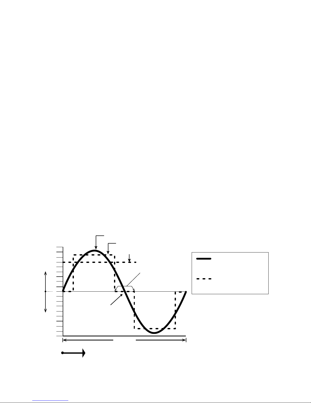
Linear Load: A load that draws sinusoidal current when a sinusoidal voltage is fed to it. Examples
are, incandescent lamp, heater, electric motor, etc.
Non-Linear Load: A load that does not draw a sinusoidal current when a sinusoidal voltage is
fed to it. For example, non-power factor corrected Switched Mode Power Supplies (SMPS) used
in computers, audio video equipment, battery chargers, etc.
Resistive Load: A device or appliance that consists of pure resistance (like lament lamps, cook
tops, toaster, coffee maker etc.) and draws only Active Power (Watts) from the inverter. The
inverter can be sized based on the Active Power rating (Watts) of the Resistive Load without
creating overload (except for resistive loads with Tungsten based heating element like lament
lamps, Quartz/Halogen lamps and Quartz / Halogen Infrared heaters. These require higher starting surge power due to lower resistance value when the heating elements are cold).
Reactive Load: A device or appliance that consists of a combination of resistive, inductive and
capacitive elements (like motor driven tools, refrigeration compressors, microwaves, computers,
audio/ video etc.). The Power Factor (PF) of this type of load is < 1 e.g. AC Motors (PF = 0.4 to
0.8), AC to DC Switch Mode Power Supplies (PF = 0.5 to 0.6), Transformers (PF = 0.8) etc. These
devices require Apparent Power (VA) from the inverter to operate. The Apparent Power is a vectorial sum of Active Power (Watts) and Reactive Power (VAR). The inverter has to be sized based on
the higher Apparent Power (VA) and also based on the Starting Surge Power.
1.3 GENERAL INFORMATION - INVERTER RELATED
General information related to operation and sizing of inverters is given in succeeding subsections.
1.3.1 AC Voltage Waveforms
TIME
180
160
140
120
100
80
60
40
20
0
20
40
60
80
100
120
140
160
180
Modied Sine
Wave sits at
ZERO for some
time and then
rises or falls
Pure Sine Wave
crosses zero V
instantaneously
Modied Sine Wave
• V
RMS
= 120V
• V
peak
= 140 to 160V
Sine Wave
• V
RMS
= 120VAC
• V
peak
= 169.68V
16.66 ms
VOLTS − VOLTS +
V
peak
= 169.68V
V
peak
= 140 to 160V
V
RMS
= 120 VAC
Fig 1.1 Pure and Modied Sine Waveforms for 120V, 60 Hz
SECTION 1 | Safety Instructions & General Information
Page 12

12 | SAMLEX AMERICA INC.
The 120V output waveform of the Evolution series inverters is a Pure Sine Wave like the waveform of Utility / Grid power. Please see Sine Waveform represented in the Fig. 1.1 that also shows
equivalent Modied Waveform for comparison.
In a Sine Wave, the voltage rises and falls smoothly with a smoothly changing phase angle and
also changes its polarity instantly when it crosses 0 Volts. In a Modied Sine Wave, the voltage
rises and falls abruptly, the phase angle also changes abruptly and it sits at 0V for some time
before changing its polarity. Thus, any device that uses a control circuitry that senses the phase
(for voltage / speed control) or instantaneous zero voltage crossing (for timing control) will not
work properly from a voltage that has a Modied Sine Waveform.
Also, as the Modied Sine Wave is a form of Square Wave, it is comprised of multiple Sine Waves
of odd harmonics (multiples) of the fundamental frequency of the Modied Sine Wave. For example, a 60 Hz Modied Sine Wave will consist of Sine Waves with odd harmonic frequencies of 3rd
(180 Hz), 5th (300 Hz), 7th (420 Hz) and so on. The high frequency harmonic content in a Modied Sine Wave produces enhanced radio interference, higher heating effect in inductive loads like
microwaves and motor driven devices like hand tools, refrigeration / air-conditioning compressors,
pumps etc. The higher frequency harmonics also produce overloading effect in low frequency
capacitors due to lowering of their capacitive reactance by the higher harmonic frequencies. These
capacitors are used in ballasts for uorescent lighting for Power Factor improvement and in singlephase induction motors as start and run capacitors. Thus, Modied and Square Wave Inverters
may shut down due to overload when powering these devices.
1.3.2 Advantages of Pure Sine Wave Inverters
The output waveform is a Sine Wave with very low harmonic distortion and cleaner power
like Grid / Utility supplied electricity.
Inductive loads like microwaves, motors, transformers etc. run faster, quieter and cooler.
More suitable for powering uorescent lighting xtures containing Power Factor Improve-
ment Capacitors and single phase motors containing Start and Run Capacitors.
Reduces audible and electrical noise in fans, uorescent lights, audio ampliers, TV, fax and
answering machines.
Does not contribute to the possibility of crashes in computers, weird print outs and glitches in
monitors.
Some examples of devices that may not work properly with Modied Sine Wave and
may also get damaged are given below:
Laser printers, photocopiers, and magneto-optical hard drives.
Built-in clocks in devices such as clock radios, alarm clocks, coffee makers, bread-makers,
VCR, microwave ovens etc. may not keep time correctly.
Output voltage control devices like dimmers, ceiling fan / motor speed control may not work
properly (dimming / speed control may not function).
Sewing machines with speed / microprocessor control.
Transformer-less capacitive input powered devices like (i) Razors, ashlights, night-lights, smoke
detectors etc. (ii) Some re-chargers for battery packs used in hand power tools. These may get
damaged. Please check with the manufacturer of these types of devices for suitability.
SECTION 1 | Safety Instructions & General Information
Page 13
Devices that use radio frequency signals carried by the AC distribution wiring.
Some new furnaces with microprocessor control / Oil burner primary controls.
High intensity discharge (HID) lamps like Metal Halide lamps. These may get damaged. Please
check with the manufacturer of these types of devices for suitability.
Some uorescent lamps / light xtures that have Power Factor Correction Capacitors. The
inverter may shut down indicating overload.
Induction Cooktops.
1.3.3 Power Rating of Inverters
i
INFO
For proper understanding of explanations given below, please refer to denitions
of Active / Reactive / Apparent / Continuous / Surge Powers, Power Factor, and
Resistive / Reactive Loads at Section 1.2 under “DEFINITIONS”
The power rating of inverters is specied as follows:
• MaximumContinuousRunningPowerRating
• StartingSurgePowerRating
Please read details of the above two types of power ratings in Section 1.2 under “DEFINITIONS”
i
INFO
The manufacturers’ specication for power rating of AC appliances and devices
indicates only the Maximum Continuous Running Power Rating. The Starting Surge
Power required by some specic types of devices as explained above has to be
determined by actual testing or by checking with the manufacturer. This may not
be possible in all cases and hence, can be guessed at best, based on some general
Rules of Thumb.
Table 1.6 provides a list of some common AC appliances / devices that require high Starting
Surge Power. An “Inverter Sizing Factor” has been recommended against each which is a
Multiplication Factor to be applied to the Maximum Continuous Running Power Rating (Active
Power Rating in Watts) of the AC appliance / device to arrive at the Maximum Continuous
Running Power Rating of the inverter (Multiply the Maximum Continuous Running Power
Rating (Active Power Rating in Watts) of the appliance / device by recommended Sizing Factor
to arrive at the Maximum Continuous Running Power Rating of the inverter.
SECTION 1 | Safety Instructions & General Information
Page 14

14 | SAMLEX AMERICA INC.
TABLE 1.6 INVERTER SIZING FACTOR
Type of Device or Appliance
Inverter Sizing Factor
(See Note 1)
Air Conditioner / Refrigerator / Freezer (Compressor based) 5
Air Compressor 4
Sump Pump / Well Pump / Submersible Pump 3
Dishwasher / Clothes Washer 3
Microwave (where rated output power is the Cooking Power) 2
Furnace Fan 3
Industrial Motor 3
Portable Kerosene / Diesel Fuel Heater 3
Circular Saw / Bench Grinder 3
Incandescent / Halogen / Quartz Lamps 3
Laser Printer / Other Devices using Infrared, Quartz Halogen Heaters 4
Switch Mode Power Supplies (SMPS): no Power Factor correction 2
Photographic Strobe / Flash Lights 4 (See Note 2)
NOTES FOR TABLE 1.6:
1 Multiply the Maximum Continuous Power Rating (Active Power Rating in Watts) of the appli-
ance / device by the recommended sizing factor to arrive at the Maximum Continuous Running
Power Rating of the Inverter.
2 For photographic strobe / ash unit, the Surge Power of the inverter should be > 4 times the
Watt Sec rating of photographic strobe / ash unit.
1.3.4 Electro-Magnetic Interference (EMI) and FCC Compliance
These inverters contain internal switching devices that generate conducted and radiated
electromagnetic interference (EMI). The EMI is unintentional and cannot be entirely eliminated.
The magnitude of EMI is, however, limited by circuit design to acceptable levels as per limits
laid down in North American FCC Standard FCC Part 15(B), Class B. These limits are designed
to provide reasonable protection against harmful interference when the equipment is operated
in a residential environment. These inverters can conduct and radiate radio frequency energy
and, if not installed and used in accordance with the instruction manual, may cause harmful
interference to radio communications. The effects of EMI will also depend upon a number of
factors external to the inverter like proximity of the inverter to the EMI receptors, types and
quality of connecting wires and cables etc. EMI due to factors external to the inverter may be
reduced as follows:
• Ensure that the inverter is rmly grounded to the Ground System of the building or the
vehicle.
• Locate the inverter as far away from the EMI receptors like radio, audio and video
devices as possible.
• Keep the DC side wires between the battery and the inverter as short as possible.
• Do NOT keep the battery wires far apart. Keep them taped together to reduce their
inductance and induced voltages. This reduces ripple in the battery wires and improves
performance and efciency.
SECTION 1 | Safety Instructions & General Information
Page 15

• Shield the DC side wires with metal sheathing / copper foil / braiding.
• Use coaxial shielded cable for all antenna inputs (instead of 300 ohm twin leads).
• Use high quality shielded cables to attach audio and video devices to one another.
• Limit operation of other high power loads when operating audio / video equipment.
1.3.5 Characteristics of Switch Mode Power Supplies (SMPS)
Switch Mode Power Supplies (SMPS) are extensively used to convert the incoming AC power into
various voltages like 3.3V, 5V, 12V, 24V etc. that are used to power various devices and circuits
used in electronic equipment like battery chargers, computers, audio and video devices, radios
etc. These power supplies use large capacitors in their input section for ltration. When the
power supply is rst turned on, there is a very large inrush current drawn by the power supply as
the input capacitors are charged (The capacitors act almost like a short circuit at the instant the
power is turned on). The inrush current at turn-on is several to tens of times larger than the rated
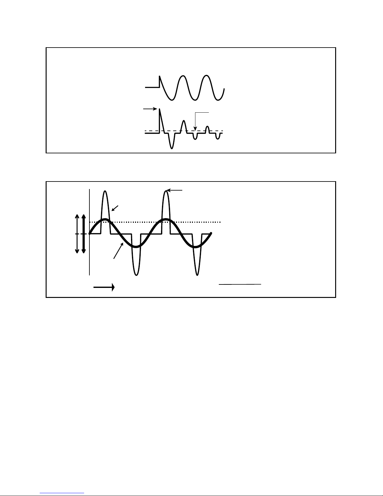
RMS input current and lasts for a few milliseconds. An example of the input voltage versus input
current waveforms is given in Fig. 1.2. It will be seen that the initial input current pulse just after
turn-on is > 15 times larger than the steady state RMS current. The inrush dissipates in around 2
or 3 cycles i.e. in around 33 to 50 milliseconds for 60 Hz sine wave.
Further, due to the presence of high value of input lter capacitors, the current drawn by an
SMPS (With no Power Factor correction) is not sinusoidal but non-linear as shown in Fig 1.3.
The steady state input current of SMPS is a train of non-linear pulses instead of a sinusoidal
wave. These pulses are two to four milliseconds duration each with a very high Crest Factor of
around 3. Crest Factor is dened by the following equation: CREST FACTOR = PEAK VALUE
÷ RMS VALUE
Many SMPS units incorporate “Inrush Current Limiting”. The most common method is the NTC
(Negative Temperature Coefcient) resistor. The NTC resistor has a high resistance when cold
and a low resistance when hot. The NTC resistor is placed in series with the input to the power
supply. The higher cold resistance limits the input current as the input capacitors charge up. The
input current heats up the NTC and the resistance drops during normal operation. However,
if the power supply is quickly turned OFF and back ON, the NTC resistor will be hot so its low
resistance state will not prevent an inrush current event.
The inverter should, therefore, be sized adequately to withstand the high inrush current and
the high Crest Factor of the current drawn by the SMPS. Normally, inverters have short duration
Surge Power Rating of 2 times their Maximum Continuous Power Rating. Hence, it is recom-
mended that for purposes of sizing the inverter, to accommodate Crest Factor of 3,
the Maximum Continuous Power Rating of the inverter should be > 2 times the Maximum Continuous Rated Power of the SMPS. For example, an SMPS rated at 100 Watts
should be powered from an inverter that has Maximum Continuous Power Rating of
> 200 Watts.
SECTION 1 | Safety Instructions & General Information
Page 16
16 | SAMLEX AMERICA INC.
Input voltage
Peak Inrush Current
Inrush current
Rated Steady State
Input RMS Current
NOTE: Voltage and
Current scales
are dierent
Fig 1.2 Inrush current in an SMPS
TIME
Peak Current
RMS Current
Non-linear
Input Current
Input Sine
Wave Voltage
CREST FACTOR = PEAK CURRENT = 3
RMS CURRENT
NOTE: Voltage and
Current scales
are dierent
Volatge − Voltage +
Current − Current +
Fig 1.3 High Crest Factor of current drawn by SMPS
1.4 GENERAL INFORMATION - LEAD ACID BATTERIES
Lead-acid batteries can be categorized by the type of application:
1. Automotive service - Starting/Lighting/Ignition (SLI, a.k.a. cranking), and
2. Deep cycle service.
Deep Cycle Lead Acid Batteries of appropriate capacity are recommended for powering of
inverters.
SECTION 1 | Safety Instructions & General Information
Page 17

1.4.1 Deep Cycle Lead Acid Batteries
Deep cycle batteries are designed with thick-plate electrodes to serve as primary power sources,
to have a constant discharge rate, to have the capability to be deeply discharged to up to 80 %
capacity and to repeatedly accept recharging. They are marketed for use in recreation vehicles
(RV), boats and electric golf carts – so they may be referred to as RV batteries, marine batteries
or golf cart batteries. Use Deep Cycle batteries for powering inverters.
1.4.2 Rated Capacity Specied in Ampere-hour (Ah)
Battery capacity “C” is specied in Ampere-hours (Ah). An Ampere is the unit of measurement
for electrical current and is dened as a Coulomb of charge passing through an electrical
conductor in one second. The Capacity “C” in Ah relates to the ability of the battery to provide
a constant specied value of discharge current (also called “C-Rate” - see page 17) over a
specied time in hours before the battery reaches a specied discharged terminal voltage (Also
called “End Point Voltage”) at a specied temperature of the electrolyte. As a benchmark, the
automotive battery industry rates batteries at a discharge current or C-Rate of C/20 Amperes
corresponding to 20 Hour discharge period. The rated capacity “C” in Ah in this case will be
the number of Amperes of current the battery can deliver for 20 Hours at 80ºF (26.7ºC) till the
voltage drops to 1.75V / Cell. i.e. 10.5V for 12V battery or 21V for 24V battery. For example, a
100 Ah battery will deliver 5A for 20 Hours.
1.4.3 Rated Capacity Specied in Reserve Capacity (RC)
Battery capacity may also be expressed as Reserve Capacity (RC) in minutes typically for
automotive SLI (Starting, Lighting and Ignition) batteries. It is the time in minutes a vehicle can
be driven after the charging system fails. This is roughly equivalent to the conditions after the
alternator fails while the vehicle is being driven at night with the headlights on. The battery
alone must supply current to the headlights and the computer/ignition system. The assumed
battery load is a constant discharge current of 25A.
Reserve capacity is the time in minutes for which the battery can deliver 25 Amperes at 80ºF
(26.7ºC) till the voltage drops to 1.75V / Cell i.e. 10.5V for 12V battery or 21V for 24V battery.
Approximate relationship between the two units is: Capacity “C” in Ah = Reserve Capacity in
RC minutes x 0.6
1.4.4 Typical Battery Sizes
Table 1.7 shows details of some popular battery sizes:
TABLE 1.7 POPULAR BATTERY SIZES
BCI* Group Battery Voltage, V Battery Capacity, Ah
27 / 31 12 105
4D 12 160
8D 12 225
GC2** 6 220
* Battery Council International; ** Golf Cart
SECTION 1 | Safety Instructions & General Information
Page 18

18 | SAMLEX AMERICA INC.
1.4.5 Specifying Charging / Discharging Currents: C-Rate
Electrical energy is stored in a cell / battery in the form of DC power. The value of the stored
energy is related to the amount of the active materials pasted on the battery plates, the surface
area of the plates and the amount of electrolyte covering the plates. As explained above, the
amount of stored electrical energy is also called the Capacity of the battery and is designated by
the symbol “C”.
The time in Hours over which the battery is discharged to the “End Point Voltage” for purposes
of specifying Ah capacity depends upon the type of application. Let us denote this discharge
time in hours by “T”. Let us denote the rate of discharge current of the battery as a multiple of
Ah capacity "C" and call it as the "C-Rate”. If the battery delivers a very high discharge current,
the battery will be discharged to the “End Point Voltage” in a shorter period of time. On the
other hand, if the battery delivers a lower discharge current, the battery will be discharged to
the “End Point Voltage” after a longer period of time. Mathematically, C-Rate is dened as:
“C-RATE” = CAPACITY “C” in Ah ÷ DISCHARGE TIME “T”
Table 1.8 gives some examples of C-Rate specications and applications:
TABLE 1.8 DISCHARGE CURRENT RATES - “C-RATES”
Hours of discharge time “T” till
the “End Point Voltage”
“C-Rate” Discharge Current
in Amps = Capacity “C” in Ah
÷ Discharge Time “T” in Hrs.
Example of C-Rate
Discharge Currents
for 100 Ah battery
0.5 Hrs. 2C 200A
1 Hrs. 1C 100A
5 Hrs.
(Inverter application) C/5 or 0.2C 20A
8 Hrs.
(UPS application) C/8 or 0.125C 12.5A
10 Hrs.
(Telecom application) C/10 or 0.1C 10A
20 Hrs. (
Automotive application) C/20 or 0.05C 5A
100 Hrs. C/100 or 0.01C 1A
NOTE: When a battery is discharged over a shorter time, its specied “C-Rate” will be higher. For example, the “C-Rate” at 5 Hour discharge period i.e. C/5 Amps will be 4 times higher than the “C-Rate” at
20 Hour discharge period i.e. C/20 Amps.
1.4.6 Charging / Discharging Curves
Fig. 1.4 shows the charging and discharging characteristics of a typical 12V / 24V Flooded
Lead Acid battery at electrolyte temperature of 80°F / 26.7°C. The curves show the % State
of Charge (X-axis) versus terminal voltage (Y-axis) during charging and discharging at different
C-Rates. Please note that X-axis shows % State of Charge. State of Discharge will be =
100% - % State of Charge. These curves will be referred to in the subsequent explanations.
SECTION 1 | Safety Instructions & General Information
Page 19
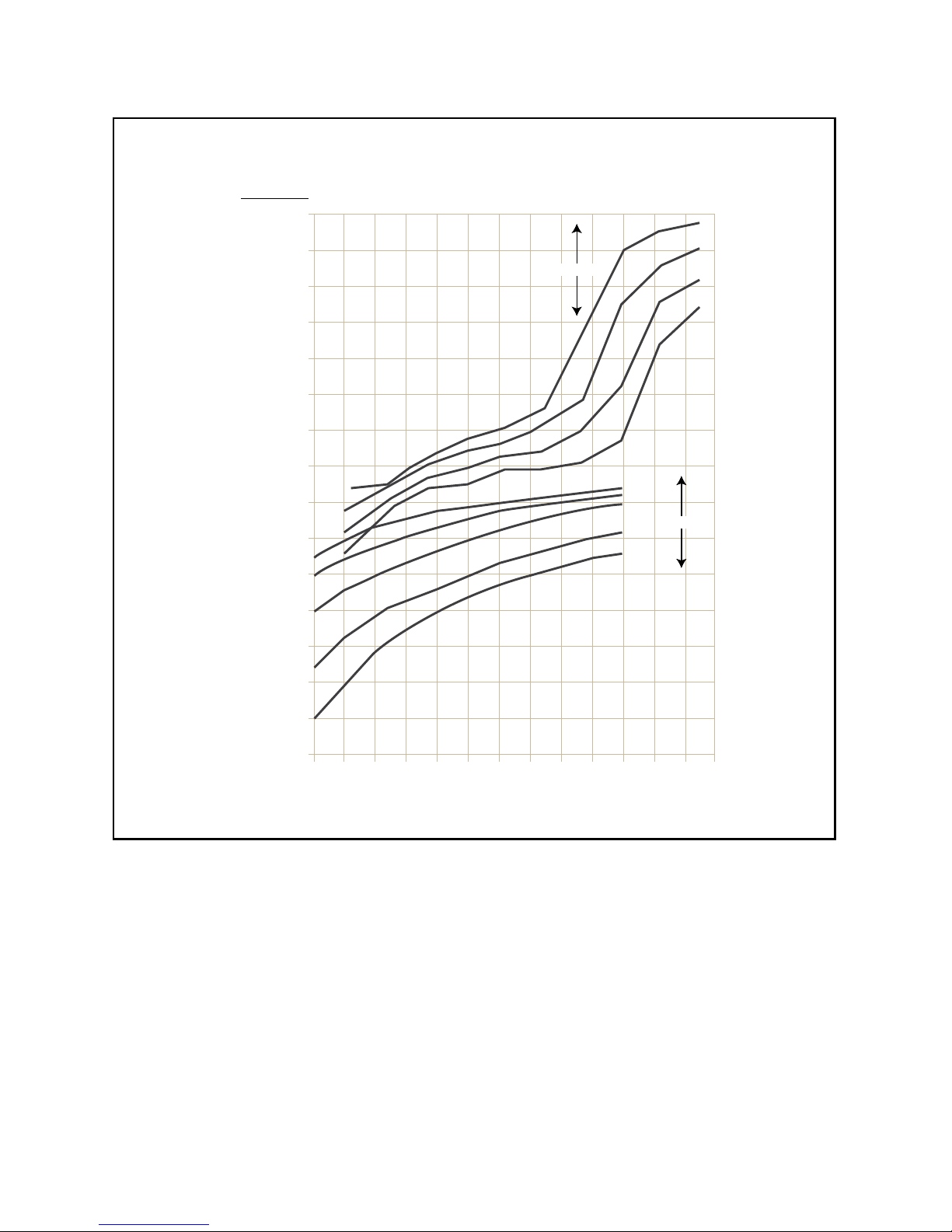
Fig 1.4 Charging / Discharging Curves for Typical Flooded Lead Acid Battery
1.4.7 Reduction in Usable Capacity at Higher Discharge Rates – Typical in
Inverter Application
As stated earlier, the Ah capacity of automotive battery is normally applicable at a discharge rate
of 20 Hours. As the discharge rate is increased as in cases where the inverters are driving higher
capacity loads, the usable Ah capacity reduces due to “Peukert Effect”. This relationship is not
linear but is more or less according to the Table 1.9.
SECTION 1 | Safety Instructions & General Information
Typical Flooded Lead-Acid Battery Chart - 80˚F / 26.7˚C
Battery Voltage in VDC
Battery State of Charge in Percent (%)
0 10 20 30 40 50 60 70 80 90 100 110 120 130
16.5
16.0
15.5
15.0
14.5
14.0
13.5
13.0
12.5
12.0
11.5
11.0
10.5
10.0
9.5
9.0
C/5
C/40
C/20
C/10
DISCHARGE
CHARGE
C/20
C/3
C/5
C/10
C/100
33.0
32.0
31.0
30.0
29.0
28.0
27.0
26.0
25.0
24.0
23.0
22.0
21.0
20.0
19.0
18.0
24V 12V
Page 20
20 | SAMLEX AMERICA INC.
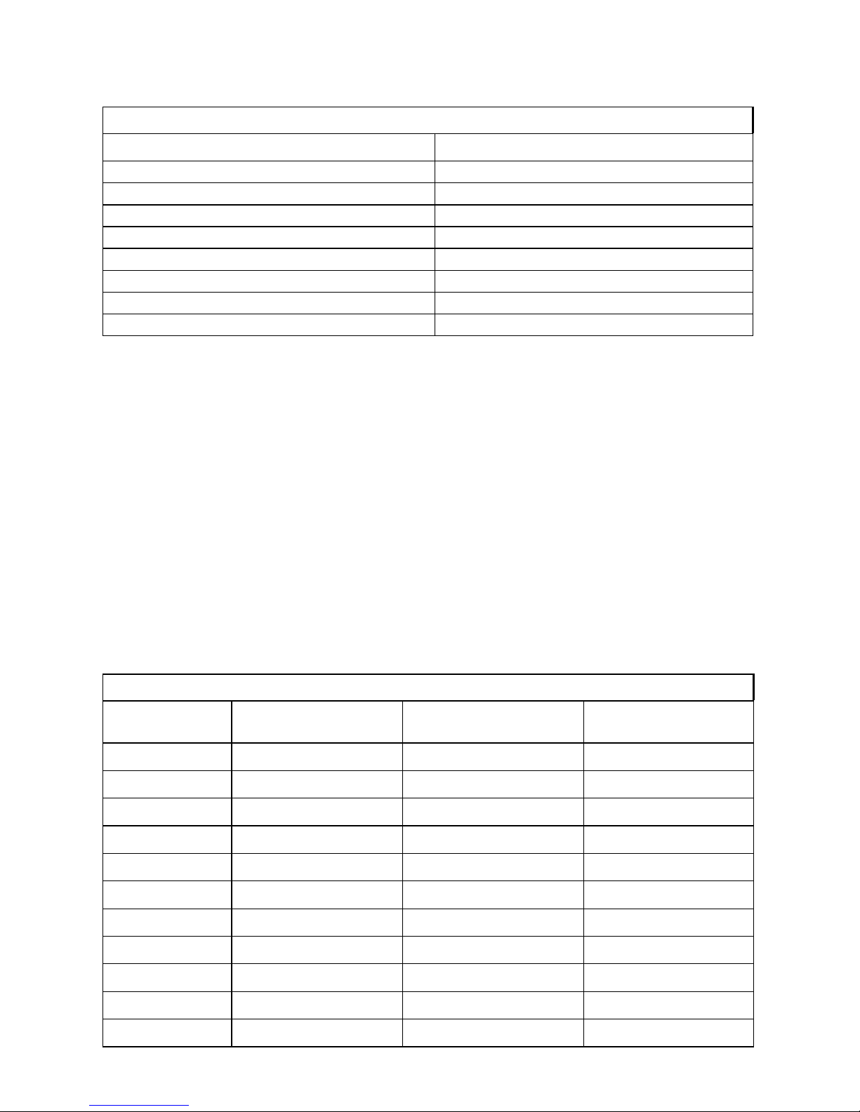
TABLE 1.9 BATTERY CAPACITY VERSUS RATE OF DISCHARGE – C-RATE
C-Rate Discharge Current Usable Capacity (%)
C/20 100%
C/10 87%
C/8 83%
C/6 75%
C/5 70%
C/3 60%
C/2 50%
1C 40%
Table 1.9 shows that a 100 Ah capacity battery will deliver 100% (i.e. full 100 Ah) capacity if it
is slowly discharged over 20 Hours at the rate of 5 Amperes (50W output for a 12V inverter and
100W output for a 24V inverter). However, if it is discharged at a rate of 50 Amperes (500W
output for a 12V inverter and 1000W output for a 24V inverter) then theoretically, it should
provide 100 Ah ÷ 50 = 2 Hours. However, Table 1.9 above shows that for 2 Hours discharge
rate, the capacity is reduced to 50% i.e. 50 Ah. Therefore, at 50 Ampere discharge rate (500W
output for a 12V inverter and 1000W output for a 24V inverter) the battery will actually last for
50 Ah ÷ 50 Amperes = 1 Hour.
1.4.8 State of Charge (SOC) of a Battery – Based on “Standing Voltage”
The “Standing Voltage” of a battery under open circuit conditions (no load connected to it)
can approximately indicate the State of Charge (SOC) of the battery. The “Standing Voltage”
is measured after disconnecting any charging device(s) and the battery load(s) and
letting the battery “stand” idle for 3 to 8 hours before the voltage measurement is
taken. Table 1.10 shows the State of Charge versus Standing Voltage for a typical 12V/24V
battery system at 80°F (26.7ºC).
TABLE 1.10 SOC VERSUS STANDING VOLTAGE (TYPICAL FLOODED BATTERY)
Percentage of
Full Charge
Standing Voltage
of Individual Cells
Standing Voltage of
12V Battery
Standing Voltage
of 24V Battery
100% 2.105V 12.63V 25.26V
90% 2.10V 12.6V 25.20V
80% 2.08V 12.5V 25.00V
70% 2.05V 12.3V 24.60V
60% 2.03V 12.2V 24.40V
50% 2.02V 12.1V 24.20V
40% 2.00V 12.0V 24.00V
30% 1.97V 11.8V 23.60V
20% 1.95V 11.7V 23.40V
10% 1.93V 11.6V 23.20V
0% = / < 1.93V = / < 11.6V = / < 23.20V
SECTION 1 | Safety Instructions & General Information
Page 21

Check the individual cell voltages / specic gravity. If the inter-cell voltage difference is more
than a 0.2V, or the specic gravity difference is 0.015 or more, the cells will require equalization.
Please note that only non-sealed / vented / ooded / wet cell batteries are equalized.
Do not equalize sealed / VRLA type of AGM or Gel Cell Batteries.
1.4.9 State of Discharge of a Loaded Battery – Low Battery / DC Input Voltage
Alarm and Shutdown in Inverters
Most inverter hardware estimate the State of Discharge of the loaded battery by measuring
the voltage at the inverter’s DC input terminals (considering that the DC input cables are thick
enough to allow a negligible voltage drop between the battery and the inverter).
Inverters are provided with a buzzer alarm to warn that the loaded battery has been deeply
discharged to around 80% of the rated capacity. Normally, the buzzer alarm is triggered
when the voltage at the DC input terminals of the inverter has dropped to around
10.5V for a 12V battery or 21V for 24V battery at C-Rate discharge current of C/5
Amps and electrolyte temp. of 80°F. The inverter is shut down if the terminal voltage at C/5
discharge current falls further to 10V for 12V battery or 20V for 24V battery.
The State of Discharge of a battery is estimated based on the measured terminal voltage of the
battery. The terminal voltage of the battery is dependent upon the following:
- Temperature of the battery electrolyte: Temperature of the electrolyte affects the
electrochemical reactions inside the battery and produces a Negative Voltage Coefcient –
during charging / discharging, the terminal voltage drops with rise in temperature and rises
with drop in temperature
- The amount of discharging current or “C-Rate”: A battery has non linear internal
resistance and hence, as the discharge current increases, the battery terminal voltage
decreases non-linearly
The discharge curves in Fig. 1.4 show the % State of Charge versus the terminal voltage of
typical Flooded Lead Acid Battery under different charge /discharge currents, i.e. “C-Rates”
and xed temperature of 80°F. (Please note that the X-Axis of the curves shows the % of
State of Charge. The % of State of Discharge will be 100% - % State of Charge).
1.4.10 Low DC Input Voltage Alarm in Inverters
As stated earlier, the buzzer alarm is triggered when the voltage at the DC input terminals of
the inverter has dropped to around 10.5V for a 12V battery or 21V for 24V battery at C-Rate
discharge current of C/5 Amps. Please note that the terminal voltage relative to a particular
State of Discharge decreases with the rise in the value of the discharge current. For example,
terminal voltages for a State of Discharge of 80% (State of Charge of 20%) for various
discharge currents will be as given at Table 1.11 (Refer to Fig. 1.4 for parameters and values
shown in Table 1.11):
SECTION 1 | Safety Instructions & General Information
Page 22
22 | SAMLEX AMERICA INC.
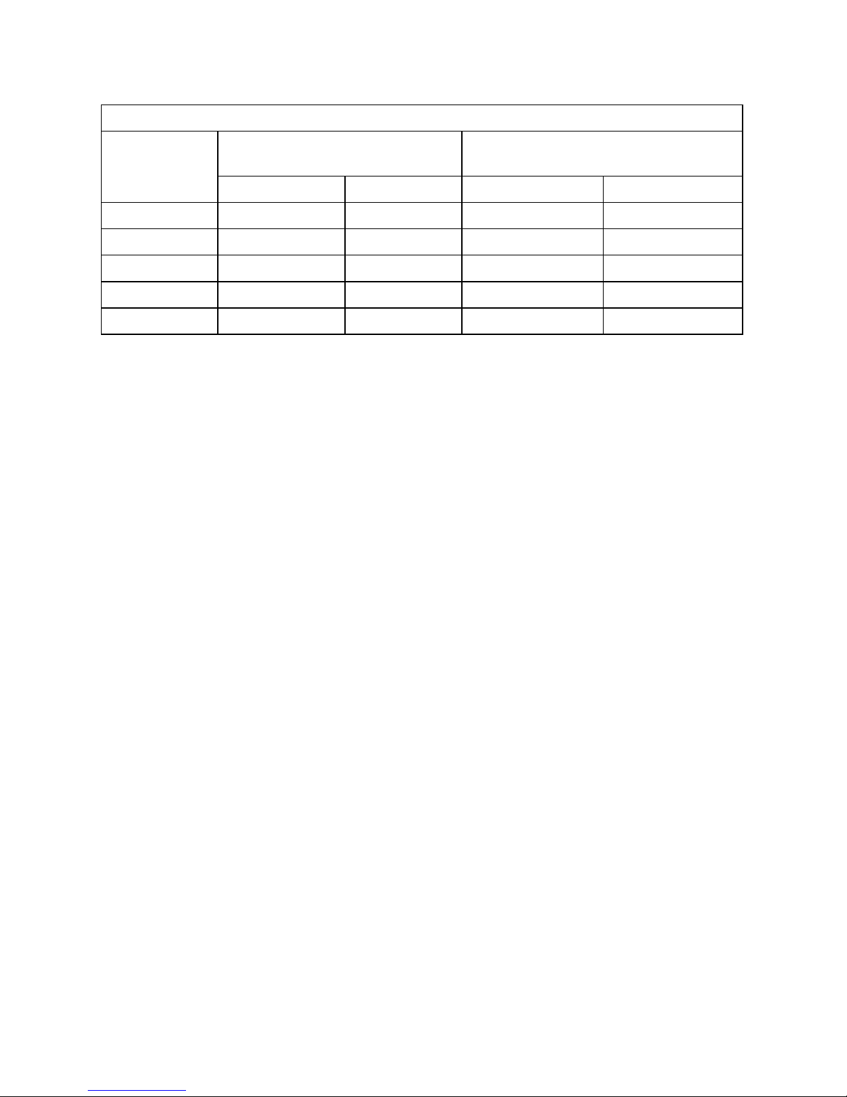
Table 1.11 TERMINAL VOLTAGE AND SOC OF LOADED BATTERY
Discharge
Current:
C-Rate
Terminal Voltage at 80% State
of Discharge (20% SOC)
Terminal Voltage When Completely
Discharged (0% SOC)
12V 24V 12V 24V
C/3 A 10.45V 20.9V 09.50V 19.0V
C/5 A 10.90V 21.8V 10.30V 20.6V
C/10 A 11.95V 23.9V 11.00V 22.0V
C/20 A 11.85V 23.7V 11.50V 23.0V
C/100 A 12.15V 24.3V 11.75V 23.5V
In the example given above, the 10.5V / 21.0V Low Battery / DC Input Alarm would trigger
at around 80% discharged state (20% SOC) when the C-Rate discharge current is C/5 Amps.
However, for lower C-Rate discharge current of C/10 Amps and lower, the battery will be almost
completely discharged when the alarm is sounded. Hence, if the C-Rate discharge current
is lower than C/5 Amps, the battery may have completely discharged by the time the
Low DC Input Alarm is sounded.
1.4.11 Low DC Input Voltage Shut-down In Inverters
As explained above, at around 80% State of Discharge of the battery at C-Rate discharge
current of around C/5 Amps, the Low DC Input Voltage Alarm is sounded at around 10.5V for
a 12V battery (at around 21V for 24V battery) to warn the user to disconnect the battery to
prevent further draining of the battery. If the load is not disconnected at this stage, the batteries
will be drained further to a lower voltage and to a completely discharged condition that is
harmful for the battery and for the inverter.
Inverters are normally provided with a protection to shut down the output of the inverter if the
DC voltage at the input terminals of the inverter drops below a threshold of around 10V for a
12V battery (20V for 24V battery). Referring to the Discharge Curves given in Fig 1.4, the State
of Discharge for various C-Rate discharge currents for battery voltage of 10V / 20V is as follows:
(Please note that the X-Axis of the curves shows the % of State of Charge. The % of State of
Discharge will be 100% - % State of Charge):
-
85% State of Discharge (15% State of Charge) at very high C-rate discharge current of C/3 Amps.
- 100% State of Discharge (0 % State of Charge) at high C-Rate discharge current of C/5 Amps.
- 100% discharged (0% State of charge) at lower C-rate Discharge current of C/10 Amps.
It is seen that at DC input voltage of 10V / 20V, the battery is completely discharged for C-rate
discharge current of C/5 and lower
.
In view of the above, it may be seen that a xed Low DC Input Voltage Alarm is not
useful. Temperature of the battery further complicates the situation. All the above analysis is
based on battery electrolyte temperature of 80°F. The battery capacity varies with temperature.
Battery capacity is also a function of age and charging history. Older batteries have lower
capacity because of shedding of active materials, sulfation, corrosion, increasing number of
charge / discharge cycles etc. Hence, the State of Discharge of a battery under load cannot be
estimated accurately. However, the low DC input voltage alarm and shut-down functions are
designed to protect the inverter from excessive current drawn at the lower voltage.
SECTION 1 | Safety Instructions & General Information
Page 23
1.4.12 Depth of Discharge of Battery and Battery Life
The more deeply a battery is discharged on each cycle, the shorter the battery life. Using more
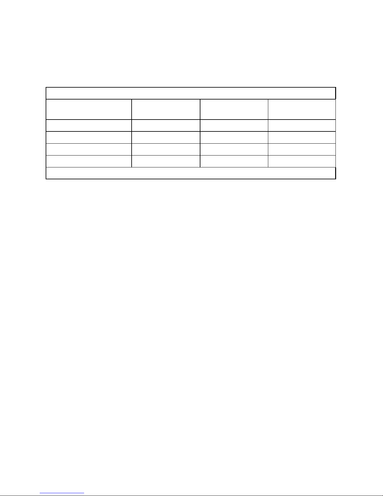
batteries than the minimum required will result in longer life for the battery bank. A typical cycle
life chart is given in the Table 1.12 below:
TABLE 1.12 TYPICAL CYCLE LIFE CHART
Depth of Discharge
% of Ah Capacity
Cycle Life of
Group 27 /31
Cycle Life of
Group 8D
Cycle Life of
Group GC2
10 1000 1500 3800
50 320 480 1100
80 200 300 675
100 150 225 550
NOTE: It is recommended that the depth of discharge should be limited to 50%.
1.4.13 Series and Parallel Connection of Batteries
Refer to details at Section 3.4.
1.4.14 Sizing the Inverter Battery Bank
One of the most frequently asked questions is, “how long will the batteries last?” This question
cannot be answered without knowing the size of the battery system and the load on the
inverter. Usually this question is turned around to ask “How long do you want your load to
run?”, and then specic calculation can be done to determine the proper battery bank size.
There are a few basic formulae and estimation rules that are used:
1. Active Power in Watts (W) = Voltage in Volts (V) x Current in Amperes (A) x Power Factor
2. For an inverter running from a 12V battery system, the approximate DC current required
from the 12V batteries is the AC power delivered by the inverter to the load in Watts (W)
divided by 10 & for an inverter running from a 24V battery system, the approximate DC
current required from the 24V batteries is the AC power delivered by the inverter to the
load in Watts (W) divided by 20.
3. Energy required from the battery = DC current to be delivered (A) x Time in Hours (H).
The rst step is to estimate the total AC watts (W) of load(s) and for how long the load(s) will
operate in hours (H). The AC watts are normally indicated in the electrical nameplate for each
appliance or equipment. In case AC watts (W) are not indicated, Formula 1 given above may be
used to calculate the AC watts. The next step is to estimate the DC current in Amperes (A) from
the AC watts as per Formula 2 above. An example of this calculation for a 12V inverter is given
below:
Let us say that the total AC Watts delivered by the inverter = 1000W.
Then, using Formula 2 above, the approximate DC current to be delivered by the 12V batteries
= 1000W ÷10 = 100 Amperes, or by 24V batteries = 1000W ÷ 20 = 50A.
Next, the energy required by the load in Ampere Hours (Ah) is determined.
For example, if the load is to operate for 3 hours then as per Formula 3 above, the energy to be
delivered by the 12V batteries = 100 Amperes × 3 Hours = 300 Ampere Hours (Ah), or by the
24V batteries = 50A x 3 Hrs = 150 Ah.
SECTION 1 | Safety Instructions & General Information
Page 24

24 | SAMLEX AMERICA INC.
Now, the capacity of the batteries is determined based on the run time and the usable
capacity.
From Table 1.9 “Battery Capacity versus Rate of Discharge”, the usable capacity at 3 Hour
discharge rate is 60%. Hence, the actual capacity of the 12V batteries to deliver 300 Ah will be
equal to: 300 Ah ÷ 0.6 = 500 Ah, and the actual capacity of the 24V battery to deliver 150 Ah
will be equal to 150 Ah ÷ 0.6 = 250 Ah.
And nally, the actual desired rated capacity of the batteries is determined based
on the fact that normally only 80% of the capacity will be available with respect to the rated
capacity due to non availability of ideal and optimum operating and charging conditions. So the
nal requirements will be equal to:
FOR 12V BATTERY: 500 Ah ÷ 0.8 = 625 Ah (note that the actual energy required by the load
was 300 Ah).
FOR 24V BATTERY: 250 Ah ÷ 0.8 = 312.5 Ah (Note that the actual energy required was 150
Ah).
It will be seen from the above that the nal rated capacity of the batteries is almost 2 times
the energy required by the load in Ah. Thus, as a Rule of Thumb, the Ah capacity of the
batteries should be twice the energy required by the load in Ah.
1.14.15 Charging Batteries
Batteries can be charged by using good quality AC powered battery charger or from alternative
energy sources like solar panels, wind or hydro systems. Make sure an appropriate Battery
Charge Controller is used. It is recommended that batteries may be charged at 10% to 20%
of their Ah capacity (Ah capacity based on 20 Hr Discharge Rate). Also, for complete charging
(return of 100% capacity), it is recommended that 4-Stage Charger may be used as follows:
Normal Charging (3-Stages)
Stage 1 (Bulk Stage at constant current) " Stage 2 (Absorption Stage at constant
voltage) " Stage 3 (Float Stage at constant voltage)
Equalization Charging (4-Stages)
Stage 1 (Bulk Stage at constant current) " Stage 2 (Absorption Stage at constant
voltage) " Stage 3 (Equalization Stage at constant voltage) " Stage 4 (Float Stage at
constant voltage)
Please refer to Section 5 for details of charging algorithm used in the Battery Charger Section of
EVO Series Inverter/Charger.
SECTION 1 | Safety Instructions & General Information
Page 25
SECTION 2 | Components & Layout
12 13
11
1
3 4
Protection Covers for Battery Terminals
8
5
2
1a Red
1b Black
9A
14
15
16
9B
9C69D
7
10A
10B
10C
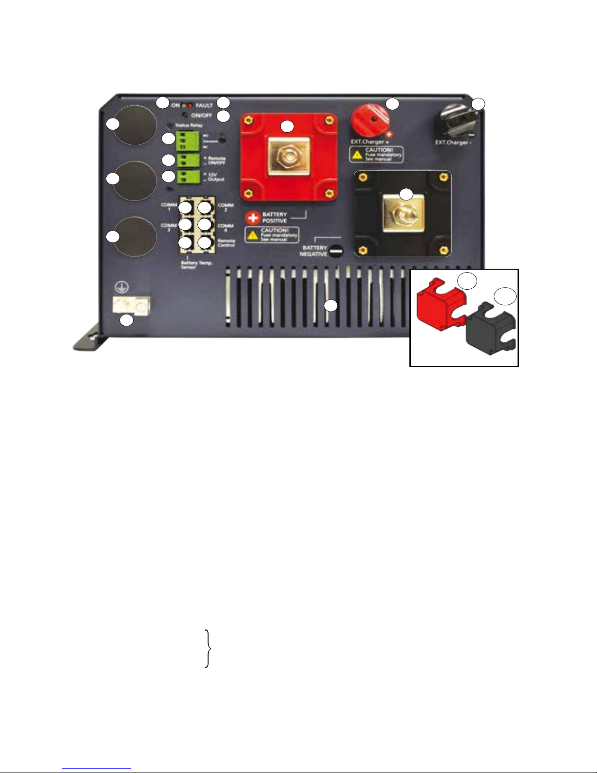
1. Battery Positive (+) Input Connector – M10 x 1.25 Nut & Bolt (RED Protection Cover 1(a) is Removed)
1a. RED Protection Cover For Battery Positive (+) Input Connector
2. Battery Negative (-) Input Connector – M10 x 1.25 Nut & Bolt (Black Protection Cover 1(b) is Removed)
2a. Black Protection Cover for Battery Negative (-) Input Connector
3. External Charger (+) Input Connector – M12 x 0.75 Thumb Nut and Bolt
4. External Charger (-) Input Connector - M12 x 0.75 Thumb Nut and Bolt
5. DC Side Grounding Connector – Hole Dia 6.5mm for wire sizes up to 25mm2 (AWG #4). Set Screw
M-8. This is internally connected to the metal chassis of the unit.
6. RJ-45 Jack for Temperature Sensor “EVO-BCTS” (Fig. 2.5)
7. RJ-45 Jack for EVO-RC Remote
8. Air inlet vents for 2 internal cooling fans [Additional air inlet vents at the bottom (not shown)]
9A, 9B. RJ-45 Jacks for Communication Ports “COMM 1” and “COMM 2” - For RS-485 networking and
MODBUS Serial Communication Protocol (for future use)
9C, 9D. RJ-45 Jacks for Communication Ports “COM 3” and “COM 4” - For “CANbus” Serial
Communication Protocol (for future use)
10A to 10C. Knock outs for AC wiring inlet/exit wiring entry (Diameter: 27.8mm / 1 3/32”) (For ¾” conduit/ttings)
11. ON/OFF Push Button
12. Green LED “ON”
13. Red LED “Fault”
14. Output Terminals for Status Relay - Screw M 2.5; Wire size: up to 4mm2 / AWG #12
• NO(NormallyOpen)
• Common
• NC(NormallyClosed)
15. +12V Input Terminals for “Remote On Off” (9 to 15V, 3mA) - Screw M 2.5; AWG #30 to #12
16. Output Terminals for +12VDC source (up to 100mA) (available only when the unit is ON) - Screw
M 2.5; Wire size: up to 4mm
2
/ AWG#12
Fig 2.1 Layout-Front
2.1 MAIN UNIT: LAYOUT-FRONT (FIG 2.1)
(i) When the Relay is OFF, "NO" and "Common" contacts are open and
"NC" and "Common" contacts are closed.
(ii) When the Relay is ON, "NO" and "Common" contacts are closed and
"NC" and "Common" contacts are open.
Page 26
26 | SAMLEX AMERICA INC.
SECTION 2 | Components & Layout
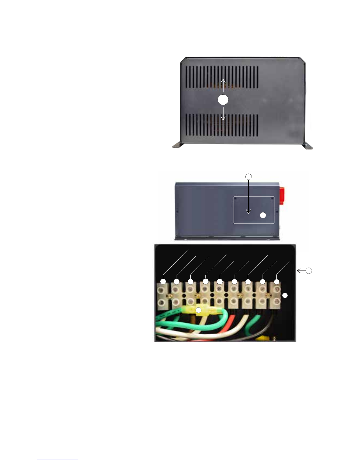
2.3 MAIN UNIT: LAYOUT-AC SIDE (FIG 2.3)
1. Cover plate for pocket for AC Input/Output terminals
2. Pocket for AC Input/Output Terminals (behind cover plate 1)
3. AC Input/Output Terminal Block
Terminal hole diameter: 6mm
for up to AWG #6
Set Screw: M4
4. Grid Input - Line
5. Grid Input - Ground
6. Grid Input - Neutral
7. Generator Input - Line
8. Generator Input - Ground
9. Generator Input - Neutral
10. AC Output - Line
11. AC Output - Ground
12. AC Output - Neutral
13. Male/Female Insulated Quick
Disconnect for disabling Output
Neutral to Chassis Ground bond
in Inverter Mode (Please see
Sections 4.5.1 to 4.5.3 and Fig 3.12)
Fig 2.2 Layout-Back
1
1
13
3
2
[Behind Cover Plate ]
2
9
10
11
4
8
7
6
5
12
OUTPUT NEUTRAL
OUTPUT GND
OUTPUT LINE
GEN NEUTRAL
GEN GND
GEN LINE
GRID NEUTRAL
GRID GND
GRID LINE
2.2 MAIN UNIT: LAYOUT-BACK (FIG 2.2)
1. Air outlet vents for 2 internal fans
Fig 2.3 Layout-AC Side
Page 27
SECTION 2 | Components & Layout
1
2
7
8
6
3
5
9
4
Fault
RJ-45
Plug
11
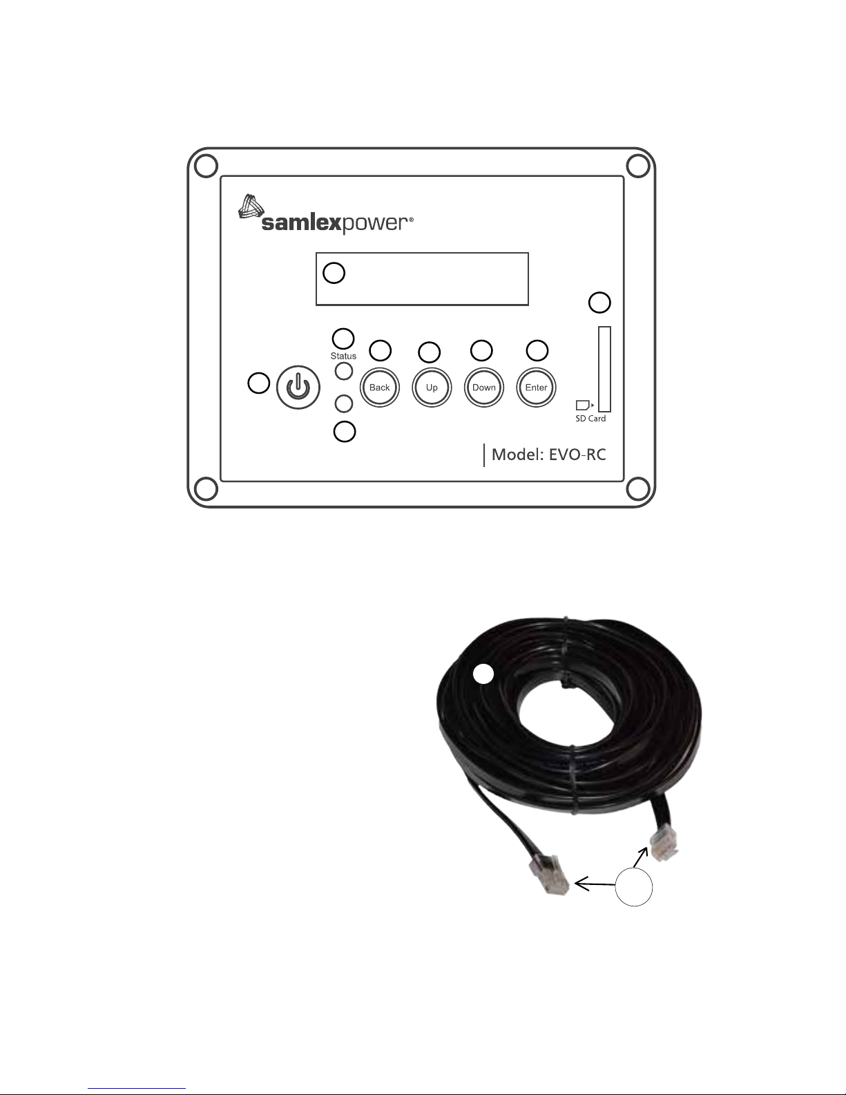
1. LCD Screen - 2 rows of 16 characters each
2. ON/OFF Key
3. Green LED “Status”
4. Red LED “Fault"
5. Navigation Key “Back”
6. Navigation Key “Up”
7. Navigation Key “Down”
8. Navigation Key “Enter”
9. SD Card Slot - FAT16/32 format; Up to 16GB
10. RJ-45 Jack (At the back-not shown)
11. RJ-45 Data Cable (Straight Wired), 10 meter/33
feet length {Fig 2.4(b)}
2.4 REMOTE CONTROL EVO-RC (FIG 2.4) [OPTIONAL]
Fig 2.4(a) Optional Remote Control EVO-RC
Fig 2.4(b) Cable for Remote Control
Page 28
28 | SAMLEX AMERICA INC.
SECTION 2 | Components & Layout
2.6 CONTENTS OF PACKAGE
Inverter/Charger
Temperature Sensor EVO-BCTS [Fig 2.5(a)]
DC Terminal Covers (1a, 1b: Fig 2.1) (Fitted on the unit with 2 screws each)
Mating Connectors (14, 15, 16: Fig 2.1)
Wire End Terminals for AC Wiring (Fig 3.11)
Model AWG#10 AWG #8 AWG#6
EVO-2212 and EVO-2224 3 6 -
EVO-3012 and EVO-4024 - 9 6
Owner's Manual
Quick Start Guide
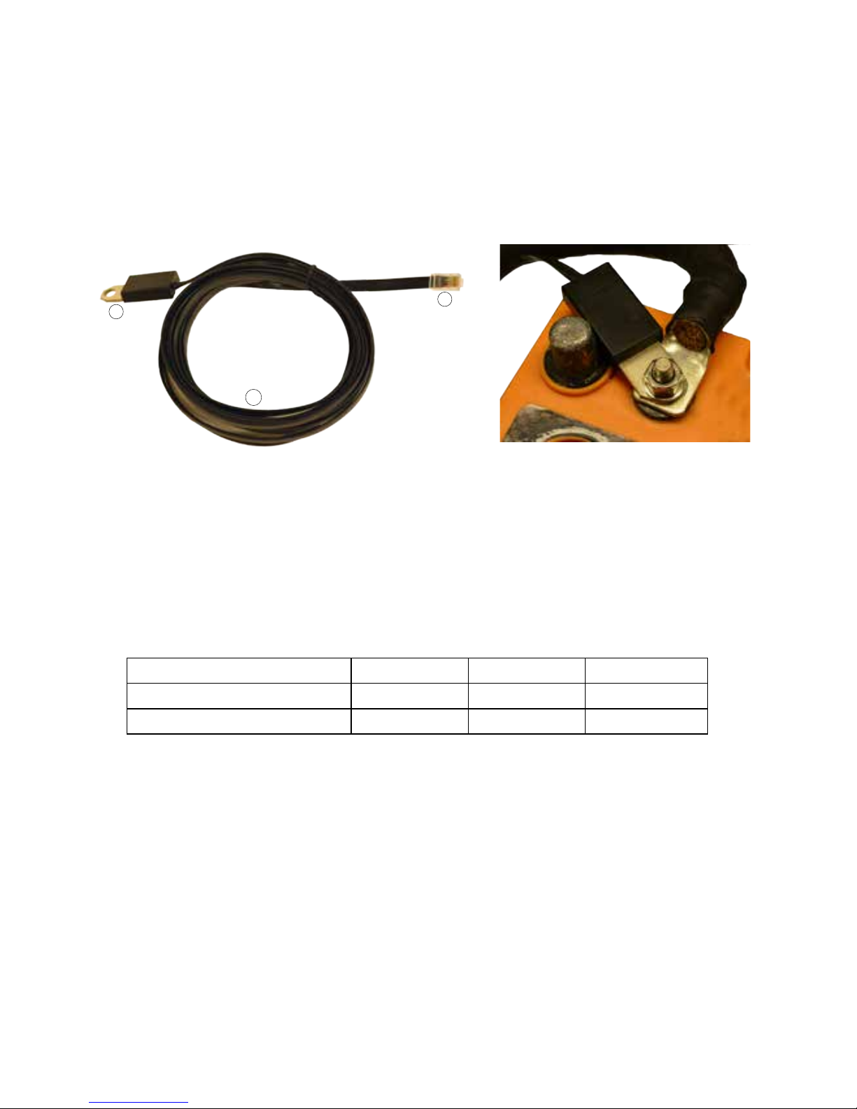
2.5 BATTERY TEMPERATURE SENSOR EVO-BCTS [FIG 2.5 (a)]
Fig 2.5(a) Temperature Sensor Model EVO-BCTS Fig 2.5(b) Temperature Sensor Installation
1. Temperature Sensor: Mounting hole: 10mm/0.39” suitable for 3/8” or 5/16” battery studs
2. RJ-45 Plug
3. 5 meter/16.5 ft cable
Note: Mount the sensor on the Positive or Negative terminal stud on the battery as shown in Fig 2.5(b)
3
1
2
Page 29
3.1 SAFETY OF INSTALLATION
WARNING!
Please ensure safety instructions given under Section 1 are strictly followed.
ATTENTION!
Se il vous plaît assurer consignes de sécurité fournies à la section 1 sont strictement suivies.
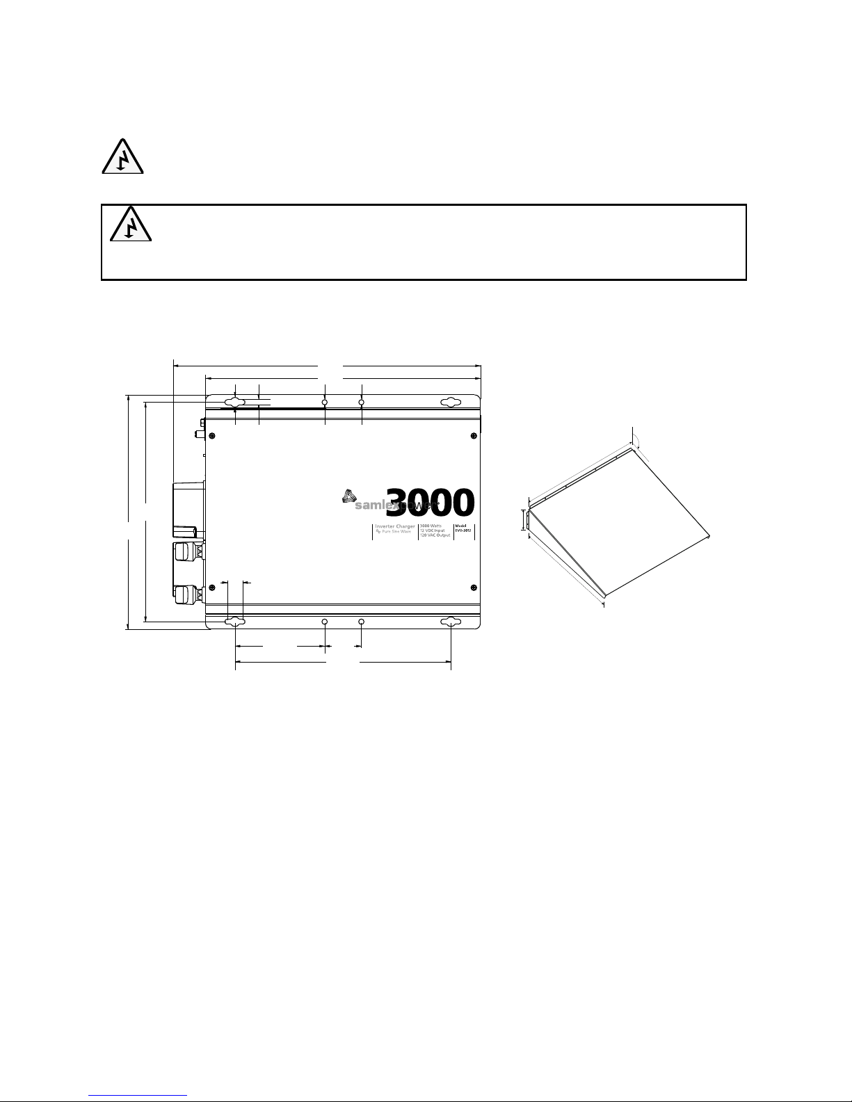
3.2 OVERALL DIMENSIONS
The overall dimensions and the location of the mounting holes are shown in Fig. 3.1.
3.3 MOUNTING OF THE UNIT
In order to meet the regulatory safety requirements, the mounting has to satisfy the following
requirements:
• Mountonanon-combustiblematerial
• Themountingsurfaceshouldbeabletosupportaweightofatleast60Kg/132lbs.
Use 4 pcs of 1/4" or M6 mounting bolts and lock washers
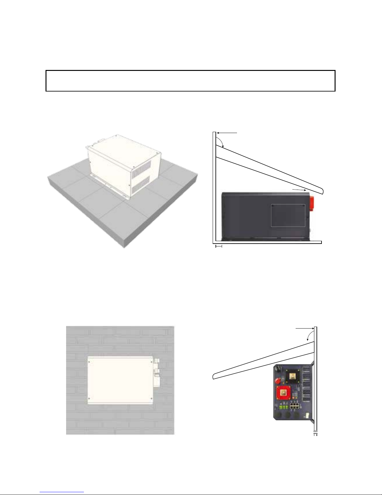
• InstallationonmarinecraftandvesselswillrequireuseofDripShieldontopoftheunitto
protect against ingress of water dripping from top. Drawing of Drip Shield is given at Fig
3.1(a). Congurations using the Drip Shield are shown under "Mounting Orientation".
Cooling: The unit has openings on the front, bottom and back for cooling and ventilation.
Ensure that these openings are not blocked or restricted. Install in cool, dry and well ventilated
area.
SECTION 3 | Installation
426
380
298,6
50,8
20,9
123,9
303,5
Height: 207.2
Dimensions in mm
325
13 7
Mounting Holes: 7mm/0.28”
Mounting Bolts: 1/4” or M6
7 7
Fig. 3.1 Mounting Dimensions
880 mm
720 mm
90 mm
Slope of top surface
should be minimum 115˚
115˚
Fig. 3.1(a) Dimensions of Drip Shield
Page 30
30 | SAMLEX AMERICA INC.
Mounting Orientation:
• Mounthorizontallyonahorizontalsurface(e.g.tabletoporashelf).PleaseseeFig.3.2.
Fig 3.2 Mounting Arrangement: Horizontally On Horizontal Surface
• Mounthorizontallyonaverticalsurface(likeawall)withthefanaxishorizontalandthe
DC input terminals facing left. Please see Fig. 3.3.
Fig 3.3 Mounting Arrangement 1: On Vertical Surface
CAUTION! Ensure there is OVER 200 mm clear space surrounding the inverter for
ventilation.
ATTENTION! Assurer qu’il y a PLUS QUE 200 mm d’espace DÉGAGÉ entourant l’onduleur pour faciliter la
ventilation.
SECTION 3 | Installation
(a) Non Marine Installation (b) Marine Installation
10 mm Gap
Top surface of
Drip Shield
55 mm
115°
Wall
Top surface of
Drip Shield
105°
Wall
(a) Non Marine Installation (b) Marine Installation
Page 31
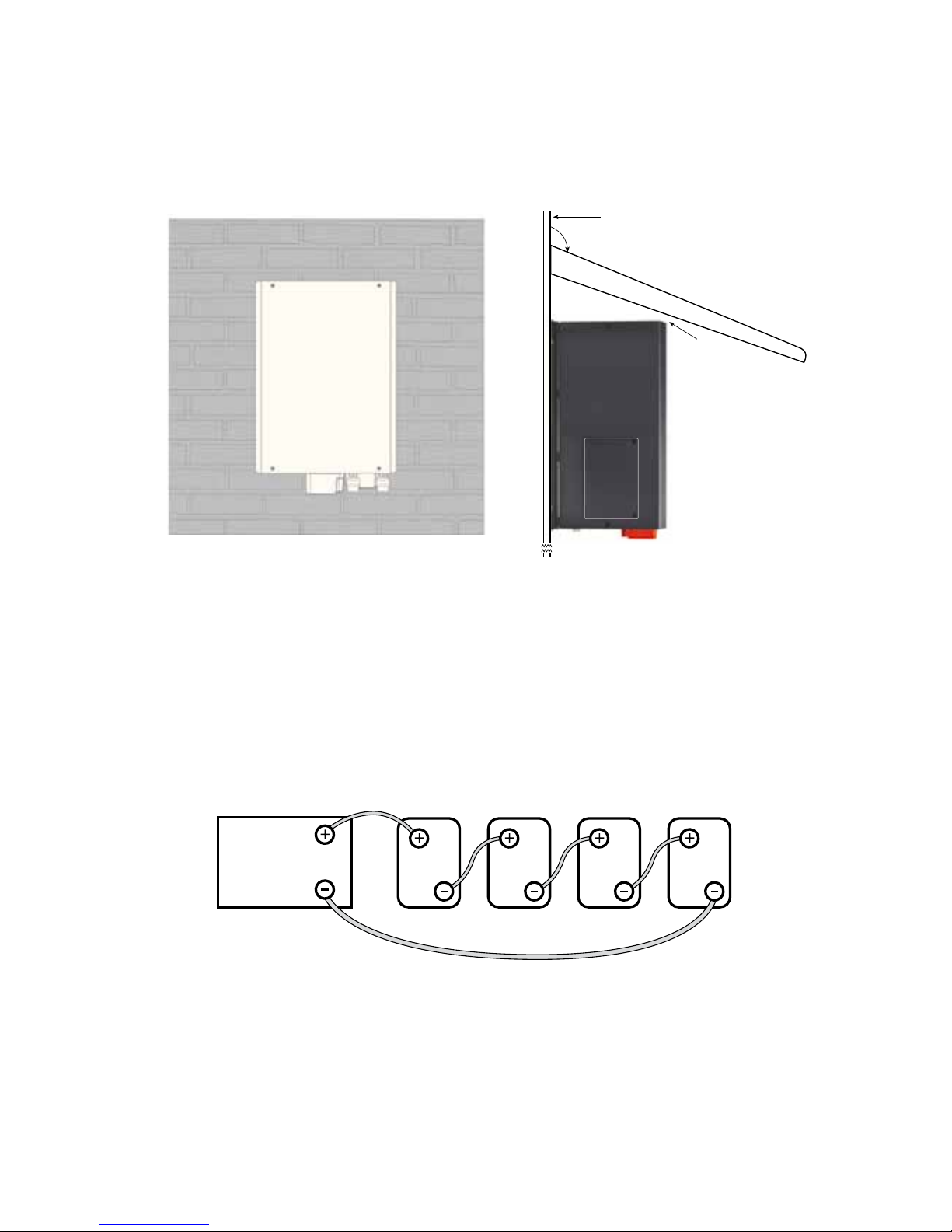
• Mountverticallyonaverticalsurface,seeFig.3.4.Protectagainstpossibilityofsmall
objects or water entering the ventilation openings on the top. (If necessary, install a
suitable sloping guard at least 200mm from the top surface). Also, ensure there is no
combustible material directly under the unit.
Fig 3.4 Mounting Arrangement 2: On Vertical Surface
3.4 INSTALLING BATTERIES - SERIES AND PARALLEL CONNECTION
Batteries are normally available in voltages of 2V, 6V and 12V and with different Ah capacities.
A number of individual batteries can be connected in series and in parallel to form a bank of
batteries with the desired increased voltage and capacity.
3.4.1 Series Connection
Fig 3.5 Series Connection
When two or more batteries are connected in series, their voltages add up but their Ah capacity
remains the same. Fig. 3.5 shows 4 pieces of 6V, 200 Ah batteries connected in series to form a
battery bank of 24V with a capacity of 200 Ah. The Positive terminal of battery 4 becomes the
Positive terminal of the 24V bank. The Negative terminal of battery 4 is connected to the Positive
terminal of battery 3. The Negative terminal of battery 3 is connected to the Positive terminal of
battery 2. The Negative terminal of battery 2 is connected to the Positive terminal of battery 1.
The Negative terminal of battery 1 becomes the Negative terminal of the 24V battery bank.
SECTION 3 | Installation
6V 6V
Battery 4 Battery 3
6V
Battery 2
6V
Battery 1
24V Inverter
or 24V Charger
Cable “A”
Cable “B”
10 mm Gap
Top surface of
Drip Shield
115°
Wall
(a) Non Marine Installation (b) Marine Installation
Page 32
32 | SAMLEX AMERICA INC.
3.4.2 Parallel Connection
Fig 3.6 Parallel Connection
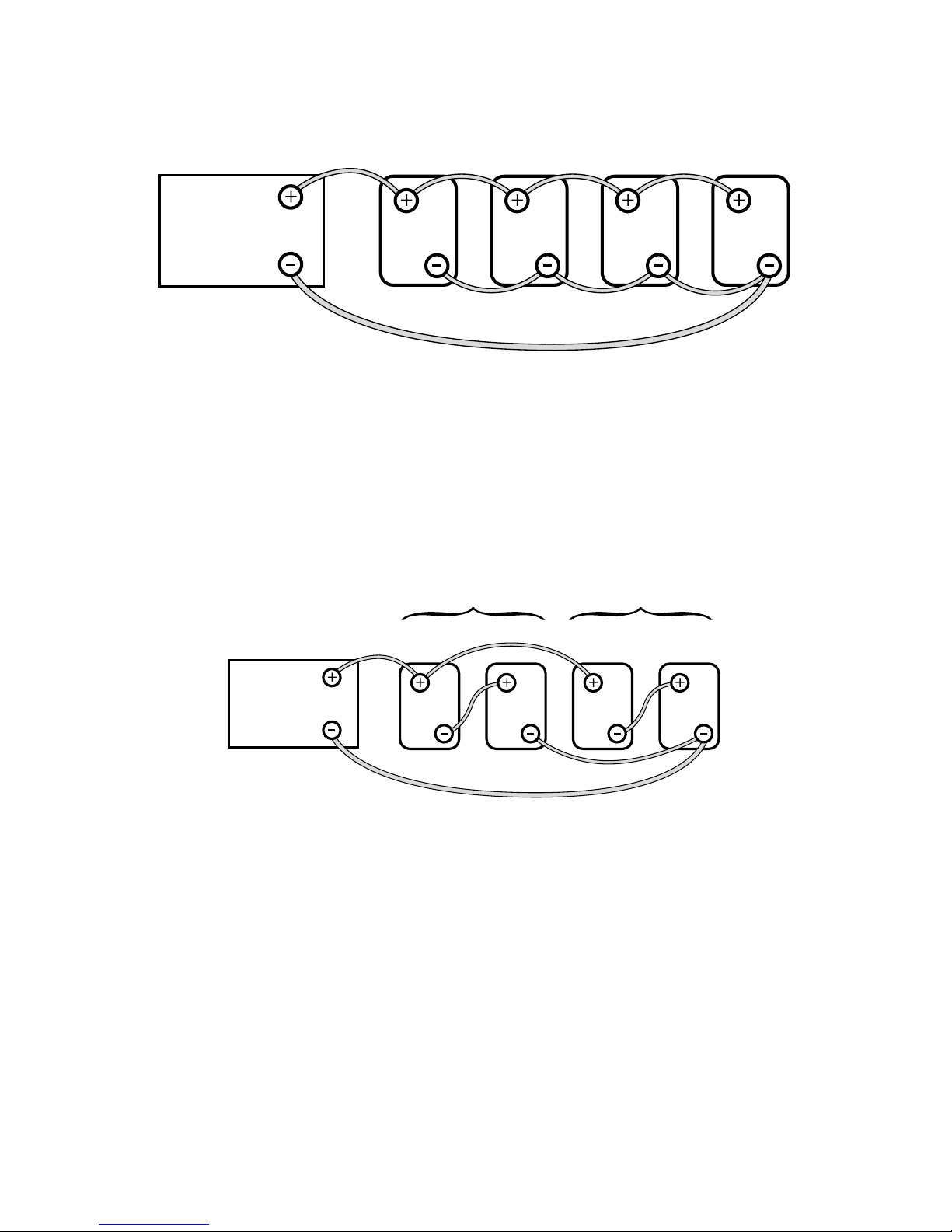
When two or more batteries are connected in parallel, their voltage remains the same but their
Ah capacities add up. Fig. 3.6 above shows 4 pieces of 12V, 100 Ah batteries connected in
parallel to form a battery bank of 12V with a capacity of 400 Ah. The four Positive terminals of
batteries 1 to 4 are paralleled (connected together) and this common Positive connection becomes the Positive terminal of the 12V bank. Similarly, the four Negative terminals of batteries
1 to 4 are paralleled (connected together) and this common Negative connection becomes the
Negative terminal of the 12V battery bank.
3.4.3 Series – Parallel Connection
Fig. 3.7 Series-Parallel Connection
Figure 3.7 shows a series – parallel connection consisting of four 6V, 200 Ah batteries to form a
12V, 400 Ah battery bank. Two 6V, 200 Ah batteries, Batteries 1 and 2 are connected in series
to form a 12V, 200 Ah battery (String 1). Similarly, two 6V, 200 Ah batteries, Batteries 3 and 4
are connected in series to form a 12V, 200 Ah battery (String 2). These two 12V, 200 Ah Strings
1 and 2 are connected in parallel to form a 12V, 400 Ah bank.
SECTION 3 | Installation
12V 12V 12V 12V
Battery 1 Battery 3Battery 2 Battery 4
Cable “A”
Cable “B”
12V Inverter
or 12V Charger
6V 6V 6V 6V
12V String 1 12V String 2
Battery 1 Battery 3Battery 2 Battery 4
12V Inverter
or 12V Charger
Cable “A”
Cable “B”
Page 33

3.4.4 Wiring Order in Parallel Connection of Batteries
CAUTION!
When 2 or more batteries / battery strings are connected in parallel and are then connected
to inverter/charger (See Figs 3.6 and 3.7), attention should be paid to the manner in which
the inverter/charger is connected to the battery bank. Please ensure that if the Positive output
cable of the inverter/charger (Cable “A”) is connected to the Positive battery post of the rst
battery (Battery 1 in Fig 3.6) or to the Positive battery post of the rst battery string (Battery
1 of String 1 in Fig. 3.7), then the Negative output cable of the inverter/charger (Cable “B”)
should be connected to the Negative battery post of the last battery (Battery 4 as in Fig. 3.6) or
to the Negative Post of the last battery string (Battery 4 of Battery String 2 as in Fig. 3.7).
This connection ensures the following:
- The resistances of the interconnecting cables will be balanced.
- All the individual batteries / battery strings will see the same series resistance.
- All the individual batteries will charge/discharge at the same charging/discharging
current and thus, will be charged/discharged to the same state at the same time.
- None of the batteries will see an overcharge/overdischarge condition.
If the Positive output cable of the inverter/charger (Cable “A”) is connected to the Positive
battery post of the rst battery (Battery 1 in Fig. 3.6) or to the Positive battery post of the rst
battery string (Battery 1 of String 1 in Fig. 3.7), and the Negative output cable of the inverter/
charger (Cable “B”) is connected to the Negative battery post of the rst battery (Battery 1 as
in Fig. 3.6) or to the Negative Post of the rst battery string (Battery 1 of Battery String 1 as in
Fig 3.7), the following abnormal conditions will result:
- The resistances of the connecting cables will not be balanced.
- The individual batteries will see different series resistances.
- All the individual batteries will be charged/discharged at different charging/discharging
current and thus, will reach fully charged/discharged state at different times.
- The battery with lower series resistance will take shorter time to charge/discharge as
compared to the battery which sees higher series resistance and hence, will experience
over charging/over discharging and its life will be reduced.
SECTION 3 | Installation
Page 34

34 | SAMLEX AMERICA INC.
Quand il y a 2 batteries/ls de batterie ou plus qui sont liés en parallèle et branché à la fois, à un chargeur (Voir Figs. 3.6
et 3.7), il faut faire attention à la manière dont le chargeur est branché à la banque de batterie. Veuillez assurer que le
câble positif de sortie du chargeur de batterie (Câble A) est lié à la borne positive de la première batterie (La batterie 1
dans la Fig. 3.6) ou à la borne positive de batterie qui est liée au premier l (Le l 1 et la batterie 1, Fig 3.7), et puis le
câble négatif de sortie du chargeur de batterie (Câble B) est lié à la borne négative de la dernière batterie (La Batterie 4
dans la Fig. 3.6) ou à la borne négative de batterie qui est liée au dernier l (Le l 2 et La batterie 4 dans la Fig. 3.7).
Cette connexion assure la suivante:
- Les résistances des câbles interconnectés seront équilibrées
- Tous les batteries/ ls de batterie dans la série auront la même résistance
- Toutes les batteries individuelles vont recharger au même courant, ainsi elles seront rechargées à l’état pareille, au
même temps
- Aucune des batteries auront une condition de surcharge.
Si le câble positif de sortie du chargeur de batterie (Câble A) est lié à la borne positive de la première batterie (La batterie
1 dans la Fig. 3.6) ou à la borne positive de batterie qui est liée au premier l (Le l 1 et La Batterie 1, Fig 3.7), et puis le
câble négatif de sortie du chargeur de batterie (Câble B) est lié à la borne négative de la première batterie (La batterie 1
dans la Fig. 3.6) ou à la borne négative de batterie qui est liée au premier l (Le l 1 de La Batterie 1 dans la Fig. 3.7), les
conditions anormales résulteront:
- Les résistances des câbles interconnectés seront pas équilibrées
- Tous les batteries/ ls de batterie dans la série n’auront pas la même résistance
- Toutes les batteries individuelles vont recharger à des courants différentes, ainsi elles atteindront un état de
rechargement complèt mais en décalage.
- La batterie ayant le moins de résistance dans la série prendrait moins de temps pour être rechargée comparé aux
autres batteries. Alors elle serait surchargée et, en conséquence aurait une vie plus courte.
SECTION 3 | Installation
Page 35
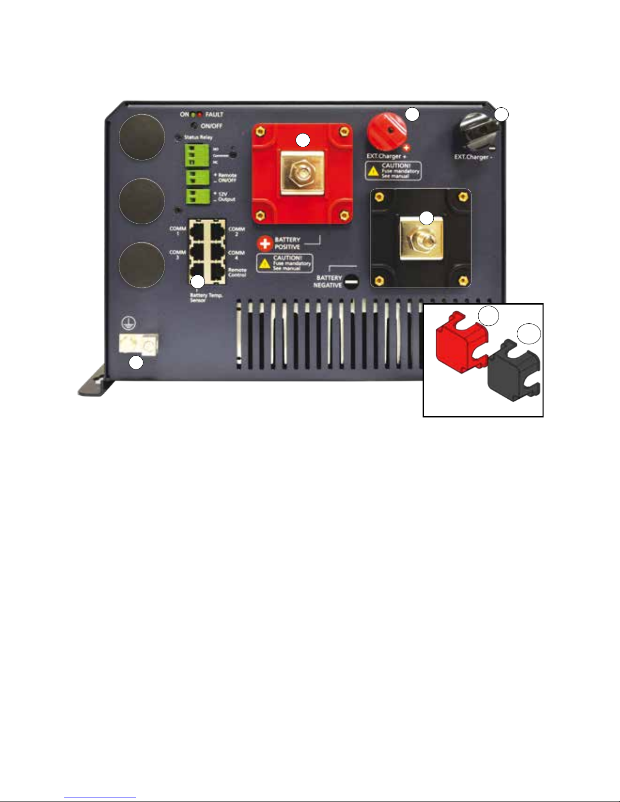
3.5 DC SIDE CONNECTIONS
1. Battery Positive (+) Input Connector – M10 x 1.25 Nut & Bolt (RED Protection Cover 1(a) is Removed)
1a. RED Protection Cover For Battery Positive (+) Input Connector
2. Battery Negative (-) Input Connector – M10 x 1.25 Nut & Bolt (Black Protection Cover 1(b) is Removed)
2a.Black Protection Cover for Battery Negative (-) Input Connector
3. External Charger (+) Input Connector – M12 x 0.75 Thumb Nut and Bolt
4. External Charger (-) Input Connector - M12 x 0.75 Thumb Nut and Bolt
5. DC Side Grounding Connector – Hole Dia 6.5mm for up to 25mm2 (AWG #4). Set Screw M-8. This is
internally connected to the metal chassis of the unit
6. RJ-45 Jack for Battery Temperature Sensor EVO-BCTS
The following DC side connections are required to be made (see Fig 3.8):
Deep cycle batteries are connected to the battery input terminals (1) and (2). The terminals
are provided with protective covers – RED for Positive and BLACK for Negative. Fit these
covers once connections have been made. For details on sizing and charging of batteries,
please refer to Section 1.4 under "General Information-Lead Acid Batteries".
Use appropriate external fuse (Refer to Table 3.1) within 7” of battery Positive terminal.
External charging source, if any, is connected to the connectors (3) and (4) as shown
above. The maximum capacity of the external charging source is 50A.
Battery Temperature Sensor EVO-BCTS is connected to the RJ-45 Jack (6). See Fig 2.5 (a)
and 2.5 (b) for details.
SECTION 3 | Installation
1
3 4
5
2
1a Red
1b Black
6
Protection Covers for Battery Terminals
Fig 3.8 DC Side Connections
Page 36
36 | SAMLEX AMERICA INC.
DC Side Grounding Connector (5) is connected to the Earth ground / vehicle chassis
ground as follows using minimum AWG #6 wire size:
(i) to the Bus Bar "G-B" of the DC Electrical Panel (Fig 3.12)
(ii) to the Bus Bar "G-B" of the Grid Electrical Panel (Fig 3.13)
(iii) to the RV chassis ground in RV (Figs 3.14A and 3.14B)
3.5.1 Preventing DC Input Over Voltage
It is to be ensured that the DC input voltage of this unit does not exceed 17 VDC for the 12V battery
version EVO-2212 and EVO-3012, and 35 VDC for the 24V battery versions EVO-2224 and EVO-4024 to
prevent permanent damage to the unit.
3.5.2 Preventing Reverse Polarity On The Input Side
!
CAUTION!
When making battery connections on the input side, make sure that the polarity of battery
connections is correct (Connect the Positive of the battery to the Positive terminal of the unit
and the Negative of the battery to the Negative terminal of the unit). If the input is connected
in reverse polarity, external DC fuse in the input side will blow and may also cause permanent
damage to the inverter.
Damage caused by reverse polarity is not covered by warranty.
3.5.3 Connection From Batteries / External Charge Controller To The DC Input
Side – Sizing of Cables And Fuses
WARNING!
The input section of the inverter has large value capacitors connected across the
input terminals. As soon as the DC input connection loop (Battery (+) terminal → Fuse
→ Positive input terminal of EVO → Negative input terminal of the EVO → Battery
(–) terminal) is completed, these capacitors will start charging and the unit will
momentarily draw very heavy current that will produce sparking on the last contact in
the input loop even when the unit is in powered down condition.
Ensure that the fuse is inserted only after all the connections in the loop have been
completed so that sparking is limited to the fuse area.
Flow of electric current in a conductor is opposed by the resistance of the conductor. The resistance
of the conductor is directly proportional to the length of the conductor and inversely proportional to
its cross-section (thickness). The resistance in the conductor produces undesirable effects of voltage
drop and heating. The size (thickness / cross-section) of the conductors is designated by AWG
(American Wire Gauge). Conductors thicker than AWG #4/0 are sized in MCM/kcmil.
Conductors are protected with insulating material rated for specic temperature e.g. 90˚C/194˚F. As
current ow produces heat that affects insulation, there is a maximum permissible value of current
(called “Ampacity”) for each size of conductor based on temperature rating of its insulation. The
insulating material of the cables will also be affected by the elevated operating temperature of the
terminals to which these are connected. Ampacity of cables is based on UL-1741 and the National
Electrical Code (NEC)-2014. Please see details given under “Notes for Table 3.1”.
SECTION 3 | Installation
Page 37
The DC input circuit is required to handle very large DC currents and hence, the size of the
cables and connectors should be selected to ensure minimum voltage drop between the battery
and the inverter. Thinner cables and loose connections will result in poor inverter performance
and will produce abnormal heating leading to risk of insulation melt down and re. Normally,
the thickness of the cable should be such that the voltage drop due to the current & the
resistance of the length of the cable should be less than 2%. Use oil resistant, multi-stranded
copper wire cables rated at 90º C minimum. Do not use aluminum cable as it has higher
resistance per unit length. Cables can be bought at a marine / welding supply store.
Effects of low voltage on common electrical loads are given below:
• Lighting circuits - incandescent and Quartz Halogen: A 5% voltage drop causes an
approximate 10% loss in light output. This is because the bulb not only receives less power,
but the cooler lament drops from white-hot towards red-hot, emitting much less visible light.
• Lighting circuits - uorescent: Voltage drop causes a nearly proportional drop in light
output.
• AC induction motors - These are commonly found in power tools, appliances, well pumps
etc. They exhibit very high surge demands when starting. Signicant voltage drop in these
circuits may cause failure to start and possible motor damage.
• PV battery charging circuits - These are critical because voltage drop can cause a
disproportionate loss of charge current to charge a battery. A voltage drop greater than 5%
can reduce charge current to the battery by a much greater percentage.
!
ATTENTION!
Quand vous faites des connexions à la batterie du côté d’entrée, veuillez assurer que les polarités sont mise du bon côté
(Lié le positif de la batterie à la borne positive de l’appareil et le négatif de la batterie à la borne négative de l’appareil. Si
les polarité de l’entrée sont mise à l’envers, le fusible CC externe du côté d’entrée va s’exploser et peut causer des dégâts
permanent à l’onduleur.
Des dégats causés par un renversement des polarités n’est pas couverts par la garantie.
ATTENTION!
La section d’entrée de l’onduleur a des condensateurs de grande valeur qui sont connecté aux bornes
d’entrées. Tant que le boucle de connexion d’entrée CC (la borne (+) de la batterie → le fusible la borne →
d’entrée positive du EVO → la borne d’entrée négative du EVO → la borne (-) de la batterie est complèt,
les condesateurs commençeront à recharger. L’appareil prendra un courant fort brièvement pour s’alimenter
qui va produire une étincelle sur le dernier contact du boucle d’entrée même si l’interrupteur ON/OFF du
l’onduleur est dans la position OFF.
Assurez que le fusible est insèrer seulement après que toutes les connexions sont faites dans le boucle pour
que des étincelles se produisent seulement à l’endroit du fusible.
Le ux du courant dans un conducteur est opposé par la résistance du conducteur. La résistance du conducteur est
corrélative à la longueur du conducteur et inversement corrélatif à son diamètre (l’épaisseur). La résistance dans un
conducteur produit des effects indésirables comme une perte de tension et une surchaffe. La taille (l’épaisseur) des
conducteurs est classée par le AWG (American Wire Guage). Les conducteurs qui sont plus épais que la taille AWG #4/0
sont classé par MCM/kcmil.
SECTION 3 | Installation
Page 38

38 | SAMLEX AMERICA INC.
Les conducteurs sont protègés par des matériaux isolants classés pour une température spécique, par exemple,une
température de 90˚C/194˚F. Le ux de courant produit de la chaleur et affecte l’isolation. Alors, il y a une valeur de
courant maximale (aussi appellé « L’ampacité ») qui est permise pour chaque taille de conducteur et pour la classication
température de l’isolation. Les matériaux isolants des câbles seront aussi affecter par la température de fonctionnement
élèvée des bornes, à qui ils sont connectés. L’ampacité des câbles est basé sur UL-1741 et la Norme Nationale Électrique
(NEC)-2014. « Notes for table 3.1 »
Le circuit d’entrée CC doit subir à des courants CC forts et ainsi, il faut que la taille des câbles et des connecteurs
est sélectionnée pour réduire la perte de tension entre la batterie et l’onduleur. Avec des câbles moins épais et des
connexions lâches la performance de l’onduleur est diminuée et en plus, ça pourrait produire une réchauffement
anormale qui risque de fondre l’isolation ou commencer un incendie. Normalement, il faut que le câble soit assez épais
pour réduire la perte de tension, dû au courant/ la résistance du câble, à moins que 2%. Utilisez des câble multiliares
(ls en cuivre et résistant à l’huile) qui sont classés au moins à 90º C. N’utilisez pas des câbles en aluminium car ils ont une
résistance plus haute (par la longueur de l’unité). On peut achèter des câbles aux magasins de fournitures pour marin/
soudage.
Les effets d’une faible tension pour des charges électriques communes
- Circuits d’allumage - incandescent et Halogène Quartz: Une perte de tension à 5% causera une perte de 10% de la
lumière émise. Cet effet est grâce à deux choses, non seulement l’ampoule reçoive moins de puissance mais, aussi le
lament refroidi change de la chaleur-blanc à la chaleur-rouge, qui émet moins de lumière visible.
- Circuits d’allumage - uorescent: la perte de tension est presque proportionelle à la perte de la lumière émise.
- Moteurs à Induction CA - Souvent, Ils font partie des outils électriques, des dispositifs, pompe à puits, etc. Au
démarrage, ils exigent une surcharge de puissance. Si la tension baisse trop, ils pourraient pas marcher et même
seront endommager.
- Circuit de rechargement de batterie PV - La perte de tension pourrais causer une perte de puissance
disproportionée. Par exemple, une perte de tension à 5% peut réduire le courant de charge par une pourcentage
beaucoup plus grande que 5%.
3.5.4 Fuse Protection In The Battery Circuit
A battery is an unlimited source of current. Under short circuit conditions, a battery can supply
thousands of Amperes of current. If there is a short circuit along the length of the cables that
connects the battery to the inverter, thousands of Amperes of current can ow from the battery
to the point of shorting and that section of the cable will become red-hot, the insulation will
melt and the cable will ultimately break. This interruption of very high current will generate a
hazardous, high temperature, high-energy arc with accompanying high-pressure wave that
may cause re, damage nearby objects and cause injury. To prevent occurrence of hazardous
conditions under short circuit conditions, the fuse used in the battery circuit should limit the
current (should be "Current Limiting Type"), blow in a very short time (should be Fast
Blow Type) and at the same time, quench the arc in a safe manner. For this purpose, UL Class
T fuse or equivalent should be used (As per UL Standard 248-15). This special purpose
current limiting, very fast acting fuse will blow in less than 8 ms under short circuit conditions.
Appropriate capacity of the above Class T fuse or equivalent should be installed within
7” of the battery Plus (+) Terminal (Please see Table 3.1 for fuse sizing).
Marine Rated Battery Fuses, MRBF-xxx Series made by Cooper Bussmann may also be used.
These fuses comply with ISO 8820-6 for road vehicles.
SECTION 3 | Installation
Page 39
It is mandatory to use appropriately sized external fuse in the battery and External Charger
Circuits. If external fuse is not used and reverse polarity connection is made by oversight, the input
section of the unit will be damaged/burnt. Warranty will be voided in such a situation.
Il est obligatoire d’utiliser un fusible externe de taille appropriée à la batterie et les circuits chargeur externe . Si le fusible
externe est pas utilisé et les inversions de polarité est faite par la surveillance , la section d’entrée de l’unité est endommagée / brûlé . La garantie sera annulée dans une telle situation .
3.5.5 DC Input Connection for Battery
Battery is connected to terminals 1, 2 shown in Fig 3.8. The terminal consists of M10 Stud &
Nut. Tightening torque for the nut is 70 kgf.cm (5 lbf.ft). Sizes of cables and fuses are shown
in Table 3.1. Sizing is based on safety considerations specied in UL-1741 and NEC-2014. See
details under “Notes for Table 3.1”.
3.5.6 DC Input Connection for External Charger
External charger is connected to terminals consisting of M12 Stud with Thumb Nut (3, 4 in Fig. 5.3).
- Max current fed through these terminals should be < 50A
- Use wire size given in Table 3.1.
- Tightening torque for the Thumb Nut is 35 kgf.cm (2.5 lbf.ft)
- Use 70A fuse in series with the Positive wire to protect against short circuit along the length
of the connecting wires.
Fuse should be close to the Positive Input Terminal 3.
SECTION 3 | Installation
Page 40
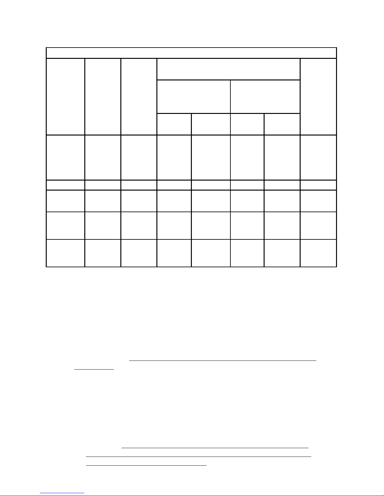
40 | SAMLEX AMERICA INC.
TABLE 3.1 SIZING OF BATTERY SIDE CABLES AND EXTERNAL BATTERY SIDE FUSES
Item
(Column 1)
Rated
Continuous
DC Input
Current
(See Note
1)
(Column 2)
NEC
Ampac-
ity = 125%
of Rated
DC Input
Current at
Column 2
(See Note
2)
(Column 3)
90°C Copper Conductor. Size Based on NEC Ampacity at
Column (3) or 2%Voltage Drop, whichever is Thicker (See
Note 3)
External
Fuse Based
on NEC
Ampacity
at Column
(3) (See
Note 4)
(Column 9)
Cable Running Distance
between the Unit and the
Battery
(Cable Routing In Free Air)
Cable Running Distance
between the Unit and the
Battery
(Cable Routing In Race-
way)
Up to 5 ft.
(Column 5)
Up to 10 ft.
(Column 6)
Up to 5 ft.
(Column 7)
Up to 10 ft.
(Column 8)
EVO-2212 266A 333A AWG#3/0
AWG #4/0
(This size,
based on 2%
voltage drop,
is thicker than
NEC based
size)
2 X AWG
#4/0
(MCM 350)
2 X AWG
#4/0
(MCM 350)
350A
EVO-2224 133A 166A AWG #2 AWG #2 AWG #1/0 AWG #1/0 175A
EVO-3012 373A 466A
2 X AWG
#3/0
(MCM 300)
2 X AWG #3/0
(MCM 300)
Not recom-
mended
Not recom-
mended
500A
EVO-4024 266A 333A AWG#3/0
AWG #4/0
(2% voltage
drop is
thicker)
2 X AWG
#4/0
(MCM 350)
2 X AWG
#4/0
(MCM 350)
350A
External
Charger
50A 63A
AWG #6
(2% voltage
drop is
thicker)
AWG #2
(2% voltage
drop is thicker)
AWG #6
AWG #2
(2% voltage
drop is
thicker)
70A
NOTES FOR TABLE 3.1 - SIZING OF BATTERY SIDE CABLES AND EXTERNAL BATTERY
SIDE FUSES
1) Column 2 indicates the Rated Continuous DC Input Current drawn from the
battery in Inverter Mode
2) Column 3 indicates NEC Ampacity based on which cable conductor sizes
(Columns 5 to 8) are determined. NEC Ampacity is not less than 125% of
the Rated Continuous DC Input Current (Column 2) - Refer to NEC-2014
(National Electrical Code) - Section 215.2(A)(1)(a) for Feeder Circuits.
3) Columns 5 to 8 indicate cable conductor size that is based on the following
2 considerations. Thicker conductor out of the following 2 considerations has
been chosen:
a) As per guidelines in NEC-2014 (National Electrical Code) - Ampacity Table
310.15(B)(16) for Raceway and Ampacity Table 310.15(B)(17) for Free
Air. Conductor size is based on (i) NEC Ampacity specied at Column 3,
(ii) Copper conductor with temperature rating of 90°C and (iii) Ambient
temperature of 30°C / 86°F
b) Voltage drop across the length of cables has been limited to 2% of 12V
/ 24V. Voltage drop has been calculated by multiplying the Rated DC
Input Current (Column 2) and the resistance of the total length of Copper
conductor (the total length of conductor has been taken as 2 times the
running distance between the unit and the battery to cover 2 lengths of
Positive and Negative cable conductors).
SECTION 3 | Installation
Page 41

4) Column 9 indicates the size of external fuse in the battery circuit. It is
mandatory to install this fuse within 7” of the battery Positive terminal to
protect the internal DC Input Section of the unit and also to protect the
battery cables against short circuit. Amp rating of the fuse is based on the
following considerations:
a) Not less than NEC Ampacity of 125% of the Rated Continuous DC Input
Current (Column 3) - Refer to NEC-2014 (National Electrical Code) Section 215.3
b) Closest Standard Ampere Rating of Fuse has been used - Refer to NEC-2014
(National Electrical Code) - Section 240.6(A)
c) Where Standard Fuse Rating does not match the required Ampacity of
125% of the Rated Continuous DC Input Current (Column 3), the next
higher Standard Rating of the fuse has been used - Refer to NEC-2014
(National Electrical Code) - Section 240.4(B)
d) Type of fuse: Fast-acting, Current Limiting, UL Class T (UL Standard 248-15)
or equivalent
3.5.7 Using Proper DC Cable Termination
The battery end and the inverter end of the wires should have proper terminal lugs that will
ensure a rm and tight connection. Choose lugs to t the wire size and the stud sizes on the
inverter and battery ends.
3.5.8 Reducing RF Interference
To reduce the effect of radiated interference, shield the wires with sheathing / copper foil /
braiding. For details, refer to Limiting Electro-Magnetic Interference" at Section 1.3.4.
3.5.9 Taping Battery Wires Together To Reduce Inductance
Do not keep the battery wires far apart. Keep them taped together to reduce their inductance.
Reduced inductance of the battery wires helps to reduce induced voltages. This reduces ripple in the
battery wires and improves performance and efciency. For details, refer to Limiting Electro-Magnetic
Interference" at Section 1.3.4.
SECTION 3 | Installation
Page 42
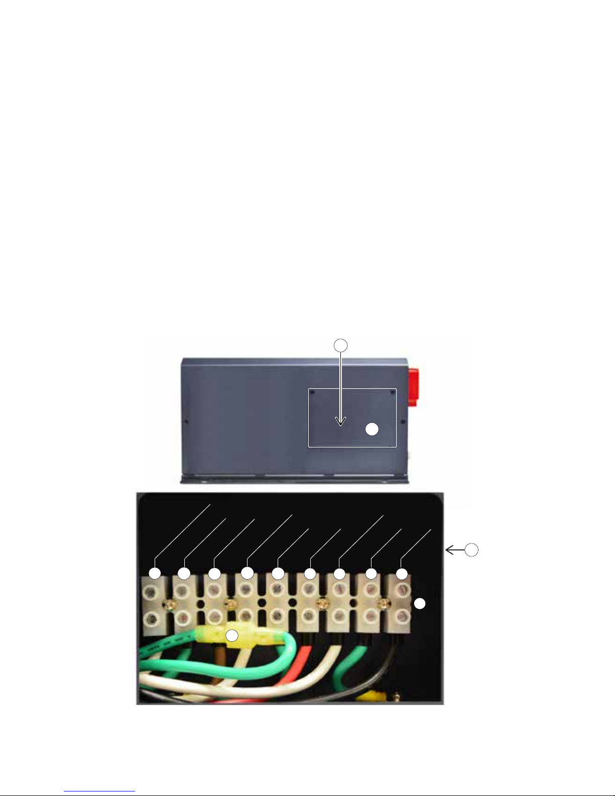
42 | SAMLEX AMERICA INC.
SECTION 3 | Installation
3.6 AC INPUT AND OUTPUT - LAYOUT AND CONNECTION ARRANGEMENT
AC side layout and connection arrangement are shown in Fig 3.9.
1. Cover plate for pocket for AC Input/Output terminals
2. Pocket for AC Input/Output Terminals (behind cover plate 1)
3. AC Input/Output Terminal Block
- Terminal hole diameter: 6mm for up to AWG #6
- Set Screw: M4
4. Grid Input - Line
5. Grid Input - Ground
6. Grid Input - Neutral
7. Generator Input - Line
8. Generator Input - Ground
9. Generator Input - Neutral
10. AC Output - Line
11. AC Output - Ground
12. AC Output - Neutral
13. Male/Female Insulated Quick Disconnect for disabling Ouptut Neutral to chassis Ground bond in
Inverter Mode (Please see Section 4.5.1 to 4.5.3 and Fig 3.1.2)
1
13
3
2
[Behind Cover Plate ]
2
9
10
11
4
8
7
6
5
12
OUTPUT NEUTRAL
OUTPUT GND
OUTPUT LINE
GEN NEUTRAL
GEN GND
GEN LINE
GRID NEUTRAL
GRID GND
GRID LINE
Fig 3.9 AC Input and Output
Page 43
3.6.1 System Grounding and Output Neutral to Chassis Ground Bond Switching
WARNING!
• In "Inverting Mode" (default condition), the Neutral of the AC output of the unit
gets bonded to the metal chassis of the unit through the internal “Neutral to Chassis
Switching Relay” [Relay K4 in Figs 4.1(a) and 4.1(b)].
• In “Charging Mode”, the internal “Output Neutral to Chassis Switching Relay”
disconnects the Neutral of the AC output connection from the chassis of the unit. The
Neutral of the AC output connection of the unit will get bonded to the Earth Ground
through the Neutral to Earth Ground bond in the AC Breaker Panel/Load Center
supplying Grid power / AC output connections of the generator.
• Disabling Neutral to Ground Bond: In some applications, the Output Neutral may be
required to remain isolated from chassis/Ground at all times. For this, automatic Output
Neutral to chassis Ground bond can be disabled by disconnecting the Male/Female
Disconnect (13, Fig 3.9) located in the AC Wiring Compartment.
• System grounding, as required by National / Local Electrical Codes / Standards, is the
responsibility of the user / system installer.
For further details please refer to Sections 4.5.1 to 4.5.3.
ATTENTION!
• En état de défaut, le neutre de la sortie CA de l’unité dans le “Mode de l’onduleur / décharge” obtient lié au
châssis métallique de l’unité à travers la interne “Neutre à châssis relais de commutation”.
• Dans “Mode de chargement”, l’interne “Neutre à châssis relais de commutation” déconnecte le neutre de la
connexion de sortie AC du châssis de l’unité. Le neutre de la connexion de sortie CA de l’unité va obtenir lié à la
terre des masses à travers le neutre à la terre liaison au sol dans le centre de panneau de disjoncteurs AC / charge
alimenter Grille / connexions de sortie CA du générateur.
• Désactivation du lien neutre à mise a terre: Dans certaines applications, il est nécessaire que la sortie neutre soit isolé
du châssis/mise a terre à tout moment. Pour cela, le lien de la sortie automatique neutre au châssis/mise a terre peut être
désactivé en débranchant la connexion male/femme ( 13 , gure 3,9) situé dans le compartiment câblage CA .
• Mise à la terre du système, tel que requis par la National / codes électriques locaux / normes, est de la
responsabilité de l’installateur utilisateur / système.
3.6.2 AC Input Considerations – Voltage And Frequency
The EVO unit is designed to accept 120 VAC, 60 Hz / 50 Hz single phase AC power from
Grid or generator. These 120V versions come preset for 60 Hz operation. Frequency can be
programmed at 50 Hz using optional Remote Control EVO-RC (see Appendix A).
SECTION 3 | Installation
Page 44
44 | SAMLEX AMERICA INC.
3.6.3 Preventing Paralleling of the AC Output
WARNING!
The AC output of the unit cannot be synchronized with another AC source and hence, it is
not suitable for paralleling on the output side. The AC output of the unit should never be
connected directly to an electrical breaker panel / load center which is also fed from another
AC source. Such a connection may result in parallel operation of different power sources
and AC power from the other AC source will be fed back into the unit which will instantly
damage the output section of the unit and may also pose a re and safety hazard. If an
electrical breaker panel / load center is fed from this unit and this panel is also required to be
powered from additional alternate AC source, the AC power from the additional AC source
should rst be fed to a suitable Manual/Automatic Transfer Switch and the output of the
transfer switch should be connected to the electrical breaker panel / load center. To prevent
possibility of paralleling and severe damage to the inverter, never use a simple jumper cable
with a male plug on both ends to connect the AC output of the inverter to a handy wall
receptacle in the home / RV.
ATTENTION!
La sortie de courant alternatif de l’unité ne peut pas être synchronisée avec une autre source de courant alternatif et,
par conséquent, il ne convient pas pour mise en parallèle du côté de la sortie. La sortie AC de l’unité ne doit jamais
être connecté directement à un panneau central / de charge disjoncteur électrique qui est également alimenté par
une autre source de courant alternatif. Une telle connexion peut entraîner un fonctionnement parallèle de différentes sources d’énergie et la puissance AC de l’autre source de courant alternatif est réinjecté dans l’unité qui va instantanément endommager la section de sortie de l’unité et peuvent aussi poser un risque d’incendie et de sécurité.
Si un centre panneau de disjoncteur électrique / charge est alimentée à partir de cette unité et ce panneau est également nécessaire pour être alimenté à partir de suppléant supplémentaire source de courant alternatif, l’alimentation
de la source de courant alternatif supplémentaire doit d’abord être introduit dans un manuel approprié / commutateur de transfert automatique et le sortie du commutateur de transfert doit être relié au centre panneau / de la
charge électrique du disjoncteur. Pour éviter possibilité de mise en parallèle et de graves dommages à l’onduleur, ne
jamais utiliser un câble de raccordement simple avec une che mâle sur les deux extrémités pour raccorder la sortie
AC de l’onduleur à une prise murale à portée de main à la maison / RV.
3.6.4 Connecting to Multi-wire Branch Circuits
DO NOT dir
ectly connect the Hot side of the 120 VAC of the unit to the two Hot Legs of the
120 / 240 VAC Breaker Panel / Load Center where Multi-wire (common Neutral ) Branch Circuit
wiring method is used for distribution of AC power. This may lead to overloading / overheating
of the Neutral conductor and is a risk of re.
A split phase transformer (Isolated or Auto-transformer) of suitable VA rating (25 % more than
the VA rating of the unit) with Primary of 120 VAC and Secondary of 120 / 240 VAC (Two 120
VAC split phases 180 degrees apart) should be used. The Hot and Neutral of the 120 VAC
output of the inverter should be fed to the Primary of this transformer and the 2 Hot outputs
(120 VAC split phases) and the Neutral from the Secondary of this transformer should be
connected to the Electrical Breaker Panel / Load Center.
> White Papers).
SECTION 3 | Installation
Page 45
3.7 AC INPUT & OUTPUT WIRING
WARNING!
Please ensure that the AC input voltage from the Grid / Generator is connected to
the AC input terminals and not to the AC output terminals and that this connection is
made only when the unit is in OFF condition.
Please note that when the unit is powered on, a Self Test is carried out which includes a check
if the AC input voltage from the Grid / Generator connection has been erroneously connected
to the AC output terminals instead of AC input terminals. If this wrong connection is detected,
(voltage > 10 VAC is seen on terminals OUTPUT LINE & OUTPUT NEUTRAL at the time of
switching on of the unit), the unit will not be powered on and a message “Output Fault” will
be displayed. This protection against error in connection of the AC input wiring is active only
when this wrong connection is made when the unit is in OFF condition and is switched ON
subsequently.
If the AC input voltage from the Grid / Generator is erroneously connected / fed to the
AC output connections when the unit is ON condition, the above protection will not
work and the Inverter Section will be burnt instantaneously and may become a re
hazard.
ATTENTION!
Se il vous plaît faire en sorte que la tension d’entrée d’alimentation de la grille / générateur est reliée aux
bornes d’entrée de courant alternatif, et non aux bornes de sortie à courant alternatif et que cette connexion
est établie uniquement lorsque l’appareil est dans un état hors tension.
Se il vous plaît noter que lorsque l’appareil est sous tension, un auto-test est effectué qui inclut un contrôle si la tension
d’entrée CA de la connexion réseau / générateur a été à tort connecté aux bornes de sortie CA à la place de bornes
d’entrée AC. Si cette mauvaise connexion est détectée, (tension> 10 V ca se voit sur les bornes de sortie LINE et neutre
de sortie au moment de la mise sous tension de l’appareil), l’unité ne sera pas allumé et un message “Sortie défaut” sera
afché. Cette protection contre les erreurs dans le cadre du câblage d’alimentation est active uniquement lorsque cette
mauvaise connexion est établie lorsque l’appareil est en état hors et est allumé par la suite.
Si la tension d’entrée CA de la Grille / générateur est erronée connecté / nourri aux connexions de sortie CA
lorsque l’appareil est en état , la protection ci-dessus ne fonctionnera pas et la Section de l’onduleur sera brûlé
instantanément et peut devenir un risque d’incendie.
3.7.1 AC Input/Output Supply Connections
The AC input and output supply connections are located in a pocket protected by a cover with
a removable front plate (1,2 Fig 3.9). Three 27.8mm / 1
3/
32
” diameter holes (10A to 10C, Fig
2.1) have been provided for cable / conduit entry. Remove the caps covering the holes and
install appropriate ¾” Trade Size Fitting for routing the AC input and output wires/conduits.
Screw down type of terminal block (3, Fig 3.9) is used for connecting the wires. The hole size
for wire entry is 6 mm and set screw size is M4. It can accommodate conductors with solid or
multi-stranded wire size range of AWG #6 to AWG #20.
Strip adequate insulation from the end of the wire (Fig. 3.11). Avoid nicking the wire when
stripping the insulation. Wire End Terminals have been provided (see Section 2.6, page 28) for
rm connection under the set screw. Insert the bare end of the wire into the barrel portion of
the Wire End Terminal & crimp barrel portion using suitable crimping tool (Fig 3.11).
SECTION 3 | Installation
Page 46
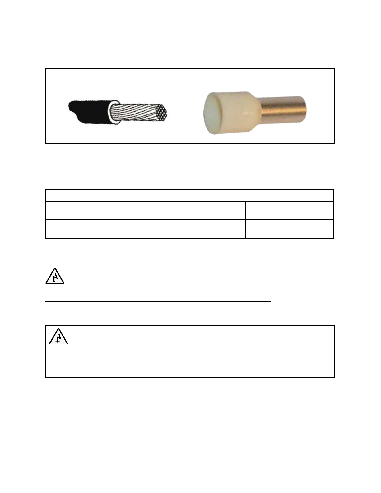
46 | SAMLEX AMERICA INC.
Stripped Wire End
Wire End Terminal
Crimp Barrel Portion
↓
→
Insert the terminated end of the wire fully into the terminal slot till it stops. Tighten the screw
rmly. Tightening torque for the screws – 7 to 12 Kgf*cm / 0.5 to 0.9 lbf*ft.
Fig 3.11 Stripped Wire End Terminal on AC Wiring
3.7.2 Tightening Torques
Tightening torques to be applied to the wiring terminals are given in Table below:
TIGHTENING TORQUES
Battery Input
Connectors
External Charger Input
Connectors
AC Input and Output
Connectors
70 kgf.cm
(5.0 lbf.ft)
35 kgf.cm
(2.5 lbf.ft)
7 to 12 kgf.cm
(0.5 to 0.9 lbf.ft)
3.8 SIZING OF WIRING AND BREAKERS - AC INPUT SIDE
WARNING!
AC Breakers for the AC input circuits have NOT been provided internally. These have to be
provided externally by the installer / user based on guidelines given below. Please note that
guidelines given below on wire sizing and over-current protection will be superseded by the
applicable National / Local Electrical Codes.
ATTENTION!
Breakers AC pour les circuits d’entrée AC ont pas été fournis en interne. Ceux-ci doivent être fournies à l’extérieur par
l’installateur / utilisateur sur la base des directives données ci-dessous. Se il vous plaît noter que les directives ci-dessous
sur dimensionnement des câbles et protection contre les surintensités seront remplacées par les nationaux / codes
électriques locaux applicables.
3.8.1 Tables for Wire and Breaker Sizing - AC Input Side
Tables 3.2.1 to 3.2.3 provide details of wire and breaker sizing for the AC input side.
Table 3.2.1: For EVO-2212, 2224, 3012 and 4024 for AC Input Current Limit ("GRID
MAX CURRENT" / "GEN MAX CURRENT") set at 30A (Default Setting)
Table 3.2.2: For EVO-2212, 2224, 3012 and 4024 for full rated AC input currents.
SECTION 3 | Installation
Page 47
AC input side wiring and breaker sizes depend upon the maximum continuous AC input current under various operating conditions described in the succeeding paragraphs.
The Maximum Load Current on the output side has to be limited to the rated output Amp
capacity of the specic model when operating in Inverter Mode (Column 1 ).
When Grid / Generator input is available and the unit is operating in Charging / Pass
Through Mode, the AC Input Current will be determined as follows:
The maximum possible AC Input Current (Column 4) for a particular model will be
equal to the sum of the Rated AC Side Battery Charging Current (Column 3) and the
Rated Pass Through current (Column 2). Rated Pass Through Current (Column 2) = the
Rated Output Current in Inverter Mode (Column 1).
The AC Input current in Charging / Pass Through Mode will be restricted by the
maximum Amp rating of the Generator or the Amp rating of the breaker in the Grid
Branch Circuit that is feeding the unit. The AC Input Current drawn by the unit can be
programmed to the desired limit (Column 5) to match the output Amp rating of the
Generator or the Amp rating of breaker in the Grid Branch Circuit. Optional Remote
Control EVO-RC is required to change this limit (See Appendix A, Section 4.5 for Input
Settings - "GRID MAX CURRENT" / "GEN MAX CURRENT"). All the 4 models EVO2212, 2224, 3012 and 4024 come with the "GRID MAX CURRENT" / "GEN MAX
CURRENT" set at 30A (Default Setting). See Table 3.2.1.
Higher Power Models will require higher Amp rating of the Generator / the Grid Branch
Circuit. Wiring and breaker sizing for the full rated AC input currents for EVO-2212,
2224, 3012 and 4024 are given at Table 3.2.2.
TABLE 3.2.1 SIZING OF GRID AND GENERATOR INPUT WIRING AND BREAKERS (FOR DEFAULT INPUT
CURRENT LIMIT PROGRAMMED AT 30A FOR EVO-2212, EVO-2224, EVO-3012, EVO-4024)
Model No. and
Rated Output
Power in In-
verter Mode
(Column 1)
Rated
AC Pass
Through
Current
(See Note
1)
(Column 2)
Rated AC
Charging
Current
(See Note
2)
(Column 3)
Total Rated
AC Input
Current
(Columns
2 +3)
(See Note 3)
(Column 4)
Pro-
grammed
AC Input
Current
Limit
[GRID MAX
CURRENT/
GEN MAX
CURRENT]
(See Note 4)
(Column 5)
NEC Ampac-
ity = 125% of
Column 5
(See Note 5)
(Column 6)
Conductor
Size Based
on NEC
Ampacity at
Column 6
(See Note 6)
(Column 7)
External
Breaker
Size
Based
on NEC
Ampacity at
Column 6
(See Note 7)
(Column 8)
EVO-2212
(2200VA, 18A)
18 A 15A 33A
30A
(Default)
37.5A AWG #8 40A
EVO-2224
(2200VA, 18A)
18A 19A 37A
EVO-3012
(3000VA, 25A)
25A 20A 45A
EVO-4024
(4000VA, 33A)
33A 29A 62A
SECTION 3 | Installation
Page 48
48 | SAMLEX AMERICA INC.
i
INFO for Table 3.2.1 (Column 8)
AC input breaker size of 40A (Column 8) and corresponding AC input wire size of
AWG #8 (Column 7) for all the 4 models is based on the default AC input current limit
of 30A (Column 7). The AC input current limit in EVO is a programmable parameter
specied as "GRID MAX CURRENT" and "GEN MAX CURRENT" (see Section 4.5 of
Owner's Manual for Remote Control EVO-RC at Appendix - A). The 30A default AC
input current has been used to match the standard 30A mains power inlet plug (using
30A cord) on motorhomes / RVs.
For using the full rated AC input current capacities of the 4 models (Column 4), higher
AC input current limits ("GRID MAX CURRENT" / "GEN MAX CURRENT") will have to
be programmed using the optional Remote Control Model EVO-RC. AC input breakers
and AC input wiring sizes will also change. In this regard, please refer to Table 3.2.2.
TABLE 3.2.2 SIZING OF GRID AND GENERATOR INPUT WIRING AND BREAKERS FOR FULL RATED
AC INPUT CURRENTS FOR EVO-2212, EVO-2224, EVO-3012, EVO-4024
Model No. and
Rated Output
Power in In-
verter Mode
(Column 1)
Rated
AC Pass
Through
Current
(See Note
1)
(Column 2)
Rated AC
Charging
Current
(See Note
2)
(Column 3)
Total Rated
AC Input
Current
(Columns
2 +3)
(See Note 3)
(Column 4)
Pro-
grammed
AC Input
Current
Limit
[GRID MAX
CURRENT/
GEN MAX
CURRENT]
(See Note 4)
(Column 5)
NEC Ampac-
ity = 125% of
Column 5
(See Note 5)
(Column 6)
Conductor
Size Based
on NEC
Ampacity at
Column 6
(See Note 6)
(Column 7)
External
Breaker
Size
Based
on NEC
Ampacity at
Column 6
(See Note 7)
(Column 8)
EVO-2212
(2200VA, 18A)
18 A 15A 33A 33A 41.25A AWG #8 45A
EVO-2224
(2200VA, 18A)
18A 19A 37A 37A 46.25A AWG #8 50A
EVO-3012
(3000VA, 25A)
25A 20A 45A 45A 56.25A AWG #6 60A
EVO-4024
(4000VA, 33A)
33A 29A 62A 62A 77.5A
AWG #4 or
2X AWG #6
80A
NOTES FOR TABLES 3.2.1 AND 3.2.2 - SIZING OF GRID AND GENERATOR INPUT
WIRING AND BREAKERS
1) Column 2 indicates the Rated AC Pass Through Current when in Charger / Pass
Through Mode (value of this current = Rated AC Output Current in Inverter Mode).
2) Column 3 indicates the Rated AC Side Charging Current in Charger / Pass Through
Mode.
3) Column 4 indicates the total Rated AC Input Current which is the sum of the Rated
AC Pass Through Current (Column 2) and the Rated AC Side Charging Current
(Column 3).
SECTION 3 | Installation
Page 49

4) Column 5 indicates the Programmed AC Input Current Limit. The value of this cur-
rent limit is called "GRID MAX CURRENT" / "GEN MAX CURRENT" for programming
purposes and is programmable using the optional Remote Control Model EVO-RC
(See Appendix A, Section 4.5 for Input Settings -"GRID MAX CURRENT" / "GEN
MAX CURRENT"). Appropriate value can be programmed to match the available
capacity of the Grid input AC Branch Circuit or the rated capacity of the Generator.
Default value for all the 4 models is 30A and is based on convenience of powering these units from the standard 30A main power inlet plug (wiring 30A cord) on
motorhomes / RVs.
5) Column 6 indicates NEC Ampacity based on which the wiring conductor size
(Column 7) is determined. This NEC Ampacity is not less than 125% of the
Programmed AC Input Current Limit (Column 5) - Refer to NEC-2014 (National
Electrical Code) - Section 210.19(A)(1)(a) regarding minimum Ampacity and size of
Branch Circuit Conductors.
6) Column 7 indicates the wiring conductor size that has been determined based on
NEC-2014 (National Electrical Code) - Ampacity Table 310.15(B)(16) for Raceway.
This conductor size is based on (i) NEC Ampacity (Column 6) (ii) conductor
temperature of 75°C / 167°F and (iii) ambient temperature of 30°C / 86°F.
7) Column 8 indicates the Amp rating of EXTERNAL breaker that is required to be
installed in the Load Center / Breaker Panel feeding the unit. The Amp rating of
this breaker is based on the following considerations:
a. Not less than the NEC Ampacity (Column 6) - Refer to NEC-2014 (National
Electrical Code) - Section 210.20(A) regarding overcurrent protection of
Branch Circuit Conductors. However, the Amp rating of the fuse has to be
≤ the Ampacity of wire size at Column 7 based on Table 310.15(B)(16) for
Raceway (conductor temperature of 75°C / 167°F and ambient temperature of
30°C / 86°F).
b. Closest Standard Ampere Rating of Breaker has been used - Refer to NEC-2014
(National Electrical Code) - Section 240.6(A) regarding overcurrent protection
c. Where Standard Breaker Rating does not match the required NEC Ampacity
(Column 6), the next higher Standard Rating of the breaker has been used Refer to NEC-2014 (National Electrical Code) - Section 240.4(B) regarding over
current devices
d. Type of breaker: Standard circuit breaker for 120VAC Load Center /Breaker Panel
3.9 SIZING OF WIRING AND BREAKERS - AC OUTPUT SIDE
WARNING!
AC Breakers for the AC output circuits have NOT been provided internally. These have to be
provided externally by the installer / user based on guidelines given below. Please note that
guidelines given below on wire sizing and over-current protection will be superseded by the
applicable National / Local Electrical Codes.
SECTION 3 | Installation
Page 50
50 | SAMLEX AMERICA INC.
ATTENTION!
Breakers AC pour les circuits d’entrée AC ont pas été fournis en interne. Ceux-ci doivent être fournies à l’extérieur par
l’installateur / utilisateur sur la base des directives données ci-dessous. Se il vous plaît noter que les directives ci-dessous
sur dimensionnement des câbles et protection contre les surintensités seront remplacées par les nationaux / codes
électriques locaux applicables.
3.9.1 Tables for Wire and Breaker Sizing - AC Output Side
Table 3.3 provides details of wire and breaker sizing for the AC output side.
AC wiring and breaker sizes on the AC output side are required to be determined by the
Rated Load Current when operating in Inverter Mode (Column 1).
Table 3.3
SIZING OF AC OUTPUT WIRING AND BREAKERS
Item Model No.
and
Rated Output
Power in Inverter
Mode
(Column 1)
Rated AC Out-
put Current in
Inverter Mode
(See Note 1)
(Column 2)
NEC Ampac-
ity = 125%
of Column 2
(See Note 2)
(Column 3)
Conductor Size
based on NEC
Ampacity at
Column 3
(See Note 3)
(Column 4)
External Breaker
Size based on
NEC Ampacity at
Column 3
(See Note 3)
(Column 5)
EVO-2212
(2200VA, 18A)
18.33A
22.91 AWG #10 25A
EVO-2224
(2200VA, 18A)
18.33A 22.91 AWG #10 25A
EVO-3012
(3000VA, 25A)
25A 31.25 AWG #8 35A
EVO-4024
(4000VA, 33A)
33.33A 41.66 AWG #8 45A
NOTES FOR TABLE 3.3 - AC OUTPUT WIRING AND BREAKERS
1) Column 2 indicates the Rated AC Output Current in Inverter Mode
2) Column 3 indicates NEC Ampacity based on which the output-wiring conductor
is sized. This NEC Ampacity is not less than 125% of the Rated Output Current in
Inverter Mode (Column 2). - Refer to NEC-2014 (National Electrical Code) - Section
215.2(A)(1)(a) regarding Feeder Circuit Conductors. PLEASE NOTE that when the
unit is operating in Inverter Mode, it is considered to be an AC source that is feeding
power to the Load Center / Breaker Panel on the load side. Hence, the AC output
circuit of the unit is considered to be a Feeder Circuit for purposes of NEC-2014.
3) Column 4 indicates conductor size for the output side wiring. The size is based on
NEC-2014 (National Electrical Code) - Ampacity Table 310.15(B)(16) for Raceway.
Conductor size is based on (i) NEC Ampacity (Column 3), (ii) conductor temperature
of 75°C and (iii) ambient temperature of 30°C / 86°F.
SECTION 3 | Installation
Page 51

4) Column 5 indicates the Amp rating of EXTERNAL breaker that is required to be
installed in the Load Center / Breaker Panel that is being fed from the AC output from
this unit. Amp rating of the breaker is based on the following considerations:
a) Not less than NEC Ampacity (Column 3) - Refer to NEC-2014 (National Electrical
Code) - Section 215.3 regarding over-current protection of Feeder Circuit
Conductors
b) Closest Standard Ampere Rating of Breaker has been used - Refer to NEC-2014
(National Electrical Code) - Section 240.6(A) regarding Standard Ampere Ratings
c) Where Standard Breaker Rating does not match the required NEC Ampacity at
Column 3, the next higher Standard Ampere Rating of the breaker has been used
- Refer to NEC-2014 (National Electrical Code) - Section 240.4(B) regarding over
current devices rated 800 Amps or less
d) Type of breaker: Standard circuit breaker for 120VAC Load Center /Breaker Panel
3.10 GFCI PROTECTION FOR VEHICLE
APPLICATION
When this unit is installed in vehicles, ensure that Ground Fault Circuit Interrupter(s) are installed
in the vehicle wiring system to protect all branch circuits. Details of tested and approved GFCI’s are
given in Table 3.4.
3.11 GROUNDING TO EARTH OR TO OTHER DESIGNATED GROUND
Grounding means connecting (bonding) to Earth Ground or to the other designated Ground.
For example, in a motorhome / caravan, the metal frame of the motorhome / caravan is normally designated as the Negative DC ground / RV Ground. Similarly, all metal portions of boats
and marine craft are bonded together and called Boat Ground.
Grounding is required for (i) protection against damage due to lightning strike and (ii) protection against electric shock due to “Ground Fault”. In case of EVO, “Ground Fault” may occur
due to inadvertent contact between an energized ungrounded current carrying conductor
and exposed metal surface resulting in voltage getting fed to (i) the metal chassis of the EVO
or (ii) to the metal chassis of the devices connected to EVO or (iii) to the metal frame/ chassis
in an RV / motorhome / caravan. When this energized exposed surface is touched, the voltage
will drive current through the body to Earth Ground producing electric shock. When properly
grounded to Earth Ground (or Frame / Chassis Ground in motorhome or caravan), the Leakage Current Protection Device (like RCD, GFCI etc.) or Over Current Protection Device (like
Circuit Breaker or Fuse) will trip and interrupt the circuit feeding power from the AC source
(EVO / Grid / Generator) or the DC source (12V / 24V battery). Proper grounding will ensure
that all exposed metal surfaces will have equal potential and will be bonded to (i) a single
common Earth Ground point i.e. the Ground Rod / buried metallic water / gas pipe at the
premises or (ii) the Frame / Chassis Ground in a motorhome / caravan.
•“GroundedElectricalPowerDistribution"
•“GroundingSystemandLightning/GroundFaultProtection”
SECTION 3 | Installation
Page 52
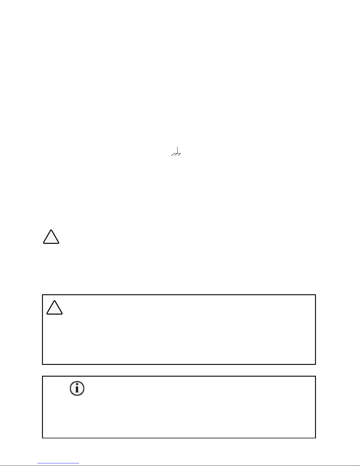
52 | SAMLEX AMERICA INC.
3.12 GROUNDING ARRANGEMENT IN EVO SERIES
Schematic at Fig. 3.12 illustrates the grounding arrangement of EVO Series.
Internally, EVO consists of a DC Section and an AC Section that are isolated through a transformer.
Both these sections are required to be grounded appropriately.
When using a generator, please ensure that the Neutral of the generator is bonded to the metal
frame of the generator and the metal frame of the generator is bonded to Earth Ground through
the Grounding Electrode (GE) i.e. the Ground Rod.
3.13 DC SIDE GROUNDING (SEE FIG. 3.12)
DC side grounding involves bonding of the metal frame/chassis of EVO, the metal chassis
of the DC Electrical Panel and the Battery Negative Terminal to Earth Ground in shore based
installation or to the metal frame / “Chassis
” of the motorhome / caravan. This ensures
that in case of a ground fault in the +12V / +24V circuit, the fuse in the +Battery line blows
to clear the fault. This fuse in the +Battery line has Ampere capacity matching the rated DC
input current of the EVO in Inverter Mode i.e. 150A to 400A depending upon the model of
the model of the EVO being used. The wire size used for DC side grounding should be minimum AWG #6 or of the same size as the battery cable, whichever is thicker (Battery cable size
should have minimum Ampacity ≥ the Ampere rating of this battery fuse (150A to 400A) depending upon the model of the EVO being used). This recommendation on sizing of the
DC Side Grounding Wire will be superseded by the National / Local Electrical Codes.
!
CAUTION!
As per American Boat and Yacht Council (ABYC) Standard E-11 for AC and DC Electrical
Systems on Boats, the size of DC side grounding wire shall not be smaller than one size under
that required for current carrying conductors supplying the device. Hence, for application on
EVO on boat / yacht, the size of the DC side grounding conductor should be of the same or
one size smaller than the size of battery cable specied in Table 3.1.
!
ATTENTION!
Selon le « American Boat and Yacht Council » (ABYC) la norme E-11 pour le système électrique CA et CC des bateaux, la
taille du l de mise à la terre du côté CC ne doit pas être inférieure à un format sous celle requise pour les conducteurs
tenant le courant pour alimenter l'appareil. Par conséquent, pour l’application EVO sur le bateau / yacht, la taille du
conducteur de mise a terre côté CC devrait être de la même ou strictement une taille plus petite que la taille du câble de
batterie indiqué dans le tableau 3.1.
INFO
As described at Section 3.14, the metal frame / chassis of the EVO (Fig 3.12, G1) is bonded to the
Earth Ground "GE" (Ground Rod) for AC side grounding. It may be argued that if the metal frame /
chassis of EVO is already bonded to Main Earth Ground "GE" for AC side grounding, why
it is necessary to provide additional DC side grounding wiring? (Wiring that bonds DC Grounding
SECTION 3 | Installation
Page 53

Terminals "G2", "G-B" and GE in Fig 3.12) If separate thicker grounding wire of the
same size as the battery cable was not provided for the DC side grounding and there was a
ground fault in the battery circuit, very large DC fault current from Battery+ would ow through
the smaller size AC grounding wires to the Battery Negative through Earth Ground. These smaller
size AC side grounding wires would be damaged due to very high DC side fault current (150A to
400A depending on the Model of the EVO being used).
A DC Side Grounding Connector (G2) (5 in the DC side layout in Fig. 2.1) is provided for connecting to the System Ground. The connector can accept wire sizes AWG # 4–6. The set screw
size is M8.
A DC Distribution Panel, as shown in Fig. 3.12, is normally provided to connect the batteries
and distribute DC power to the inverter and to the other DC loads.
The Negative of the battery is connected to the Neg (-) Bus of the DC Electrical Panel which, in
turn, is connected to its Grounding Bus Bar (G-B). Grounding Bus Bar G-B of the DC Electrical
Panel is further bonded to the Grounding Bus Bar "G-B" of the Grid Electrical Panel and then to
the Grounding Electrode (GE), also called Ground Rod. Hence, the Battery Negative, the chassis of the DC Electrical Panel and the metal chassis of the EVO will all be bonded to the Earth
Ground.
Connect the DC Grounding Terminal (G2) (5 in the DC side layout in Fig. 3.8), to the Grounding
Bus Bar (G-B) in the DC Electrical Panel using AWG #6 insulated stranded copper wire. Similarly,
use AWG #6 wire to connect the Grounding Bus Bar "G-B" in the DC Electrical Panel to the
Grounding Bus Bar "G-B" in the Grid Electrical Panel. For application of EVO on a boat, the size
of this wire should be of the same size or one size smaller than the battery Negative wire (See
CAUTION! above).
The connections must be tight against bare metal. Use star washers to penetrate paint and
corrosion. As the Equipment Grounding Bus Bar ("G-B") in the DC Electrical Panel is
bonded to the Grounding Electrode (GE) through Grounding Bus Bar "G-B" in the Grid
Electrical Panel, the metal chassis of the EVO will be bonded to Earth Ground for protection against Ground fault on the DC side of EVO.
3.14 AC SIDE GROUNDING (PLEASE SEE FIG 3.12)
• InEVO,theACInputGroundingTerminals{GENGND(8),GRIDGND(5)}andACOuput
Grounding Terminals {OUTPUT GND (11)}, are internally bonded to the metal chassis of the
inverter (G1)
• TheGroundingWiresfromGrid/GeneratorareconnectedtotheACinputGroundterminalsin
EVO {GRID GND (5), GEN GND (8)}.
• TheACoutputGroundwireofEVO{OUTPUTGND(11)}isconnectedtheGroundingBusBar
(G-B) of the Electrical Sub-Panel for EVO.
• TheGroundingBusBar(G-B)oftheElectricalSub-PanelforEVOisconnectedtotheGrounding
Bus Bar (G-B) of the Grid Electrical Panel.
• The AC Ground (E) of the Generator is also connected to the Grounding Bus Bar (G-B) of the
Grid Electrical Panel.
• The Grounding Bus Bar (G-B) of the Grid Electrical Panel is bonded to the Grounding Electrode
(GE) e.i. the Ground Rod.
SECTION 3 | Installation
Page 54

54 | SAMLEX AMERICA INC.
• Thus, in keeping with the NEC requirements, the AC Grounds of EVO, Grid Electrical
Panel and the Generator will be bonded to the Earth Ground only at one single point
at the Grid Electrical Panel feeding the EVO.
3.14.1 SWITCHING OF BONDING OF OUTPUT NEUTRAL TO CHASSIS GROUND
As required by NEC and UL Standard 458, automatic switching of bonding between the Output
Neutral and Chassis Ground has been provided in EVO through “Output Neutral and Chassis
Ground Bond Switching Relay” [K4 in Figs 4.1(a) and 4.1(b)]. Switching is carried as follows:
• Whenoperatingasaninverter,thecurrentcarryingconductoroftheInverterSectionthat
is connected to the Output Neutral terminal of the EVO is bonded to the metal chassis of
EVO by the “Output Neutral to Chassis Ground Bond Switching Relay” [K4 in Figs 4.1(a) and
4.1(b)]. As the metal chassis of EVO is in turn bonded to the Earth Ground (in shore installations) or RV Ground (chassis of the RV) or to the Boat Ground (DC Negative Grounding Bus
Bar and the Main AC Grounding Bus Bar are tied together in a boat and this is called the
“Boat Ground”), this current carrying conductor of the Inverter Section (connected to the
Output Neutral Terminal) will become the Grounded Conductor (GC) or the Neutral of the
Inverter Section.
• WheninChargingMode,theNeutralconductoroftheGridpower/Generatorwillbecon-
nected to the Output Neutral terminal of EVO. At the same time, the “Output Neutral to
Chassis Ground Bond Switching Relay” [K4 in Figs 4.1(a) and 4.1(b)] will unbond (disconnect) the Output Neutral connector of EVO from the metal chassis of EVO. This will ensure
that the Grounded Conductor (GC) i.e. the Neutral of the Grid power/Generator is bonded
to the Earth Ground at one single point at the location of the AC Power Distribution System
of the Marina / RV Park / Shore Power.
• Disabling Neutral to Ground Bond: In some applications, the Output Neutral of EVO
may be required to remain isolated from the chassis/Ground at all times. For this, automatic
Ouput Neutral to Chassis Ground bond can be disabled by disconnecting the Male/Female
Quick Disconnect located in the AC wiring compartment. [Please see (i) 13, Fig 3.9 and
(ii) "QD" in Figs 4.1(a) and 4.1(b)].
- “Neutral to Ground Switching in RV and Marine Application
SECTION 3 | Installation
Page 55
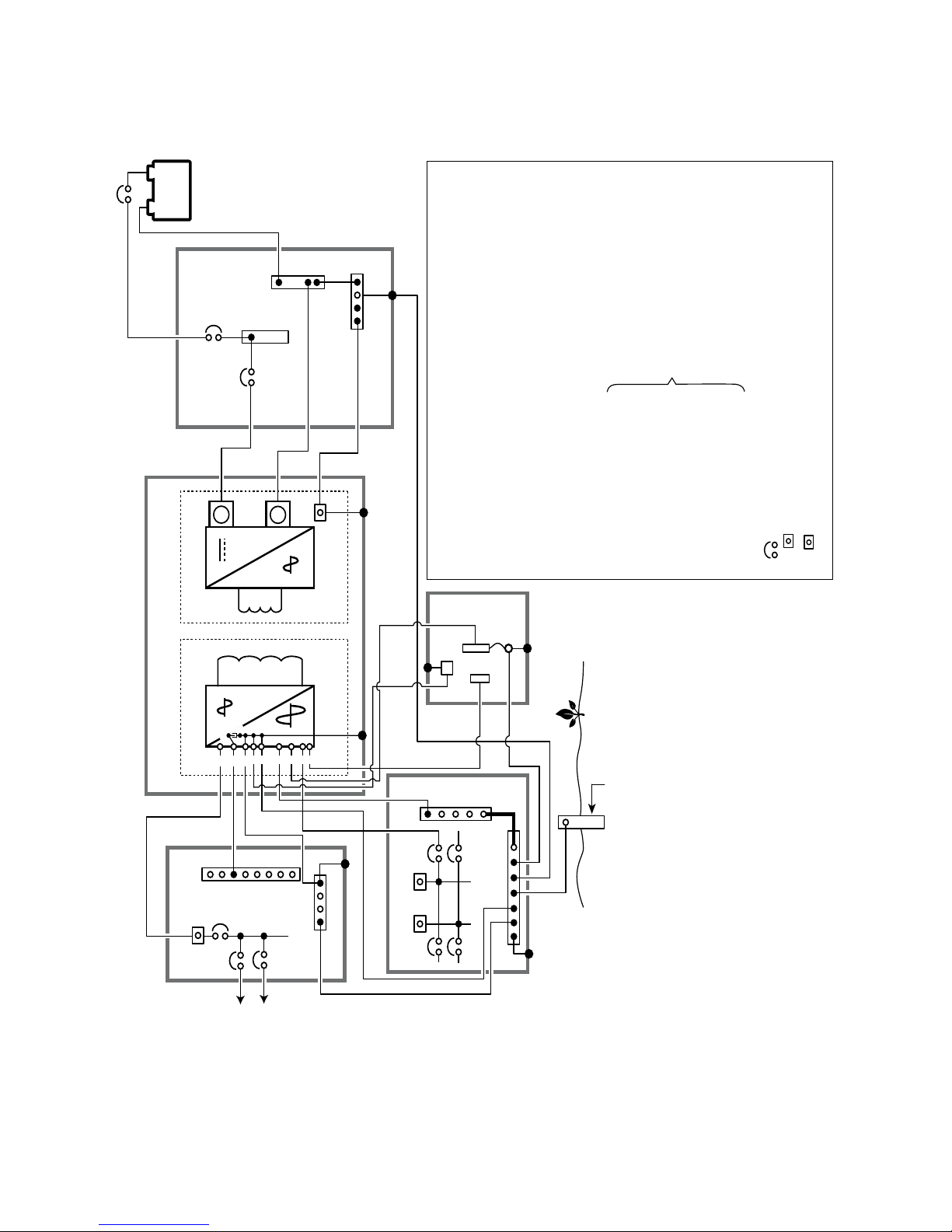
SECTION 3 | Installation
+
-
+
-
NOTES:
1: Please ensure that Neutral of the Generator is bonded to the frame / chassis internally.
If not, bond the Neutral terminal to the Earth Terminal “E” externally.
586
749
101211
13
Grounding Electrode (GE)
i.e. the Ground Rod embedded
in earth.
ELECTRICAL
SUB-PANEL FOR
EVO (SINGLE
PHASE: 120 VAC)
GRID ELECTRICAL PANEL
(SPLIT PHASE: 120/240 VAC)
D.C. ELECTRICAL
PANEL
N-B
G-B
G1
G2
N-B
G-B
G-B
A B
A.C. Section D.C. Section
Neg. (-)
Bus
Lead Acid
Battery Bank
Pos. (+)
Bus
EVO INVERTER CHARGER
To loads
backed up
by EVO
B
L.
N.
G.
E.
N-G.
N-B.
G-B.
G1.
SBJ.
G2.
GE.
4.5.6.7.8.
9.
10.
11.
12.
13.
Line terminal of generator output
Neutral terminal of generator output
Ground terminal of generator output
Earth terminal of generator (Bonded to the frame / chasis of the generator)
Neutral to Ground Bond
Neutral Bus Bar
Grounding Bus Bar
AC Input and AC Output Grounding terminals in EVO
(Are internally bonded to the metal frame / chassis of the unit)
System Bonding Jumper
DC side Grounding Terminal on EVO (5, Fig 3.8)
Grounding Electrode (Ground Rod)
GRID LINE
GRID GND
GRID NEUTRAL
GENERATOR LINE
GENERATOR GND
GENERATOR NEUTRAL
OUTPUT LINE
OUTPUT GROUND
OUTPUT NEUTRAL
Quick Disconnect
Circuit breaker
120 VAC Leg, Phase A
120 VAC Leg, Phase B
(180º out of phase with Phase A Leg)
SBJ
LINE
GE
A
Refer to AC
Input/Output
Connectors
at Fig 3.9
G
L
E
N-G
N
Generator
(See Note 1)
AWG #6
AWG #6
Fig 3.12 Grounding Arrangement - EVO Series
Page 56
56 | SAMLEX AMERICA INC.
SECTION 3 | Installation
3.15 SHORE BASED INSTALLATION
3.15.1 Typical Shore Based Installation
Fig. 3.13 illustrates a typical shore based installation
Battery is connected to the DC input connections through DC Electrical Panel with an ap-
propriate fuse to protect the DC input cables against short circuit
Battery Temperature Sensor Model EVO-BCTS is installed on the Positive or Negative post
of the battery and connected to the port for the Temperature Sensor
Supplementary battery charging is being carried out through a solar array and a Charge
Controller connected to the DC input provided for external battery charger
AC input to the EVO is fed from the Grid and Generator Panel
AC output from the EVO is fed to the AC Electrical Sub-Panel for EVO
Automatic Generator start/stop is possible. Please see Section 4.7 for details
!
CAUTION!
When using generator, please ensure the following:
• Neutral of the generator is bonded to the chassis of the generator and the chassis is
bonded to the Earth Ground (Ground Rod "GE").
• If the Generator is a 120VAC / 240VAC Split Single Phase with 120 VAC phase fed to
the EVO, then both 120VAC Split Phases of the generator should be equally loaded
(balanced) to prevent deterioration of regulation of generator's output voltage. Poor
regulation of generator output voltage may lead to interruption of charging in the EVO.
!
ATTENTION!
Lorsque vous utilisez le générateur, vériez les points suivants :
• Neutre du générateur est collée sur le châssis de l'alternateur et le châssis est collé à la terre (masse tige "GE").
• Si le générateur est a 120VCA / 240VCA Phase unique fendue avec phase 120VCA nourri à l'EVO, puis les deux
120VCA Split Phases du générateur devrait être également chargé (équilibré) pour prévenir la détérioration du
règlement de tension de sortie du générateur. Une mauvaise régulation de tension de sortie du générateur peut
entraîner l'interruption de la charge à l'EVO.
Page 57
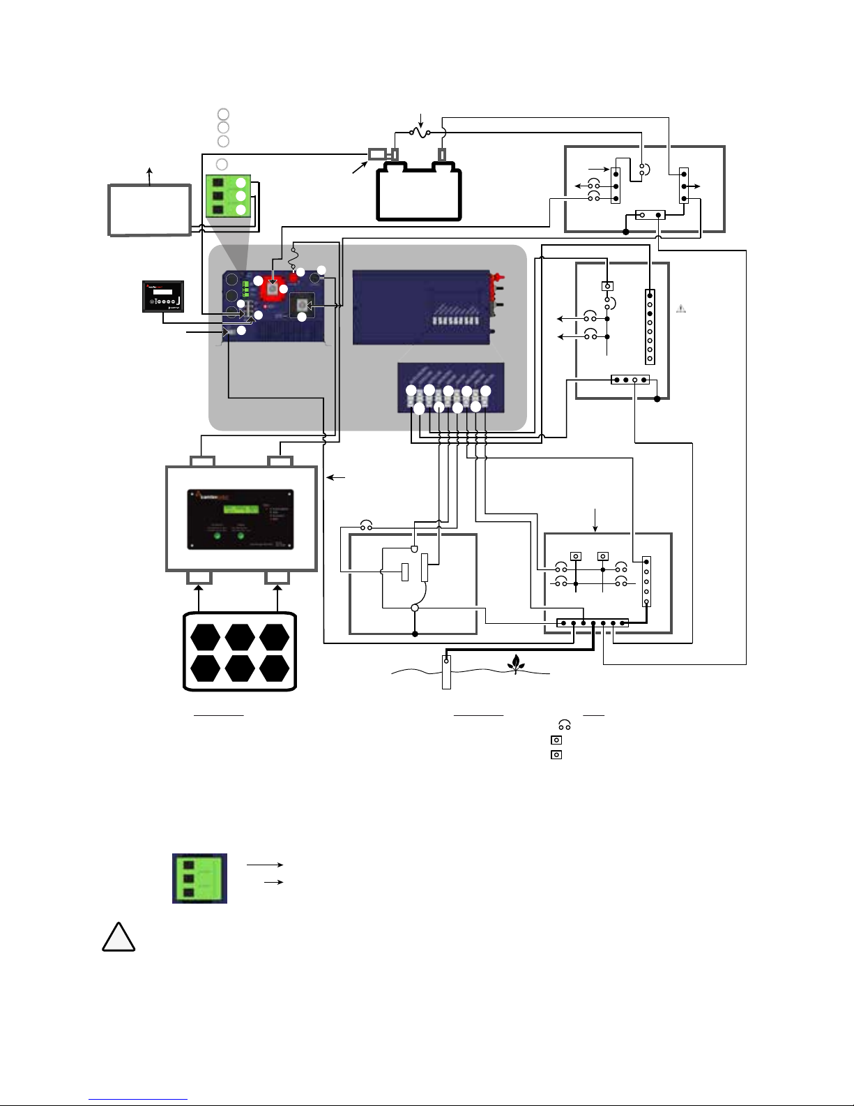
SECTION 3 | Installation
Optional
Generator Auto
Start/Stop Control
Module
BATTERY
TEMPERATURE
SENSOR MODEL
EVO-BCTS
+
-
LEAD ACID
BATTERY BANK
NO - Normally Open Contact
Common
NC - Normally Closed Contact
BATTERY SIDE FUSE (Within 7” of Positive Post)
EVO INVERTER
CHARGER
Ground
Terminal (5)
External
Charge
Controller
Solar Panel(s)
Battery -
Battery +
PV -
PV +
Fuse
G-B
N-B
ELECTRICAL
SUB- PANEL
FOR EVO
( CAUTION!
Use 120 VAC
Single Phase
Panel and NOT
120/240VA
Split Phase
Panel)
N
To
Loads
Optional
Remote Control
EVO-RC
Ground Rod embedded in earth.
GE
N
PANEL
GENERATOR
G-B
A B
NG
N-B
SERVICE
PANEL
AC SIDE
(See Fig 2.3)
G
NG
FRONT
(See Fig 2.1)
1.
2.
3.
4.
5.
6.
7.
14.
4.
5.
6.
7.
8.
9.
10.
11.
12.
AC SIDE OF EVO
GRID LINE
GRID GND
GRID NEUTRAL
GEN LINE
GEN GND
GEN NEUTRAL
OUTPUT LINE
OUTPUT GND
OUTPUT NEUTRAL
A
B
N-B
NG
G-B
GE
E
N
L
G
OTHER
Circuit breaker
120 VAC Leg A
120 VAC Leg B
(Legs A&B are split phases)
Neutral Bus Bar
Neutral to Ground Bond
Grounding Bus Bar
Grounding Electrode (Ground Rod)
Earth Connector on generator
(bonded to frame/chassis of the generator)
Neutral terminal of generator output
Line terminal of generator output
Grounding terminal of generator output
LINE
To Remote Start/Stop
Terminals on the
Generator
12
11
5
7
6
1
3
4
10
8
4
5
7
9
6
14
Status Relay
NO
Common
NC
To optional
Generator Auto
Start/Stop
Module
14
A
B
C
A
B
C
2
DC SIDE OF EVO
Battery Positive
Battery Negative
External Charger Positive
External Charger Negative
Grounding Terminal
RF-45 Jack for Temperature Sensor
RJ-45 Jack for Optional Remote Control EVO-RC
Status Relay Terminals for initiating automatic generator start/stop
GRID ELECTRICAL
PANEL (120/240VAC),
SPLIT PANEL
Minimum Wire
Size AWG #6
E
L
Pos (+)
Bus
Neg (-) Bus
G-B
DC ELECTRICAL
PANEL
Fig 3.13 Typical Shore Based Installation
!
CAUTION!
The Neutral Terminals of Grid and Generator Inputs are internally bonded to the metal chassis of EVO (The
Neutral Output Terminal of EVO is bonded to the metal chassis of EVO or kept isolated from the metal chassis
of EVO through Neutral to Chassis Ground bond Switching Relay; See Section 4.5.1). Hence, use PLAIN BREAKER
and NOT GFCI / GFCI protected breaker on the circuit feeding AC power from Grid / Generator to the EVO. If
GFCI / GFCI protected breaker is used on the Grid / Generator circuit feeding the EVO, the GFCI will trip due to
splitting of Neutral Return Currents.
Page 58
!
ATTENTION!
Les Bornes neutres de grille et entrées du générateur sont intérieurement collée au châssis métallique de EVO (la borne
de sortie neutre Evo est collée au châssis métallique de EVO ou gardé isolé du châssis métallique de EVO par le neutre à
la masse du châssis relais de commutation bond; voir section 4.5.1). Par conséquent, utiliser le format et le disjoncteur
pas le GFCI protégés disjoncteur GFCI / sur l'alimentation du circuit de l'alimentation CA de grille / générateur pour l'EVO.
Si le GFCI / le GFCI est utilisé sur disjoncteur protégé la grille / circuit générateur alimentant les EVO, le GFCI se déclenche
en raison de fractionnement des courants de retour au neutre.
3.16 MOBILE INSTALLATION - GENERAL INFORMATION
3.16.1 GFCI Protection for Vehicle Application
When this unit is installed in vehicles, it is to be ensured that Ground Fault Circuit Interrupter(s)
[GFCI] are installed in the vehicle wiring system to protect all branch circuits.
WARNING!
Please ensure that Ground Fault Circuit Interrupter(s) [GFCI] are installed in the vehicle wiring
system to protect all branch circuits.
GFCIs listed in Table 1.5 have been tested to operate satisfactorily and are acceptable.
ATTENTION!
Veuillez assurer que le(s) disjoncteur(s) de terre [GFCI] est/sont installé dans le système de câblage du véhicule pour
protèger tous les circuits de dérivation.
Des disjoncteurs de terre ci-dessous ont été testé. Leur fonctionnement est acceptable, Table 1.5.
3.16.2 Requirement of Deep Cycle, Auxiliary Battery and Battery Isolator for
Powering Inverters in Mobile Installations
Ba
sic information on Lead Acid Batteries is given in Section 1.4 under "General
Information - Lead Acid batteries".
An RV / vehicle has Starter, Lighting and Ignition (SLI) battery. As explained in White Paper titled
“Batteries, Chargers and Alternators”, SLI batteries are designed to produce high power in
short bursts for cranking.
SLI batteries use lots of thin plates to maximize the surface area of the plates for providing very
large bursts of current (also specified as Cranking Amps). This allows very high starting current
but causes the plates to warp when the battery is cycled. Vehicle starting typically discharges
1%–3% of a healthy SLI battery’s capacity. The automotive SLI battery is not designed for
repeated deep discharge where up to 80% of the battery capacity is discharged and then
recharged. If an SLI battery is used for this type of deep discharge application, its useful service
life will be drastically reduced. Hence, this type of battery is not recommended for the storage
of energy for inverter applications. A second deep cycle auxiliary battery must be installed in
the RV for powering the EVO (Deep cycle, auxiliary battery is shown in Figs. 3.14a and 3.14b).
58 | SAMLEX AMERICA INC.
SECTION 3 | Installation
Page 59

When the second auxiliary deep cycle battery is used, a Battery Isolator is required that will allow parallel connection of the two batteries for charging when the alternator is ON and disconnecting the parallel connection when the alternator is stopped (Isolator is shown in Figs. 3.14a
and 3.14b). The capacity of the Battery Isolator should be as follows:
• For EVO-2012: The maximum continuous DC current required is 266A. The capacity of
the Battery Isolator should be more than 266A or more than the capacity of the alternator,
whichever is higher
• For EVO-2224: The maximum continuous DC current required is 133A. The capacity of
the Battery Isolator should be more than 133A or more than the capacity of the alternator,
whichever is higher
• For EVO-3012: The maximum continuous DC current required is 373A. The capacity of
the Battery Isolator should be more than 373A or more than the capacity of the alternator,
whichever is higher
• For EVO-4024: The maximum continuous DC current required is 266A. The capacity of
the Battery Isolator should be more than 266A or more than the capacity of the alternator,
whichever is higher
3.16.3 Requirement to Keep the Neutral Conductor of Shore Power Isolated
From the Chassis Ground of the RV
As explained in on-line White
Paper titled “Grounded Electrical Power Distribution
System”, in the RV, the Neutral Bus Bar is NOT bonded to the Chassis of the RV. In the RV,
the Neutral is floating with respect to the chassis of the RV. This is necessary for safety
because if the Neutral was bonded to the chassis of the RV and if the Neutral and the Hot got
reversed by mistake, the chassis of the RV will be at 120 VAC with respect to the Earth
Ground. If a person standing on the Earth Ground touches the chassis of the RV, he will be
fed with 120 VAC and will receive electrical shock!
3.16.4 Typical Mobile Installation
Fig 3.14A illustrates typical RV installation using 30A, 120VAC, Single Phase Service Inlet and
Fig 3.14B illustrates typical RV installation using 50A, 120/240VAC Split Phase Service Inlet:
Auxiliary Battery is connected to the DC input connections through an appropriate fuse
to protect the DC input cables against short circuit
Auxiliary battery will be charged by the alternator through the Battery Isolator
Battery Temperature Sensor Model BTS-EVO is installed on the Positive or Negative post
of the auxiliary battery and connected to the port for the Temperature Sensor
Supplementary battery charging is being carried out through a solar array and a
Charge Controller connected to the DC input provided for external battery charger
AC input to the EVO is fed from the Electrical Panel of the RV (through suitable
breaker) and from the generator (through suitable breaker).
If the RV has a 50A Service, 120VAC Single Phase input to the EVO can be fed from
either of the 2 Split Phase Legs of the 50A RV Panel (through suitable breaker).
AC output from the EVO is fed to the Electrical Sub-Panel for EVO (Use 120V version
and NOT 120/240 Split Phase version of the Electrical Sub-panel)
Automatic Generator start/stop is possible. Please see Section 4.7 for details.
SECTION 3 | Installation
Page 60
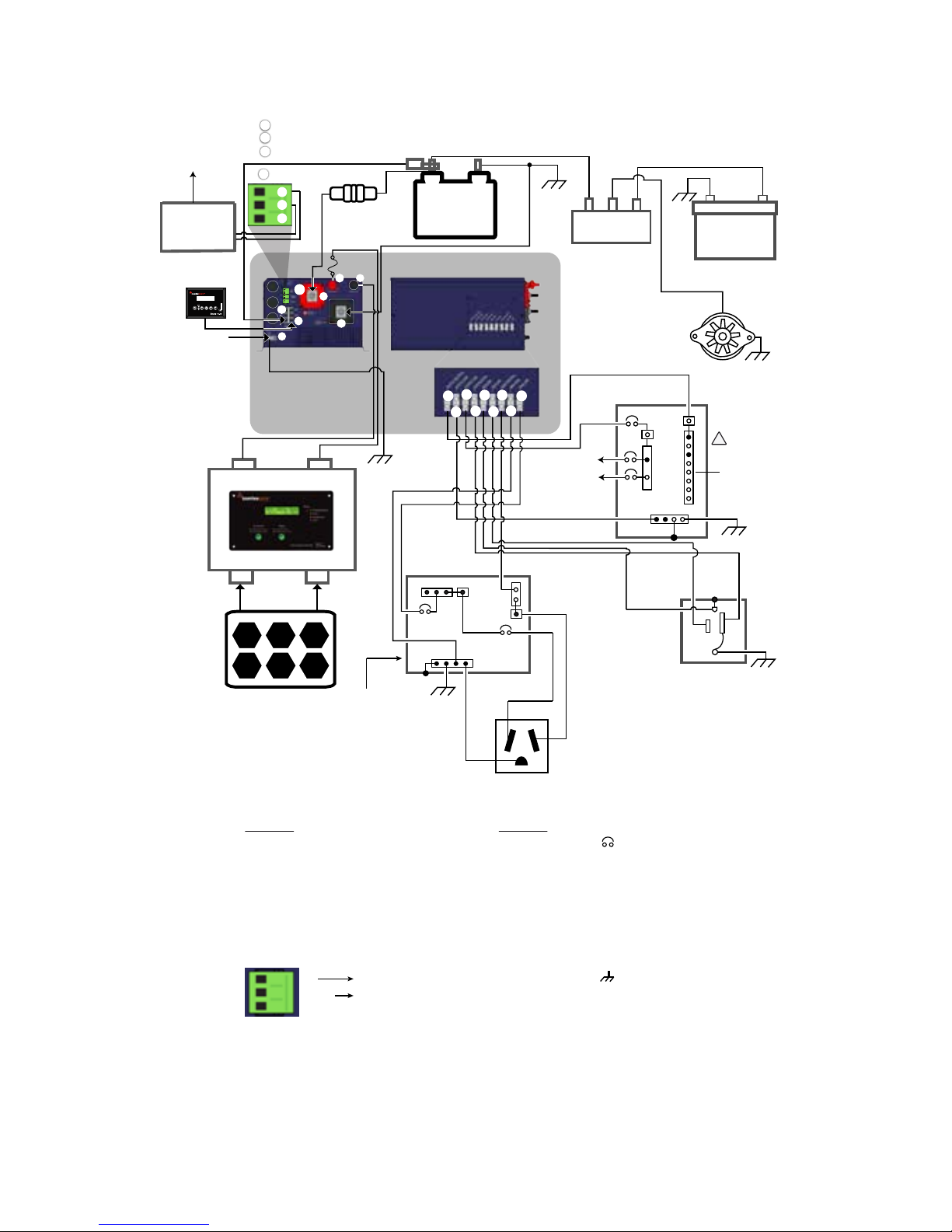
60 | SAMLEX AMERICA INC.
SECTION 3 | Installation
Fig 3.14A Typical Mobile Installation Using 30A, 120 VAC, Single Phase RV Service Inlet
+
-
Lead Acid
Auxiliary
Battery Bank
Battery
Temperature
Sensor
- Model EVO-BCTS
+ + +
Battery Isolator
Alternator
Engine Starting
Battery
- +
EVO INVERTER
CHARGER
Grounding
Terminal (5)
External
Charge
Controller
Solar Panel(s)
Battery -
Battery +
PV -
PV +
Fuse
G-B
G
120, SINGLE PHASE
ELECTRICAL SUB-PANEL
FOR EVO
N
N-B
G-B
L-B L
120V, SINGLE
PHASE ELECTRICAL
PANEL OF RV
30A Service Inlet for 30A
RV Power Supply Cord
NEMA TT-30P
Optional Remote
Control EVO-RC
To Remote Start/Stop
Terminals on the
Generator
Optional
Generator Auto
Start/Stop
Control Module
1.
2.
3.
4.
5.
6.
7.
14.
DC SIDE OF EVO
Battery Positive
Battery Negative
External Charger Positive
External Charger Negative
Grounding Terminal
RJ-45 Jack for Temperature Sensor
RJ-45 Jack for Optional Remote Control EVO-RC
Status Relay Terminals for initiating automatic generator start/stop
4.
5.
6.
7.
8.
9.
10.
11.
12.
AC SIDE OF EVO
GRID LINE
GRID GND
GRID NEUTRAL
GEN LINE
GEN GND
GEN NEUTRAL
OUTPUT LINE
OUTPUT GND
OUTPUT NEUTRAL
N-B
L-B
G-B
L
N
G
EG
NG
OTHER
Circuit breaker
Neutral Bus Bar
Line Bus Bar
Ground Bus Bar
Line terminal
Neutral terminal
Ground terminal
Earthing terminalon the generator
(bonded to frame/chassis of generator)
Neutral to Ground bond
RV Chassis Ground
Do Not use 120V /
240V Panel Board
FRONT
(See Fig 2.1)
AC SIDE
(See Fig 2.3)
5
7
6
14
1
3
4
12
11
10
8
6
4
9
7
5
!
Status Relay
NO
Common
NC
To optional
Generator Auto
Start/Stop
Module
Fuse
(Within 7”
of battery
terminal)
NO - Normally Open Contact
Common
NC - Normally Closed Contact
14
A
B
C
B
A
C
2
L
L-B
To loads
backed up
by EVO
G
NL
N-B
N
N
L
N-G
Generator
Page 61
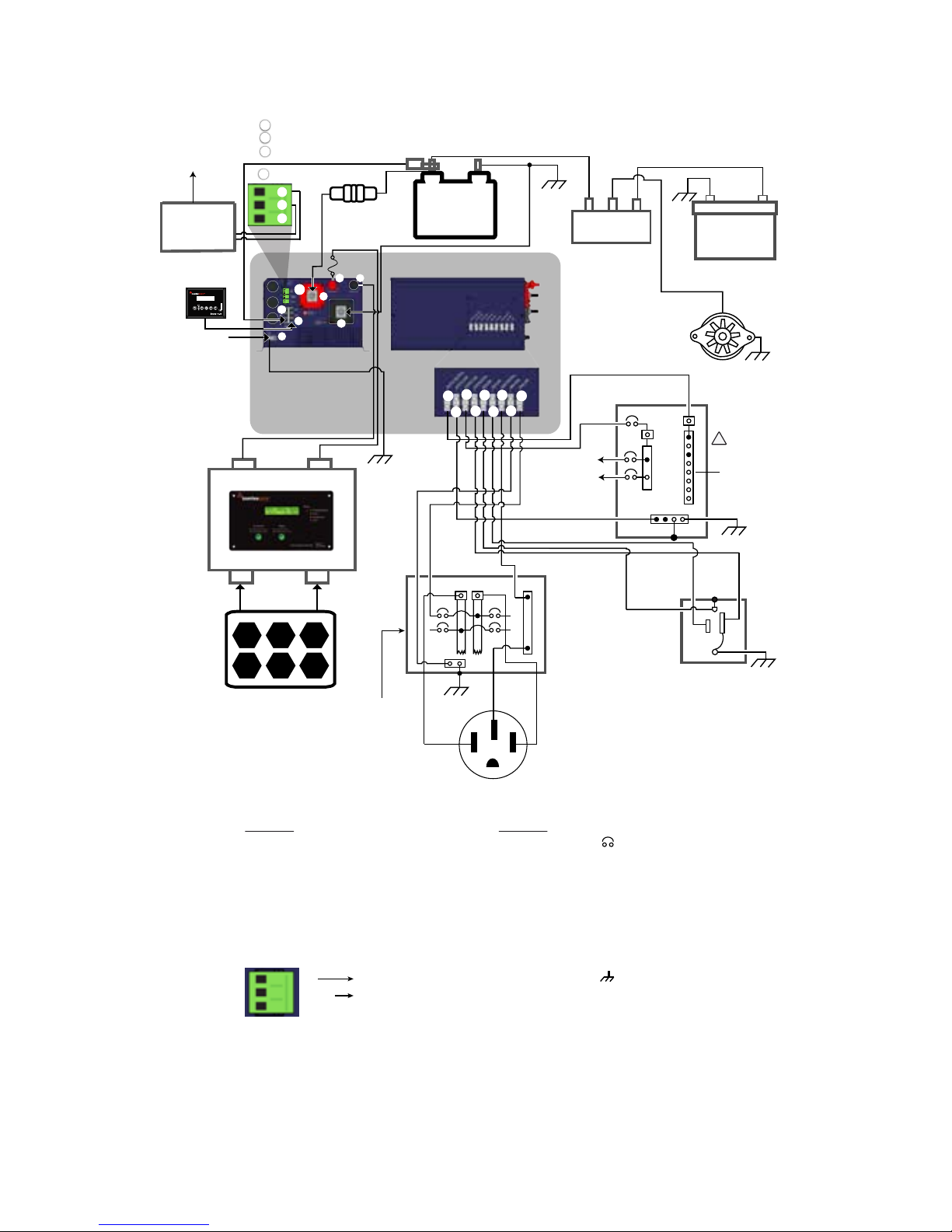
SECTION 3 | Installation
Fig 3.14B Typical Mobile Installation Using 50A, 120/240 VAC Split Phase RV Service Inlet
+
-
Lead Acid
Battery Bank
Battery
Temperature
Sensor
- Model EVO-BCTS
+ + +
Battery Isolator
Alternator
Engine Starting
Battery
- +
EVO INVERTER
CHARGER
Grounding
Terminal (5)
External
Charge
Controller
Solar Panel(s)
Battery -
Battery +
PV -
PV +
Fuse
G-B
G
120, SINGLE PHASE
ELECTRICAL SUB-PANEL
FOR EVO
N
N-B
RV ELECTRICAL
PANEL BOARD
50A, 120/240VAC
SPLIT PHASE
50A RV INLET NEMA14-50R
120/240V, SPLIT PHASE
Optional Remote
Control EVO-RC
To Remote Start/Stop
Terminals on the
Generator
Optional
Generator Auto
Start/Stop
Control Module
1.
2.
3.
4.
5.
6.
7.
14.
DC SIDE OF EVO
Battery Positive
Battery Negative
External Charger Positive
External Charger Negative
Grounding Terminal
RJ-45 Jack for Temperature Sensor
RJ-45 Jack for Optional Remote Control EVO-RC
Status Relay Terminals for initiating automatic generator start/stop
4.
5.
6.
7.
8.
9.
10.
11.
12.
AC SIDE OF EVO
GRID LINE
GRID GND
GRID NEUTRAL
GEN LINE
GEN GND
GEN NEUTRAL
OUTPUT LINE
OUTPUT GND
OUTPUT NEUTRAL
N-B
L-B
G-B
L
N
G
EG
NG
OTHER
Circuit breaker
Neutral Bus Bar
Line Bus Bar
Ground Bus Bar
Line terminal
Neutral terminal
Ground terminal
Earthing terminalon the generator
(bonded to frame/chassis of generator)
Neutral to Ground bond
RV Chassis Ground
Do Not use 120V /
240V Panel Board
FRONT
(See Fig 2.1)
AC SIDE
(See Fig 2.3)
5
7
6
14
1
3
4
12
11
10
8
6
4
9
7
5
!
Status Relay
NO
Common
NC
To optional
Generator Auto
Start/Stop
Module
Fuse
(Within 7”
of battery
terminal)
NO - Normally Open Contact
Common
NC - Normally Closed Contact
14
A
B
C
B
A
C
2
L
L-B
To loads
backed up
by EVO
G
N
X Y
To loads
backed up
by EVO
N-B
N
L
N-G
Generator
B
A
GB
BA
B
A
Auxiliary
Page 62

62 | SAMLEX AMERICA INC.
4.1 GENERAL DESCRIPTION
EVO is a Pure Sine Wave, Bi-directional, Single-Phase Inverter / Charger with a Transfer Relay that
operates either as an inverter OR as a smart battery charger. It uses a common Converter Section
that can work in two directions – in one direction it converts external AC power to DC power
to charge the batteries using Grid or Generator (Charging Mode) and in the other direction, it
converts DC power from the battery to AC power (Inverting Mode). This allows the same power
components to be used in both directions resulting in high-energy transfer efciency with fewer
components. Please note that it can NOT work in both the directions at the same time (i.e. it cannot work as an inverter and as a charger at the same time).
High performance 100 MHz DSP (Digital Signal Processing) type of micro-controller and Pulse
Width Modulated (PWM) conversion circuits are used for the above implementation.
4.2 COMPONENTS OF THE SYSTEM
It consists of 3 Sections – Inverter Section, Battery Charger Section and AC Input/Transfer Relay
Section. The unit is fed with the following inputs:
Up to 2 external AC input power sources – Grid or Generator or both with PRIORITY for Grid
if both Grid and Generator inputs are available at the same time
DC Battery Source consisting of 12V/24V battery bank. - 4 versions of EVO are available. 2
versions for 12 VDC battery input (EVO-2212 and EVO-3012) & 2 for 24 VDC battery input
(EVO-2224 and EVO-4024)
Additional external charging source like Solar Charge Controller / AC charger of up to 50A
capacity. The output of the external charging source is routed through this unit and operates
in parallel with the internal charger. The internal charging current is controlled to ensure that
the combined current fed to the battery does not exceed the programmed Bulk Charging
Current. This improves the life of the battery.
4.3 INVERTER SECTION
The Inverter Section is a heavy-duty, continuous rated, DSP micro-controller based inverter generating a Pure Sine Wave output of 120 VAC, 60 Hz / 50 Hz (60 Hz default) from the DC Battery
Source. It is able to supply AC power to various types of AC loads such as resistive loads (heaters,
incandescent lamps etc) or reactive loads (motors, air conditioners, refrigerators, vacuum cleaners, fans, pumps, Switched Mode Power Supplies (SMPS) used in audio / video equipment and
computers, etc.).
4.3.1 Principle of working of Inverter Section
The low DC voltage from the DC Battery Source is inverted to the AC voltage in two steps. The low
DC voltage from the DC Battery Source is rst converted to low frequency (60 Hz or 50 Hz), low
voltage synthesized sine wave AC using an H-bridge conguration and high frequency PWM (Pulse
Width Modulation) technique. The low frequency, low voltage synthesized sine wave is then stepped
up to 120 VAC pure sine wave voltage using a low frequency Isolation Transformer and ltration
circuit. This type of DC to AC inversion is called Hybrid Type – a combination of low frequency and
high frequency implementation. Other distinctive features of the Inverter Section are given below:
Soft Start: The inverter design incorporates “Soft Start” feature with the following advantages and protections:
SECTION 4 | General Description & Principles of Operations
Page 63

- When the unit powers up, it starts in Inverting Mode rst. The output voltage ramps up
gradually from around 48 VAC to 120 VAC in around 200 ms. This reduces otherwise very
high starting inrush current drawn by AC loads like Switched Mode Power Supplies (SMPS)
and motor driven loads like fans, pumps, compressors etc. This will result in lower motor
inrush current (which typically can be up to 650% of the full load current of the motor),
which means lesser mechanical stresses, wear and tear and increased lifetime of the motor,
coupling and fan. Additionally, the impact on the load side components is greatly reduced,
meaning less likelihood of causing problematic voltage drops during starting.
Power Surge – Up to 300%:
- The inverter is able to deliver very high surge power / current of up to 300% for 1 ms followed
by 200% for 100 ms. This range of high instantaneous power is delivered at the rated voltage
and hence, it is able to provide very high starting torque for difcult motor driven loads like
compressors and pumps that require higher Locked Rotor Current during startup.
- If the power drawn by the load exceeds the above surge ratings, the inverter protects
itself by limiting the load current to 300% / 200% which results in reduction of
output voltage and consequent reduction in load current. The output voltage recovers
automatically when power drawn by the load drops below the above surge limits
Power Boost up to 150%: Higher percentage of rated power can be provided for limited
time periods as follows:
• 150% for 5 sec
• 140% for 30 sec
• 120% for 5 min
• 110% for 30 min
4.4 DIRECT DUAL AC INPUT ARCHITECTURE
For higher reliability and redundancy, direct AC input from Grid and Generator can be fed
simultaneously to separate AC Input Circuits. Only one AC source is selected at one time. When
both Grid and Generator are available simultaneously, Grid is given priority. Transfer from Grid
to Generator or from Generator to Grid is always routed through the inverter. Please see details
under “Synchronized Transfer of Power”.
4.5 TRANSFER RELAY SECTION
Transfer Relay Section is used to either feed AC power to the Battery Charger Section and at
the same time, pass through the AC power from the external AC input power source to the
load (As long as the external AC input power from Grid/Generator is available and is within the
programmed limits of voltage and frequency) or to transfer the load to the Inverter Section (In
case of loss of the external AC input power source or if this source is not within the programmed
limits of voltage and frequency). Typical transfer time is 16 milliseconds from Grid/Generator to
Inverter and <1ms from Inverter to Grid/Generator. Heavy duty 70A (2x35A in parallel), Transfer
Relay is used for reliable transfer of up to 300% surge power and for Neutral to Ground Bond
Switching (40A rated for EVO-2212 and EVO-2224).
4.5.1 AC Transfer and Output Neutral To Chassis Ground Bond Switching
As required by NEC and UL Standard 458, automatic switching of bonding between the Ouput Neutral and Chassis Ground has been provided in EVO through “Output Neutral to Chassis
Ground Bond Switching Relay” [K4 in Figs 4.1(a) and 4.1(b)]. Switching is bonding as follows:
SECTION 4 | General Description & Principles of Operations
Page 64
64 | SAMLEX AMERICA INC.
• Whenoperatingasaninverter,thecurrentcarryingconductoroftheInverterSectionthatis
connected to the Output Neutral terminal of EVO is bonded to the metal chassis of EVO by the
“Output Neutral to Chassis Ground Bond Switching Relay” [K4 in Figs 4.1(a) and 4.1(b)]. As the
metal chassis of EVO is in turn bonded to the Earth Ground (in shore installations) or to the RV
Ground (chassis of the RV) or to the Boat Ground (DC Negative Grounding Bus Bar and the Main
AC Grounding Bus Bar are tied together in a boat and this is called the “Boat Ground”), this current carrying conductor of the Inverter Section (connected to the output terminal) will become
the Grounded Conductor (GC) or the Neutral of the Inverter Section.
• WheninChargingMode,theNeutralconductoroftheGridpower/Generatorwillbeconnected to the Output Neutral terminal of EVO. At the same time, the “Output Neutral to
Chassis Ground Bond Switching Relay” [K4 in Figs 4.1(a) and 4.1(b)] will unbond (disconnect) the Output Neutral connector of EVO from the metal chassis of EVO. This will ensure
that the Grounded Conductor (GC) i.e. the Neutral of the Grid power/Generator is bonded
to the Earth Ground at one single point at the location of the AC Power Distribution System
of the Marina/RV Park/Shore Power.
• Disabling Neutral to Ground Bond: In some applications, the Output Neutral of EVO
may be required to remain isolated from the chassis/Ground at all times. For this, automatic
Output Neutral to Ground bond can be disabled by disconnecting the Male/Female Quick
Disconnect located in the AC wiring compartment. [Please see (i) 13, Fig 3.9 and (ii) "QD' in
Figs 4.1(a) and 4.1(b)]
- “Neutral to Ground Switching in RV and Marine Applications”
!
CAUTION!
The Neutral Terminals of Grid and Generator Inputs are internally bonded to the metal chassis of
EVO (The Neutral Output Terminal of EVO is bonded to the metal chassis of EVO or kept isolated
from the metal chassis of EVO through Neutral to Chassis Ground bond Switching Relay; See Section
4.5.1). Hence, use PLAIN BREAKER and NOT GFCI / GFCI protected breaker on the circuit feeding
AC power from Grid / Generator to the EVO. If GFCI / GFCI protected breaker is used on the Grid /
Generator circuit feeding the EVO, the GFCI will trip due to splitting of Neutral Return Currents.
!
ATTENTION!
Les bornes neutre de l’entrée du réseau et du générateur sont liés à l'interne au châssis métallique de l’EVO (la borne
neutre de la sortie de l'EVO est lié au châssis métallique de l’EVO ou est maintenus isolés du châssis métallique de l’EVO
a travers du lien neutre à châssis du relais de commutation; Voir la section 4,5,1). Par conséquent, utiliser « PLAIN
BREAKER » et non « GFCI / GFCI PROTECTED BREAKER» sur le circuit d'alimentation CA du réseau / générateur à l'EVO.
Si le disjoncteur protégé GFCI / GFCI est utilisé sur le circuit de réseau / générateur alimentant l’EVO, le disjoncteur se
déclenchera en raison de fractionnement des courants de retour au neutre.
SECTION 4 | General Description & Principles of Operations
Page 65

4.5.2 Operation of Transfer Relay and Output Neutral to Chassis Ground
Bond Switching Relay – EVO-2212 and EVO-2224
Refer to Schematic at Fig 4.1(a)
The Bi-directional Transformer is used as follows:
o Feeds AC output from the Inverter Section when Grid / Generator power is not available.
o Feeds Grid / Generator power to the Battery Charger Section when Grid / Generator are
available.
Switching of Hot Output (OUTPUT LINE)
o 40A rated SPDT Relays K2 and K3 are used to switch the Hot Output Connector
(OUTPUT LINE) to either the Inverter Section or to Grid / Generator
o When Grid / Generator Power is available, relays K2 or K3 will be energized and contact
4 switches over to contact 5 (Grid has PRIORITY over Generator if both are present
simultaneously). The Bidirectional Transformer works as a battery Charger. The Hot AC
input from the Grid (GRID LINE) or from the Generator (GEN LINE) is fed to the Hot input
of the Bi-directional Transformer for battery charging and at the same time, it is passed
through to the Hot Out (OUTPUT LINE) for powering the AC loads
o When Grid / Generator power fails, relays K2 / K3 will be de-energized and contact 4
switches back to contact 3. Output from the Inverter Section is fed to the Bi-directional
Transformer and onwards to the Hot Out (OUTPUT LINE) for powering the AC loads
Switching of Bonding of Output Neutral to Chassis Ground
o 40A rated SPDT Relay K4 is used to switch the bonding of the Output Neutral Connector
(OUTPUT NEUTRAL) to the chassis of the unit
o When Grid / Generator Power is available, relay K4 will be energized and contact 4
switches over to contact 5. Neutral input from the Grid (GRID NEUTRAL) or from the
Generator (GEN NEUTRAL) is fed to the Neutral input of the Bi-directional Transformer
for battery charging and at the same time, it is passed through to the Output Neutral
(OUTPUT NEUTRAL) for powering the AC loads. Please note that in this condition, the
Output Neutral (OUTPUT NEUTRAL) is isolated from the chassis of the unit
o When Grid / Generator power fails, relay K4 will be de-energized and contact 4 switches
back to contact 3. Neutral output from the Inverter Section is fed the Neutral of the
Bi-directional Transformer and onwards to the output Neutral (OUTPUT NEUTRAL) for
powering the AC loads. At the same time, the output Neutral (OUTPUT NEUTRAL) gets
bonded to the metal chassis of the unit through the mated contacts of the Insulated
Quick Disconnect "QD" located in the AC Wiring Compartment (13, Fig 3.9)
4.5.3 Operation of Transfer Relays and Output Neutral to Chassis Ground
Bond Switching Relay – EVO-3012 and EVO-4024
Refer to Schematic at Fig 4.1(b)
The Bi-directional Transformer is used as follows:
o Feeds AC output from the Inverter Section when Grid / Generator power is not available.
o Feeds Grid / Generator power to the Battery Charger Section when Grid / Utility are available.
SECTION 4 | General Description & Principles of Operations
Page 66
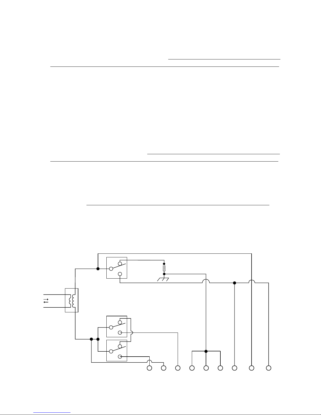
66 | SAMLEX AMERICA INC.
Switching of Hot Output (OUTPUT LINE)
o 70A rated DPDT Relays K2 and K3 are used to switch the Hot Output Connector (OUTPUT LINE) to
either the Inverter Section or to the Grid / Generator. Please note that in this relay, each of the 2 poles is
rated for 35A. The 2 poles are used in parallel to increase the contact current carrying capacity to 70A
o When Grid / Generator Power is available, relays K2 or K3 will be energized and contacts 7
and 9 will switch over to contacts 4 and 6 respectively (Grid has PRIORITY over Generator if
both are present simultaneously). The Bidirectional Transformer works as a battery Charger.
The Hot AC input from the Grid (GRID LINE) or from the Generator (GEN LINE) is fed to the
Hot input of the Bi-directional Transformer for battery charging and at the same time, it is
passed through to the Hot Out (OUTPUT LINE) for powering the AC loads
o When Grid / Generator power fails, relays K2 / K3 will be de-energized and contacts 7 and 9 will
switch back to contacts 1 and 3 respectively. Output from the Inverter Section is fed to the Bidirectional Transformer and onwards to the Hot Out (OUTPUT LINE) for powering the AC loads
Switching of Bonding of Output Neutral to Chassis Ground Bonding
o 70A rated DPDT Relay K4 is used to switch the bonding of the Output Neutral Connector (OUT-
PUT NEUTRAL) to the chassis of the unit. Please note that in this relay, each of the 2 poles is rated
for 35A. The 2 poles are used in parallel to increase the contact current carrying capacity to 70A
o When Grid / Generator Power is available, relay K4 will be energized and contacts 7 and 9
will switch over to contacts 4 and 6 respectively. Neutral input from the Grid (GRID NEUTRAL)
or from the Generator (GEN NEUTRAL) is fed to the Neutral input of the
Bi-directional Transformer for battery charging and at the same time, it is passed through to
the output Neutral (OUTPUT NEUTRAL) for powering the AC loads. Please note that in this
condition, the Output Neutral (OUTPUT NEUTRAL) is isolated from the chassis of the unit
o When Grid / Generator power fails, relay K4 will be de-energized and contacts 7 and 9 will
switch back to contacts 1 and 3 respectively. Neutral output from the Inverter Section is fed
the Neutral of the Bi-directional Transformer and onwards to the output Neutral (OUTPUT
NEUTRAL) for powering the AC loads. At the same time, the output Neutral (OUTPUT
NEUTRAL) gets bonded to the chassis of the unit through the mated contacts of the
Insulated Quick Disconnect "QD" located in the AC Wiring Compartment (13, Fig 3.9)
NEUTRAL
BI-DIRECTIONAL
TRANSFORMER
LINE
K4
K3
K2
METAL CHASSIS
GROUND OF THE EVO
3
4
5
3
4
5
3
4
5
INVERTING
CHARGING
OUTPUT
NEUTRAL
GRID
LINE
GRID
GND
GRID
NEUTRAL
GEN
LINE
GEN
GND
GEN
NEUTRAL
OUTPUT
LINE
OUTPUT
GND
QD
Fig 4.1(a) Operation of Transfer Relay and Neutral to Ground Bond Switching of EVO-2212 and EVO-2224
(See Legend on the next page 67)
SECTION 4 | General Description & Principles of Operations
Page 67
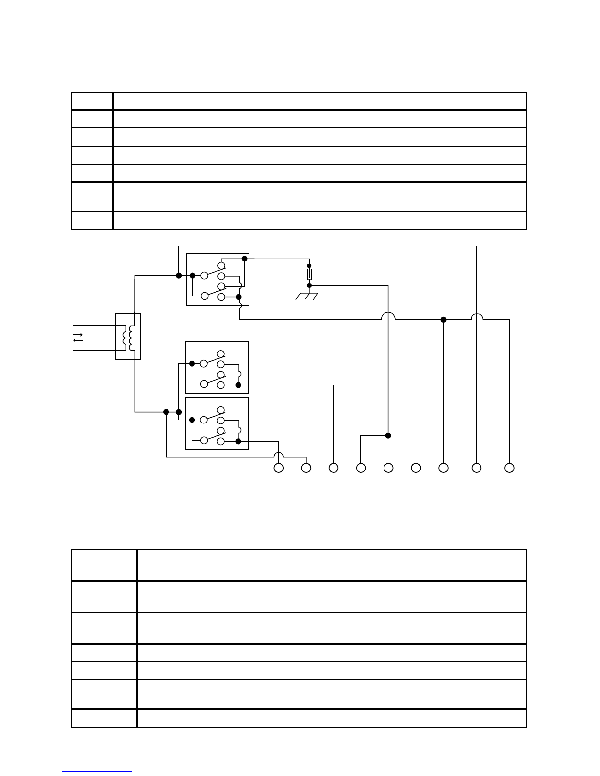
Legend for Fig 4.1(a)
K2 Transfer Relay (40A) for Grid, Line
K3 Transfer Relay (40A) for Generator, Line
K4 Relay (40A) for Neutral to Ground bond Switching
4, 3 Normally Closed Contacts
4, 5 Normally Open Contacts
QD
Quick Disconnect (13, Fig 3.9) for disconnecting Output Neutral to Chassis Ground bond in
Inverting Mode (Default - connected)
NOTE: Relays are de-energized in Inverting Mode and are energized in Charging Mode
NEUTRAL
BI-DIRECTIONAL
TRANSFORMER
LINE
K4
1
OUTPUT
NEUTRAL
GRID
LINE
GRID
GND
GRID
NEUTRAL
GEN
LINE
GEN
GND
GEN
NEUTRAL
AC OUTPUT
LINE
OUTPUT
GND
9
4
6
3
7
K2
1
9
4
6
3
7
K3
1
9
4
6
3
7
INVERTING
CHARGING
METAL CHASSIS
GROUND OF THE UNIT
QD
Fig 4.1(b) Operation of Transfer Relay and Neutral to Ground Bond Switching in EVO-3012 and EVO-4024
Legend for Fig 4.1(b)
K2 DPDT Transfer Relay (70A) for Grid, Line
Two 35A each poles are paralleled for 70A capacity
K3 DPDT Transfer Relay (70A) for Generator, Line
Two 35A each poles are paralleled for 70A capacity
K4 DPDT Transfer Relay (70A) for Neutral to Ground Bond Switching
Two 35A each poles are paralleled for 70A capacity
7,1 and 9,3 Normally Closed Contacts
7,4 and 9,6 Normally Open Contacts
QD
Quick Disconnect (13, Fig 3.9) for disconnecting Output Neutral to Chassis Ground
bond in Inverting Mode (Default - connected)
NOTE: Relays are de-energized in Invertering Mode and are energized in Charging Mode
SECTION 4 | General Description & Principles of Operations
Page 68

68 | SAMLEX AMERICA INC.
4.5.4 Synchronized Transfer of Power
Direct AC input from Grid and Generator can be fed simultaneously to separate AC Input
Circuits. Only one AC source is selected at one time. When both Grid and Generator are
available simultaneously, Grid has priority. To facilitate synchronization, transfer of power
from Grid to Generator or from Generator to Grid is always routed through the inverter.
4.5.5 Transfer From Inverter to Grid / Generator
When Grid / Generator becomes available, its voltage and frequency are checked if these
are within the programmed limits. If yes, the output voltage of the Inverter Section is
synchronized with Grid / Generator through Phase Locked Loop” (PLL). This synchronization
process takes few seconds. Once synchronization is completed, the load is transferred
instantly (within 1 ms) to Grid / Generator at Zero Crossing of the voltage waveform for
seamless transfer and for better protection of Transfer Relay contacts. The unit now operates
in “Charging Mode” with the AC power from the Grid / Generator charging the batteries as
well as providing power to the AC loads.
4.5.6 Transfer From Grid / Generator to Inverter
When the unit is operating in “Charging Mode” with the AC power from the Grid /
Generator charging the batteries as well as providing power to the AC loads, the phase and
frequency of Grid / Generator are tracked continuously. In case Grid / Generator fails or is
disconnected, the inverter will be forced into transfer at voltage which is at the same phase
and frequency at which Grid / Generator had been disconnected. Load will be transferred to
the inverter within 16ms at zero crossing. The unit will now work in “Inverting Mode” and
the batteries will start discharging.
4.5.7 Transfer Between Grid and Generator
As discussed in “Transfer from Inverter to Grid/Generator” above, the EVO prioritizes the Grid
over the Generator input. If the EVO is operating with the Generator input active and the
Grid input is restored, the EVO will transfer the load to its Inverter Section, and then transfer
back to the Grid input. Both operations are synchronized and the transfer is at the zero
crossing for a seamless transfer.
4.6 BATTERY CHARGER SECTION
The Battery Charger Section of these units is a powerful, 3/4 Stage, fully automatic battery
charging circuit. The same Isolation Transformer and the H-Bridge conguration are used to work
in the reverse direction, ie. rectify the AC voltage from the Primary AC Power Source to PWM
controlled low voltage DC to charge the DC Battery Source. That is why it is called a Bi-directional
device. Normal 3-Stage Charging Mode consists of Bulk, Absorption and Float stages (Default).
4-Stage Equalization Mode consists of Bulk, Absorption, Equalization and Float. (The Equalization
Mode is selectable). Equalization Mode is desirable for the proper health of Wet Cell Batteries.
Further, the charging voltages and currents are programmable to take care of a wide range of
battery types like ooded, AGM, Gel Cell, Lead Calcium, etc.
Important battery charging features are as follows:
• Adaptive Charging Control
• Dynamic Input Power Diversion Control
• Parallel charging through External Charge Controller
• Temperature compensated charging
SECTION 4 | General Description & Principles of Operations
Page 69

Please see details under Section 5 titled “Battery Charging in Evolution Series”.
4.7 AUTO GENERATOR START / STOP
Auto Generator Start / Stop functionality has been provided using “Common” and Normally
Open “NO” contacts of Status Relay (14, Fig 2.1) Appropriate external Generator Auto Start
/ Stop Module will be required for using this function. 3 options (Functions 2, 3 and 4) are
available for carrying out this function depending upon user requirements. Please refer to
Sub-Section titled “Automatic starting and Stopping of Generator (Functions 2, 3 and 4)” at
page 33 of EVO-RC Manual at Appendix A.
The “Common” and “NO” terminals are wired to the optional Generator Auto Start /
Stop Control Module which, in turn, is wired to the Remote Start / Stop connections on
the Generator. The AC output terminals of the Generator are wired to the Generator Input
Terminals on the EVO (7, 8, 9 in Fig 2.3) For installation details, please refer to Section 3.15 /
Fig 3.13 and Section 3.16 / Fig 3.14 in the EVO Manual
Based on the Generator Start Logic contained in of one of the selected Functions 2, 3 or 4
(explained at Sub-Section titled “Automatic starting and Stopping of Generator (Functions 2,
3 and 4)” at page 33 of EVO-RC Manual at Appendix A), the Status Relay will be switched
ON (energized), its “Common” and “NO” contacts will close and the external Generator Start
/ Stop Control Module will initiate automatic starting of the Generator. Once the Generator
has started and starts feeding AC output to EVO (within the programmed limits of voltage
and frequency), the EVO will be synchronized with the Generator and once synchronization
is completed, the load will be transferred instantly (within 1 ms) to the Generator at Zero
Crossing of the voltage waveform for seamless transfer and for better protection of Transfer
Relay contacts. The EVO will now operate in “Charging Mode” with the AC power from the
Generator charging the batteries as well as providing power to the AC load(s).
Based on the Generator Stop Logic contained in one of the selected Functions 2, 3 or 4 (explained
at Sub-Section titled “Automatic starting and Stopping of Generator (Functions 2, 3 and 4)”
at page 33 of EVO-RC Manual at Appendix A), the Status Relay will be switched OFF (deenergized), its “Common” and “NO” contacts will open and the external Generator Auto Start
Control Control Module will initiate automatic stopping of the Generator. When AC output of
the generator is shut down, the EVO will automatically transfer the AC load(s) to the “Inverter
Section” within 16 ms.
SECTION 4 | General Description & Principles of Operations
Page 70

70 | SAMLEX AMERICA INC.
4.8 MODES OF OPERATION
4.8.1 Charging Mode
As long as the external AC input power from the Grid/Generator is available and is within the
programmed limits of voltage and frequency, it is passed through to the AC load through the
Transfer Relay Section. At the same time, the Battery Charger Section converts the external AC
input power from the Grid/Generator to DC power to charge the DC Battery Source.
4.8.2 Inverting Mode
If at any instant, the external AC input power from the Grid/Generator is interrupted or is not
within the programmed limits of voltage and frequency, the Transfer Relay is de-energized and
the load is transferred to the Inverter Section and internal battery charging is terminated. This is
called the Inverting Mode.
4.8.3 Power Saving Mode
When the unit is operating without any load connected to it, it requires some minimum input power
from the battery to keep all the sections inside the unit alive and ready to deliver power to the AC
load as soon as the load is switched on. This power is called the “No Load Power Draw” or the “Idle
Power” or “Self Power Consumption”. The “No Load Power Draw” of these units in the Normal
Mode is around 25W to 30W. The EVO has a provision to minimize this “No Load Power Draw”,
if required (Applicable only when the unit is in “Inverter Mode”). This is achieved by enabling the
“Power Saving Mode”. The unit is shipped in default “Enabled” condition i.e. Power Saving
Mode will be active. Optional Remote Control EVO-RC (see Appendix A) is required to disable this
mode. When this mode is enabled, the unit does not provide continuous output power. A pulsing
output power consisting of only 3 cycles of reduced 48 VAC output voltage that are made available
every 0.5 seconds is used to sense if a minimum load is present or not. As continuous power is
not being supplied, the “No Load Power Draw” is reduced to less than 8W. If a load greater
than the programmed value of “Wake-up Point” is sensed, the unit exits Power Save Mode and
starts providing normal continuous output power. If the load drops to the programmed value of
“Enter Point”, the unit once again reverts to Power Saving Mode. Programmable and Default Values
of “Enter Point” and “Wake-up Point” are shown in Table 6.6. Further details are available in the
Owners Manual for the Remote Control EVO-RC (See Appendix A).
Power Saving Mode should be disabled for the following loads:
Low power loads that draw < 5W e.g. digital clocks, satellite receivers, phones / answering
machines etc.
Audio / video / computing devices that consume normal operating power > 50 W but draw less than
5W on entering Sleep Mode when switched off or when no activity is seen for a specied time.
4.8.4 Power Saving Mode - Transfer Characteristics in Grid / Generator Mode
• Transfer from Grid / Generator to Inverter: If qualied Grid or Generator AC input
power is available (its voltage and frequency are within the programmed range), the
Transfer Relay remains energized and the AC input power is passed through to the
load and at the same time, the unit operates as a battery charger. If AC input power
from Grid / Generator fails or is not qualied (its voltage and frequency are not within
the programmed range), the Transfer Relay is de-energized and the load is transferred
to the inverter. When this transfer takes place, the inverter initially operates in Normal
Mode. If the AC load was greater than the programmed value of “Wake-up Point”,
the inverter continues in Normal Mode. However, if it sees a load less than the
programmed value of “Enter Point” for around 5 sec, it enters Power Saving Mode.
SECTION 4 | General Description & Principles of Operations
Page 71
• Transfer from Inverter to Grid / Generator: As soon as qualied AC input power
from Grid / Generator is available, the inverter will exit Power Saving Mode and will
switch over to Normal Mode. This switch over is necessary for synchronizing the AC
output of the inverter with the AC input before transfer (Synchronization can not be
carried out with pulsing wave form during Power Saving Mode). After synchronization
is completed, the load is transferred to the Grid/Generator at zero crossing of the
voltage waveform.
4.8.5 Off-Line/On-Line Modes
On-line UPS (Un-interruptible Power Supply) Mode:
i
INFO
Description given below provides general capability of this function. For detailed
principle of operation and programming of Options 1 and 2, please refer to subheading “ON-LINE / OFF LINE UPS MODES” at page 22 in the Owner’s Manual
for Remote Control Model EVO-RC at Appendix A
On-line / Off-Line UPS Modes are programmed through Remote Control EVO-RC by setting
“ONLINE MODE” [1=ON]. The Default Setting is Off-Line Mode [0=OFF]. Please refer to subheading “ON-LINE / OFF LINE UPS MODES” at page 22 in the Owner’s Manual for Remote
Control EVO-RC at Appendix A.
On-line UPS Mode is suitable for installations where both Grid and Photovoltaic (PV) Solar
Battery Charging System are available. It is also desirable in areas where Grid / Utility
Energy Rates are very high and use of supplementary battery based photovoltaic
power system is more cost effective. In this mode, un-interruptible AC power is provided
by utilizing batteries and the Inverter Section of EVO as the the PRIMARY DC-AC power
source. The Grid is the secondary / back-up AC power source. Even if qualied Grid AC input
(within the programmed voltage and frequency limits) is available, the EVO always operates in
“Inverting Mode” and AC output is provided by the Inverter Section as long as the battery is
in charged condition above the programmed value of “LOW VOLT ALARM” [(i) for 12V: 9.5V
– 12.5V / Default 11.0V (ii) for 24V: 19.0V – 25.0V / Default 22.0V] .
When the battery discharges to the programmed value of “LOW VOLT ALARM” [(i) for 12V:
9.5V – 12.5V / Default 11.0V (ii) for 24V: 19.0V – 25.0V / Default 22.0V], or lower and remains
at this, or below this threshold for continuous programmed period of “GS DETECT TIME”
(0-600 sec; Default 10 sec), the Transfer Relay will be switched ON (energized) and the unit
changes over to “Charging Mode”. Qualied AC input from the Grid is passed through to the
AC Output and at the same time, the Internal AC Charger starts charging the battery. If an
external Solar Charge Controller is also connected to the External Charging Terminals (3 and 4,
Fig 2.1), the internal AC Charger will limit the charging current to a value = (Programmed Value
of Charging Current – Value of Current fed from the external solar charge controller).
When the battery has been re-charged either fully through complete, 3-Stage Charging algorithm
(Option 1) or, for a programmed time period (Option 2), the Transfer Relay will be switched OFF
(de-energized), charging will stop and the unit will change over to “Inverting Mode”.
SECTION 4 | General Description & Principles of Operations
Page 72

SECTION 4 | General Description & Principles of Operations
Off-line UPS (Un-interruptible Power Supply) Mode:
Off-line UPS Mode is programmed through the Remote Control EVO-RC by setting “ONLINE
MODE” [0=OFF]. This is the Default Setting. Please refer to sub-heading "ON-LINE / OFF-LINE
UPS MODES" at page 22 in the Owner's Manual for Remote Control EVO-RC at Appendix A.
In this mode, the AC input from the Grid is the PRIMARY source of AC power and the
batteries / Inverter Section of EVO are Secondary / back-up source of DC-AC power. If
qualied AC input (within the programmed voltage and frequency limits) is available at
the Grid AC input, the Transfer Relay will be switched ON (energized), EVO will operate in
“Charging Mode” and qualied AC input from the Grid will be passed through to the AC
output and at the same time, the Internal AC Charger will start charging the battery. If an
external Solar Charge Controller is also connected to the External Charging Terminals (3 and
4, Fig 2.1), the internal AC Charger will limit the charging current to a value = (Programmed
Value of Charging Current – Value of Current fed from the external solar charge controller).
When the Grid AC input fails or, is not within the programmed values of voltage and
frequency, the Transfer Relay will be switched OFF (de-energized), the unit will change over
to “Inverting Mode” and the AC Output will be fed from the internal Inverter Section. When
Grid input is restored, the unit reverts back to “Charging Mode”.
4.9 TEMPERATURE SENSOR FOR BATTERY CHARGING
Battery Temperature Sensor Model EVO-BCTS (Fig 2.5) has been provided to ensure optimum
charging by modifying the charging voltages based on temperature if the battery sees very
wide temperature swings. Temperature compensation can be programmed with the help of
optional Remote Control EVO-RC (see Appendix A). Range is -3 to -4 mv/ °C/cell (Default is
-4 mv/ °C/cell). Without temperature compensation, the battery life is likely to be drastically
reduced because the battery will be undercharged during cold conditions (will build up
sulfation) or will be overcharged during hot conditions (will boil and lose excessive water).
4.10 PARALLEL OPERATION WITH EXTERNAL CHARGER
The Battery Charger Section is able to operate in parallel with another external charging source like
Solar Charge Controller / AC charger with a charging capacity of up to 50 A. The output of the external charging source is routed through this unit and operates in parallel with the internal charger.
The internal charging current is controlled to ensure that the combined current fed to the battery
does not exceed the programmed Bulk Charging Current. This improves the life of the battery.
4.11 COOLING FANS AND OVER TEMPERATURE PROTECTION
The unit is cooled by convection and by forced air cooling using 2 variable speed cooling fans.
Temperature is sensed at the Power Transformer and H-Bridge Power Mosfets / Heat Sink. The
fans will be switched ON at specified temperatures measured at the above sense points. The
speed of the fans is increased as the temperature rises. The unit will shut down due to over
temperature if the sensed temperature rises above the specified overheat thresholds. It will
reset automatically after the unit has cooled down to the Reset Threshold.
72 | SAMLEX AMERICA INC.
Page 73
4.12 OPTIONAL REMOTE CONTROL EVO-RC FOR PROGRAMMING OF MODES
OF OPERATION AND PARAMETERS
Optional Remote Control Model EVO-RC [Fig 2.4(a)] will be required for more advanced control
and monitoring. Please see separate Owner’s Manual for EVO-RC at Appendix A. The Remote
Control comes with 10M / 33 ft., RJ-45 Data Cable. The Remote plugs into RJ-45 Jack on the
front panel of the unit (7, Fig 2.1). It has provision for Data Logging using SD Card of up to 16
GB (FAT16 / FAT32). It also has its own Real Time Clock and Super Capacitor Type of Internal
Battery. The Remote Control will be required for Firmware upgrade through the SD Card.
Detailed messaging is available through its LCD display and LEDs. This remote will also
be required for programming of various parameters to suit specic requirements. Each
programmable parameter has a Default Value. This unit has been shipped with the
various parameters set at the Default Values. Programmable and Default values are
shown in Tables 6.2 to 6.6.
i
INFO
For background information on batteries and charging process, please read Section
1.4, “General Information - Lead Acid Batteries”. All battery charging voltages are
specied at battery temperature of 25˚C / 77˚F.
SECTION 5 | Battery Charging in Evolution Series
5.1 PRINCIPLE OF OPERATION OF BATTERY CHARGING SECTION
EVO Series is a Bi-directional Inverter / Charger with a Transfer Relay that operates either as
an inverter OR as a battery charger. It uses a common Converter Section that can work in two
directions – in one direction it converts external AC power to DC power to charge the batteries
(Charging Mode) and in the other direction, it converts the DC power from the battery to AC
power (Inverting Mode). PWM design is used for both the charging and inverting sections.
Please note that it cannot work in both the directions at the same time (i.e. it cannot work as
an inverter and as a charger at the same time). High performance, 100 MHz DSP (Digital Signal
Processing) type of micro-controller and Pulse Width Modulated (PWM) conversion circuits are
used for the above implementation.
When AC input power from Grid / Generator is available within the programmed limits of
voltage and frequency, the internal Transfer Relay passes through the AC input to the AC loads
and at the same time, the AC input is fed to the Battery Charger Section.
First, the AC input voltage is stepped down by the Low Frequency Isolation Transformer and
is then rectied by 4 sets of H-Bridge Mosfets and fed to the batteries for charging. When
charging starts, the current does not rise sharply, but ramps up slowly to the full programmed
Bulk Charge curent.
SECTION 4 | General Description & Principles of Operations
Page 74

74 | SAMLEX AMERICA INC.
The Battery Charger Section of the EVO is a powerful, 100 MHz DSP micro-controller based, 3
Stage or a 4 Stage Charger. Battery charging parameters are detailed at Table 6.2.
3 Stage Charging Algorithm (Default) is used for normal day to day charging. The 3 stages are
– Bulk, Absorption and Float. The charging voltages and currents are programmable within the
ranges given in Table 6.2 to take care of a wide range of battery types like ooded, AGM, Gel
Cell, Lead Calcium etc. For details, see Section 5.6 and Charging Curves at Fig 6.2.
4 Stage Charging Algorithm is used in the Equalization Mode. Equalization Mode is selected
using optional Remote Control EVO-RC (see Appendix A). This mode is used only for Flooded
or Wet Cell batteries. The 4 stages will be - Bulk, Absorption, Equalization and Float. For details,
see Section 6.2 and Charging Curves at Fig 5.2. Equalization Mode is desirable for the proper
health of Wet Cell Batteries. Equalization voltage is programmable. Equalization current and
Equalization time are computed automatically. Please see Table 6.2 for details.
5.2 DYNAMIC INPUT POWER DIVERSION CONTROL OF BATTERY
CHARGING CURRENT
In Charging Mode, the net AC input current from the Grid / Generator is the sum of the AC
side charging current and the pass through load current. Based on the rated capacity of the
Grid Branch Circuit / Generator, the net AC input current will be required to be limited to
prevent overloading of the Grid Branch Circuit / Generator (Please see Table 3.2.2 for details).
EVO Series has a very powerful battery charger that will require a proportionate higher AC input
current from the Grid/Generator. The Grid Branch Circuit/Generator will also be required to
provide current to the AC loads. With the optional Remote Control Model EVO-RC, the desired
value of input current from Grid/Generator can be programmed (See Appendix A under Section
4.5 for Input Settings -"GRID MAX CURRENT" and "GEN MAX CURRENT". Default is 30A).
The EVO will automatically reduce charging current to support the AC loads on priority and use
whatever is extra for charging. This will prevent overloading of the Grid Branch Circuit/Generator.
5.3 ADAPTIVE CHARGING CONTROL FOR COMPLETE CHARGING AND
PREVENTION OF OVER CHARGING / BOILING OF BATTERIES
An automatic Adaptive Charging Algorithm is used to ensure that the battery is completely
charged in a safe manner for longer battery life. In this algorithm, the time the battery remains
in Absorption and Equalization Stages is proportional to the time the battery remains in the
Bulk Charge Stage. A battery that is deeply discharged will remain in Bulk Stage for a longer
duration and will require longer time in the Absorption and Equalization Stages for complete
charging. On the other hand, a battery that is almost completely charged will remain in the
Bulk Stage for a shorter duration and consequently, will remain in Absorption and Equalization
stages for a shorter duration. This will prevent overcharging / boiling of the battery.
Note: In other inverter chargers that execute Absorption and Equalization Stages for
a xed time of 4 to 8 Hours, a nearly fully charged battery may overcharge / boil and
hence, will reduce battery life.
5.4 PARALLEL CHARGING OF BATTERIES THROUGH EXTERNAL
CHARGER
The Battery Charger Section is able to operate in parallel with another external charging source
like Solar Charge Controller / AC Charger of up to 50A capacity. The output of the external
charging source is routed through the unit (Connectors 3, 4 in Fig 2.1). Maximum charging
SECTION 5 | Battery Charging in Evolution Series
Page 75

current from the external charging source is limited to 50A .This limit should not be exceeded!
Please note that Lead Acid batteries should not be charged at very high charging currents
to prevent adverse effects like reduction in returned capacity, excessive surface charge,
overheating, excessive pressure build up in sealed batteries (generation of Oxygen and
Hydrogen will be > recombination) etc. Normally, the maximum charging current is limited to
20% of the Ah capacity of the battery unless the battery manufacturer allows higher charging
current. When a battery is charged simultaneously by multiple charging sources, all the charging
currents will add up and may result in very high charging current with respect to the Ah
capacity of the battery.
The charging current fed from the external source is measured and the charging current generated by the internal charger is automatically controlled to ensure that the
net charging current fed to the battery does not exceed the net programmed Bulk
Charge Current “Io”.
5.5 Battery Temperature Sensor
A Battery Temperature Sensor Model EVO-BCTS has been provided [Fig 2.5(a)]. It comes
with 5 m / 16.5 ft cable. Connect the ring terminal end (houses the sensor) on the battery
Positive or Negative post [Fig 2.5(b)]. Connect the RJ-45 plug to the Temperature Sensor Jack
(6, Fig. 2.1). The Temperature Sensor is used to ensure optimum charging by modifying the
charging voltages based on temperature if the battery sees very wide temperature swings.
In addition to compensating the charging voltages, the thresholds of “LOW VOLT ALARM”,
“BATT LOW VOLTAGE” shut down, “RESET VOLTAGE” and “BATTERY OVER VOLT” are also
temperature compensated. Temperature compensation will be carried out over a temperature
range of –20°C to + 60°C. Table 5.1 shows the programmable range. Default settings for the
temperature coefcient is -4mV/°C/Cell.
5.6 3 STAGE CHARGING MODE: BULK, ABSORPTION & FLOAT FOR
NORMAL CHARGING
Normal day to day charging is performed in a 3 Stage Cycle—BULK, ABSORPTION and FLOAT—
to provide rapid and complete charge cycles without undue battery gassing. Please see Table
6.2 for details of programmable settings and Default Values. This 3 Stage Charging is the
Default Charging Mode.
Fig. 5.1 shows the voltage and current charging curves with respect to time and different
charging stages.
NOTE: With the optional Remote Control Model EVO-RC (see Appendix A), it is possible to
program and activate 4 Stage Charging Mode including the 4th Equalization Stage. 4-Stage
charging is required to be carried out only on ooded / wet cell batteries. This 4 Stage
Charging Mode is discussed separately under “4 Stage Charging Mode in Equalization Mode” at
Section 5.7.
5.6.1 Bulk Charge Stage
In the rst stage, known as the Bulk Charge Stage, the charger delivers the maximum Bulk
Charge Current “Io” that has been programmed through the “Parameter Setting Menu” of
the optional Remote Control Model EVO-RC. Range and Default value are shown at Table 6.2.
This current is delivered to the batteries until the battery voltage approaches its Gassing Voltage
(Absorption Voltage)—typically around 14.4 volts for 12 volt batteries and 28.8 volts for 24
SECTION 5 | Battery Charging in Evolution Series
Page 76
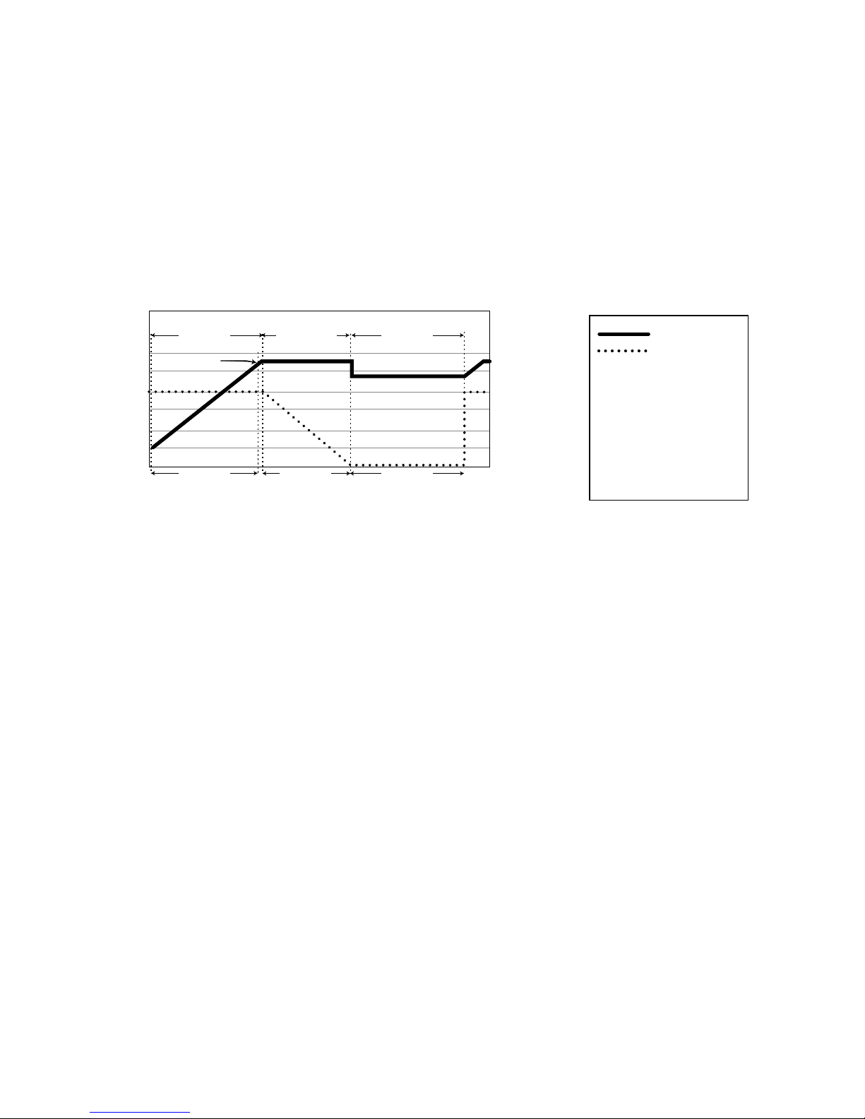
76 | SAMLEX AMERICA INC.
volt batteries (again, this voltage can vary based upon the desired values programmed through
the “Parameter Setting Menu” of the optional Remote Control Model EVO-RC (see Appendix
A). The Bulk Charge Stage restores about 75% of the battery’s charge. The Gassing Voltage
is the voltage at which the electrolyte in the battery begins to break down into Hydrogen and
Oxygen gases. Under normal circumstances, a battery should not be charged at a voltage above
its Gassing Voltage (except in the manually selected Equalization Stage) since this will cause the
battery to lose electrolyte and dry out over time.
This stage is displayed as "N-CC" in the Charging Mode screens in the Remote Control
EVO-RC (Please see Section 3.6.1 at Appendix A).
15
14
13
12
11
10
Charger Voltage, VDC
TIME
To T1 10 Days
CURRENT (%) of Set Bulk
Charge Current “Io”
100%
60%
0%
BULK
ABSORPTION
FL OAT
Voltage Curve
Current Curve
LEGEND
V
Absorp
- 0.3V
Note 1: The voltage curve
shows the voltage output of
charger. The intrinsic battery
voltage may be dierent and
will be proportional to the
state of charge.
Note 2: The graph is for 12V
version. For 24V version,
double the voltages.
Io
(Displayed as “N-CC”) (Displayed as “N-CV”) (Displayed as “Float”)
Fig 5.1 Charging Curve for Normal 3 Stage Charging
The value of the Bulk Charge Current “Io” depends upon the total Ampere Hour (Ah) capacity
of the battery or bank of batteries. A battery should never be charged at very high charging
current as very high rate of charging will not return the full 100 percent capacity as the Gassing
Voltage rises with higher charging current. As a general Rule of Thumb, the Bulk Charging
Current “Io” should be limited to 10% to 20% of the Ah capacity of the battery (20 Hr
Rate). Higher charging current may be used if permitted by the battery manufacturer.
Programmable range and Default values of Bulk Charge Current “Io” are shown in Table 6.2.
The units are shipped with the Bulk Charge Current set at the Default Value of 40A.
When the unit enters Charging Mode, it starts working as a battery charger and the charger
will run at full programmed Bulk Charge Current until the charger reaches the programmed
Absorption Voltage.
As part of the Adaptive Charging Algorithm, a software timer will measure the time taken from
the instant the unit enters the Bulk Charging Mode untill the instant the battery voltage reaches
0.3V below the programmed Absorption Voltage, then registers this time as Bulk Charge Time
To and computes the Absorption Time T1 as 10 times the Bulk Charge Time To in the internal
“T1 Timer” i.e. T1 = To x 10. The “T1 Timer” is used to determine the time the charging will
take place in the next Absorption Stage.
5.6.1.1 Automatic Adjustments of Internal AC Charger Current When External
Charger is Also Charging in Parallel
Please note that if an external charging source is also used to charge the batteries at the same
time in parallel with the internal AC charger of the unit, the charging current of the internal
AC charger will be controlled so that the total charging current of the external charger and the
internal charger is = the programmed Bulk Charging Current “Io”.
SECTION 5 | Battery Charging in Evolution Series
Page 77

For example, if the programmed charging current is say 40A and the charging current of the
external charger is 30A, the internal AC charger will output only 10A (Programmed setting of
40A – external charging current of 30A = 10A). Similarly, if the programmed setting is say 30A
and the external charger is 50A, the internal AC charger will not provide any charging.
5.6.2 Absorption Stage
During the Absorption Stage, the charging voltage is held constant near the Gassing Voltage
to ensure that the battery is further charged to the full capacity without overcharging. The
Absorption Stage restores the remaining 25% of the battery’s charge. The time the charger
remains in the Absorption Stage is proportional to the depth of discharge of the battery. When
the battery is more discharged, it will take longer time in the Bulk Charge Stage to reach the
Gassing Voltage. As a part of the Adaptive Charging Algorithm, the “T1 Timer” (explained
above) computes the time the charging takes place in this stage.
Absorption Time T1 = Bulk Charge Time To x 10 (To = Time from entering Bulk
Charge Stage till battery voltage rises to 0.3V below Absorption Voltage).
The “T1 Timer” has minimum time of 1 hour and a maximum time of 12 hours.
When the T1 Timer runs out, the charger will enter the next Float Stage.
Programmable range and Default values of Absorption Voltage are shown in Table 6.2.
This stage is displayed as "N-CV" in the Charging Mode screens in the Remote Control
EVO-RC (Please see Section 3.6.1 at Appendix A).
5.6.3 Float Stage
Float Stage is a maintenance stage in which the output voltage is reduced to a lower level, typically
about 13.5 volts, (27 volts for 24V models) to maintain the battery’s charge without losing electrolyte
through gassing and also prevent corrosion of Positive plate by maintaining proper Positive plate
Polarization Voltage. Programmable range value of Float Voltage are shown in Table 6.2.
This stage is displayed as "Float" in the Charging Mode screens in the Remote Control
EVO-RC (Please see Section 3.6.1 at Appendix A).
5.6.4 Automatic Resetting of Charging Cycle in 3 Stage Charging Prole
The charging cycle will be reset to the Bulk Stage as follows:
- If the AC input from the Grid/Generator is disconnected and is reconnected or the battery
voltage drops below 12 VDC / 24 VDC (Default). Programmable range for this voltage
is 10 to 13V for 12V battery and 20 to 26V for 24V battery (This parameter is called
"FLOATING EXIT". See Table 6.2 and Section 4.4 of Appendix A).
- If the charger remains in the Float Mode for 10 days.
5.7 4 STAGE CHARGING IN EQUALIZATION MODE
!
CAUTION!
Equalization Mode should be performed only on vented, ooded (non-sealed or
“wet”) batteries and not on the sealed AGM / Gel Cell batteries and only as often as
recommended by the battery manufacturer.
SECTION 5 | Battery Charging in Evolution Series
Page 78
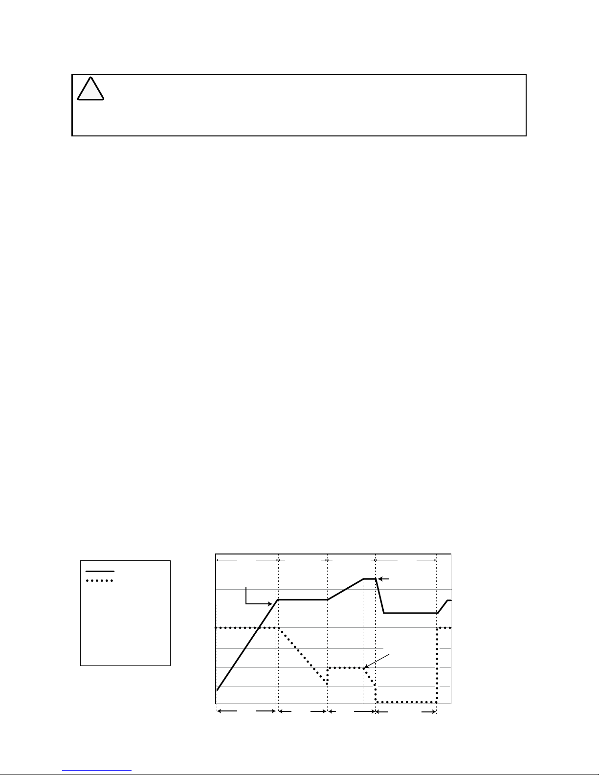
78 | SAMLEX AMERICA INC.
!
ATTENTION!
La mode d’égalisation devrait être faite sur des batteries ventillées, inondées (batteries non-scellées ou «mouillées»)
et pas sur des batteries scellées (AGM) ou cellulles gelées et, aussi souvent que les recommandations du fabricant.
4
Stage Battery Charging Cycle is used in the Equalization Mode. Equalization Mode is selected
using optional Remote Control EVO-RC (see Appendix A). Equalization of the batteries is carried
out periodically - normally once per month for battery under heavy duty service and every two
to four months for battery under light duty service. As equalization is a deliberate overcharge of
the battery for a specified time period, equalizing your flooded / wet cell batteries will reduce
sulfation, stir up the electrolyte to remove stratification, equalize voltages of individual cells and
thus, help reach and maintain the peak capacity of the battery.
The 4 stages of the cycle will be - Bulk, Absorption, Equalization, and Float. Equalization Mode is
desirable for the proper health of Wet Cell Batteries. Equalization voltage is programmable
through the optional Remote Control Model EVO-RC (see Appendix A). Programmable voltage
range and default values are shown in Table 6.2.
Equalization current and Equalization time are computed automatically. (See Section 5.8)
Fig 5.2 shows the voltage and current curves during the 4 stages of charging in this mode.
When Equalization is selected (requires optional Remote Control Model EVO-RC (see Appendix
A), the charger will first execute Bulk Stage followed by Absorption Stage. On completion of
Absorption Stage, the charger will execute Equalization Stage. After completion of Equalization
Stage, the charger will enter Float Stage. The stage transitions will thus be: Bulk Stage
(Constant Current) Absorption stage (Constant Voltage) Equalization Stage (Constant
Voltage) Float Stage (Constant Voltage).
As part of the Adaptive Charging Algorithm, the charging profile in the Equalization Stage is
based on the time To which is the time the charger remains in the initial Bulk Stage. The charger
will remain in the initial Bulk Stage for a longer duration when the battery is deeply discharged
and for a shorter duration if the battery has a shallow discharge.
Fig 5.2 Charging Curve for 4 Stage Charging in Equalization Mode
SECTION 5 | Battery Charging in Evolution Series
VDC
CURRENT (%) of Set
Bulk Charge Current Io
100
50
0
15
14
13
12
11
10
16
TIME
To T1’
T2
(Displayed as “Float”)
Io
I2 = 0.5 x lo
BULK ABSORPTION EQUALIZATION F LOAT
Set value of
Equalization
Voltage
V
Absorp
- 0.3V
10 Days
Voltage Curve
Current Curve
LEGEND
Note 1: The voltage curve
shows the voltage output of
charger. The intrinsic battery
voltage may be dierent and
will be proportional to the
state of charge.
Note 2: The graph is for 12V
version. For 24V version,
double the voltages.
(Displayed as “E-CC”) (Displayed
as “E-CVA”)
(Displayed
as “E-CVE”)
Page 79
!
CAUTION!
For effective equalization to take place, it is desirable that the batteries undergo a
longer Bulk Stage applicable to the deeply discharged condition of the battery.
Please ensure that before the batteries are equalized, they should be deeply
discharged to 20% of its capacity. The Standing Voltage (Terminal Voltage after
disconnecting charging source[s] and load[s] for at least 3 hours) at 20% capacity
will be:
o 12V Battery: Around 11.7V
o 24V Battery: Around 23.4V
Do not equalize partially or fully charged batteries
!
ATTENTION!
Pour une égalisation efcace, il faut que les batteries subissent à une étape majeure plus long en fonction de
la condition déchargée de la batterie.
Veuillez assurer que les batteries sont profondément déchargées (à 20% de sa capacité), avant de les
égaliser. La tension constante (la tension de la borne après avoir déconnecter toutes sources de charge
pour un minimum de 3 heures) quand elles sont déchargées à à 20% de sa capacité, serait:
o Une batterie de 12V: Environ 11,7V
o Une batterie de 24V: Environ 23,4V
N’égalisez pas des batteries qui sont partiellement ou complètement chargées
5.8 DETAILS OF EQUALIZTION MODE CHARGING CYCLE (Fig 5.2)
During the Bulk Stage, the charger will charge at the programmed Bulk Charge Current
“ Io “ (see programmable range at Table 6.2. Default value is 40A). Bulk Charge Current
“Io” is normally limited to 10%-20% of the Ah capacity of the battery (20Hr Rate). Higher
current may be used if permitted by the battery manufacturer in Equalization Mode. The
Bulk Stage is displayed as "E-CC" in the Charging Mode screens of the optional
Remote Control EVO-RC (Please refer to Section 3.6.1 at Appendix A).
A Software Timer is used to measure the time taken from the time the unit transfers to the
Utility / Generator Mode / enters Bulk Stage until the battery charger reaches 0.3V below
the Absorption Voltage, then registered this time as time To. The following times are computed based on the time To:
Absorption Time T1’ = To x 0.5
Equalization Time T2 is then computed based on the following logic:
T2 = T1’ + 1 hr = 0.5 To + 1 hr ; if T1’ < 2 hrs
T2 = T1’ + 2 hrs = 0.5 To + 2 hrs ; if 2 < T1’ < 4 hrs
T2 = T1’ + 4 hrs = 0.5 To + 4 hrs ; if T1’ > 4 hrs
When the battery reaches the programmed Absorption Voltage (see programmable range
and defaults at Table 6.2), it transitions to the Absorption Stage and remains in this stage
for the computed time T1’. This stage is displayed as "E-CVA" in the Charging Mode
screens in Remote Control EVO-RC (Please refer to Section 3.6.1 at Appendix A).
At the end of Absorption Stage, it transitions to the programmed Equalization Voltage (see
programmable range and defaults at Table 6.2). It remains in this stage for the computed
time T2. This stage is displayed as"E-CVE" in the Charging Mode screens in Remote
Control EVO-RC (Please refer to Section 3.6.1 at Appendix A).
SECTION 5 | Battery Charging in Evolution Series
Page 80

80 | SAMLEX AMERICA INC.
The equalization current “I
2
” is normally 5% to 10% of the Ah capacity of the battery.
This current is indirectly computed from the programmed Bulk Charge Current. As
recommended under the Setting Mode for the Bulk Charge Current, the Bulk
Charge Current “Io” is expected to be set at 10% to 20% of the Ah capacity of the
battery. Hence, the Equalization current “I
2
” will be automatically computed at 50% of
the set Bulk Charge Current “Io” which will effectively amount to 5% to 10% of the Ah
capacity of the battery. For example, the Equalization Current “I
2
” for a 200 Ah capacity
battery will be 10 A - 20A. The Bulk Charge current “Io” for a 200 Ah capacity at 10% 20% will be set at 20 A - 40A. The rmware will compute the Equalization Current “I
2
” at
50% of 20 A (i.e. 10A) or at 50% of 40A (i.e. 20A).
At the end of Equalization Stage, the charger transitions to the programmed Float Voltage
(see programmable range and defaults at Table 5.1). This stage is displayed as"Float"
in the Charging Mode screens in Remote Control EVO-RC (Please refer to Section
3.6.1 at Appendix A).
Automatic Resetting of Charging Cycle
The charging cycle will be reset to the Bulk Stage of 3 Stage Charging Prole as follows:
- If the AC is reconnected or the battery voltage drops below 12 VDC / 24 VDC (Default).
Programmable range for this voltage is 10 to 13V for 12V battery and 20 to 26V for 24V battery.
(This parameter is called "FLOATING EXIT". Please see Table 6.2 and Section 4.4 of Appendix A)
- If the charger remains in the Float Mode for 10 days.
5.9 SWITCHING ON AND SWITCHING OFF OF EQUALIZATION MODE
(4 STAGE CHARGING)
The unit comes preset for charging in Normal Charging Prole (3 Stage Charging Prole).
Equalization Prole (4 Stage Charging Prole) is required to be selected manually as follows:
Using ON/OFF Push Button on the Front Panel: When the unit is in Charging Mode (qualied
Grid / Generator Input is available), the Green LED “Status” will be ashing once per second.
Press the ON/OFF Button for 1 second. The ongoing Normal Charging Mode will be terminated
and Equalization Mode will be initiated. The Green “Status” LED will start ashing 2 times per sec
to show that Equalization Mode is active. The unit will complete Equalization Cycle and terminate
in Float Stage. At the same time, the Charge Mode Setting will again reset to Normal Mode
and the Green LED “Status” will return to 1 ash per second. To terminate Equalization Mode
prematurely before its completion, press the ON/OFF Push Button for 1 second.
If the unit was in Inverting Mode (Green LED “Status” steady) and the Mode is set to
Equalization as above by pressing the ON/OFF Push Button for 1 second, the unit will
undergo Equalization Mode whenever qualied AC input is available from Grid / Generator
and the unit enters Charging Mode. To terminate Equalization Mode prematurely before its
completion, press the ON/OFF Push Button for 1 second.
NOTE: Procedure described above is to be used when the optional Remote
Control EVO-RC has NOT been plugged into the RJ-45 Remote Control
Jack. Please note if the Remote Control has been plugged into the RJ45 Jack, the above procedure cannot be activated and the ON/OFF of
Equalization Mode will be controlled by the Remote Control EVO-RC.
Using Optional Remote Control EVO-RC: Please refer to the attached manual for
EVO-RC at Appendix A.
SECTION 5 | Battery Charging in Evolution Series
Page 81
BEFORE OPERATING THE UNIT, PLEASE ENSURE THAT THE UNIT HAS BEEN INSTALLED
PROPERLY AS PER INSTRUCTIONS AT SECTION 3 OF THIS MANUAL.
PLEASE ENSURE THAT ALL SAFETY INSTRUCTIONS AT SECTION 1 OF THIS MANUAL
ARE READ AND UNDERSTOOD BEFORE OPERATING THE UNIT.
INFO
a) Minimum battery voltage required for initiating manual switching ON of the unit
is as follows:
• 12V units ----- Higher than 9V
• 24V units ---- Higher than 18V
b) Please note that this unit is designed to POWER ON AUTOMATICALLY if (i) minimum
battery voltage of 12V/24V as at (a) above is available at the DC input terminals and
(ii) AC voltage > 60VAC is available at the Grid / Generator Input Terminals. If the AC
input voltage and frequency are within the programmed limits, the unit will automatically operate in “Charging Mode”. If the AC input voltage and frequency are not within
the programmed limits, the unit will operate in “Discharging / Inverter Mode”. Further,
as long as AC input voltage > 60VAC is present, the unit CANNOT BE POWERED OFF
using the ON / OFF Button on the front panel of the unit or on the optional Remote
Control EVO-RC (see Appendix A). Switch OFF the AC input rst if the unit is required
to be powered off. However, if the unit is in “Fault Mode”, it will be possible to power
OFF the unit with the help of the ON/OFF Push Button
c) Before proceeding, conrm that the unit is NOT in Standby Mode by pressing ON/
OFF Button briey. (Standby Mode is used for Firmware upload through the optional
Remote Control EVO-RC (see Appendix A))
o If LED marked “ON” (12, Fig 2.1) stays OFF, then unit is OFF.
o If this LED is ON or is ashing, the unit was in Standby Mode and is now ON
6.1 POWERING ON USING ON/OFF BUTTON ON THE FRONT PANEL
(11, Fig 2.1)
6.1.1 Powering ON
To power ON the unit, press and hold the ON/OFF Button (11, Fig 2.1) for 2 seconds.
Green LED marked “ON” (12, Fig 2.1) will ash 3 times, will go off momentarily and will
then be steady Green. Now, release the ON/OFF Button. Subsequently, the lighting pattern of this LED will be controlled by various operating conditions given in Table 6.1
6.1.2 Powering OFF
To power OFF the unit, press and hold the ON/OFF Button (11, Fig 2.1) for 5 seconds.
Wait for the Green LED marked “ON” (12, Fig 2.1) and Red LED marked
“FAULT” (13, Fig 2.1) to light steady and then release the ON/OFF Button. The
unit will power OFF after the ON/OFF Button is released. (NOTE: Power OFF will
not take place unless the Power ON/OFF Button is released)
NOTE: As explained under paragraph (a) of “Info” above, as long as
AC input voltage > 60VAC is present, the unit CANNOT BE POWERED
OFF using the ON/OFF Button on the front panel of the unit or on the
optional Remote Control EVO-RC (see Appendix A). In order to power off
using the Power ON/Off Button, switch OFF the AC input rst. Further, if
the unit is in “Fault Mode”, it will be possible to power OFF the unit with
the ON/OFF Push Button.
SECTION 6 | Operation, Protections and Troubleshooting
Page 82

82 | SAMLEX AMERICA INC.
6.2 POWERING ON / OFF BY FEEDING EXTERNAL +12V CONTROL
SIGNAL TO TERMINALS MARKED “REMOTE ON/OFF” ON THE
FRONT PANEL (15, FIG 2.1)
Programming option is available through the Parameter Setting Menu (Parameter is called
"REMOTE SWITCH") of the optional Remote Control Model No. EVO-RC (Please see Section
4.8 of Appendix A) for 2 types of external +12V control signal fed through Remote ON/OFF
Terminal (15, Fig 2.1). Details of these options are given below:
6.2.1 Button Type (Default)
This type of logic is applicable when the +12V Control Signal is fed through a series
connected Push Button contact. Control logic used is as follows:
• When the unit is in OFF condition, a momentary contact of the Push Button > 2
seconds will turn the unit ON.
• When the unit is in ON condition, pressing of the Push Button < 5 seconds will have no
effect and the unit will continue to remain in ON condition.
• When the unit is in ON condition, pressing the Push Button > 5 seconds will turn the
unit OFF.
6.2.2 Switch Type
This type of logic is applicable when the +12V Control Signal is fed through a series
connected external manual Switch or through an external relay contact. Logic used is as
follows:
• When the unit is in OFF condition, toggling the external manual switch to ON position or
closing the external relay contact will immediately turn the unit ON.
• When the unit is in ON condition, toggling the external manual switch to OFF position
for 2 seconds or opening the relay contact for 2 sec will turn the unit OFF.
CAUTION: When “Switch Type” of ON/OFF control described above is selected, the
ON/OFF Button on the front panel of the unit (12, Fig 2.1) should NOT be used to
turn ON or turn OFF the unit. The front panel ON/OFF Push Button will now follow
the above “Switch Type” control logic wherein the unit will remain ON only as long
as the Button is kept pressed and will turn OFF in 2 seconds after it is released.
6.3 OPERATIONAL INFORMATION THROUGH LEDS AND BUZZER
Table 6.1 shows the operational states of the unit indicated by the following LEDs on the
front panel of the unit and Buzzer:
o Green LED marked “ON” (12, Fig 2.1)
o Red LED marked “Fault” (13, Fig 2.1)
Optional Remote Control Model EVO-RC (see Appendix A) will be required for more detailed
messaging that is available through its LCD display and LEDs. This remote will also be required
for programming of various parameters to suit specic requirements.
SECTION 6 | Operation, Protections and Troubleshooting
Page 83

TABLE 6.1 LED AND BUZZER INDICATIONS
Status
Green LED
marked “ON”
(12, Fig 2.1)
Red LED
marked
“Fault” (13, Fig
2.1)
Buzzer
Seen during Power-On
Sequence
Indicates completion of
Power-On Sequence after
Power ON/OFF Button is
pressed for 2 sec
Flash 3 times Off Off
Seen during Power-Off
Sequence
Indicates completion of
Power-Off Sequence after
Power ON/OFF Button is
pressed for 5 sec
On On Off
Normal charging Flash 1 time per sec Off Off
Equalization charging Flash 2 times per
sec
Off Off
Inverting (Discharging) On Off Beep per 3 second
(Default Off)
Low battery alarm On Flash 1 per sec Beep per 1 second
Power saving Flash 1 time per
3 sec
Off Off
Standby Off Off Off
Fault Off On On
6.4 OPTIONAL REMOTE CONTROL EVO-RC (see Appendix A) FOR
PROGRAMMING OF MODES OF OPERATION AND PARAMETERS
Optional Remote Control Model EVO-RC (Fig 2.4) will be required for more advanced control
and monitoring. Please see separate Owner’s Manual for EVO-RC at Appendix A. The Remote
Control comes with 10M / 33 ft., RJ-45 Data Cable. The Remote plugs into RJ-45 Jack on
the front panel of the unit (7, Fig 2.1). It has provision for Data Logging using SD Card of up
to 16 GB (FAT16 / FAT32). It also has its own Real Time Clock and Super Capacitor Type of
Battery.
Detailed messaging is available through its LCD display and LEDs. This remote will also
be required for programming of various parameters to suit specic requirements. Each
programmable parameter has a Default Value. This unit has been shipped with the various
parameters set at the Default Values. Programmable and Default values are shown in Tables
6.2 to 6.6:
SECTION 6 | Operation, Protections and Troubleshooting
Page 84
84 | SAMLEX AMERICA INC.
TABLE 6.2 PROGRAMMABLE AND DEFAULT PARAMETERS: GROUP CHARGING CURVE
Parameter
Programming Range
(Programming requires optional Re-
mote Control Model EVO-RC)
Default
EVO2212
EVO-
3012
EVO-
2224
EVO4024
EVO-
2212
EVO3012
EVO2224
EVO-
4024
“BULK CURRENT”
(Bulk Charge Current “Io”)
0-100A 0-130A 0-70A 0-110A 40A
“ABSORP VOLTAGE”
(Absorption Voltage)
13.5V - 16.0V 27.0V - 32.0V 14.4V 28.8V
“EQUALIZE VOLTAGE”
(Equalization Voltage)
14.0V - 16.0V 28.0V - 32.0V 14.4V 28.8V
“FLOATING VOLTAGE"
(Float Voltage)
13.0V - 15.0V 26.0V - 30.0V 13.5V 27.0V
“COMPENSATE”
(Temperature Compensation)
-3mV to -5mV /°C/Cell -4mV /°C/Cell
“LOW VOLT ALARM”
(Battery Low Voltage Alarm)
9.5V - 12.5V 19.0V - 25.0V 11.0V 22.0V
“BATT LOW VOLTAGE”
(Battery Low Voltage Shut
Down)
9.1V - 12.0V 18.1V - 24.0V 10.5V 21.0V
“LV DETECT TIME”
(Low Voltage Detect Time)
0-600 sec 10 sec
“LV CUT OFF TIME”
(Low Voltage Cut Off Time)
0-7200 sec 1200 sec
“RESET VOLTAGE”
(Battery Low Voltage Reset)
12.0V - 17.0V 24.0V - 35.0V 14.0V 28.0V
“BATT OVER VOLT”
(Battery Over Voltage Shut
Down)
14.0V - 17.0V 28.0V - 35.0V 16.0V 32.0V
“CHARGE MODE”
( 3 or 4 Stage Charging)
Normal (3-Stage) / Equalization (4-Stage) Normal (3-Stage)
"ONLINE MODE" or
"OFFLINE MODE"
0 = Off 1 = On 0 = Off
"ONLINE OPTIONS"
(For On-Line and Off Line
Modes)
0 = Option 1
1 = Option 2
0 = Option 1
"FLOATING EXIT" 10.00V to 13.00V 20.00V to 26.00V 12.00V 24.00V
"GS DETECT TIME" 0 - 600 sec 10 sec
"GEN ON TIME" 0 - 240 min 60 min
"GEN OFF TIME" 0 - 240 min 60 min
SECTION 6 | Operation, Protections and Troubleshooting
Page 85
TABLE 6.3 PROGRAMMABLE AND DEFAULT PARAMETERS - GROUP "INPUT SETTING"
Group
Parameter
name
Programming Range Default value
EVO2212
EVO3012
EVO2224
EVO-
4024
EVO-
2212
EVO-
3012
EVO-
2224
EVO4024
INPUT
SETTING
DEFAULT FREQ
0 = 60Hz
1 = 50Hz
0 = 60Hz
GRID MAX
CURRENT
5 – 40A 5 – 70A 5 – 40A 5 – 70A 30A
GEN MAX
CURRENT
5 – 40A 5 – 70A 5 – 40A 5 – 70A 30A
HIGH CUT OFF 50 – 70Hz 65Hz
HIGH RESET 50 – 70Hz 64Hz
LOW CUT OFF 40 – 60Hz 55Hz
LOW RESET 40 – 60Hz 56Hz
TABLE 6.4 PROGRAMMABLE AND DEFAULT PARAMETERS - GROUP "INPUT LOW LIMIT"
Group Parameter name
Setting range Default value
EVO2212
EVO3012
EVO2224
EVO4024
EVO2212
EVO3012
EVO2224
EVO4024
INPUT -
LOW LIMIT
RESET VOLTAGE 60.0 – 100.0V 95.0V
CUT OFF POINT 1 60.0 – 100.0V 90.0V
DETECT TIME 1 0 – 2000 cycle 300 cycle
CUT OFF POINT 2 60.0 – 100.0V 85.0V
DETECT TIME 2 0 – 2000 cycle 60 cycle
CUT OFF POINT 3 60.0 – 100.0V 80.0V
DETECT TIME 3 0 – 2000 cycle 1 cycle
TABLE 6.5 PROGRAMMABLE AND DEFAULT PARAMETERS - GROUP "INPUT HIGH LIMIT"
Group Parameter name
Setting range Default value
EVO2212
EVO3012
EVO-
2224
EVO4024
EVO2212
EVO3012
EVO-
2224
EVO-
4024
INPUT -
HIGH LIMIT
RESET VOLTAGE 100.0 – 150.0V 135.0V
CUT OFF POINT 1 100.0 – 150.0V 140.0V
DETECT TIME 1 0 – 2000 cycle 300 cycle
CUT OFF POINT 2 100.0 – 150.0V 145.0V
DETECT TIME 2 0 – 2000 cycle 60 cycle
CUT OFF POINT 3 100.0 – 150.0V 150.0V
DETECT TIME 3 0 – 2000 cycle 1 cycle
SECTION 6 | Operation, Protections and Troubleshooting
Page 86
86 | SAMLEX AMERICA INC.
TABLE 6.6 PROGRAMMABLE AND DEFAULT PARAMETERS - GROUP "OTHER FUNCTIONS"
Parameter name
Setting range Default Value
EVO-
2212
EVO3012
EVO2224
EVO4024
EVO2212
EVO3012
EVO2224
EVO4024
“POWER SAVING” 1 = Enable 0 = Disable Enable
“ENTER POINT” 4 – 50W 6W 8W 6W 8W
“WAKE UP POINT” 5 – 50W 7W 10W 7W 10W
“REMOTE SWITCH”
For ON /OFF control
through external 12V
signal fed to Remote
ON / OFF terminals on
the Front Panel (15,
Fig 2.1)
0 = Button Type: 12V signal is fed
through Push Button Type of Switch
Pressing of Push Button > 2 sec
will switch the unit ON
When ON, pressing Push Button
> 5 sec will turn the unit OFF
1 = Switch Type: 12V signal is fed
through contacts of Toggle Type of
Switch or relay contact
ON condition (contacts closed)
will turn the unit ON
OFF condition (contacts open)
for 2 sec will switch the unit OFF
0 = Button Type
CAUTION! ON/OFF Logic also controls the
operation of the ON/OFF Button on the
front panel (11, Fig 2.1). The Default setting
is "Button Type".
If the ON/OFF Control is changed to external
"Remote Switch", it will not be possible to
switch ON/OFF the EVO Inverter/Charger
from the front panel ON/OFF Push Button
because it will work with Switch Type
Logic. It will be ON only as long as the Push
Buttom is kept pressed and will switch OFF
when released.
“RELAY FUNCTION”
(for Status Relay)
0 = Charge / Other
OFF in "Charging" Mode
ON in other Modes i.e. "Inverting",
"Power Saving" or "Standby"
1 = Normal / Fault
OFF in normal operating conditions
ON in Fault Modes
2 = Generator 0
ON when batteries drop to "LOW
VOLT ALARM" or lower for period
= "GS DETECT TIME" - Initiates
Generator start
OFF after batteries are completely
charged till Float Stage - initiates
Generator stop
3 = Generator 1
ON when batteries drop to "LOW
VOLT ALARM" or lower for period
= "GS DETECT TIME" - initiates
Generator start
OFF when batteries are charged
to "RESET VOLTAGE" for period =
"GEN OFF TIME" - initiates Generator stop
4 = Generator 2
ON when batteries drop to "LOW
VOLT ALARM" or lower for period
= "GS DETECT TIME" - initiates
Generator start
OFF after period = "GEN ON TIME"
from the time relay switched ON initiates Generator stop
2 = Generator 0
Table continues on next page }
SECTION 6 | Operation, Protections and Troubleshooting
Page 87
TABLE 6.6 PROGRAMMABLE AND DEFAULT PARAMETERS - GROUP "OTHER FUNCTIONS" (Continued)
Parameter name
Setting range Default Value
EVO2212
EVO3012
EVO2224
EVO-
4024
EVO-
2212
EVO-
3012
EVO-
2224
EVO-
4024
“COMM ID”
(Communication ID for
optional Remote Control
EVO-RC)
1 - 255 1
“BUZZER” 0 = OFF ; 1 = ON 1 = On
“DISCHARGE BEEP”
(Beeping in “Discharging / Inverter Mode”)
0 = OFF ; 1 = ON 0 = Off
“DEFAULT RESET” 0 = No ; 1 = YES 0 = No
DATA LOG TIME
(For Optional Remote
Control EVO-RC)
0 = Disable 3 = 30 sec 6 = 10 min
1 = 1 sec 4 = 60 sec 1
2 = 10 sec 5 = 5 min 1
1 = 1 sec
PARAMETER SAVE
(For Optional Remote
Control EVO-RC)
0 = No
1 = Yes
0 = No
6.5 PROTECTIONS, FAULT MESSAGES AND TROUBLESHOOTING GUIDE
The front panel of the unit has a Red LED marked “FAULT” (13, Fig 2.1). This LED will light
up (steady) when the unit registers any of the FAULT MODE situations shown in Table 7.1 of
EVO-RC Manual at Appendix A.
Table 7.1 of EVO-RC Manual at Appendix A shows details of protections and associated Fault/
Error Messages that will be displayed on the LCD screen of the optional Remote Control EVO-RC.
NOTE: If the optional Remote Control EVO-RC (see Appendix A) is not used, it may be
difcult to narrow down the probable cause of the fault.
6.6 POWERING OFF THE UNIT IN FAULT MODE
If the unit is in “Fault Mode”, it will be possible to power OFF the unit with the ON/OFF Push
Button.
(As explained under paragraph 6.1.2, as long as AC input voltage > 60VAC is present, the
unit CANNOT BE POWERED OFF using the ON / OFF Button on the front panel of the unit or
on the optional Remote Control EVO-RC (see Appendix A). In order to power off using the
Power ON/Off Button, switch OFF the AC input rst).
SECTION 6 | Operation, Protections and Troubleshooting
Page 88

88 | SAMLEX AMERICA INC.
6.7 12V, 100mA CAPACITY DC SOURCE FOR SIGNALING
A 12V, 100mA capacity DC source has been provided (16, Fig 2.1). This voltage may be
routed through the contacts of the Status Relay (14, Fig 2.1) to feed 12V ON / OFF control
signal to drive circuits of remote monitoring control of the programmable conditions of
operation of the unit (Refer to Table 6.6 under Relay Function).
6.8 STANDBY MODE
This Mode is required to be switched ON manually during rmware uploading procedure
for EVO Inverter Charger. Firmware upload is carried out through the SD Card slot provided
on the optional Remote Control Model EVO-RC [9, Fig 2.4(a)]. When rmware uploading
procedure is initiated, the user will be prompted to switch ON Standby Mode – message on
the LCD screen on the EVO-RC will show “Press power key to stop inverter”. Once rmware
upload is completed, the EVO exits the Standby Mode automatically. Please refer to Section
3.4 of the EVO-RC Remote Control Owner’s Manual at Appendix A.
NOTE: Standby Mode may also be used to temporary halt normal operation of the Inverter
Charger without switching OFF the unit completely.
For the Standby Mode to be switched ON, the EVO should be in ON condition and should be
operating in one of the 3 Operating Modes – “Inverting” or “Charging” or “Power Saving”
(See Fig 3.1 of the EVO-RC Owner’s Manual at Appendix A). When Standby Mode is switched
ON, the EVO will exit its Operating Mode.
Standby Mode is toggled between ON and OFF conditions as follows:
By momentary pressing (0.1 sec) of ON/OFF Push Button on the front panel of the unit
(11, Fig 2.1)
By momentary pressing (0.1 sec) of ON/OFF Push Key on the optional Remote Control
EVO-RC [2, Fig 2.4(a)]
When the EVO is in “Standby Mode”, operational status will be displayed as follows:
On the front panel of EVO:
- No LED display. Green LED marked “ON” (12, Fig 2.1) and Red LED marked “FAULT”
(13, Fig 2.1) will both be OFF.
- No buzzer
On the Remote Control EVO-RC:
- No LED display. Green LED marked “Status” (3, Fig 2.4a) and Red LED marked
“FAULT” (4, Fig 2.4a) will both be off
- The LCD will display
STANDBY
BATTERY XX.XXV
(Fig 3.1 in the EVO-RC Owner’s Manual at
Appendix A)
- No buzzer
SECTION 6 | Operation, Protections and Troubleshooting
Page 89
!
CAUTION!
When EVO is operating normally, the front panel Green LED marked “ON” (12, Fig 2.1)
will be ON or ashing based on the operational status of EVO (TABLE 6.1). If the ON / OFF
Push Button (11, Fig 2.1) gets accidentally pressed momentarily, the EVO will switch over to
Standby Mode and normal operation will be interrupted. There will be no LED display on the
front panel of the EVO: Green LED marked “ON” (12, Fig 2.1) and Red LED marked “FAULT”
(13, Fig 2.1) will both be OFF. The buzzer will also be OFF. If Remote Control EVO-RC was not
being used for monitoring, the user may think that the unit has quit working / become defective. Hence, if at any time during the operation of EVO, no LED activity is seen on the front
panel of the unit, it is likely that the unit may have been switched over to “Standby Mode”
accidentally. To exit from “Standby Mode” and revert to the normal operating mode , press
the ON/OFF Push Button on the front panel of the unit (11, Fig 2.1) momentarily (0.1 sec). If
the EVO does not switch over to normal operating mode, carry out further troubleshooting.
!
ATTENTION!
Lorsque l’EVO fonctionne normalement, le panneau d’avant LED verte marquée «ON» (12, gure 2,1) sera ON ou
clignotera en fonction de l'état opérationnel de l’EVO (tableau 6,1). Si le bouton ON/OFF (11, gure 2,1) est accidentellement poussé momentanément, l'EVO déclenchera en mode veille et le fonctionnement normal sera interrompu. Il
n'y aura pas d'afchage LED sur la face avant de l'EVO: LED verte marquée «ON» (12, gure 2,1) et LED rouge marqué
"FAUTE" (13, gure 2,1) seront tous les deux OFF. La sonnerie sera également OFF. Si le RC-EVO n'a pas été utilisé pour
la surveillance, l'utilisateur peut penser que l'appareil a cessé de travailler / devenu défectueux. Ainsi, si à tout moment
pendant le fonctionnement de l’EVO, aucune activité de LED est visible sur la face avant de l'appareil, il est probable que
l'unité peut avoir été mise en "mode veille" accidentellement. Pour sortir du "mode veille" et revenir au mode de fonctionnement normal, appuyez sur le bouton ON/ OFF sur le panneau avant de l'appareil (11, gure 2,1) momentanément
(0,1 sec). Si l'EVO ne se met pas en mode de fonctionnement normal, effectuer un dépannage plus approfondi.
SECTION 6 | Operation, Protections and Troubleshooting
Page 90
90 | SAMLEX AMERICA INC.
Models EVO-2212 EVO-3012 EVO-2224 EVO-4024
INVERTER SECTION
Output Waveform Pure Sine Wave
Input Battery Voltage Range 9.1 - 17 VDC 18.1 - 34 VDC
Nominal AC Output Voltage 120 VAC ± 5%
Output Frequency 60 Hz ± 0.1 Hz
Total Harmonic Distortion of Pure
Sine Wave Form (THD)
< 5%
Continuous Output Power 2200 VA 3000 VA 2200 VA 4000 VA
Continuous AC Output Current 18A 25A 18A 33A
Surge Power for 1 msec
300%
(6600 VA, 54A)
300%
(9000VA, 75A)
300%
(6600VA, 54A)
300%
(12,000 VA, 99A)
Surge Power for 100 msec
200%
(4400VA, 36A)
200%
(6000VA, 50A)
200%
(4400VA, 36A)
200%
(8000VA, 66A)
Power Boost for 5 sec
150%
(3300W)
150%
(4500W)
150%
(3300W)
150%
(6000W)
Power Boost for 30 sec
140%
(3080W)
140%
(4200W)
140%
(3080W)
140%
(5600W)
Power Boost for 5 min
120%
(2640W)
120%
(3600W)
120%
(2640W)
120%
(4800W)
Power Boost for 30 min
110%
(2420W)
110%
(3300W)
110%
(2420W)
110%
(4400W)
Maximum Continuous DC Input
Current
266 A 373 A 133 A 266 A
Inverter Efciency (Peak)
90% 90% 93% 94%
No Load Power Consumption in
Power Saving Mode
< 8 W
No Load Power Consumption in
Normal Mode
(120 VAC Output, Typical)
30 watts 25 watts
AC INPUT FROM GRID / GENERATOR
AC Input Voltage 120VAC (60-140VAC +/- 5%)
AC Input Frequency 60Hz / 50Hz
Maximum Programmable (Default)
AC Input Current
5-40A
(Default 30A)
5-70A
(Default 30A)
5-40A
(Default 30A)
5-70A
(Default 30A)
TRANSFER CHARACTERISTICS
Transfer Relay Type and Capacity SPDT, 40A
DPDT, 70A
(2X35A contacts
in parallel)
SPDT, 40A
DPDT, 70A
(2X35A contacts
in parallel)
Transfer Time – Inverter to Grid /
Generator
< 1 ms (Synchronized Transfer at Zero Crossing)
Transfer Time – Grid / Generator
to Inverter
Up to 16ms (Synchronized Transfer)
SECTION 7 | Specications
Page 91
Models EVO-2212 EVO-3012 EVO-2224 EVO-4024
OPERATING MODES
OFF-LINE Mode
Grid/Generator Priority (Default)
• Grid/Generator supplies AC loads and charges batteries
• Inverter is standby
ON-LINE Mode
Battery / Inverter Priority (Programmable)
• Inverter supplies AC loads even if Grid/Generator is available
• Grid/Generator takes over when batteries are discharged to "Battery
Low Alarm" to charge batteries and to power AC loads. AC loads are
transferred back to Inverter under various programmed conditions
INTERNAL BATTERY CHARGER SECTION
AC Input Voltage Range
120 VAC (60 to 140 VAC +/-5% )
Max Continuous AC Input Current 15A, AC 20A, AC 19A, AC 30A, AC
AC Input Power Factor
> 0.95
Programmable DC Output Charging Current
0-100A, DC 0 - 130A, DC 0 - 70A, DC 0 - 110A, DC
Charger Efciency 75% 86% 85%
Charging Stages
Normal Mode: 3 Stages – Bulk, Absorption and Float
Equalization Mode: 4 Stages – Bulk, Absorption, Equalization and Float
Adaptive Charging Control
Battery Temperature Compensation
Battery Temperature Sensor included
Compensation Range from -20° C to 60° C
EXTERNAL BATTERY CHARGER SECTION (Solar Charge Controller)
Charging Voltage Range 13-15VDC 13-15VDC 26-30VDC 26-30VDC
Maximum Charging Current 50A
COOLING, PROTECTIONS AND ALARMS
Cooling
2 Fans – Temperature Controlled, Variable Speed
Protections and Alarms
Battery Low Voltage Alarm and Low / Over Voltage Shut Down
Shut Down under Input Over Current, Output Over Current, Output Over-
load and Output Short
Transformer and Heat Sink Overheat Shut Down
Immunity Against Conducted Electrical Transients in Vehicles
OPTIONAL REMOTE CONTROL
Model No.
EVO-RC (see Appendix A)
Specications
Advanced Features for programming various parameters and modes of
operation
2 Rows of 16 Character Alpha Numeric LCD Display for messaging
Up to 16 GB SD Card Slot for Data Logging
Comes with 10M / 33ft RJ-45 Data Cable
SECTION 7 | Specications
Page 92
92 | SAMLEX AMERICA INC.
SAFETY AND COMPLIANCE
Safety Compliance
Intertek-ETL listed: Conforms to ANSI / UL STD. 1741
Intertek-ETL listed: Certied to CAN / CSA STD. C22.2 No. 107.1-01
Intertek-ETL listed: Conforms to ANSI / UL STD. 458 with Marine
Supplement*
EMI / EMC Compliance
Certied to FCC Part 15(B), Class B
ENVIRONMENTAL SPECIFICATIONS
Operating Temperature
-20° C to +60° C (-4° F to 140° F)
Storage Temperature
-40° C to +70° C (-40° F to 158° F)
Operating Humidity
0 to 95% RH non condensing
WEIGHTS AND DIMENSIONS
Dimensions: W x D x H 325 x 426 x 207 mm; 12.79 x 16.77 x 8.15 in
Weights: 27 Kg / 59 lb. 29 kg / 64 lb. 26 Kg / 57 lb. 29 Kg / 64 LB
NOTES:
(1) All AC power ratings in the Inverter Section are specied at Power Factor = 0.95
(2) All specications given above are at ambient temperature of 25°C / 77°F unless specied
otherwise
(3) Specications are subject to change without notice
(4) * Marine Supplement is valid when installed using Drip Shield. Please see Figs 3.1(a),
3.2(b), 3.3(b) and 3.4(b).
SECTION 7 | Specications
Page 93

Remote Control
for Evolution
Series Inverter/
Charger
Model: EVO-RC
Please read this
manual bEfORE
operating.
firmware:
Rev 018
Owner's
Manual
APPENDIX A
NOTE: REMOTE CONTROL MODEL NO. EVO-RC IS OPTIONAL AND IS REQUIRED TO BE ORDERED SEPARATELY.
Page 94

APPENDIX A
EVO-RC OWNER'S MANUAL | Index
SECTION 1
Safety Instructions, Introduction and Layout ......................... 3
SECTION 2
Installation ........................................................................... 4
SECTION 3
Operation .......................................................................... 6
SECTION 4
Parameter Setup ................................................................ 11
SECTION 5
SD Card ......................................................................... 38
SECTION 6
Monitoring of Operation Using LED and Buzzer ................ 43
SECTION 7
Fault Messages and Troubleshooting Guide ....................... 44
SECTION 8
Specications ..................................................................... 47
SECTION 9
Warranty ......................................................................... 48
Page 95
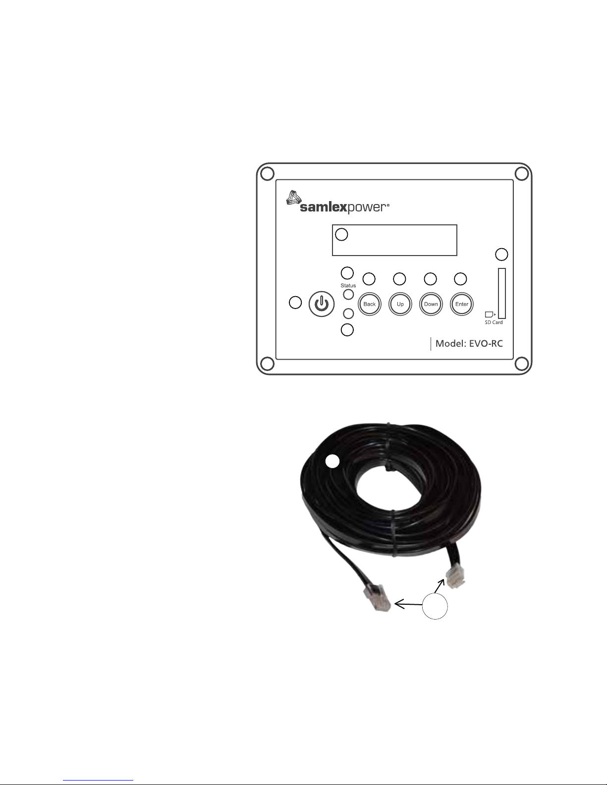
SAMLEX AMERICA INC. | 3
APPENDIX A
SECTION 1 | Safety Instructions,
Introduction and Layout
1.0 INTRODUCTION AND LAYOUT
The EVO-RC Remote Control allows you to monitor and customize the operating parameters
of Samlex EVO Inverter Charger Models EVO-2212, 2224, 3012 and 4024. Layout is shown in
Fig. 1.1(a) and (b) below.
RJ-45
Plug
11
Fig. 1.1(b) Cable For Remote Control EVO-RC
1. LCD Screen – 2 rows of
16 characters each
2. ON/OFF Key
3. Green LED "Status"
4. Red LED "Fault"
5. Navigation Key "Back"
6. Navigation Key "Up"
7. Navigation Key "Down"
8. Navigation Key "Enter"
9. SD Card Slot – FAT16/32 format; Up to 16 GB
10. RJ-45 Jack (At the back-not
shown)
11. RJ-45 Data Cable (Straight
Wired), 10 meter/33 feet length
{Fig1.1(b)}
Fig. 1.1(a) Optional Remote Control EVO-RC – Layout
Fault
2
5
3
4
6
7
8
9
1
Page 96
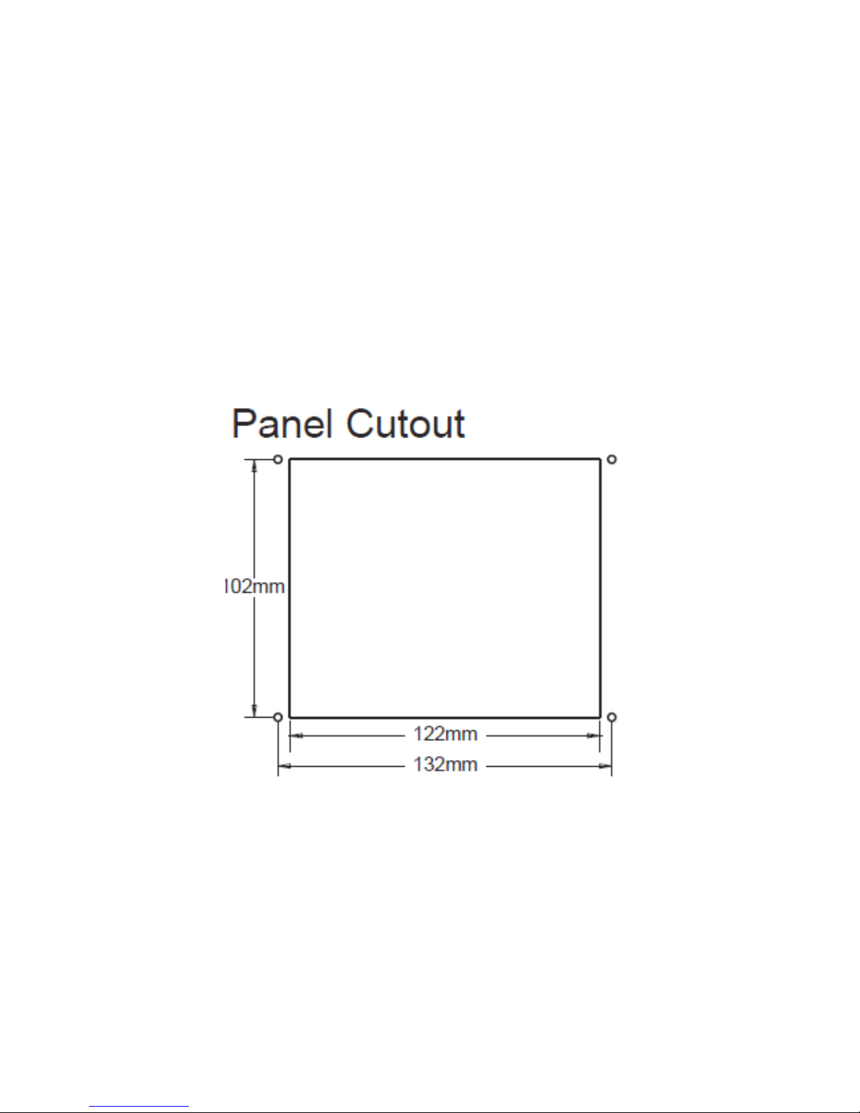
4 | SAMLEX AMERICA INC.
APPENDIX A
SECTION 2 | Installation
2.1 INSTALLATION GUIDELINES
The remote control is provided with 10M/33ft, RJ-45 Data Cable (Straight Wired). Check the
proposed routing distance of the wire and use longer wire, if necessary.
• Flush mounting of the Remote requires appropriate cut-out in the wall/panel. Take
necessary precautions to ensure any wiring/plumbing running behind the wall/panel is
not damaged.
• Route the wire to ensure there are no kinks.
• Use appropriate grommets when the wire is passed through holes in studs/partitions to
prevent damage to insulation.
2.1.2 Tools Required
Following tools are recommended:
• PhillipsHeadScrewdriver • Level • HandDrill
• Knife/Saw • Pencil • DrillBit(2.5mm/#39)
Fig 2.1 EVO-RC Remote Cutout Dimensions
2.2 FLUSH MOUNT INSTALLATION
To ush mount, the wall opening must have at least a 2” (5 cm) depth to make room for the
remote and cable. Also, the thickness of wall/panel board at the place of mounting should not
be more than 13 mm to ensure that the RJ-45 jack opening is not obstructed (see Fig. 2.3).
1. Cut an opening in the wall using the supplied paper template (based on Fig 2.1).
2. Drillfourpilotholes(use2.5mmdiameter/#39drillbit)forthe4screws(3mmdiameter,
16mm long) that will attach the remote to wall (refer to Figure 2.1 for hole locations and
dimensions).
3. Route one end of the cable through wall opening to the EVO Inverter Charger, and then
plug it into the RJ45 Remote Control Jack port on the EVO Inverter Charger.
Page 97
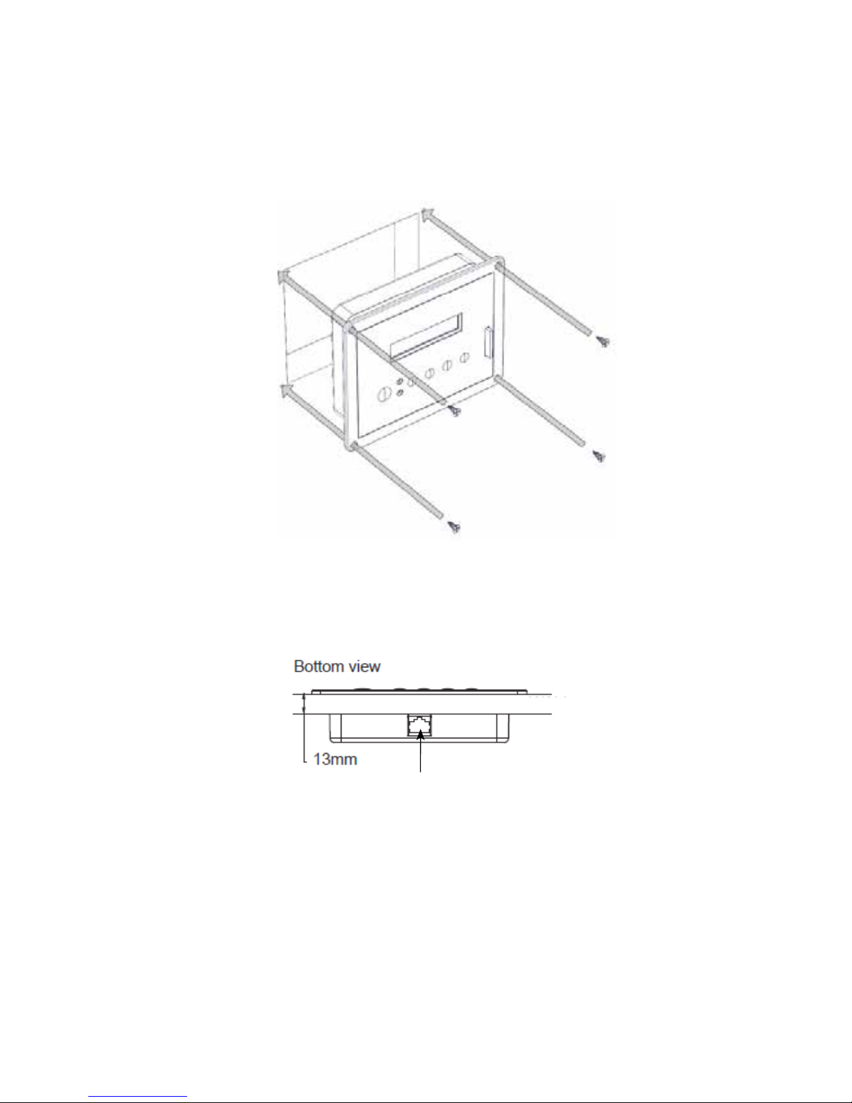
APPENDIX A
SECTION 2 | Installation
4. Take the other end of remote cable and plug it into the RJ-45 Jack at the back of
the EVO-RC (Fig. 2.3).
5. Check the remote display to ensure the Power-up self test initiates.
6. If the self test is successful, secure the EVO-RC to the wall using the four screws. (Fig 2.2)
The thickness of the wall/panel board at the place of mounting should
not be more than 13mm to ensure that the RJ-45 jack opening is not
obstructed.
Fig 2.3 Wall/Panel Thickness
RJ-45 Jack
WALL / PANEL BOARD
Flush mounting the EVO-RC on the wall with 4pcs, Φ3mm self-tapping
screws (at head).
Fig 2.2 EVO-RC Flush Mounting
Page 98

6 | SAMLEX AMERICA INC.
APPENDIX A
SECTION 3 | Operation
3.0 GENERAL INFORMATION
EVO-RC Remote Control provides the user with the ability to modify EVO Inverter Charger’s
operating parameters. The default settings in EVO Inverter Charger are adequate for some
installations but may have to be modied for others. This Section provides details on the remote
functions, status and menu maps and displays, fault messages and parameter settings.
3.1 NAVIGATING THE REMOTE
The EVO-RC provides menu items and adjustable settings to congure your EVO Inverter
Charger to your specic parameters. Please refer to the layout at Fig 1.1(a).
• LCD Display (1) – The 2-line (16 characters each) LCD display shows status and
information for the EVO Inverter Charger. All Setup Menus and faults also appear on the
LCD display.
• ON/OFF Key (2) – The ON/OFF Key is used for switching ON/switching OFF the EVO
Inverter Charger.
• Navigation Keys (5, 6, 7, 8) – These four Keys allow simple access to menu items that
assists conguring, monitoring, and troubleshooting the EVO Inverter Charger.
o Navigation Key Functions:
Back – Return to previous selection
Up – Move to upper Group Number or upper Page Number Screen in various
Menu Maps.
Down – Move to lower Group No. or lower Page No. Screen in various Menu
Maps.
Enter – Enter the selected option
• Status – Green LED indicator for indicating operating status (see details at Section 6,
Table 6.1)
• Alarm (Fault) – Red LED indicatorfor indicating fault conditions (see details at Section 6,
Table 6.1)
• SD Card socket – This slot supports SD memory card (up to 16GB; FAT 16/32). The
SD Card is used for (i) data logging of EVO Inverter Charger's operational statistics and
events and (ii) saving and uploading of programmed parameters. See Section 5: SD Card.
Page 99
APPENDIX A
SECTION 3 | Operation
3.2 POWER ON / POWER OFF
Power ON
To power ON the unit, press and hold the ON/OFF Key until competion of sequence
expained below:
POWER ON...
SEARCHING ID...
ID= 1
EVO-XXXX VX.XX
INVERTER/CHARGER
ò
ò
When the EVO Inverter Charger is OFF and the ON/OFF key is
pressed and held, the LCD screen shows “POWER ON…” and
the Status LED ashes 3 times. EVO-RC starts to search for the
communication ID of the EVO Inverter Charger it is attached to.
TheLCDscreenshows“SEARCHINGID”ontherstlineand
shows the ID number found on the second line. The ON/OFF
Key may be released now (At this point, around 2 sec would
have elapsed from the time the ON/OFF Key is kept pressed
continuously). When the default ID of “1” is found, the display
will then show the EVO Inverter Charger Model No. (4Xs to
show 2212, 2224, 3012 or 4024) and Firmware Version (3 digit
number X.XX) as shown on the left.
Power OFF
Press ON/OFF Key and hold for 5 seconds to turn OFF the EVO Inverter Charger.
POWER OFF...
When EVO Inverter Charger is ON and the ON/OFF key is
pressed and held for minimum of 5 seconds, the LCD screen
will show “POWER OFF…” and both the Status and Alarm
LEDs will turn ON. Now release the ON/OFF key (Please note
that Power Off sequence will be completed and display
"POWER OFF..." will disappear only when the ON/OFF key
is released).
NOTE: If the EVO Inverter Charger has AC input voltage
over 60VAC, the Power OFF function is disabled and the
unit will remain in the ON condition if the power off
sequence is attempted. The AC input must be removed
before the unit can be powered OFF.
3.3 DATE AND TIME SETUP
Set date and time as per procedure given at Section 4.9: "GROUP 6 PARAMETER SETUP: TIME
SETTING".
3.4 STANDBY MODE
This Mode is required to be switched ON manually during rmware uploading procedure for
EVO Inverter Charger. Firmware upload is carried out through the SD Card slot [9, Fig 1.1(a)].
When rmware uploading procedure is initiated, the user will be prompted to switch ON
Standby Mode – message on the LCD screen will show “Press power key to stop inverter”.
Once rmware upload is completed, the EVO exits the Standby Mode automatically.
NOTE: When in Standby Mode, the EVO will stop inverting or charging / passing through.
Standby Mode may also be used to temporary halt normal operation of the Inverter Charger
without switching OFF the unit completely.
Page 100
8 | SAMLEX AMERICA INC.
APPENDIX A
SECTION 3 | Operation
For the Standby Mode to be switched ON, the EVO should be in ON condition and should be
operating in one of the 3 Operating Modes – “Inverting” or “Charging” or “Power Saving”
(See Fig 3.1 of the EVO-RC Owner’s Manual at Appendix A). When Standby Mode is switched
ON, the EVO will exit its Operating Mode.
Standby Mode is toggled between ON and OFF conditions as follows:
• By momentary pressing (0.1 sec) of ON/OFF Push Key [2, Fig 2.4(a)], OR
• By momentary pressing (0.1 sec) of ON/OFF Push Button on the front panel of the unit (11,
Fig 2.1 in the Owner’s Manual for Evolution Series Inverter Charger)
When the EVO is in “Standby Mode”, operational status will be displayed as follows:
• On the Remote Control EVO-RC:
- No LED display. Green LED marked “Status” (3, Fig 2.4a) and Red LED marked
“FAULT” (4, Fig 2.4a) will both be off
- The LCD will display
STANDbY
bATTERY XX.XXV
(Fig 3.1 in the EVO-RC Owner’s Manual at
Appendix A)
- No buzzer
• On the front panel of EVO:
- No LED display. Green LED marked “ON” (12, Fig 2.1 in the Owner’s Manual for
Evolution Series Inverter Charger ) and Red LED marked “FAULT” (13, Fig 2.1 in the
Owner’s Manual for Evolution Series Inverter Charger ) will both be OFF.
- No buzzer
3.5. FAULT CLEARING
If any fault occurs, the LCD screen will display the Fault Message, Red LED Alarm (Fault) will be lighted.
Remove cause of the fault and the unit will remain in Fault Mode. A short press (0.1 seconds) of the
ON/OFF button will clear the Fault Message and the EVO Inverter Charger will return to operational
status (if the fault condition no longer exists). Refer to section 7 on “Fault Messages”.
3.6 OPERATING MODES AND DISPLAY SCREENS
There are 4 Operating Modes for the EVO Inverter Charger that will be displayed on the Remote
Screen at any given time (see Fig 3.1): (i) Standby (ii) Inverting (iii) Charging and (iv) Power Saving.
Each mode has several screens of status information such as Voltage/Current/Power etc. as detailed
at Section 3.6.2 and Fig 3.2. The majority of Mode screens shown in Fig 3.1 are self explanatory, but
the Charging Mode Status screens require additional details which are shown at Section 3.6.1.
STANDBY
BATTERY
XX.XXXV
POWER SAVING
BATTERY
XX.XXXV
INVERTING
OUTPUT
120.00V
CHARGING
INPUT 1
120.00V
N-CC
Fig 3.1 EVO-RC Mode Screens
 Loading...