

Page 1

PURE SINE WAVE
DC TO AC POWER INVERTER
60S-12A / 60S-24A
60S-12E / 60S-24E
100S-12A / 100S-24A
100S-12E / 100S-24E
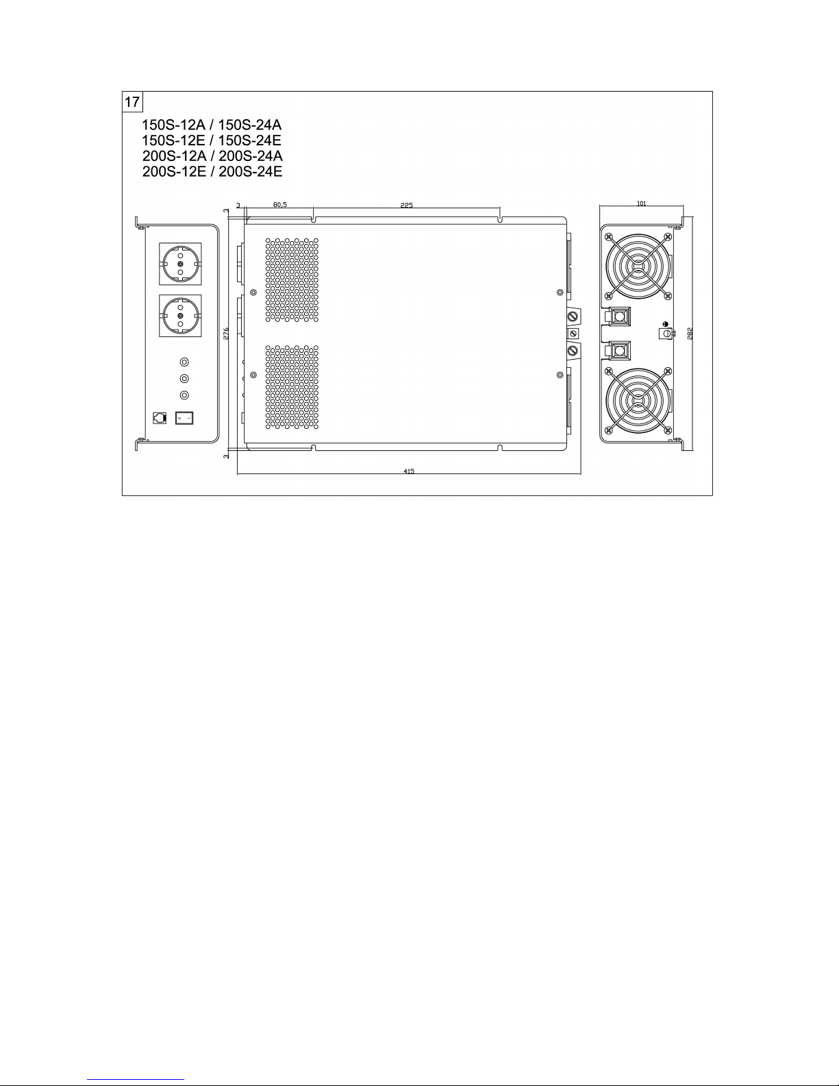
150S-12A / 150S-24A
150S-12E / 150S-24E
200S-12A / 200S-24A
200S-12E / 200S-24E
Instruction manual
Page 2
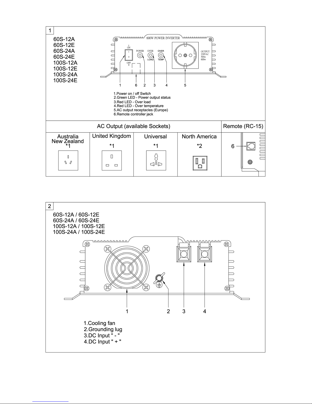
- P1 -
Page 3
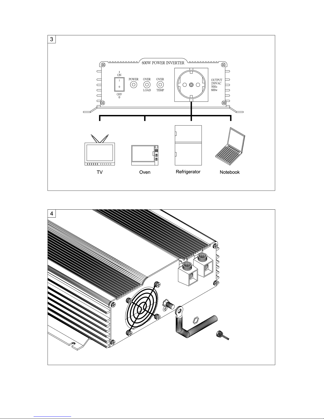
- P2 -
Page 4
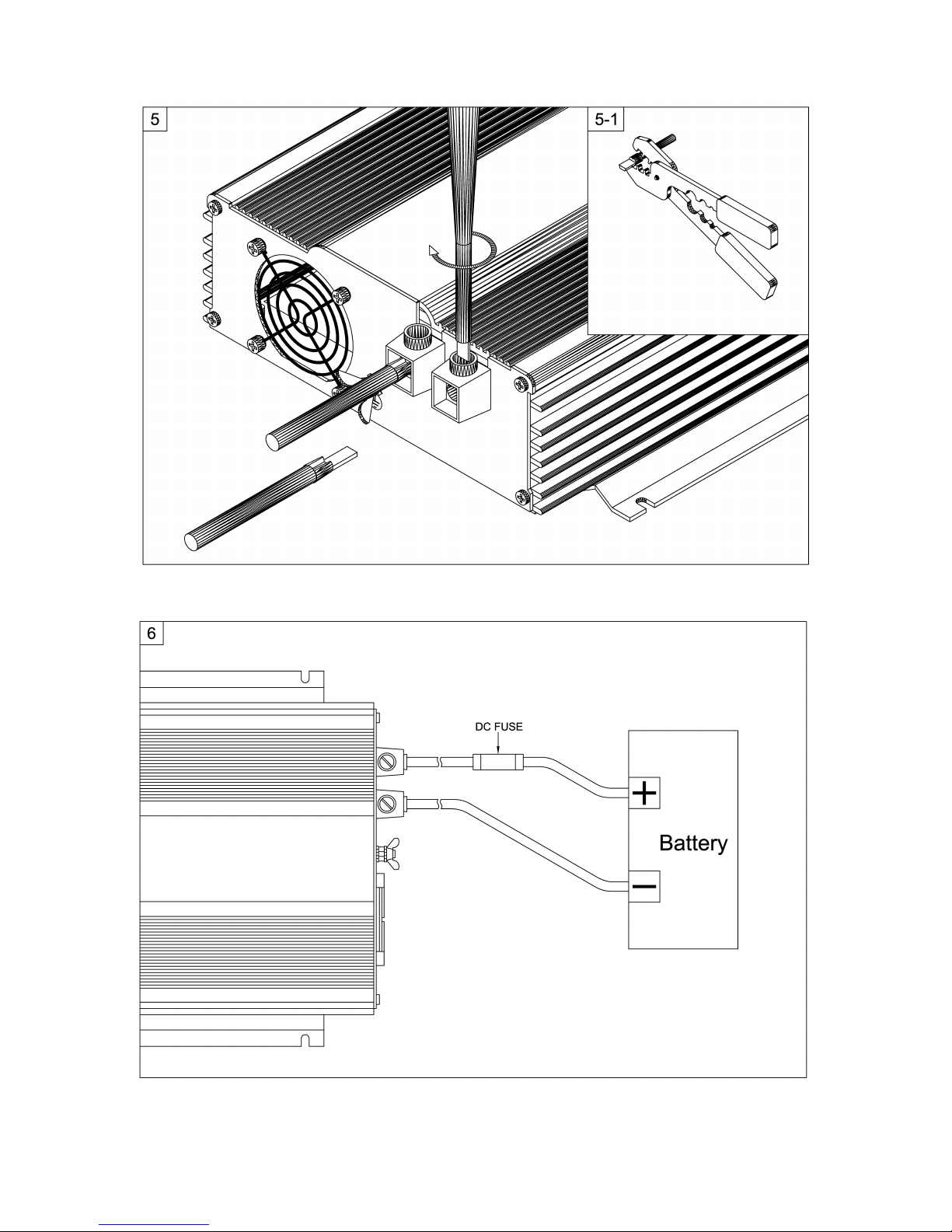
- P3 -
Page 5
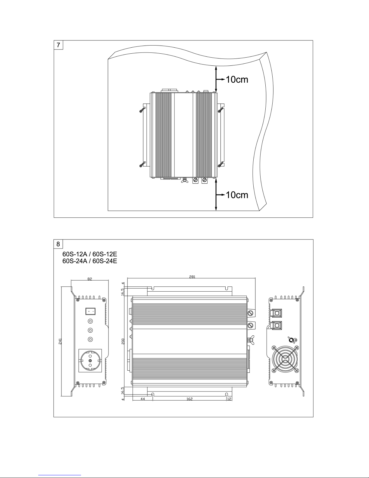
- P4 -
Page 6
- P5 -
Page 7
- P6 -
Page 8
- P7 -
Page 9
- P8 -
Page 10
- P9 -
Page 11

Sine Wave Inverter
Please read this manual carefully before installing and starting up and
store it in a safe place. If the device is resold, this instruction manual
must be handed over to the purchaser along with the device.
Contents
1 Notes on using the instruction manual. . . . . . . . . . . . . . . . . . . . . . . P11
2 General safety instructions . . . . . . . . . . . . . . . . . . . . . . . . . . . . . . .. P11
3 Scope of delivery . . . . . . . . . . . . . . . . . . . . . . . . . . . . . . . . . . . . . . . P13
4 Proper use . . . . . . . . . . . . . . . . . . . . . . . . . . . . . . . . . . . . . . . . . . . . P13
5 Technical description . . . . . . . . . . . . . . . . . . . . . . . . . . . . . . . . . . . ..P14
6 Installing the inverter . . . . . . . . . . . . . . . . . . . . . . . . . . . . . . . . . . . . P14
7 Connecting the inverter . . . . . . . . . . . . . . . . . . . . . . . . . . . . . . . . . . P16
8 Using the inverter. . . . . . . . . . . . . . . . . . . . . . . . . . . . . . . . . . . . . . . P17
9 Rectifying faults . . . . . . . . . . . . . . . . . . . . . . . . . . . . . . . . . . . . . . . ..P19
10 Cleaning and caring for the inverter. . . . . . . . . . . . . . . . . . . . . . . . . P20
11 Guarantee . . . . . . . . . . . . . . . . . . . . . . . . . . . . . . . . . . . . . . .. . .. . ..P20
12 Disposal . . . . . . . . . . . . . . . . . . . . . . . . . . . . . . . . . . . . . . . . . . . . . .P20
13 Technical data . . . . . . . . . . . . . . . . . . . . . . . . . . . . . . . .. . . . . . …. .P21
- P10 -
Page 12
Notes on using the instruction manual Sine Wave Inverter
1 Notes on using the instruction manual
Caution!
Safety instruction, failure to observe this instruction can cause
material damage and impair the function of the device.
Supplementary information for operating the device.
Caution!
Safety instruction relating to a danger from electrical current or
voltage. Failure to observe this instruction can cause material
damage and personal injury and impair the function of the device.
Note
Supplementary information for operating the device.
Action: this symbol indicates that you need to do something.
The required action is described step-by-step.
This symbol indicates the result of an action.
Please observe the following safety instructions.
2 General safety instructions
2.1 General safety
Caution!
We will not be held liable for claims for damage resulting from the
following:
– Faulty assembly or connection.
– Damage to the device resulting from mechanical influences or
overvoltage.
– Alterations to the device without the explicit permission from us.
– Usage for purposes other than those described in the installa-
tion manual.
- P11 -
Page 13

Sine Wave Inverter General safety instructions
Use the device only as intended.
Do not operate the device in a damp or wet environment.
Do not operate the device in areas that are potentially explosive.
Maintenance and repair work must only be carried out by qualified per sonnel who are familiar with the risks involved and the relevant regula tions.
2.2 Safety when installing the device
Ensure that the device has a firm foundation.
The device must be set up and fastened in such a way that it cannot tip
over or fall down.
Take the precautions necessary to ensure that children cannot interfere
with operation.
Dangerous situations may occur which cannot be recognized by
children!
Do not expose the device to a heat source (such as direct sunlight or
heating). Avoid additional heating to the device.
For installation on boats
If electrical devices are incorrectly installed on boats, corrosion damage
might occur. Have the inverter installed by a specialist (marine) electri-
cian.
Electrical cables
If cables have to be fed through metal walls or other walls with sharp
edges, use ducts or wire bushings to prevent damage.
Do not lay cables which are loose or bent next to electrically conductive
material (metal).
Do not pull on the cables.
Do not lay the 115V/230 V mains cable and the 12/24 V DC cable in the
same duct.
Fasten the cables well.
Lay the cables so that they cannot be tripped over or damaged.
- P12 -
Page 14
Scope of delivery Sine Wave Inverter
Caution!
Note the following basic safety information when using electrical
devices:
– Electric shock
– Fire hazard
– Injury
Operate the device only if you are certain that the housing and the cables
are undamaged.
Make sure the air inlets and outlets of the device are not covered.
Ensure good ventilation.
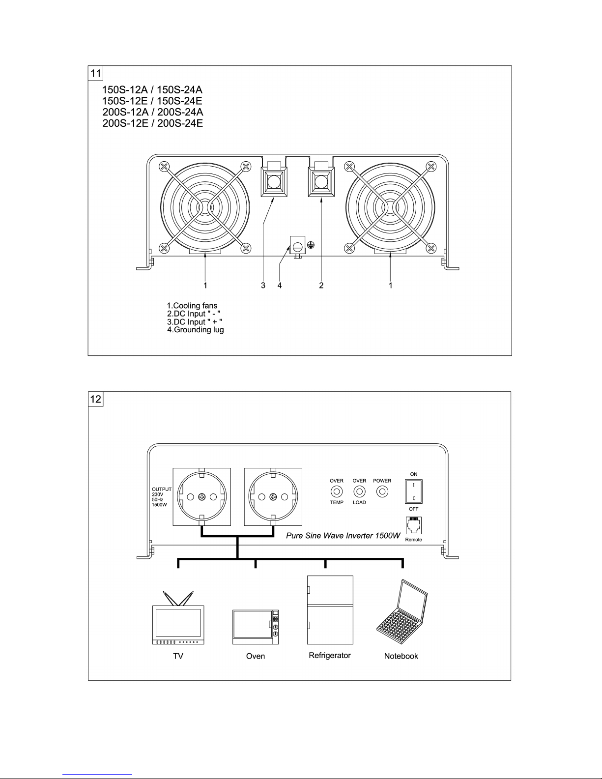
Do not connect the 115V/230 V output of the inverter (fig. 3, page 2 / fig.
12, page 6) to an appliance not using the source of 115V/230 V.
Even after the fuse triggers, parts of the inverter remain live.
Always disconnect the power supply when working on the device.
3 Scope of delivery
Quantity Description
1 Sine wave inverter
1 Operating Instructions
4 Proper use
The Pure Sine Wave Inverters convert 12 V (60S-12A/E, 100S-12A/E, 150S12A/E, 200S-12A/E) or 24 V (60S-24A/E, 100S-24A/E, 150S-24A/E, 200S24A/E) direct current to a 115V or 230V alternating current at a frequency of
50 Hz or 60Hz.
Warning!
Reverse polarity connection of the battery wires can
damage the inverter.
- P13 -
Page 15
Sine Wave Inverter Technical description
5 Technical description
The inverters can be operated wherever there is a 12 V DC supply (60S12A/E, 100S-12A/E, 150S-12A/E, 200S-12A/E) or a 24 V DC supply (60S24A/E, 100S-24A/E, 150S-24A/E, 200S-24A/E). With its low weight and the
compact design, the inverter can be easily installed into Camping mobiles,
commercial vehicles or motor and sailing yachts.
The output voltage corresponds to the socket standard (pure sinus-voltage)
Please observe the values for constant output power and peak output power
(for a max. of 10 min.) as indicated in section „Technical data“ on page 21.
Never connect an appliance that has a higher power requirement.
Note
Note the electrical driving appliances (such as power drills or
refrigerators) often need more power than is stated on the type
plate.
6 Installing the inverter
6.1 Tools required
For installation and assembly you require the following tools:
Pencil
Drill bit set
Drill
Screwdriver
- P14 -
Page 16
Installing the inverter Sine Wave Inverter
For making and testing the electrical connection the following tools are
required:
Crimping tool
3 different flexible cable connections. The required cable diameter can
be taken from the table in the section „Connecting the inverter“ on page
16.
Various terminals, multicore cable ends
For fixing the inverter you need the following mounting devices:
Screws (M4) with spacers and self-locking nuts or sheet metal screws
resp. wood screws.
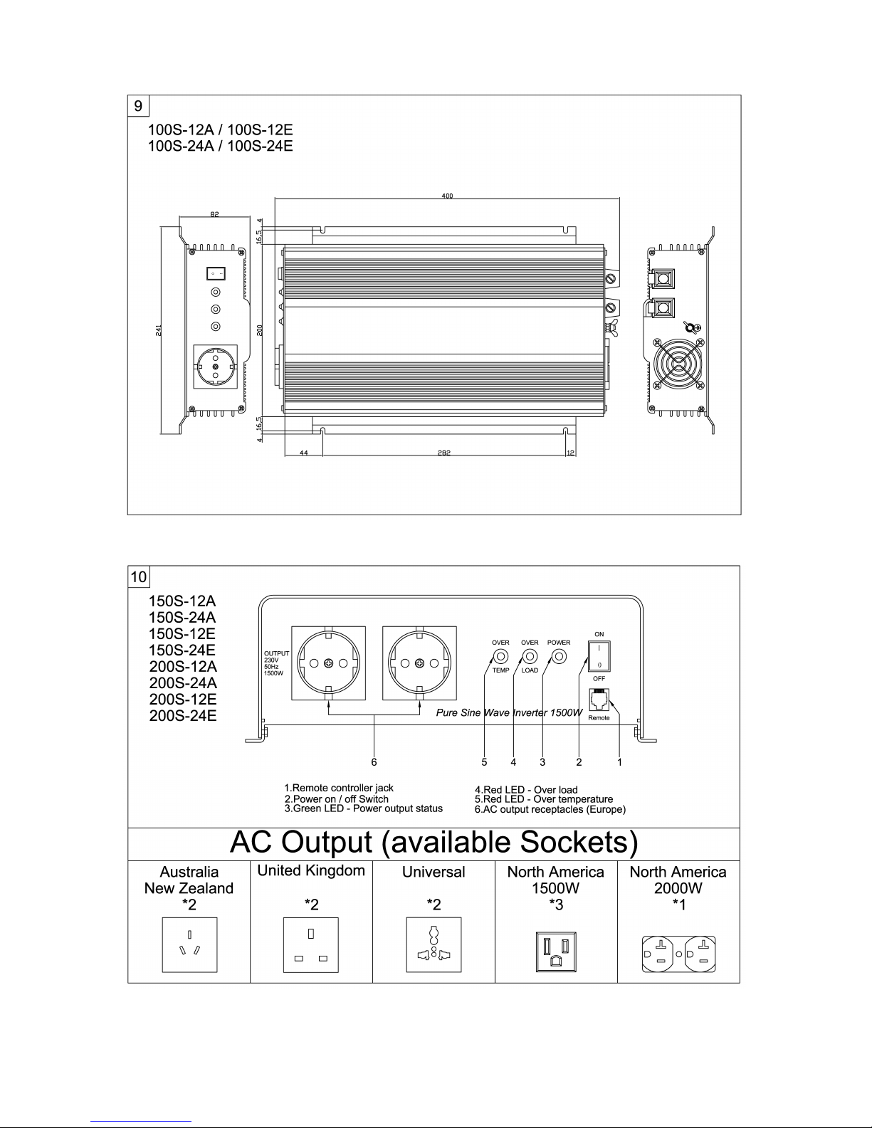
Mounting size (fig. 8, page 4/fig. 9, page 5/fig 17, page9)
6.2 Installation instructions
When selecting the installation location, observe the following instructions:
Installing the inverter can be set horizontal or vertical.
The Inverter has to be installed in a dry and clean place not exposed
to humidity.
Make sure that the place is well ventilated. If installed inside a housing,
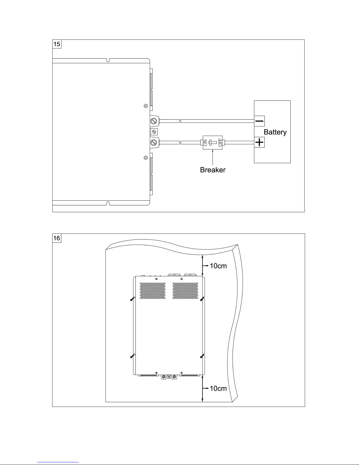
ensure proper ventilation. At least, keep a free space of 10 cm around
the inverter. (fig. 7, page 4 / fig. 16, page 8).
The air intake and the air outlet of the inverter should not be blocked.
The installation surface must be level and of sufficient strength.
Caution!
Before making any drill holes, ensure that no electrical cables or
other parts of the vehicle can be damaged by drilling, sawing and
filing.
- P15 -
Page 17
Sine Wave lnverter Connecting the inverter
6.3 Installing the inverter
Adjust the inverter to the chosen installation place and mark the fixing
points.
Fix the inverter by using the self-chosen fixing method.
7 Connecting the inverter
7.1 General instructions
In case the inverter is installed into vehicles or boats it has to be con-
nected to the chassis (ground).
On building up an electricity supply network the safety regulations
according to the VDE 0100 standard are to be kept.
Observe the required cable cross section (see table).
7.2 Connecting the inverter
Lay the flexible connecting cable (plus and minus) from the battery to
the connecting poles of the inverter (fig. 6, page 3 / fig. 15, page 8).
Warning!
Make sure that the the connection is not polarity reversed. Reverse
polarity connection will blow the internal fuses. It requres the expert
to change the fuses.
Bind the cable and the terminal firm and well together.
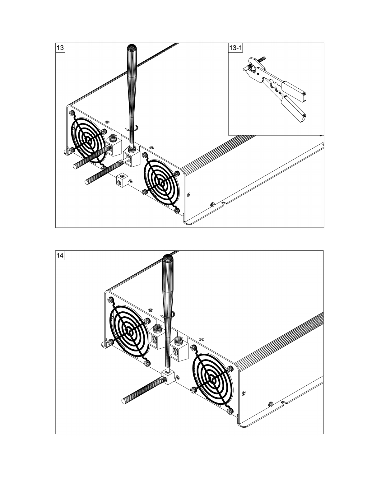
(fig. 5-1, page 3/fig13-1, page 7)
Fisrt connect the negative cable to the white negative terminal.
(fig. 6, page 3 / fig. 15, page 8)
Install a DC fuse or a breaker in the positive side of the circuit within 18
- P16 -
Device Required cable cross section
60S-12A/E 25 – 50 mm²
60S-24A/E
100S-12A/E 35 – 50 mm²
100S-24A/E
150S-12A/E 50 – 70 mm²
150S-24A/E
200S-12A/E 50 – 85 mm²
200S-24A/E
Page 18
Using the inverter Sine Wave lnverter
inches of the battery. Connect the positive cable to the red positive
terminal.
Warning!
In order for the integrated residual current-operated protective
device of the 60S-12A/E, 60S-24A/E, 100S-12A/E, 100S-24A/E,
150S-12A/E, 150S-24A/E, 200S-12A/E and 200S-24A/E inverters
to work properly, the earth connection of the inverter (fig. 4, page
2 / fig. 14, page 7) must be electrically connected to the chassis of
the vehicle or boat.
Lay the flexible earth cable from the earthing point of the vehicle to the
earthing point of the inverter.
Connect the earth cable to the chassis terminal (fig. 4, page 2 / fig. 14,
page 7).
Warning!
Reverse polarity connection of the battery wires can damage the
inverter.
8 Using the inverter
60S-12A/E, 60S-24A/E, 100S-12A/E, 100S-24A/E:
Always connect only one consumer unit to the 115V or 230 V socket (fig.
1.5, page 1)on the front of the device.
150S-12A/E, 150S-24A/E, 200S-12A/E, 200S-24A/E:
Always connect max two consumer unit to each of the 115V or 230 V
sockets (fig. 10.6, page 5) on the front of the device.
Switching on
Switching on the inverter via the ON/OFF-switch (fig. 1.1, page 1 / fig. 10.2,
page 5). When switching on, the ”Power” LED (fig. 1.2, page 1 / fig. 10.3,
page 5) illuminates.
Malfunctions
When the battery voltage falls below 10.7 V (60S-12A/E, 100S-12A/E, 150S12A/E, 200S-12A/E) resp. 21.4 V (60S-24A/E, 100S-24A/E,
- P17 -
Page 19

Sine Wave lnverter Using the inverter
150S-24A/E, 200S-24A/E), the OVER-LOAD“ LED (fig. 1.3, page 1 / fig.
10.4, page 5) illuminates and an audible signal is given. The inverter shuts
down automatically in case of a battery voltage down to 10 V resp. 20 V.
If the device overheats, the inverter shuts down – the “OVER TEMP” LED
(fig. 1.4, page 1 / fig. 10.5, page 5) lights up.
If this happens, switch off the inverter via the switch.
Ensure that the inverter is sufficiently ventilated
Wait for approx. 5 - 10 minutes and switch on the inverter manually.
When operating the inverter at high load for lengthy periods, you have to pay
attention to voltage of battery. If voltage is not enough, please charge the
battery immediately or replace battery.
There is a modular jack for remote control (fig. 1.6, page 1 / fig. 10.1, page
5) for 1500W and 2000W on the front panel and for 600W (option) and
1000W on the bottom plate.
GFCI for 60S-12A/E, 60S-24A/E, 100S-12A/E, 100S-24A/E is an option
GFCI for 150S-12A/E, 150S-24A/E, 200S-12A/E, 200S-24A/E is a must
An un-intentional electric path between a source of current and a grounded
surface is referred to as a “ground fault”. Ground faults occur when current
is leaking somewhere. In effect, electricity is escaping to the ground. How it
leaks is very important. If your body provides a path to the ground for this
leakage you could be injured, burned, severely shocked or electrocuted. A
GFCI protects people from electric shock by detecting leakage and cutting
off the AC source.
In case there is a leakage of >5mA for 115VAC ver. or >30mA for 230VAC
ver. due to ground fault, the output will be shut down. The green LED will be
switched off and the red overload LED will be lighted. The inverter gets
latched in this condition. To reset, the power on/off switch is required to be
switched off and on again. Before switching on the inverter again, ensure
that the cause of the ground fault is removed.
P18 -
Page 20

Rectifying faults Sine Wave lnverter
9 Rectifying faults
- P19 -
Fault Cause Remedy
No output voltage, LED not
Illuminated
Bad connection between
battery and inverter.
Internal fuses defect.
Check the cables and contact
In this case send the unit
back to supplier.
No output voltage, OVER-
TEMP LED illuminates
The inverter has been over-
heated.
Switch off the inverter and the
power consuming units.
Wait for approx. 5 - 10 min-
Utes and switch on the
inverter only.
Reduce the loading and
ensure a better ventilation for the
inverter.
Then switch back on the
consuming unit.
Overload LED illuminates Current consumption of the
consuming unit is too high.
Possibly, there is a short cir-
cuit in the consuming unit.
Switch off the inverter and
disconnect the consuming
units.
Switch back on the inverter
only. If the OVERLOAD LED
is off, there is a short circuit at
the consuming unit or the
total load was higher than the
performance specified within
the technical data table.
Check the connecting cable
of the consuming unit for
mechanical damages.
Acoustic signal in case of
loading
Battery voltage too low. In
case of loading battery voltage
falls below 10.7 V resp.
21.4 V.
The battery must be recharged.
Page 21

Sine Wave lnverter Cleaning and caring for the inverter
10 Cleaning and caring for the inverter
Caution!
Do not use sharp or hard objects for cleaning as these may
damage the device.
Occasionally clean the device with a damp cloth.
11 Guarantee
Our general guarantee conditions apply. If the product is defective, please
send it back to us. For repair and guarantee processing, the following
documents must be sent along with the device:
A copy of the receipt with purchasing date
A reason for complaint or description of the fault
12 Disposal
12.1 Disposing of packaging material
Do not simply throw the packaging material away. Please observe the
following instructions:
The cardboard packaging material should be disposed of in a waste-
paper bin.
Ask your local authority for the location of the recycling centre closest to
you.
- P20 -
Page 22
Technical data Sine Wave lnverter
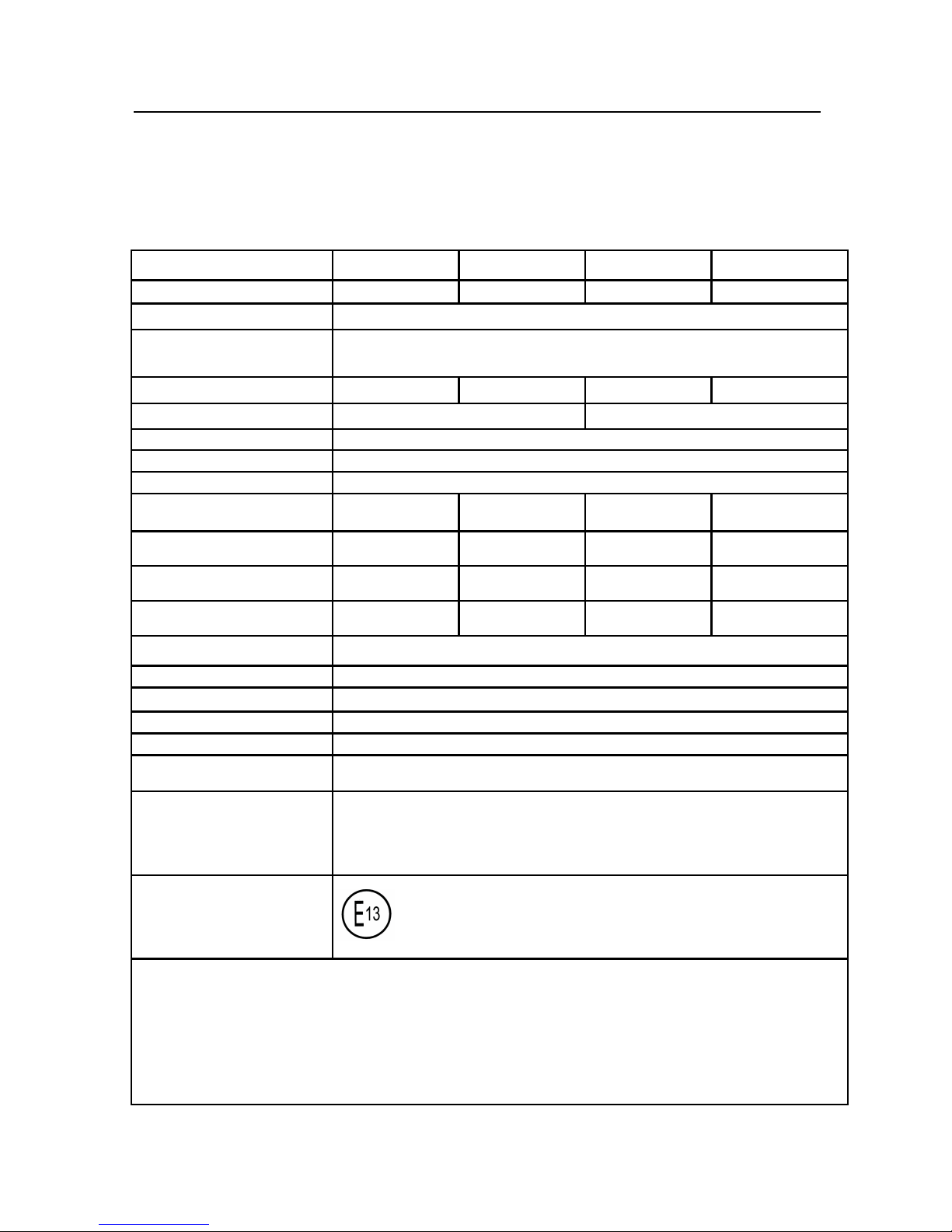
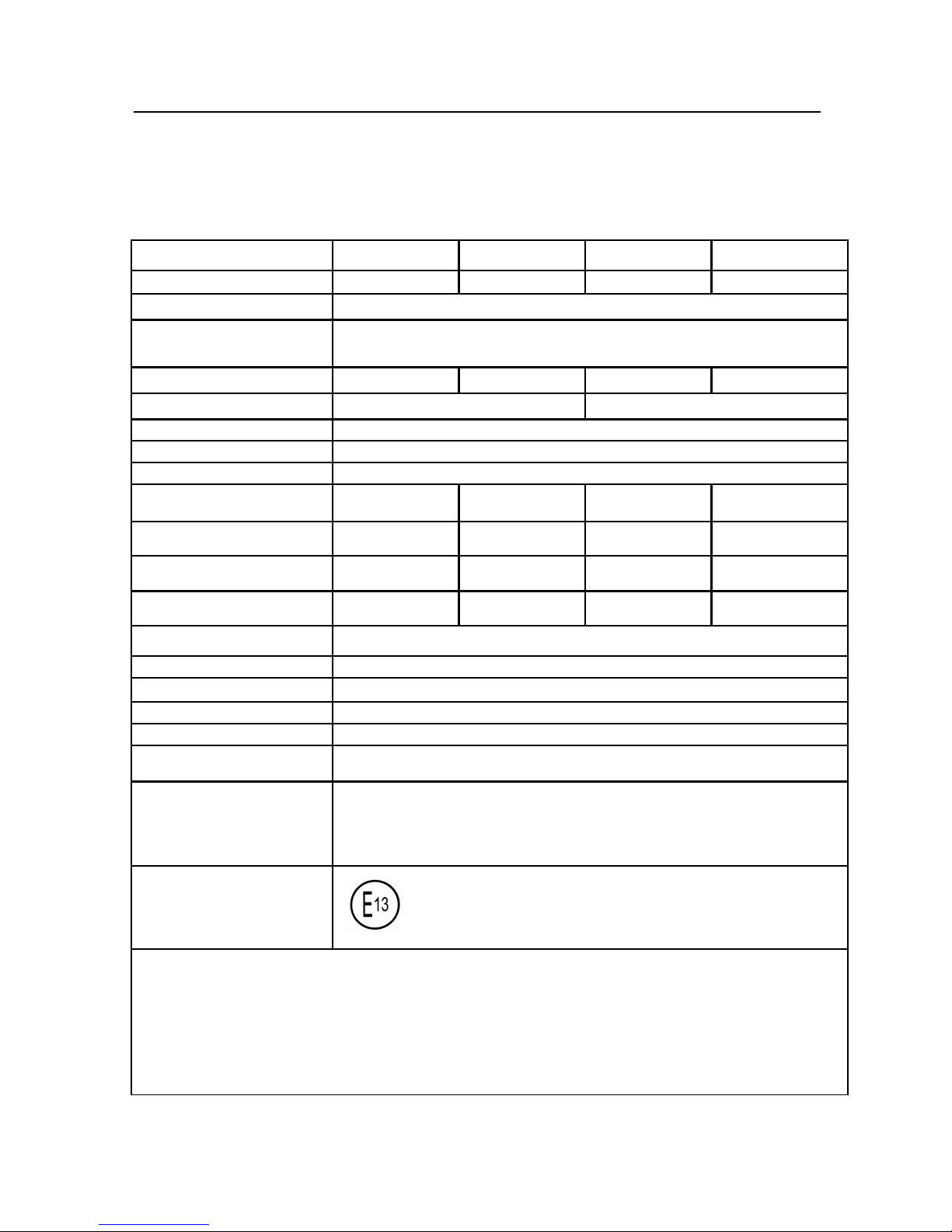
13 Technical data
600W Pure Sine Wave Inverter
- P21 -
Item number 60S-12E 60S-24E 60S-12A 60S-24A
Rated input voltage 12 V DC 24 V DC 12 V DC 24 V DC
Constant output power 600 W
Peak output power
(a max. of 10 min.)
1000 W
(650 W)
Maximum input current 80A 40A 80A 40A
Output voltage 230VAC +/- 3% 115VAC +/- 3%
Output frequency 50 Hz or 60Hz to be specified
Output Wave Form Pure Sine Wave
Total Harmonic Distortion 3%
No Load Current
<0.8A <0.6A <0.6A <0.45A
Input voltage range
10.7 V – 16.5 V 21.4 V – 33 V 10.7 V – 16.5 V 21.4 V – 33 V
Low voltage alarm
10.7 V 21.4 V 10.7 V 21.4V
Low voltage shutdown
10 V 20 V 10 V 20 V
Efficiency up to 85 %
Dimension ( LxWxH )
280 x 236 x 83 mm
Weight 2.46kgs
Remote controller RC-15(Option)
GFCI Option
Safety Certification EN60950-1 :
EMC
EN55022 : Class B
EN55024 :
EN61000-3-2 :
EN61000-3-3 :
E Mark
10R-02 3659
Protection : Reset mode
* Input low voltage………..Automatic
* Input over voltage……….Automatic
* Low battery alarm…....….Automatic
* Over temperature..…...….Automatic
* Over load………..…...…..Manual
* Short circuit ..…...…..Manual
Page 23
Sine Wave lnverter Technical data
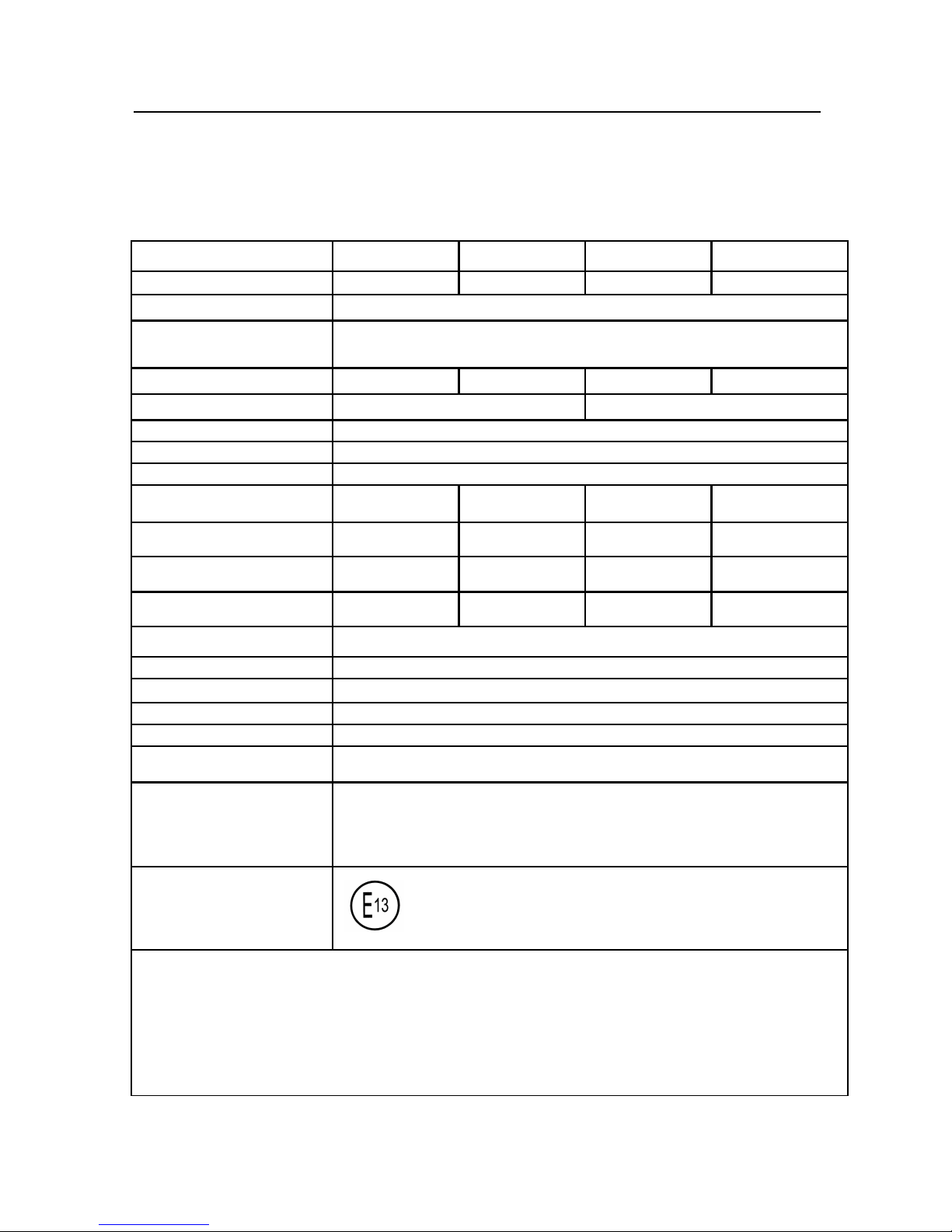
13 Technical data
1000W Pure Sine Wave Inverter
- P22-
Item number 100S-12E 100S-24E 100S-12A 100S-24A
Rated input voltage 12 V DC 24 V DC 12 V DC 24 V DC
Constant output power 1000 W
Peak output power
(a max. of 10 min.)
2000 W
(1200 W)
Maximum input current 160A 80A 160A 80A
Output voltage 230VAC +/- 3% 115VAC +/- 3%
Output frequency 50 Hz or 60Hz to be specified
Output Wave Form Pure Sine Wave
Total Harmonic Distortion 3%
No Load Current
<1.2A <0.8A <0.8A <0.6A
Input voltage range
10.7 V – 16.5 V 21.4 V – 33 V 10.7 V – 16.5 V 21.4 V – 33 V
Low voltage alarm
10.7 V 21.4 V 10.7 V 21.4V
Low voltage shutdown
10 V 20 V 10 V 20 V
Efficiency up to 85 %
Dimension ( LxWxH ) 395 x 236 x 83 mm
Weight 4kgs
Remote controller RC-15(Option)
GFCI Option
Safety Certification EN60950-1 :
EMC
EN55022 : Class B
EN55024 :
EN61000-3-2 :
EN61000-3-3 :
E Mark
10R-02 9726
Protection : Reset mode
* Input low voltage………..Automatic
* Input over voltage……….Automatic
* Low battery alarm…....….Automatic
* Over temperature..…...….Automatic
* Over load………..…...…..Manual
* Short circuit ..…...…..Manual
Page 24
Technical data Sine Wave lnverter
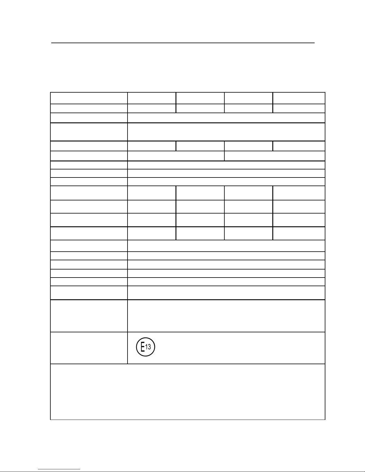
13 Technical data
1500W Pure Sine Wave Inverter
- P23-
Item number 150S-12E 150S-24E 150S-12A 150S-24A
Rated input voltage 12 V DC 24 V DC 12 V DC 24 V DC
Constant output power 1500 W
Peak output power
(a max. of 10 min.)
3000 W
(1800 W)
Maximum input current 200A 100A 200A 100A
Output voltage 230VAC +/- 3% 115VAC +/- 3%
Output frequency 50 Hz or 60Hz to be specified
Output Wave Form Pure Sine Wave
Total Harmonic Distortion 3%
No Load Current
<1.6A <1A <1A <0.6A
Input voltage range
10.7 V – 16.5 V 21.4 V – 33 V 10.7 V – 16.5 V 21.4 V – 33 V
Low voltage alarm
10.7 V 21.4 V 10.7 V 21.4V
Low voltage shutdown
10 V 20 V 10 V 20 V
Efficiency up to 85 %
Dimension ( LxWxH ) 415 x 283 x 100 mm
Weight 5.75kgs
Remote controller RC-15(Option)
GFCI Yes,please refer to page 18.
Safety Certification EN60950-1 :
EMC
EN55022 : Class B
EN55024 :
EN61000-3-2 :
EN61000-3-3 :
E Mark
10R-02 9727
Protection : Reset mode
* Input low voltage………..Automatic
* Input over voltage……….Automatic
* Low battery alarm…....….Automatic
* Over temperature..…...….Automatic
* Over load………..…...…..Manual
* Short circuit ..…...…..Manual
Page 25
Sine Wave lnverter Technical data
13 Technical data
2000W Pure Sine Wave Inverter
- P24-
Item number 200S-12E 200S-24E 200S-12A 200S-24A
Rated input voltage 12 V DC 24 V DC 12 V DC 24 V DC
Constant output power 2000 W
Peak output power
(a max. of 10 min.)
4000 W
(2200 W)
Maximum input current 240A 120A 240A 120A
Output voltage 230VAC +/- 3% 115VAC +/- 3%
Output frequency 50 Hz or 60Hz to be specified
Output Wave Form Pure Sine Wave
Total Harmonic Distortion 3%
No Load Current
<1.6A <1A <1A <0.8A
Input voltage range
10.7 V – 16.5 V 21.4 V – 33 V 10.7 V – 16.5 V 21.4 V – 33 V
Low voltage alarm
10.7 V 21.4 V 10.7 V 21.4V
Low voltage shutdown
10 V 20 V 10 V 20 V
Efficiency up to 85 %
Dimension ( LxWxH ) 415 x 283 x 100 mm
Weight 5.9kgs
Remote controller RC-15(Option)
GFCI Yes,please refer to page 18.
Safety Certification EN60950-1 :
EMC
EN55022 : Class B
EN55024 :
EN61000-3-2 :
EN61000-3-3 :
E Mark
10R-02 9594
Protection : Reset mode
* Input low voltage………..Automatic
* Input over voltage……….Automatic
* Low battery alarm…....….Automatic
* Over temperature..…...….Automatic
* Over load………..…...…..Manual
* Short circuit ..…...…..Manual
Page 26

902SI200000005
 Loading...